WO2020159106A1 - Dispositif tactile - Google Patents
Dispositif tactile Download PDFInfo
- Publication number
- WO2020159106A1 WO2020159106A1 PCT/KR2020/000557 KR2020000557W WO2020159106A1 WO 2020159106 A1 WO2020159106 A1 WO 2020159106A1 KR 2020000557 W KR2020000557 W KR 2020000557W WO 2020159106 A1 WO2020159106 A1 WO 2020159106A1
- Authority
- WO
- WIPO (PCT)
- Prior art keywords
- touch
- signal
- touch electrodes
- period
- driving
- Prior art date
- Legal status (The legal status is an assumption and is not a legal conclusion. Google has not performed a legal analysis and makes no representation as to the accuracy of the status listed.)
- Ceased
Links
Images




Classifications
-
- G—PHYSICS
- G06—COMPUTING OR CALCULATING; COUNTING
- G06F—ELECTRIC DIGITAL DATA PROCESSING
- G06F3/00—Input arrangements for transferring data to be processed into a form capable of being handled by the computer; Output arrangements for transferring data from processing unit to output unit, e.g. interface arrangements
- G06F3/01—Input arrangements or combined input and output arrangements for interaction between user and computer
- G06F3/03—Arrangements for converting the position or the displacement of a member into a coded form
- G06F3/041—Digitisers, e.g. for touch screens or touch pads, characterised by the transducing means
- G06F3/0416—Control or interface arrangements specially adapted for digitisers
- G06F3/0418—Control or interface arrangements specially adapted for digitisers for error correction or compensation, e.g. based on parallax, calibration or alignment
-
- G—PHYSICS
- G06—COMPUTING OR CALCULATING; COUNTING
- G06F—ELECTRIC DIGITAL DATA PROCESSING
- G06F3/00—Input arrangements for transferring data to be processed into a form capable of being handled by the computer; Output arrangements for transferring data from processing unit to output unit, e.g. interface arrangements
- G06F3/01—Input arrangements or combined input and output arrangements for interaction between user and computer
- G06F3/03—Arrangements for converting the position or the displacement of a member into a coded form
- G06F3/041—Digitisers, e.g. for touch screens or touch pads, characterised by the transducing means
- G06F3/044—Digitisers, e.g. for touch screens or touch pads, characterised by the transducing means by capacitive means
- G06F3/0446—Digitisers, e.g. for touch screens or touch pads, characterised by the transducing means by capacitive means using a grid-like structure of electrodes in at least two directions, e.g. using row and column electrodes
-
- G—PHYSICS
- G06—COMPUTING OR CALCULATING; COUNTING
- G06F—ELECTRIC DIGITAL DATA PROCESSING
- G06F3/00—Input arrangements for transferring data to be processed into a form capable of being handled by the computer; Output arrangements for transferring data from processing unit to output unit, e.g. interface arrangements
- G06F3/01—Input arrangements or combined input and output arrangements for interaction between user and computer
- G06F3/03—Arrangements for converting the position or the displacement of a member into a coded form
- G06F3/041—Digitisers, e.g. for touch screens or touch pads, characterised by the transducing means
- G06F3/0416—Control or interface arrangements specially adapted for digitisers
- G06F3/04162—Control or interface arrangements specially adapted for digitisers for exchanging data with external devices, e.g. smart pens, via the digitiser sensing hardware
-
- G—PHYSICS
- G06—COMPUTING OR CALCULATING; COUNTING
- G06F—ELECTRIC DIGITAL DATA PROCESSING
- G06F3/00—Input arrangements for transferring data to be processed into a form capable of being handled by the computer; Output arrangements for transferring data from processing unit to output unit, e.g. interface arrangements
- G06F3/01—Input arrangements or combined input and output arrangements for interaction between user and computer
- G06F3/03—Arrangements for converting the position or the displacement of a member into a coded form
- G06F3/041—Digitisers, e.g. for touch screens or touch pads, characterised by the transducing means
- G06F3/0416—Control or interface arrangements specially adapted for digitisers
- G06F3/04166—Details of scanning methods, e.g. sampling time, grouping of sub areas or time sharing with display driving
-
- G—PHYSICS
- G06—COMPUTING OR CALCULATING; COUNTING
- G06F—ELECTRIC DIGITAL DATA PROCESSING
- G06F3/00—Input arrangements for transferring data to be processed into a form capable of being handled by the computer; Output arrangements for transferring data from processing unit to output unit, e.g. interface arrangements
- G06F3/01—Input arrangements or combined input and output arrangements for interaction between user and computer
- G06F3/03—Arrangements for converting the position or the displacement of a member into a coded form
- G06F3/041—Digitisers, e.g. for touch screens or touch pads, characterised by the transducing means
- G06F3/044—Digitisers, e.g. for touch screens or touch pads, characterised by the transducing means by capacitive means
- G06F3/0442—Digitisers, e.g. for touch screens or touch pads, characterised by the transducing means by capacitive means using active external devices, e.g. active pens, for transmitting changes in electrical potential to be received by the digitiser
-
- G—PHYSICS
- G06—COMPUTING OR CALCULATING; COUNTING
- G06F—ELECTRIC DIGITAL DATA PROCESSING
- G06F3/00—Input arrangements for transferring data to be processed into a form capable of being handled by the computer; Output arrangements for transferring data from processing unit to output unit, e.g. interface arrangements
- G06F3/01—Input arrangements or combined input and output arrangements for interaction between user and computer
- G06F3/03—Arrangements for converting the position or the displacement of a member into a coded form
- G06F3/041—Digitisers, e.g. for touch screens or touch pads, characterised by the transducing means
- G06F3/044—Digitisers, e.g. for touch screens or touch pads, characterised by the transducing means by capacitive means
- G06F3/0445—Digitisers, e.g. for touch screens or touch pads, characterised by the transducing means by capacitive means using two or more layers of sensing electrodes, e.g. using two layers of electrodes separated by a dielectric layer
-
- H—ELECTRICITY
- H03—ELECTRONIC CIRCUITRY
- H03K—PULSE TECHNIQUE
- H03K17/00—Electronic switching or gating, i.e. not by contact-making and –breaking
- H03K17/94—Electronic switching or gating, i.e. not by contact-making and –breaking characterised by the way in which the control signals are generated
- H03K17/96—Touch switches
- H03K17/962—Capacitive touch switches
-
- G—PHYSICS
- G06—COMPUTING OR CALCULATING; COUNTING
- G06F—ELECTRIC DIGITAL DATA PROCESSING
- G06F2203/00—Indexing scheme relating to G06F3/00 - G06F3/048
- G06F2203/041—Indexing scheme relating to G06F3/041 - G06F3/045
- G06F2203/04104—Multi-touch detection in digitiser, i.e. details about the simultaneous detection of a plurality of touching locations, e.g. multiple fingers or pen and finger
-
- G—PHYSICS
- G06—COMPUTING OR CALCULATING; COUNTING
- G06F—ELECTRIC DIGITAL DATA PROCESSING
- G06F2203/00—Indexing scheme relating to G06F3/00 - G06F3/048
- G06F2203/041—Indexing scheme relating to G06F3/041 - G06F3/045
- G06F2203/04106—Multi-sensing digitiser, i.e. digitiser using at least two different sensing technologies simultaneously or alternatively, e.g. for detecting pen and finger, for saving power or for improving position detection
Definitions
- the present disclosure relates to a touch device.
- Various terminals such as mobile phones, smart phones, tablet PCs, laptop computers, digital broadcasting terminals, PDAs (Personal Digital Assistants), PMPs (Portable Multimedia Players), and navigation devices are equipped with touch sensors. do.
- the touch sensor may be located on a display panel displaying an image or may be located in an area of the terminal body. As the user interacts with the terminal by touching the touch sensor, the terminal can provide the user with an intuitive user interface.
- the stylus pen can transmit and receive signals through a touch sensor through an electrical and/or magnetic method.
- amplifiers corresponding to each of the touch electrodes are provided in the touch sensor.
- Embodiments are to provide a touch device for receiving a detection signal from which the noise component is removed.
- Embodiments are to provide a touch device for calculating the position of a touch input between two adjacent touch electrodes.
- Embodiments are to provide a touch device that detects inputs by different touch objects by varying sections within one frame.
- a touch device includes a plurality of first touch electrodes arranged in a first direction and a plurality of second touch electrodes arranged in a second direction crossing the first direction.
- the first driving signal is applied to the plurality of first touch electrodes during the first period
- the second driving is applied to the plurality of first touch electrodes and the plurality of second touch electrodes during the subsequent second period in the first period.
- a driving unit for applying a signal a receiving unit receiving a detection signal from a second touch electrode during the first period, and receiving a detection signal from a plurality of first touch electrodes and a plurality of second touch electrodes during a third period after the second period And, it includes a control unit for determining the touch position based on the signal output from the receiver.
- the driving unit may sequentially apply a pulse signal having a first frequency to the plurality of first touch electrodes as the first driving signal during the first period.
- the receiving unit may include an amplifying unit that is connected to each of the plurality of second touch electrodes during the first period and amplifies and outputs a detection signal from the corresponding second touch electrode.
- the driving unit may apply a pulse signal having a second frequency equal to or greater than a first frequency as a second driving signal to both the plurality of first touch electrodes and the plurality of second touch electrodes during the second period.
- the receiving unit may receive a detection signal from both the plurality of first touch electrodes and the plurality of second touch electrodes during the third period.
- the driving unit does not apply a second driving signal to the plurality of first touch electrodes and the plurality of second touch electrodes during the third period.
- the receiving unit may include a plurality of differential amplifying units that simultaneously receive sensing signals from both the plurality of first touch electrodes and the plurality of second touch electrodes during the third period.
- the plurality of differential amplification units may receive only the third detection signal generated by the second touch object in response to the second driving signal during the third period.
- the controller may determine the third detection signal as an effective touch signal based on whether the signal strength of the third detection signal exceeds the second threshold.
- the plurality of differential amplification units are spaced apart by a first differential amplification unit that receives sensing signals from two first touch electrodes spaced apart by at least one first touch electrode, and at least one second touch electrode.
- a second differential amplification unit may receive sensing signals from two second touch electrodes.
- the sensing signal may include at least one of a first sensing signal by the first touch object and a second sensing signal by the second touch object.
- the control unit determines the detection signal as an effective touch signal based on whether the signal strength of the detection signal received corresponding to the first driving signal during the first period exceeds the first threshold, and the first detection signal is determined as the effective touch signal
- the first threshold may be set so that the second detection signal is filtered.
- the first touch object includes at least one of a finger and a palm
- the second touch object may be a stylus pen
- a touch device includes a plurality of first touch electrodes arranged in a first direction and a plurality of second touch electrodes arranged in a second direction intersecting the first direction, and a plurality of touch panels during a first section.
- a driving unit that applies a first driving signal to the first touch electrode and applies a second driving signal to the plurality of first touch electrodes and the plurality of second touch electrodes during the subsequent second period in the first section, and the second section.
- a plurality of differential amplification units receiving detection signals from a plurality of first touch electrodes and a plurality of second touch electrodes, and a control unit determining a touch position based on signals output from the plurality of differential amplification units It includes.
- the plurality of differential amplification units may simultaneously receive the sensing signals from both the plurality of first touch electrodes and the plurality of second touch electrodes.
- the driving unit does not apply a second driving signal to the plurality of first touch electrodes and the plurality of second touch electrodes.
- the plurality of differential amplification units may receive only the third detection signal generated by the second touch object in response to the second driving signal during the third period.
- the third sensing signal may be determined as an effective touch signal based on whether the signal strength of the third sensing signal exceeds the second threshold.
- the plurality of differential amplification units are spaced apart by a first differential amplification unit that receives sensing signals from two first touch electrodes spaced apart by at least one first touch electrode, and at least one second touch electrode.
- a second differential amplification unit may receive sensing signals from two second touch electrodes.
- the sensing signal may include at least one of a first sensing signal by the first touch object and a second sensing signal by the second touch object.
- Each of the first differential amplifiers among the plurality of differential amplifiers is connected to each of the plurality of second touch electrodes during the first period to amplify and output a detection signal from the corresponding second touch electrode, and the control unit during the first period
- the sensing signal is determined as an effective touch signal based on whether the signal strength of the received sensing signal corresponding to the first driving signal exceeds a first threshold, the first sensing signal is determined as an effective touch signal, and the second sensing signal is To be filtered, a first threshold can be set.
- the first touch object includes at least one of a finger and a palm
- the second touch object may be a stylus pen
- the frequency of the first driving signal may be less than or equal to the frequency of the second driving signal.
- FIG. 1 is a schematic diagram of a touch device according to an embodiment.
- FIG. 2 is a diagram illustrating an example in which a stylus pen is touched on a touch device according to an embodiment.
- FIG. 3 is a flowchart illustrating a touch detection method according to an embodiment.
- FIG. 4 is a waveform diagram showing an example of a driving signal according to the touch detection method of FIG. 3.
- FIG. 5 is a view showing a part of a conventional touch panel and a receiver.
- FIG. 6 is a waveform diagram showing an example of a received signal received by two electrodes of the touch panel illustrated in FIG. 5.
- FIG. 7 is a diagram illustrating a part of a touch panel and a receiver according to an embodiment.
- FIG. 8 is a waveform diagram showing an example of a received signal received by two electrodes of the touch panel illustrated in FIG. 7.
- FIG. 9 to 11 are views illustrating the touch device of FIG. 1 in more detail.
- FIG. 12 is a waveform diagram showing an example of a drive signal and a reception signal according to the touch detection method of FIG. 3.
- FIG. 13 is a view showing a part of a receiving unit outputting the receiving signal of FIG. 12.
- FIG. 14 is a waveform diagram showing another example of a drive signal and a reception signal according to the touch detection method of FIG. 3.
- FIG. 15 is a view showing a part of a receiving unit outputting the receiving signal of FIG. 14.
- FIGS. 12 and 14 are graph showing the magnitude of the received signals of FIGS. 12 and 14.
- 17 and 18 are views showing touch areas of different objects.
- FIG. 19 is a block diagram illustrating a touch device and a host performing the driving method of FIG. 3.
- 20 is a diagram illustrating an example of touch data provided to a host from a touch device.
- a part such as a layer, film, region, plate, etc. is said to be “above” or “on” another part, this includes not only the case of being “just above” the other part but also another part in the middle. . Conversely, when one part is “just above” another part, it means that there is no other part in the middle. Also, being “above” or “on” the reference portion is positioned above or below the reference portion, and does not necessarily mean “above” or “on” the opposite direction of gravity. .
- FIG. 1 is a view schematically showing a touch device according to an embodiment
- FIG. 2 is a view showing an example in which a stylus pen is touched on a touch device according to an embodiment.
- the touch device 10 includes a touch panel 100 and a touch controller controlling the touch panel 100.
- the touch controller 102 may include first and second driving/receiving units 110 and 120 that transmit and receive signals to and from the touch panel 100, and a control unit 130.
- the touch panel 100 includes a plurality of first touch electrodes 111-1 to 111-m having a shape extending in a first direction and a plurality of second having a shape extending in a second direction crossing the first direction. And touch electrodes 121-1 to 121-n. Within the touch panel 100, the plurality of first touch electrodes 111-1 to 111-m may be arranged along the second direction, and the plurality of second touch electrodes 121-1 to 121-n may be It may be arranged along the first direction. In FIG. 1, the shape of the touch panel 100 is illustrated as a rectangle, but is not limited thereto.
- the touch panel 100 further includes a substrate 105 and a window 103.
- a plurality of first touch electrodes 111-1 to 111-m and a plurality of second touch electrodes 121-1 to 121-n may be positioned on the substrate 105.
- the window 103 may be positioned on the plurality of first touch electrodes 111-1 to 111-m and the plurality of second touch electrodes 121-1 to 121-n.
- the plurality of first touch electrodes 111-1 to 111-m and the plurality of second touch electrodes 121-1 to 121-n are illustrated as being located on the same layer, but are respectively located on different layers. It may, but is not limited to.
- the plurality of first touch electrodes 111-1 to 111-m are connected to the first drive/receiver 110, and the plurality of second touch electrodes 121-1 to 121-n are the second drive/receiver It is connected to 120.
- the first drive/receiver 110, the second drive/receiver 120, and the controller 130 are illustrated separately, but may be implemented as one module, unit, or chip, and are limited thereto. Does not work.
- the first driving/receiving unit 110 may apply driving signals to the plurality of first touch electrodes 111-1 to 111-m. Also, the first driving/receiving unit 110 may receive a sensing signal from the plurality of first touch electrodes 111-1 to 111-m. Similarly, the second driving/receiving unit 120 may apply driving signals to the plurality of second touch electrodes 121-1 to 121-n. Also, the second driving/receiving unit 120 may receive a sensing signal from the plurality of first touch electrodes 121-1 to 121-n. That is, the first drive/receiver 110 and the second drive/receiver 120 may be a type of transceiver that transmits and receives signals, and may each include a driver and a receiver.
- the driving signal may include a signal having a frequency corresponding to the resonant frequency of the stylus pen 20 (eg, a sine wave, a square wave, etc.).
- the resonant frequency of the stylus pen 20 depends on the design value of the resonant circuit part 23 of the stylus pen.
- the touch device 10 may be used to detect a touch input (direct touch or proximity touch) by a touch object. As illustrated in FIG. 2, a touch input of the stylus pen 20 close to the touch panel 100 may be sensed by the touch device 10.
- the stylus pen 20 may include a conductive tip 21, a resonant circuit portion 23, a ground portion 25, and a body portion 27.
- the conductive tip 21 is formed of at least a portion of a conductive material (eg, metal, conductive rubber, conductive fabric, conductive silicone, etc.), and may be electrically connected to the resonant circuit 23.
- a conductive material eg, metal, conductive rubber, conductive fabric, conductive silicone, etc.
- the resonant circuit 23 is an LC resonant circuit, and includes a plurality of first touch electrodes 111-1 to at least one of the first drive/receiver 110 and the second drive/receiver 120 through the conductive tip 21. 111-m) and a plurality of second touch electrodes 121-1 to 121-n may resonate with a driving signal applied to at least one type of electrode.
- the resonance signal generated by the resonance circuit 23 resonating with the driving signal may be output to the touch panel 100 through the conductive tip 21.
- the resonant circuit 23 is located in the body portion 27 and may be electrically connected to the ground portion 25.
- the stylus pen 20 in this manner generates a touch input by generating a resonance signal in response to a driving signal applied to at least one of the touch electrodes 111-1 to 111-m and 121-1 to 121-n.
- a driving signal applied to at least one of the touch electrodes 111-1 to 111-m and 121-1 to 121-n.
- the capacitance Cx is formed by at least one of the touch electrodes 111-1 to 111-m and 121-1 to 121-n and the conductive tip 21 of the stylus pen 20. Through the capacitance Cx between at least one of the touch electrodes 111-1 to 111-m, 121-1 to 121-n and the conductive tip 21, a driving signal is transmitted to the stylus pen 20 side , The resonance signal may be transmitted to the touch panel 100 side.
- the touch device 10 is a touch object (for example, a user's body part (finger, palm, etc.), passive, or active (active) other than the stylus pen 20 using the method of generating the resonance signal described above. ) Stylus pen) may be detected, but is not limited thereto.
- a touch object for example, a user's body part (finger, palm, etc.), passive, or active (active) other than the stylus pen 20 using the method of generating the resonance signal described above.
- Stylus pen may be detected, but is not limited thereto.
- the touch device 10 detects a touch by a stylus pen that receives an electrical signal and outputs it as a magnetic field signal.
- the touch device 10 may further include a digitizer.
- a magnetic field signal electromagnetically resonant (or electromagnetically induced) by the stylus pen is detected by the digitizer, so that a touch can be detected.
- the touch device 10 detects a touch by a stylus pen that receives a magnetic field signal and outputs it as a resonant magnetic field signal.
- the touch device 10 may further include a coil and a digitizer for applying a current as a driving signal.
- the stylus pen resonates with the magnetic field signal generated by the current-applied coil.
- the stylus pen may detect a touch by detecting an electromagnetic resonance (or electromagnetic induction) magnetic field signal by a digitizer.
- the controller 130 controls driving of the touch device 10 and may output touch coordinate information in response to a touch detection result of the touch device 10.
- FIG. 3 is a flowchart illustrating a touch detection method according to an embodiment.
- the touch device 10 is driven in the first mode (S10).
- the first mode is a mode in which a driving signal for detecting a touch input by a touch object other than the stylus pen 20 is applied to the touch panel 100.
- the first drive/receiver 110 outputs drive signals to the plurality of first touch electrodes 111-1 to 111-m
- the second drive/receiver 120 includes a plurality of The sensing signals according to the touch are received from the second touch electrodes 121-1 to 121-n.
- the controller 130 determines whether the detection signal is an effective touch signal based on whether the signal size of the detection signal obtained in the first section exceeds the first threshold, and acquires touch coordinate information using the effective touch signal. Can.
- the controller 130 calculates the touch coordinates using the detection signal. If the signal size of the detection signal obtained in the first section is less than or equal to the first threshold, the controller 130 does not calculate touch coordinates according to the detection signal whose signal size is less than or equal to the first threshold. In addition, when the signal size of the detection signal obtained in the first section exceeds the first threshold, the controller 130 may calculate the touch area using the detection signal.
- the detection signal obtained in the first section includes at least one of a first detection signal by a user's body part (finger, palm, etc.), a stylus pen 20, and a second detection signal by a passive stylus pen.
- the first threshold may be set such that the first detection signal is determined as an effective touch signal and the second detection signal is filtered.
- the touch device 10 is driven in the second mode (S12 ).
- the second mode is a mode in which a driving signal for detecting a touch input by the stylus pen 20 is applied to the touch panel 100.
- the first driving/receiving unit 110 simultaneously applies driving signals to all of the plurality of first touch electrodes 111-1 to 111-m.
- the first drive/receiver 110 simultaneously applies driving signals to all of the plurality of first touch electrodes 111-1 to 111-m, but the second in the second section.
- the driving/receiving unit 120 simultaneously applies driving signals to all of the plurality of second touch electrodes 121-1 to 121-n, or the first driving/receiving unit 110 and the second driving/receiving unit 120 are applied.
- driving signals may be applied to all of the plurality of first touch electrodes 111-1 to 111-m, and driving signals may be applied to all of the plurality of second touch electrodes 121-1 to 121-n.
- the first drive/receiver 110 and the second drive/receiver 120 are both a plurality of first touch electrodes 111-1 to 111-m and a plurality of second touch electrodes 121-1 to 121-n.
- a driving signal is applied to the driving signals applied to the plurality of first touch electrodes 111-1 to 111-m and the driving signals applied to the plurality of second touch electrodes 121-1 to 121-n It is assumed that the phases are the same, but is not limited thereto.
- the frequency of the driving signal applied to the touch panel 100 in the first period is equal to or less than the frequency of the driving signal applied to the touch panel 100 in the first sub-section.
- the touch device 10 receives the sensed signal resonated based on the driving signal (S14 ).
- the resonant circuit portion 23 of the stylus pen 20 resonates with the driving signal, whereby a resonant signal is generated and transmitted to the touch panel 100 through the conductive tip 21.
- the first drive/receiver 110 receives a sensing signal transmitted from the plurality of first touch electrodes 111-1 to 111-m
- the second drive/receiver 120 receives a plurality of second touches
- the sensing signals transmitted from the electrodes 121-1 to 121-n are received.
- the first drive/receiver 110 and the second drive/receiver 120 may process the received detection signal and transmit it to the controller 130.
- the control unit 130 determines whether the detection signal is based on whether the signal size of the detection signal acquired in the second sub-section exceeds the second threshold, and the touch of the stylus pen 20 using the effective touch signal It is possible to obtain touch coordinate information of the generated point.
- the controller 130 calculates the touch coordinates using the detection signal. If the signal size of the detection signal obtained in the third section is less than or equal to the second threshold, the controller 130 does not calculate touch coordinates according to the detection signal whose signal size is less than or equal to the second threshold. In addition, when the signal size of the detection signal obtained in the third section exceeds the second threshold, the control unit 130 may calculate the touch area using the detection signal.
- FIG. 4 is a waveform diagram showing an example of a driving signal according to the touch detection method of FIG. 3.
- the first driving/receiving unit 110 may include at least one of the plurality of first touch electrodes 111-1 to 111-m and the plurality of second touch electrodes 121-1 to 121-n.
- the driving signal is output to one type of touch electrodes.
- the second driving/receiving unit 120 includes a plurality of second touch electrodes 121-1. To 121-n).
- the controller 130 may acquire touch coordinate information based on the signal size of the detection signal.
- the first driving/reception section 110 simultaneously applies driving signals to the plurality of first touch electrodes 111-1 to 111-m
- the second The driving/receiving unit 120 simultaneously applies driving signals to the plurality of second touch electrodes 121-1 to 121-n.
- frequencies of driving signals applied to the plurality of first touch electrodes 111-1 to 111-m and the plurality of second touch electrodes 121-1 to 121-n are stylus pens.
- the frequency of the driving signal output to the plurality of first touch electrodes 111-1 to 111-m and the plurality of second touch electrodes 121-1 to 121-n during the first sub-interval T21. May be a frequency within an offset of 25 kHz around 500 kHz.
- the frequencies of the driving signals output to the plurality of first touch electrodes 111-1 to 111-m are set differently from the resonance frequency of the stylus pen 20.
- the frequency of the driving signals output to the plurality of first touch electrodes 111-1 to 111-m during the first period T1 may be set to about 150 kHz.
- the frequency setting of the driving signal is only an example, and may be set to a different value from the above.
- the first driving/receiving section 110 receives the sensing signals from the plurality of first touch electrodes 111-1 to 111-m, and the second driving /The receiving unit 120 receives a detection signal from the plurality of second touch electrodes 121-1 to 121-n.
- the resonance signals output by the resonance circuit 23 of the stylus pen 20 may include a plurality of first touch electrodes 111-1 to 111-m and It may be received by at least one of the plurality of second touch electrodes 121-1 to 121-n.
- the second section T2 includes a plurality of first sub sections T21 and second sub sections T22.
- first sub sections T21 and second sub sections T22 may be repeated 8 times.
- the second section T2 is described after the first section T1, the first section T1 may exist after the second section T2, and the first section T1 and the second section T1 may exist.
- the time length of the two sections T2 may be changed within several frames, and the driving method of the touch device 10 in the embodiment is not limited thereto.
- FIG. 5 is a view showing a part of a conventional touch panel and a driving unit
- FIG. 6 is a waveform diagram showing an example of a received signal received by two electrodes of the touch panel shown in FIG. 5
- FIG. 7 is a diagram according to an embodiment
- FIG. 8 is a waveform diagram showing an example of a received signal received by two electrodes of the touch panel illustrated in FIG. 7.
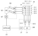
- the first receiving unit 1100 of the first driving/receiving unit 110 includes a plurality of differential amplifier units (or differential amplifier units) 113-1 and 113-2, and an ADC unit 115. ), and signal processing units (DSP, 117 ).
- the second receiving unit 1200 of the second driving/receiving unit 120 includes a plurality of differential amplifying units 123-1 and 123-2, an ADC unit 125, and signal processing units DSP and 127.
- the differential amplification units 113-1 and 113-2, 123-1 and 123-2 input a sensing signal from one touch electrode to one input terminal of the two input terminals, and another touch adjacent to the other input terminal. It may be implemented as an amplifier (amplifier) to which the sensing signal from the electrode is input.
- noise In general, not only a desired signal but also noise is received in the signal received from the touch electrode. This noise degrades the quality of the signal and degrades the sensitivity of the system. In the case of display noise generated from a display, noise is introduced into a similar size in all channels. Therefore, when amplifying the difference between the sensed signals received by the two touch electrodes, the noise components cancel each other out, and only the difference between the signals is amplified to obtain a good quality signal.
- the input terminals of the differential amplification units 113-1 and 113-2, 123-1 and 123-2 are respectively connected to two adjacent touch electrodes.
- the differential amplification unit 113-1 is connected to the first touch electrodes 111-1 and 111-2 adjacent to each other, and the differential amplification unit 113-2 is the first touch electrodes adjacent to each other ( 111-3, 111-4).
- the differential amplifier 123-1 is connected to the second touch electrodes 121-1 and 121-2 adjacent to each other, and the differential amplifier 123-2 is adjacent to the second touch electrodes 121- to each other. 3, 121-4).
- Each of the differential amplification units 113-1 and 113-2, 123-1 and 123-2 may differentially amplify and output two sensing signals transmitted from the touch electrodes connected to the input terminal.
- a differential amplifier connected to the two touch electrodes 111-1 and 111-2 (113-1) amplifies the difference between the two detection signals.
- the controller 130 determines whether the detection signals from the two touch electrodes 111-1 and 111-2 are effective touch signals using the signal output by the differential amplifier 113-1.
- the sensing signals received from the two touch electrodes 111-1 and 111-2 have the same size and phase, or are very similar, the signal output by the differential amplifier 113-1 is very small.
- the sensing signals R_111-1 and R-111-2 from the two touch electrodes 111-1 and 111-2 are similar to each other. It can have magnitude and phase. Therefore, the signal O_113-1 output by the differential amplification unit 113-1 has a very small signal size ⁇ Va. Therefore, there is a problem that it is difficult to detect a touch input to a point TP.
- the differential amplification unit 113-1 receives a detection signal from two adjacent touch electrodes, a detection signal by a touch in a region between the first touch electrode 111-1 and the first touch electrode 111-2 Even if it is differentially amplified by the differential amplification unit 113-1, the value is not large enough. Therefore, when the differential amplifier 113-1 is connected to two adjacent touch electrodes, the touch sensitivity is deteriorated.
- each of the differential amplification units 113-1 and 113-2, 123-1 and 123-2 are respectively connected to two touch electrodes spaced from each other by at least one touch electrode. It is connected.
- the differential amplifier 113-1 is connected to the first touch electrodes 111-1 and 111-3 spaced apart by the first touch electrode 111-2, and the differential amplifier 113 -2) is connected to the first touch electrodes 111-2 and 111-4 separated by the first touch electrode 111-3.
- the differential amplification unit 123-1 is connected to the second touch electrodes 121-1 and 121-3 spaced apart by the second touch electrode 121-2, and the differential amplification unit 123-2 ) Is connected to the second touch electrodes 121-2 and 121-4 separated by the second touch electrode 121-2.
- a differential amplifier connected to the two touch electrodes 111-1 and 111-3 (113-1) amplifies the difference between the two detection signals.
- the controller 130 determines whether the detection signals from the two touch electrodes 111-1 and 111-3 are effective touch signals using the signal output by the differential amplifier 113-1. However, since the signal sizes between the sensed signals received from the two touch electrodes 111-1 and 111-3 are different, the signal output by the differential amplifier 113-1 may have a magnitude greater than a threshold. .
- the detection signals R_111-1 and R-111-2 from the two touch electrodes 111-1 and 111-2 are different from each other. Can have a size Therefore, the signal O_113-1 output by the differential amplification unit 113-1 has a signal magnitude ⁇ Vb equal to or greater than a threshold. That is, since the differential amplification unit 113-1 receives detection signals from the first touch electrode 111-1 and the first touch electrode 111-3 spaced apart from each other by at least one touch electrode, touch is performed.
- the detection signal by the touch electrode at the input position may be differentially amplified to have a sufficiently large value, and touch sensitivity may be improved.
- FIG. 9 is a view more specifically showing a touch device operating in the first section T1.
- FIG. 9 is a view showing a touch device in a first section.
- the first driving unit 1110 of the first driving/receiving unit 110 includes a plurality of amplifiers 112-1 to 112-m.
- the plurality of amplifiers 112-1 to 112-m are connected to the plurality of first touch electrodes 111-1 to 111-m to output a first driving signal.
- the second receiving unit 1200 includes a plurality of amplifying units 123-1 to 123-n, an ADC unit 125, and a signal processing unit (DSP, 127).
- the second driving/receiving unit 1200 may sequentially receive the detection signals of the plurality of second touch electrodes 121-1 to 121-n in one second touch electrode unit. Alternatively, the second driving/receiving unit 1200 may simultaneously receive the sensing signals through the plurality of second touch electrodes 121-1 to 121-n.
- Each of the plurality of amplification units 123-1 to 123-n is connected to a corresponding second touch electrode among the plurality of second touch electrodes 121-1 to 121-n.
- each of the plurality of amplification units 123-1 to 123-n may be implemented as an amplifier in which one of the two input terminals is connected to ground or a DC voltage, and a sensing signal is input to the other input terminal.
- Each of the plurality of amplifying units 123-1 to 123-n amplifies and outputs a sensing signal transmitted from the plurality of second touch electrodes 121-1 to 121-n in parallel.
- the ADC unit 125 converts the amplified detection signal into a digital signal. Then, the signal processing unit 127 processes a plurality of amplified signals converted into digital signals and transmits them to the control unit 130.
- a plurality of amplifiers 112-1 to 112-m of the first driver 1110 are connected to the plurality of first touch electrodes 111-1 to 111-m to drive the second drive. Output a signal.
- the second driving unit 1210 also includes a plurality of amplifying units 122-1 to 122-n.
- the plurality of amplification units 122-1 to 122-n are connected to the plurality of first touch electrodes 121-1 to 121-n to output a third driving signal.
- FIG. 11 is a diagram illustrating a touch device operating in the second sub-section T22 of the second section T2.
- the first receiving unit 1100 includes a plurality of differential amplifying units (or differential amplifying units) 113-1 to 113-i, an ADC unit 115, and a signal processing unit (DSP, 117).
- the second receiving unit 1200 includes a plurality of differential amplifying units 123-1 to 123-j, an ADC unit 125, and a signal processing unit (DSP, 127).
- the plurality of differential amplifiers 113-1 to 113-i and 123-1 to 123-j may be configured by changing the connection of input terminals of the plurality of amplifiers 123-1 to 123-n. That is, i+j ⁇ n.
- the ground of the two input terminals of the amplification unit 123-1 or the input terminal connected to the DC voltage is connected to the corresponding second touch electrode 121-4, and the ground of the two input terminals of the amplification unit 123-1 is By connecting the input terminal to which the DC voltage is connected to the corresponding second touch electrode 121-5, two touch electrodes may be connected to one amplification unit.
- each of the differential amplifiers 113-1 to 113-i and 123-1 to 123-j are respectively connected to two touch electrodes spaced apart from each other by at least one touch electrode.
- Each of the differential amplifying units 113-1 to 113-i and 123-1 to 123-j may differentially amplify and output two sensing signals transmitted from the touch electrodes.
- Each of the differential amplification units 113-1 to 113-i and 123-1 to 123-j receives a sensing signal from two touch electrodes and differentially amplifies them, so even if a driving signal is simultaneously applied to a plurality of touch electrodes, saturation Does not work.
- Each of the differential amplification units 113-1 to 113-i and 123-1 to 123-j may receive a sensing signal from two adjacent touch electrodes, not two adjacent touch electrodes.
- each of the differential amplifiers 113-1 to 113-i and 123-1 to 123-j receives a sensing signal from two touch electrodes spaced apart from one or more touch electrodes.
- the differential amplification unit 113-1 receives a sensing signal from the touch electrode 111-1 and the touch electrode 111-5.
- the differential amplification unit 113-1 receives a detection signal from two adjacent touch electrodes (for example, the first touch electrode 111-1 and the first touch electrode 111-2), the first touch electrode
- the sensing signals due to the touch in the region between (111-1) and the first touch electrode 111-2 are not sufficiently large even though they are differentially amplified by the differential amplifier 113-1. Therefore, when the differential amplifier 113-1 is connected to two adjacent touch electrodes, the touch sensitivity is deteriorated.
- the differential amplification unit 113-1 since the differential amplification unit 113-1 receives a detection signal from the first touch electrode 111-1 and the first touch electrode 111-5, the detection signal by the touch electrode at the location where the touch is input is generated. It can be differentially amplified to have a sufficiently large value, and touch sensitivity can be improved.
- Each of the ADC units 115 and 125 converts the differentially amplified sensing signal into a digital signal.
- each of the signal processing units 117 and 127 processes a plurality of differential amplified signals converted into digital signals and transmits them to the control unit 130.
- the touch detection method will be described with reference to FIGS. 12 to 16.
- FIG. 12 is a waveform diagram showing an example of a driving signal and a reception signal according to the touch detection method of FIG. 3, and
- FIG. 13 is a diagram showing a part of a receiving unit outputting the reception signal of FIG. 11.
- a finger touch is applied to an area where the first touch electrodes 111-1, 111-2 and the second touch electrodes 121-1, 121-2, 121-3 intersect. It is assumed to exist.
- first driving signals D_111-1 to D_111-m are sequentially applied to the plurality of first touch electrodes 111-1 to 111-m.
- the first driving signals D_111-1 to D_111-m are pulse signals having an enable level voltage VE and a disable level voltage VD.
- the second receiver 1200 receives the detection signals R_121-1 to R_121-n from the plurality of second touch electrodes 121-1 to 121-n.
- the first driving signals D_111-1 to D_111-m are driving signals for detecting a touch input by a touch object other than the stylus pen 20, and are not limited to the waveform shown in FIG. 12.
- the first driving signals D_111-1 to D_111-m are sequentially applied to the plurality of first touch electrodes 111-1 to 111-m, but the plurality of first touch electrodes 111- Driving signals having different frequencies (for example, frequencies having an orthogonal relationship with each other) may be simultaneously applied to 1 to 111-m.
- the second receiver 1200 receives the sensing signal according to the touch from the plurality of second touch electrodes 121-1 to 121-n, and uses the band pass filters of different frequency bands to detect the sensing signals first. It can be separated for each touch electrode (111-1 to 111-m).
- the detection signal R_121-1 from the second touch electrode 121-1 is amplified and output through the corresponding amplifying unit 123-1, and the second touch electrode 121-
- the detection signal R_121-2 from 2) is amplified and output through the corresponding amplification unit 123-1, and the detection signal R_121-3 from the second touch electrode 121-3 corresponds to the amplification.
- Amplified through the unit 123-1 is output, and the detection signal R_121-4 from the second touch electrode 121-4 can be amplified and output through the corresponding amplification unit 123-1.
- a change in signal size due to a touch occurs as ⁇ V0, ⁇ V1, and ⁇ V2, respectively.
- the controller 130 includes first touch electrodes 111-1 and 111-2 to which a driving signal is applied when a signal size change occurs and second touch electrodes 121-1 and 121-2 where a signal size change occurs. , 121-3) can intersect with the touch coordinates.
- the second driving signals D_111-1 to D_111-m are applied to all of the plurality of first touch electrodes 111-1 to 111-m, and the plurality of second The third driving signal D_121 is applied to all of the touch electrodes 121-1 to 121-n.
- the second and third driving signals D_111 and D_121 are pulse signals having an enable level voltage VE and a disable level voltage VD, and a frequency similar to the resonant frequency of the stylus pen 20. .
- reception of detection signals from the plurality of first touch electrodes 111-1 to 111-m and the plurality of second touch electrodes 121-1 to 121-n is not performed. .
- the first receiver 1100 and the second receiver 1200 may include a plurality of first touch electrodes 111-1 to 111-m and a plurality of second touch electrodes 121-1 to 121-n) It is possible to receive a detection signal from all.
- the second section T2 includes a plurality of first sub sections T21 and a second sub section T22.
- the combination of the first sub section T21 and the second sub section T22 may be repeated 8 times.
- FIG. 14 is a waveform diagram showing another example of a driving signal and a reception signal according to the touch detection method of FIG. 3, and FIG. 15 is a diagram showing a part of a driving unit outputting the reception signal of FIG. 14.
- first driving signals D_111-1 to D_111-m are sequentially applied to the plurality of first touch electrodes 111-1 to 111-m.
- the second receiver 1200 receives the detection signals R_121-1 to R_121-n from the plurality of second touch electrodes 121-1 to 121-n.
- the signal size change value ⁇ V3 of the detection signal R_121-5 from the second touch electrode 121-5 with a touch is amplified. It can be amplified through the unit 123-5 and output.
- the second driving signals D_111-1 to D_111-m are applied to all of the plurality of first touch electrodes 111-1 to 111-m.
- the third driving signal D_121 is applied to all of the plurality of second touch electrodes 121-1 to 121-n.
- the second and third driving signals D_111 and D_121 are pulse signals having an enable level voltage VE and a disable level voltage VD, and a frequency similar to the resonant frequency of the stylus pen 20. .
- the enable level voltage VE and the disable level voltage VD of the second and third drive signals D_111 and D_121 are identical to each other, but are in-phase signals. It is not limited to this.
- the magnitude of the pen resonance signal increases according to the time at which the second and third driving signals D_111 and D_121 are applied. And, after a certain period of time, the magnitude of the pen resonance signal is saturated.
- reception of detection signals from the plurality of first touch electrodes 111-1 to 111-m and the plurality of second touch electrodes 121-1 to 121-n is not performed. .
- the first driving unit 1110 stops applying the driving signal D_111
- the second driving unit 1210 also stops applying the driving signal D_121.
- a driving signal (a) is applied to the plurality of first touch electrodes 111-1 to 111-m and the plurality of second touch electrodes 121-1 to 121-n. D_111, D_121) are not applied.
- the first receiver 1100 and the second receiver 1200 may include a plurality of first touch electrodes 111-1 to 111-m and a plurality of second touch electrodes 121-1 to 121-n) It is possible to receive a detection signal from all.
- the first receiver 1100 and the second receiver 1200 may receive the pen resonance signal in the second sub-section T22 to which the driving signals D_111 and D_121 are not applied as a sensing signal.
- the signal size difference ⁇ V4 may be amplified and output through the differential amplifier 113-2.
- the signal size difference between the detection signal R_121-5 from the second touch electrode 121-5 with touch and the detection signal R_121-1 from the second touch electrode 121-1 without touch ( ⁇ V5) may be amplified and output through the differential amplifier 123-1.
- the controller 130 includes first touch electrodes 111-1 and 111-2 to which a driving signal is applied when a signal size difference is generated, and second touch electrodes 121-2 and 121-3 where a signal size difference is generated. ) Can be calculated as the touch point.
- the control unit 130 may calculate the touch position in the touch panel 100 through the detection signal received in the second sub-section T22.
- the differential amplification unit 113-1 is spaced apart from each other by at least one touch electrode, the first touch electrode 111-1 and the first touch electrode 111- Since the sensing signal is received from 3), the sensing signal by the touch electrode at the touch input position can be differentially amplified to have a sufficiently large value, and the touch sensitivity can be improved.
- the touch device 10 may include a plurality of first touch electrodes 111-1 to 111-m and a plurality of second touch electrodes 121-1 to 121- in the second sub-section T22. n) Since the detection signals are received through all of them, there is an advantage in that touch coordinates along two axes intersecting each other can be quickly acquired.
- the touch device 10 may include a plurality of first touch electrodes 111-1 to 111-m and a plurality of second touch electrodes 121-1 to 121-n in the first section T1. ) Simultaneously applying the same driving signals D_111 and D_121 to all of them, there is an advantage in that the resonance signal size of the stylus pen 20 responding thereto is improved.
- the detection signal reception may be performed at least once in the second sub-section T22 by at least one of the first receiving unit 1100 and the second receiving unit 1200.
- the time point for receiving the detection signal may be at least one time point in the second sub-interval T22, but is not limited thereto.
- One frame 1 FRAME includes a first section T1 and a first sub-section T21.
- the first sub-interval T21 includes a first sub-interval T21 and a second sub-interval T22.
- the second sub-section T22 ends, the first section of the next frame is started.
- the magnitude difference of the detection signal by the finger is ⁇ V1, ⁇ V2, which exceeds the first threshold Threshold1.
- the difference in the magnitude of the detection signal by the stylus pen 20 is ⁇ V3, which is equal to or less than the first threshold Threshold1.
- the controller 130 determines a detection signal having a size difference exceeding a first threshold Th1 in the first period T1 as an effective touch signal.
- the first threshold (Threshold1) is such that the first detection signal by the user's body part (finger, palm, etc.) is determined as an effective touch signal and the second detection signal by the stylus pen 20 and the passive stylus pen is filtered. Can be set.
- the controller 130 determines the detection signal by the finger as an effective touch signal, and calculates the touch coordinates using the detection signal.
- the controller 130 determines that the detection signal by the stylus pen 20 is not an effective touch signal, and does not calculate touch coordinates.
- the magnitude difference of the detection signal by the stylus pen 20 is ⁇ V4, ⁇ V5, which exceeds the second threshold (Threshold2).
- the control unit 130 determines a detection signal having a size difference exceeding a second threshold value in the first sub-interval T21 as an effective touch signal. Therefore, the control unit 130 determines the detection signal by the stylus pen 20 as an effective touch signal, and calculates the touch coordinates using the detection signal.
- touch coordinates are calculated using only the detection signal in the first section T1, so that the touch position by the touch object with small signal size change is accurately calculated. There was a difficult problem.
- the first threshold is the first detection signal by the user's body part (finger, palm, etc.) is determined as an effective touch signal and the stylus pen 20, the passive stylus pen 2
- the detection signal is set to be filtered. Accordingly, touch coordinates by a touch object having a large signal size change may be accurately detected in the first section T1, and touch coordinates by a touch object having a small signal size change may be accurately detected in the first sub-section T21. Can.
- 17 and 18 are views showing touch areas of different objects.
- a finger 30 touches the touch panel 100.
- a plurality of touch electrodes 111-3 to 111-5 and 121-4 to 121-6 may be positioned in the vicinity of the area A1 where the tip of the finger 30 contacts the touch panel 100.
- the area of the touch area A1 may be calculated using the detection signals received from the plurality of touch electrodes 111-3 to 111-5, 121-4 to 121-6.
- the stylus pen 40 touches the touch panel 100.
- One first touch electrode 111-6 and one second touch electrode 121-6 may be positioned near an area A2 where the tip of the stylus pen 40 contacts the touch panel 100.
- two first touch electrodes and two second touch electrodes may be positioned near the area A2 where the tip of the stylus pen 40 contacts the touch panel 100. That is, the tip of the stylus pen 40 is located in the area A2 where the tip of the stylus pen 40 contacts the touch panel 100 than the number of touch electrodes located in the area A1 where the tip of the finger 30 contacts the touch panel 100. The number of touch electrodes is smaller. Therefore, the area of the touch area A2 by the touch of the stylus pen 40 is calculated as a very small value compared to the touch area A1 by the touch of the finger 30.
- the touch device 10 may transmit touch data including information about an area of the touch area to the host device.
- the host device may identify whether the touch object is a finger 30 or a stylus pen 40.
- the touch device 10 may determine a touch object according to the calculated area of the touch area, and may transmit touch data including information on the determined touch object to the host device.
- FIG. 19 is a block diagram illustrating a touch device and a host according to an embodiment
- FIG. 20 is a diagram illustrating an example of touch data provided to a host from a touch device.
- the host 50 may receive touch data to the touch controller 102 included in the touch device 10.
- the host 50 is a mobile system-on-chip (SoC), an application processor (AP), a media processor (Media Processor), a microprocessor, a central processing unit (CPU), or It may be a similar device.
- SoC mobile system-on-chip
- AP application processor
- Media Processor media processor
- microprocessor microprocessor
- CPU central processing unit
- the touch device 10 may generate information about the touch input during one frame as touch data and transmit it to the host 50.
- the touch device 10 when the first section T1 ends, the touch device 10 generates information about the touch input during the first section T1 as touch data and transmits it to the host 50, and transmits the information on the touch to the host 50.
- the first sub-interval T21 that is continuous in is terminated, information on the touch input during the first sub-interval T21 may be generated as touch data and transmitted to the host 50.
- the touch data 60 may include a touch count field 61 and at least one touch entity field 62 and 63.
- a value indicating the number of touches input during one frame period may be written in the touch count field 61.
- the touch count field In (61) a value indicating that two touches are input is written.
- the touch entity fields 62 and 63 include fields indicating information about each touch input.
- the touch entity fields 62 and 63 are flag fields 620, X axis coordinate fields 621, Y axis coordinate fields 622, Z value fields 623, area fields 624, and touch actions.
- Field 625 is flag fields 620, X axis coordinate fields 621, Y axis coordinate fields 622, Z value fields 623, area fields 624, and touch actions.
- the number of touch entity fields 62 and 63 may be the same as the value written in the touch count field 61.
- a value indicating a touch object may be written. For example, fingers, palms, and stylus pens may be written in the flag field 620 with different values from each other.
- values representing the calculated touch coordinates may be written in the X-axis coordinate field 621 and the Y-axis coordinate field 622 .
- values representing the calculated touch coordinates may be written in the Z value field 623 .
- a value corresponding to the signal strength of the detection signal may be written.
- the area field 624 a value corresponding to the area of the touched area may be written.
- the host device 50 receiving the touch data 60 uses the value of the area field 624 to determine that the touch object is the finger 30 when the touch area is greater than the threshold value, and then touch If the area is below a threshold, it is determined that the touch object is a stylus pen 40.
- the host device 50 receiving the touch data 60 may use the value of the flag field 620 to identify whether the touch object is a finger 30 or a stylus pen 40. have.
Landscapes
- Engineering & Computer Science (AREA)
- General Engineering & Computer Science (AREA)
- Theoretical Computer Science (AREA)
- Human Computer Interaction (AREA)
- Physics & Mathematics (AREA)
- General Physics & Mathematics (AREA)
- Position Input By Displaying (AREA)
Abstract
Selon un mode de réalisation, l'invention concerne un dispositif tactile qui comprend : un panneau tactile comprenant une pluralité de premières électrodes tactiles agencées dans une première direction et une pluralité de secondes électrodes tactiles agencées dans une seconde direction croisant la première direction ; une unité d'attaque pour appliquer un premier signal d'attaque à la pluralité de premières électrodes tactiles pendant un premier intervalle ; une unité de réception pour appliquer un deuxième signal d'attaque à la pluralité de premières électrodes tactiles et à la pluralité de secondes électrodes tactiles pendant un deuxième intervalle après le premier intervalle, recevoir un signal de détection provenant des secondes électrodes tactiles pendant le premier intervalle, et recevoir un signal de détection provenant de la pluralité de premières électrodes tactiles et de la pluralité de secondes électrodes tactiles pendant un troisième intervalle après le deuxième intervalle ; et une unité de commande pour déterminer une position de contact sur la base d'un signal délivré en sortie par l'unité de réception.
Priority Applications (2)
| Application Number | Priority Date | Filing Date | Title |
|---|---|---|---|
| CN202411183057.XA CN119148885A (zh) | 2019-02-01 | 2020-01-13 | 触摸装置 |
| CN202080011987.0A CN113412464B (zh) | 2019-02-01 | 2020-01-13 | 触摸装置 |
Applications Claiming Priority (2)
| Application Number | Priority Date | Filing Date | Title |
|---|---|---|---|
| KR1020190014045A KR102224833B1 (ko) | 2019-02-01 | 2019-02-01 | 터치 장치 |
| KR10-2019-0014045 | 2019-02-01 |
Publications (1)
| Publication Number | Publication Date |
|---|---|
| WO2020159106A1 true WO2020159106A1 (fr) | 2020-08-06 |
Family
ID=71836384
Family Applications (1)
| Application Number | Title | Priority Date | Filing Date |
|---|---|---|---|
| PCT/KR2020/000557 Ceased WO2020159106A1 (fr) | 2019-02-01 | 2020-01-13 | Dispositif tactile |
Country Status (4)
| Country | Link |
|---|---|
| US (2) | US20200249791A1 (fr) |
| KR (1) | KR102224833B1 (fr) |
| CN (2) | CN113412464B (fr) |
| WO (1) | WO2020159106A1 (fr) |
Families Citing this family (7)
| Publication number | Priority date | Publication date | Assignee | Title |
|---|---|---|---|---|
| KR102764364B1 (ko) * | 2019-06-12 | 2025-02-07 | 주식회사 하이딥 | 터치 장치 및 이의 터치 검출 방법 |
| US11579726B2 (en) * | 2019-09-11 | 2023-02-14 | Beijing Boe Display Technology Co., Ltd. | Touch device, electronic device and driving method |
| KR20220008997A (ko) * | 2020-07-14 | 2022-01-24 | 삼성디스플레이 주식회사 | 전자장치 |
| KR102596709B1 (ko) * | 2021-02-04 | 2023-11-02 | 주식회사 하이딥 | 스타일러스 구동장치 및 이를 포함하는 전자장치 |
| KR102495665B1 (ko) * | 2021-12-06 | 2023-02-06 | 주식회사 지2터치 | 전력 소모를 감소시킬 수 있는 액티브 펜 위치 검출 방법 및 액티브 펜 위치 검출 장치 |
| KR102681191B1 (ko) * | 2021-12-30 | 2024-07-03 | 주식회사 지2터치 | 면적 및 전력 소모를 감소시킬 수 있는 액티브 펜 위치 검출 방법 및 액티브 펜 위치 검출 장치 |
| CN120143999A (zh) * | 2024-04-02 | 2025-06-13 | 义隆电子股份有限公司 | 触控感测系统及其控制方法 |
Citations (5)
| Publication number | Priority date | Publication date | Assignee | Title |
|---|---|---|---|---|
| US20090078476A1 (en) * | 2007-09-26 | 2009-03-26 | N-Trig Ltd. | Method for identifying changes in signal frequencies emitted by a stylus interacting with a digitizer sensor |
| KR20140022153A (ko) * | 2012-08-13 | 2014-02-24 | 엘지디스플레이 주식회사 | 터치모듈을 포함하는 표시장치 및 그 구동방법 |
| KR20140111586A (ko) * | 2013-03-11 | 2014-09-19 | 가부시키가이샤 재팬 디스프레이 | 터치 센서 장치, 표시 장치 및 전자 기기 |
| KR20160025443A (ko) * | 2014-08-27 | 2016-03-08 | 삼성전자주식회사 | 터치 패널 및 이를 구비한 좌표 측정 시스템 |
| KR20160105465A (ko) * | 2014-01-03 | 2016-09-06 | 쓰리엠 이노베이티브 프로퍼티즈 컴파니 | 차동 신호 기법을 이용하는 용량성 터치 시스템 및 방법 |
Family Cites Families (16)
| Publication number | Priority date | Publication date | Assignee | Title |
|---|---|---|---|---|
| US6144371A (en) * | 1998-03-18 | 2000-11-07 | International Business Machines Corporation | Thinkscribe combined electronic and paper based scheduling |
| US6362440B1 (en) * | 1998-03-27 | 2002-03-26 | International Business Machines Corporation | Flexibly interfaceable portable computing device |
| WO2012039837A1 (fr) * | 2010-09-22 | 2012-03-29 | Cypress Semiconductor Corporation | Stylet capacitif destiné à un écran tactile |
| JP6240530B2 (ja) * | 2014-02-21 | 2017-11-29 | 株式会社ワコム | 信号処理回路、信号処理方法、位置検出装置及び電子機器 |
| JP2015232602A (ja) * | 2014-06-09 | 2015-12-24 | 株式会社ジャパンディスプレイ | 表示装置 |
| US10379694B2 (en) * | 2014-08-27 | 2019-08-13 | Samsung Electronics Co., Ltd. | Touch panel and coordinate measuring system having the same |
| US10613643B2 (en) * | 2015-06-25 | 2020-04-07 | Apple Inc. | Method for stylus touch-down and lift-off noise mitigation |
| US10031614B2 (en) * | 2015-07-02 | 2018-07-24 | Innolux Corporation | Touch display panel and driving method thereof |
| US10198089B2 (en) * | 2015-09-08 | 2019-02-05 | Apple Inc. | Active stylus precision tip |
| CN105045437B (zh) * | 2015-09-18 | 2018-11-06 | 京东方科技集团股份有限公司 | 一种触控感测电极、触控感测方法及设备 |
| JP6479625B2 (ja) * | 2015-10-13 | 2019-03-06 | 株式会社ジャパンディスプレイ | タッチ検出機能付き表示装置 |
| US10474286B2 (en) * | 2016-10-25 | 2019-11-12 | Lg Display Co., Ltd. | Touch display device, active pen, touch system, touch circuit, and pen recognition method |
| US10585502B2 (en) * | 2017-08-17 | 2020-03-10 | Apple Inc. | Touch sensor excitation using transformer |
| KR102206051B1 (ko) * | 2019-01-22 | 2021-01-21 | 주식회사 하이딥 | 터치 장치 및 이의 터치 검출 방법 |
| KR102738420B1 (ko) * | 2019-09-20 | 2024-12-04 | 주식회사 하이딥 | 스타일러스 펜, 터치 장치, 및 터치 시스템 |
| KR20210124649A (ko) * | 2020-04-07 | 2021-10-15 | 주식회사 하이딥 | 터치 장치 및 이의 터치 검출 방법 |
-
2019
- 2019-02-01 KR KR1020190014045A patent/KR102224833B1/ko active Active
-
2020
- 2020-01-13 CN CN202080011987.0A patent/CN113412464B/zh active Active
- 2020-01-13 CN CN202411183057.XA patent/CN119148885A/zh active Pending
- 2020-01-13 WO PCT/KR2020/000557 patent/WO2020159106A1/fr not_active Ceased
- 2020-01-16 US US16/744,429 patent/US20200249791A1/en not_active Abandoned
-
2023
- 2023-07-24 US US18/225,264 patent/US12561025B2/en active Active
Patent Citations (5)
| Publication number | Priority date | Publication date | Assignee | Title |
|---|---|---|---|---|
| US20090078476A1 (en) * | 2007-09-26 | 2009-03-26 | N-Trig Ltd. | Method for identifying changes in signal frequencies emitted by a stylus interacting with a digitizer sensor |
| KR20140022153A (ko) * | 2012-08-13 | 2014-02-24 | 엘지디스플레이 주식회사 | 터치모듈을 포함하는 표시장치 및 그 구동방법 |
| KR20140111586A (ko) * | 2013-03-11 | 2014-09-19 | 가부시키가이샤 재팬 디스프레이 | 터치 센서 장치, 표시 장치 및 전자 기기 |
| KR20160105465A (ko) * | 2014-01-03 | 2016-09-06 | 쓰리엠 이노베이티브 프로퍼티즈 컴파니 | 차동 신호 기법을 이용하는 용량성 터치 시스템 및 방법 |
| KR20160025443A (ko) * | 2014-08-27 | 2016-03-08 | 삼성전자주식회사 | 터치 패널 및 이를 구비한 좌표 측정 시스템 |
Also Published As
| Publication number | Publication date |
|---|---|
| CN113412464A (zh) | 2021-09-17 |
| CN119148885A (zh) | 2024-12-17 |
| CN113412464B (zh) | 2024-09-13 |
| US20200249791A1 (en) | 2020-08-06 |
| KR20200095978A (ko) | 2020-08-11 |
| US20230367422A1 (en) | 2023-11-16 |
| KR102224833B1 (ko) | 2021-03-08 |
| US12561025B2 (en) | 2026-02-24 |
Similar Documents
| Publication | Publication Date | Title |
|---|---|---|
| WO2020153657A1 (fr) | Dispositif tactile et procédé de détection tactile associé | |
| WO2020159106A1 (fr) | Dispositif tactile | |
| WO2020209639A1 (fr) | Dispositif tactile et procédé de détection tactile associé | |
| WO2020251288A1 (fr) | Dispositif tactile et procédé de détection tactile associé | |
| WO2021054604A1 (fr) | Stylet, dispositif tactile et système tactile | |
| WO2016114614A1 (fr) | Stylet tactile, panneau tactile, et système d'indication de coordonnées les comprenant | |
| WO2015002440A1 (fr) | Procédé de changement de mode d'un numériseur | |
| WO2011142610A2 (fr) | Circuit intégrateur avec intégrateur inverseur et intégrateur non inverseur | |
| WO2015023136A1 (fr) | Procédé et appareil de reconnaissance d'état de préhension dans un dispositif électronique | |
| WO2017171224A1 (fr) | Stylet, appareil électronique pour recevoir un signal du stylet, et procédé de commande associé | |
| WO2020251212A1 (fr) | Dispositif tactile et son procédé de pilotage | |
| WO2020209534A1 (fr) | Dispositif électronique et son procédé de commande | |
| WO2019146918A1 (fr) | Procédé de reconnaissance d'empreinte digitale, et dispositif électronique et support de stockage associés | |
| WO2018230875A1 (fr) | Terminal et son procédé de commande | |
| WO2015190753A1 (fr) | Pavé à entrées multiples pour détecter simultanément un toucher capacitif et une entrée de champ électromagnétique induit, et système d'entrée | |
| WO2013051752A1 (fr) | Appareil et procédé permettant de détecter un contact | |
| WO2018076818A1 (fr) | Procédé de sauvegarde de données, appareil, dispositif électronique, support de stockage et système | |
| WO2013129742A1 (fr) | Procédé de détection de position pour panneau tactile et circuit intégré | |
| WO2020032668A1 (fr) | Procédé et dispositif permettant de traiter une entrée d'utilisateur sur la base du temps pendant lequel une entrée d'utilisateur est maintenue | |
| WO2019160348A1 (fr) | Dispositif électronique d'acquisition d'une entrée d'utilisateur en état submergé à l'aide d'un capteur de pression, et procédé de commande de dispositif électronique | |
| WO2020013453A1 (fr) | Dispositif tactile et procédé de détection de toucher associé | |
| WO2021206264A1 (fr) | Appareil tactile et procédé de détection de toucher associé | |
| WO2017183804A1 (fr) | Dispositif d'écran tactile, dispositif d'entrée et procédé de commande et procédé associés | |
| WO2021132743A1 (fr) | Dispositif électronique permettant d'afficher un contenu portant sur une application et son procédé de commande | |
| WO2023121023A1 (fr) | Dispositif d'entrée tactile |
Legal Events
| Date | Code | Title | Description |
|---|---|---|---|
| 121 | Ep: the epo has been informed by wipo that ep was designated in this application |
Ref document number: 20748855 Country of ref document: EP Kind code of ref document: A1 |
|
| NENP | Non-entry into the national phase |
Ref country code: DE |
|
| 122 | Ep: pct application non-entry in european phase |
Ref document number: 20748855 Country of ref document: EP Kind code of ref document: A1 |