WO2020161848A1 - Curseur pour une fermeture à glissière cachée - Google Patents
Curseur pour une fermeture à glissière cachée Download PDFInfo
- Publication number
- WO2020161848A1 WO2020161848A1 PCT/JP2019/004350 JP2019004350W WO2020161848A1 WO 2020161848 A1 WO2020161848 A1 WO 2020161848A1 JP 2019004350 W JP2019004350 W JP 2019004350W WO 2020161848 A1 WO2020161848 A1 WO 2020161848A1
- Authority
- WO
- WIPO (PCT)
- Prior art keywords
- pair
- pull tab
- slider
- posture
- shaft
- Prior art date
- Legal status (The legal status is an assumption and is not a legal conclusion. Google has not performed a legal analysis and makes no representation as to the accuracy of the status listed.)
- Ceased
Links
Images


Classifications
-
- A—HUMAN NECESSITIES
- A44—HABERDASHERY; JEWELLERY
- A44B—BUTTONS, PINS, BUCKLES, SLIDE FASTENERS, OR THE LIKE
- A44B19/00—Slide fasteners
- A44B19/24—Details
- A44B19/26—Sliders
- A44B19/30—Sliders with means for locking in position
- A44B19/308—Sliders with means for locking in position in the form of a spring-actuated locking member actuated by the pull member
-
- A—HUMAN NECESSITIES
- A44—HABERDASHERY; JEWELLERY
- A44B—BUTTONS, PINS, BUCKLES, SLIDE FASTENERS, OR THE LIKE
- A44B19/00—Slide fasteners
- A44B19/24—Details
- A44B19/26—Sliders
- A44B19/30—Sliders with means for locking in position
- A44B19/306—Sliders with means for locking in position in the form of a locking spring member actuated by the pull member
Definitions
- the present invention relates to a slider for a hidden slide fastener, in which the body of the slider is hidden on the back side in the thickness direction of the fabric and the pull tab of the slider appears on the front side in the thickness direction of the fabric.
- sliders for slide fasteners that have an automatic stop function.
- sliders for slide fasteners There are two types of sliders for slide fasteners that have an automatic stop function.
- the first type is commonly called an automatic slider. This is to switch contact and separation of the lock member with respect to the pair of element rows depending on whether or not the pulling operation is performed on the pull tab. Due to the switching, the movement of the body in the front-rear direction is restricted or released. More specifically, the automatic slider has two functions. The first function is that the lock member automatically comes into contact with the pair of element rows when the hand is released from the pull tab, and as a result, the front and rear positions of the slider are locked, making it difficult for the slider to move. The second function is that the lock member is separated from the pair of element rows by pulling the pull tab, and as a result, the lock is released and the slider is easily moved.
- the second type of slider for slide fasteners that has an automatic stop function is commonly called a semi-automatic slider.
- the contact and separation of the lock member with respect to the pair of element rows is switched depending on the attitude of the puller with respect to the body.
- the function of the semi-automatic slider is that the front and rear positions of the slider are locked when the puller is in the lying position with respect to the torso regardless of the pulling operation with respect to the puller, and unlocked when the puller is in the upright position with respect to the torso. ..
- Patent Document 1 discloses an automatic slider. This is a hidden slide fastener slider because it has a pair of tape grooves on the upper surface of the body. More details are as follows.
- This automatic slider has a body, a lock member that can lock the front-rear position of the body, and is fixed to the upper part of the body in the front-rear direction. And a swingable pull tab.
- the upper part of the fuselage has left and right flanges, an upper wing plate arranged between the left and right flanges, and a pair of tape grooves formed between the upper wing plate and the left and right flanges.
- the tape is passed through the pair of tape grooves.
- the tape is bent so as to face the lower surface and the upper surface of the flange, and the cloth is fixed to the portion facing the upper surface.
- the pair of cloth covers the left and right side portions of the upper surface of the body. Therefore, the automatic slider of Patent Document 1 is a slider for a hidden slide fastener.
- the body and the lock member cooperate to form a pull tab attachment portion.
- the pull tab attachment portion has a hole inside which the pull tab connection ring is inserted. The lower surface of this hole is lower than the upper surface of the flange. Further, the cloth is arranged above the flange via a tape. When the slider is moved by pulling the pull tab, the connecting ring is pulled up and floats above the upper surface of the flange, so that the pair of cloths are not damaged by the pull tab (connecting ring).
- Patent Documents 2 and 3 disclose semi-automatic sliders. This is not a hidden slide fastener slider because it has tape grooves on the left and right sides of the body. More details are as follows.
- This semi-automatic slider includes a body, a pull tab that can be rotated back and forth around a shaft, and a lock member that is fixed to the front part of the upper part of the body and that is vertically displaced by a cam portion of the shaft. is there. Further, the body is provided with a tape groove between the left and right edge portions of the upper and lower vanes facing each other in the vertical direction, that is, the left and right side surfaces. Then, a pair of tapes are passed through the tape grooves, and a pair of cloths are fixed to the pair of tapes on the left and right outside of the tape grooves. Then, the entire upper surface of the body is exposed between the pair of cloths, and the upper surface of the body is not hidden by the cloths. Therefore, the semi-automatic sliders disclosed in Patent Documents 2 and 3 are sliders for hidden slide fasteners. is not.
- the sliders disclosed in Patent Documents 2 and 3 are semi-automatic sliders, but they are not for hidden slide fasteners.
- the slider disclosed in Patent Document 1 is an automatic slider as described above, and is not a semi-automatic slider. Therefore, the present inventor has provided a function of a semi-automatic slider (a function in which the front and rear positions of the slider are locked when the puller is in the lying position with respect to the torso of the puller regardless of the pulling operation with respect to the puller, and unlocked when the puller is in the standing position with respect to the torso).
- a semi-automatic slider a function in which the front and rear positions of the slider are locked when the puller is in the lying position with respect to the torso of the puller regardless of the pulling operation with respect to the puller, and unlocked when the puller is in the standing position with respect to the torso.
- the hidden slide fastener slider of the present invention was created in consideration of the above situation, and its purpose is to suppress damage to the pair of fabrics as much as possible while maintaining the function of the semi-automatic slider.
- the hidden slide fastener slider of the present invention includes a body, a pull tab, and a lock member.
- the body guides a pair of left and right tapes and a pair of element rows.
- the pair of element rows are fixed to the lower side with respect to the pair of tape folding portions that are folded back to the lower side of the side edge portions of the pair of tapes facing each other.
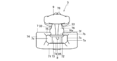
- the fuselage includes a lower blade, an upper blade facing the front portion of the lower blade, a guide pillar joining the upper blade and the lower blade, and a pair of side plates protruding upward from both left and right ends of the lower blade.
- a pair of flanges extending inwardly from the upper ends of the pair of side plates, and a ridge protruding upward from the upper blade.
- the pull tab regulates the forward and backward movement of the body by the rearward lying posture with respect to the body and deregulates the forward and backward movement of the body by the standing posture.
- the pull tab also includes a shaft having a cam portion that engages with the lock member.
- the locking member locks the front-back position of the body by contacting the pair of element rows, and maintains the lying posture and the standing posture of the puller toward the rear side in cooperation with the body.
- the body and the lock member cooperate to form a pull tab attachment portion.
- the pull tab attachment portion includes a shaft hole that supports the shaft and penetrates left and right.
- the lower surface of the shaft hole includes the upper surfaces of the raised portions and is located above the upper surfaces of the pair of flanges.
- a pair of cloth accommodating space portions is formed between the upper and lower sides of the pull tab in the laid-back posture and the pair of flanges.
- the pair of cloth storage spaces accommodates the pair of cloths fixed to the upper side of the pair of tapes and is partitioned into right and left by the raised portion.
- the range right above the upper surfaces of the pair of flanges be as follows. That is, the range directly above the upper surfaces of the pair of flanges is to include only the pair of cloth storage space portions below the pull tabs.
- the body is as follows. That is, the body is provided with a pair of branch passages of the tape groove between the pair of flanges and the upper blade. Further, the range right above the pair of branch paths is to have only the pair of cloth storage space portions below the pull tab.
- the body, the lock member, and the pull tab attachment portion be as follows. That is, the body includes a front mounting post and a rear mounting post that project upward from the raised portion with a space in the front and back. Further, the lock member is installed on the front mounting pillar and the rear mounting pillar. The pull tab attachment portion is formed by cooperation of the lock member, the front attachment pillar, the rear attachment pillar, and the raised portion.
- the pull tab has, in addition to the shaft, a pair of rods extending from both ends of the shaft in the radial direction centered on the shaft, and a knob for joining the pair of rods on the side opposite to the shaft.
- the pull tab may or may not be provided with a projecting portion that projects from the pair of rod portions on the side opposite to the knob with respect to the shaft.
- the pull tab is provided with a pair of projecting portions that respectively project from the pair of rod portions on the side opposite to the knob portion with respect to the shaft.
- the pair of protrusions sandwich the front mounting column when the pull handle is in the laid-down posture to the rear side, and collide with the front mounting column when the pull handle is tilted in the left-right direction.
- the pull tab may or may not be able to maintain the lying posture to the front side, but in order to suppress the damage of the cloth by the pull tab as much as possible, the following is desirable. That is, the raised portion is provided with a stepped portion that projects in a stepwise manner with respect to the front mounting column on the front side of the shaft hole. Then, the stepped portion collides with the pull tab that has fallen to the front side and determines the fall posture to the front side of the pull tab.
- the cam portion and the shaft hole are in surface contact with each other when the handle is in a reclining posture to the rear side.
- the slider becomes large, which is not desirable. Therefore, in order to reduce the size of the slider and minimize the portion of the pair of fabrics that appears on the front side, the following is desirable. That is, the cam portion and the shaft hole are each provided with a flat surface portion that comes into surface contact with each other in the fall posture of the puller to the rear side.
- the pull tab may include a portion located below the lower surface of the shaft hole, but in order to make the vertical dimension of the pair of fabric storage space portions as wide as possible. It is desirable to do the following. That is, the pull tab is located above the lower surface of the shaft hole when the handle is in the rearward lying position.
- the slider of the present invention is provided with a raised portion on the upper blade, and the lower surface of the shaft hole is positioned above the upper surfaces of the pair of flanges by the raised portion. Compared to the slider located below the upper surface of the flange, the pull tab is less likely to contact the pair of cloths, and damage to the pair of cloths can be suppressed.
- the slider of the present invention is provided with only a pair of material storage space portions below the pull tabs in a range directly above the upper surfaces of the pair of flanges, for example, a pair of raised portions Compared with the one projecting in a range right above the upper surface of the flange, the pull tabs are less likely to contact the pair of cloths, and damage to the pair of cloths can be suppressed.
- the slider of the present invention is provided with only a pair of cloth-accommodating space portions below the pull tabs in a range directly above the pair of branch paths, for example, the raised portion has a pair of branch portions. Compared with the one that projects to the range right above the road, the pull tabs are less likely to contact the pair of cloths, and damage to the pair of cloths can be suppressed.
- the pull tab in the case where the pull tab is provided with a pair of protrusions, the pair of protrusions sandwich the front mounting column in the backward lying posture, so that the pull tab is tilted in the left-right direction. Can be made as small as possible and the fallen posture of the puller becomes stable.
- the slider of the present invention is provided with a stepped portion in the raised portion, it is possible to hold the pair of cloth storage space portions in the fall position of the puller to the front side, and thus to prevent damage to the pair of cloth.
- the slider of the present invention when the cam portion and the shaft hole are respectively provided with the flat surface portions which are in surface contact when the pulling handle is in the rearward laying posture, for example, the pulling handle in the rearward laying posture is provided.
- the slider can be downsized and the portion that appears on the front side of the pair of fabrics can be made as small as possible.
- the puller in the rearward lying posture when the puller in the rearward lying posture is located above the lower surface of the shaft hole, for example, the puller in the rearward lying posture is below the lower surface of the shaft hole.
- the vertical dimension of the pair of dough-holding spaces can be made as wide as possible, and damage to the pair of dough can be further suppressed.
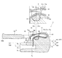
- FIG. 4 is a sectional view taken along line IV-IV in FIG. 1.
- FIG. 5 is a sectional view taken along line VV of FIG. 1.
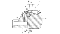
- FIG. 7 is a sectional view taken along line VII-VII of FIG. 6. It is sectional drawing which shows the fallen posture to the front side of a handle. It is a top view which shows the body before an assembly.
- the hidden slide fastener 1 includes a pair of fastener stringers 2 and 2 and a slider 3 that opens and closes the pair of fastener stringers 2 and 2.
- the pair of fastener stringers 2 and 2 includes a pair of tapes 4 and 4 that face each other, and a pair of element rows 5 and 5 that are separately fixed to the side edges of the tapes 4 and 4 that face each other. ..
- the element row 5 is formed by bending a monofilament into a coil shape, and a large number of elements for one turn of the coil are continuous.
- the hidden slide fastener 1 shown in FIG. 5 is one in which the pair of tapes 4 and 4 are folded back at opposite side edges, and the pair of element rows 5 and 5 are fixed to the folded back portions. More specifically, the pair of tapes 4 and 4 are orthogonal to the longitudinal direction and the thickness direction. The pair of tapes 4 and 4 are continuous with the pair of tape main bodies 4a and 4a on the front side and the opposite side edges of the pair of tape main bodies 4a and 4a, and the pair of tape folding-back portions that are folded back to the back side. 4b, 4b. Then, the element row 5 is fixed to the back surface side of the tape folding portion 4b by a thread (not shown).
- a pair of cloths 6, 6 to which the hidden slide fastener 1 is attached are folded back at their opposite side edges and fixed by a thread (not shown). More specifically, the pair of fabrics 6 and 6 are continuous with the pair of opposing front side fabric bodies 6a and 6a and the opposing side edges of the pair of fabric bodies 6a and 6a and are folded back to the back side. And a pair of folded back portions 6b, 6b.
- the direction is determined using three linear directions that are orthogonal to each other.
- the first linear direction is the direction in which the pair of fastener stringers 2 and 2 face each other, in other words, the direction in which the pair of element rows 5 and 5 faces each other, and is referred to as the left-right direction.
- the fastener stringer 2 (tape 4) is in the shape of a strip that is folded back so as to overlap the front and back sides, and the width direction of the strip is the left-right direction.
- the left-right direction is the left-right direction in FIG.
- the second linear direction is the longitudinal direction of the pair of fastener stringers 2, 2, that is, the direction in which the fastener stringers 2 extend, and is referred to as the front-back direction.
- the forward direction is a direction in which the slider 3 is moved when closing the pair of fastener stringers 2 and 2 (when engaging the pair of element rows 5 and 5).
- the forward direction is the direction that faces the back in the direction orthogonal to the paper surface of FIG.
- the rearward direction is a direction in which the slider 3 is moved when opening the pair of fastener stringers 2 (when separating the pair of element rows 5 and 5).
- the rearward direction is the frontward direction out of the directions orthogonal to the paper surface of FIG.
- the third linear direction is the thickness direction of the fastener stringer 2, in other words, the thickness direction of the tape 4, and is referred to as the vertical direction.
- the upward direction is the upward direction in FIG.
- the downward direction is the downward direction in FIG.
- the slider 3 of the first embodiment of the present invention includes a body 7 that guides the pair of tape folding portions 4b and 4b and the pair of element rows 5 and 5, and a pair of body 7
- a lock member 8 that can contact and separate from the element rows 5 and 5 and locks the front and rear positions of the body 7 by contact, and the body so that the lock member 8 and the body 7 can rotate in the front-rear direction.
- a pull tab 9 attached to 7.
- the pull tab 9 includes a shaft 91, a pair of rod portions 92, 92 facing each other in the extending direction of the shaft 91 and extending in the radial direction from both ends of the shaft 91, and a pair of rod portions 92, 92 on the opposite side of the shaft 91.
- a knob portion 93 that is grasped when being joined and operated, and a pair of protrusion portions 94 and 94 that protrude from the pair of rod portions 92 and 92 to the shaft 91 on the side opposite to the knob portion 93, respectively. .. As shown in FIG.
- the pull tab 9 when the pull tab 9 reaches a limit position on the front side of the rotation range, the pull tab 9 lays down relative to the body 7 and becomes a stable posture, that is, a laid posture to the front side, and is grasped with respect to the shaft 91 side. It is in a tilted state in which the side of the portion 93 is located above. Further, as shown in FIG. 4, when the pull tab 9 reaches a limit position to the rear side of the rotation range, the pull tab 9 lays down relative to the body 7 and becomes a stable posture, that is, a rearward laid posture. Further, the pull tab 9 which is in the laid-down posture to the rear side is parallel to the front-rear direction. Further, as shown in FIGS. 6 and 7, the pull tab 9 stands upright with respect to the body 7 in the middle of the rotation range and takes a stable posture, that is, a standing posture.
- the rod portion 92 and the protruding portion 94 are higher than the lower end 91B of the shaft 91 when the handle 9 is in the laid-down posture to the rear side.
- the lower end 93B of the knob portion 93 is located above the lower end 9B of the handle 9.
- part of the rod part 92 and part of the protrusion part 94 have a height lower than the lower end 91B of the shaft 91.
- the pair of rod portions 92, 92, the shaft 91 and the knob portion 93 cooperate to form an annular shape.
- a through hole 9a is formed inside the ring.
- the shaft 91 is the center when the pull tab 9 rotates, and extends in the left-right direction.
- the shaft 91 has a cam portion 91a that engages with the lock member 8 at an intermediate portion in the longitudinal direction (left-right direction) thereof. Further, the shaft 91 has a pair of left and right sides with respect to the cam portion 91a as a pair of shaft body portions 91b and 91b which are supported by a shaft hole 32 of a puller attachment portion 31 which will be described later when the pull tab 9 is rotated.
- the cam portion 91a has an outer periphery that is not constant with respect to the center line of the shaft 91. Further, as shown in FIG.
- the cam portion 91a is provided on its outer peripheral surface with a cam concave portion 91c which is recessed in the radial direction of the shaft 91 with respect to an imaginary surface extending from the outer peripheral surfaces of the pair of shaft main body portions 91b, 91b. There is.
- the fuselage 7 includes a lower blade 71, an upper blade 72 facing the center of the width of the lower blade 71 at the front of the lower blade 71, an upper blade 72 and a lower blade 71. And a guide pillar 73 extending in the vertical direction, a pair of side plates 74, 74 projecting upward from both left and right ends of the lower blade 71, and an upper end of the pair of side plates 74, 74 extending inwardly toward the left and right sides
- a pair of flanges 75, 75, a raised portion 76 protruding upward from the upper blade 72, and a front mounting column 77 and a rear mounting column 78 projecting upward at a distance from the raised portion 76 in the front-rear direction are provided.
- the portion of the body 7 that includes the lower blade 71, the upper blade 72, the guide column 73, the pair of side plates 74, 74, and the pair of flanges 75, 75 is also referred to as the body portion, and the pair of fabrics 6, 6 It is the part placed on the back side of.
- the body 7 has, as a space portion, an element path 7a that penetrates in the front-rear direction in the front-rear direction and allows the pair of element rows 5 and 5 to pass therethrough. It is provided with a tape groove 7b that allows the pair of tapes 4 and 4 to pass therethrough.
- the element path 7a includes a pair of branch paths 7c and 7c branched left and right in the front part of the body 7, and a combined path 7d in which the pair of branch paths 7c and 7c merge in the rear part of the body 7.
- the relationship between the body 7 and the element row 5 is as follows. As shown in FIG. 5, the upper surface of the lower blade 71 guides the lower side of the pair of element rows 5 and 5. Inner side surfaces (surfaces facing left and right) of the pair of side plates 74, 74 guide the left and right outer sides of the pair of element rows 5, 5. The side surface of the guide column 73 guides the left and right inner sides of the pair of element rows 5 and 5. The upper surfaces of the pair of flanges 75, 75 guide the lower side of the pair of tape bodies 4a, 4a. By the way, the upper surfaces of the pair of flanges 75, 75 are horizontal surfaces.
- the pair of tape folding portions 4b and 4b are fixed to the left and right outer sides, and nothing is fixed to the left and right inner sides.
- the lower surface of the pair of flanges 75, 75 guides the upper side of the pair of tape folding portions 4b, 4b, and the lower surface of the upper blade 72 guides the upper side of the pair of element rows 5, 5.
- the lower surface of the upper blade 72 is located below the lower surfaces of the pair of flanges 75, 75. In this way, since the body 7 guides the pair of element rows 5 and 5 and the pair of tape folding portions 4b and 4b, the postures of the pair of stringers 2 and 2 sliding in the slider 3 are stabilized. Further, in plan view, as shown in FIG.
- a joint passage 7f of the tape groove 7b is formed between the rear portions of the pair of flanges 75 and 75, and the front portion of the pair of flanges 75 and 75 and the upper blade 72 are formed. Is formed with a pair of branch paths 7e, 7e of the tape groove 7b.
- the upper blade 72 extends in the front-rear direction. As shown in FIG. 9, the front portion of the upper blade 72 is located on the front side with respect to the pair of flanges 75, 75. The rear portion of the upper blade 72 extends rearward of the guide column 73 and is present between the pair of flanges 75 and 75 and between the pair of branch passages 7e and 7e of the tape groove 7b. As shown in FIG. 4, the lower surface (lower end 72B) of the upper blade 72 is located below the lower surface (lower end 75B) of the pair of flanges 75, 75.
- the upper blade 72 and the raised portion 76 are continuous vertically, the boundary between the upper blade 72 and the raised portion 76 cannot be visually recognized, but for convenience, the upper surface (upper end 72T) of the upper blade 72 is The height should be the same as the upper surfaces (upper ends 75T, 75T) of the pair of flanges 75, 75.
- the raised portion 76 is raised above the upper surface of the upper blade 72. Therefore, the raised portion 76 is an upper portion with respect to the upper surfaces of the pair of flanges 75, 75 and a lower portion including the lower surface with respect to the lower surface of the shaft hole 32 described later.
- the raised portion 76 is formed between the pair of flanges 75, 75 in the left-right direction. More specifically, the raised portions 76 are formed within the range of the left and right ends of the upper blade 72. In other words, the raised portion 76 is formed in the range on the left and right with respect to the pair of branch paths 7e, 7e of the tape groove 7b. Further, as shown in FIG. 4, a front mounting column 77 projects from the front portion of the upper surface of the raised portion 76, and a rear mounting column 78 projects from the rear portion of the upper surface of the raised portion 76. Further, as shown in FIGS.
- the front mounting post 77 and the rear mounting post 78 are formed within the range of the left and right ends of the raised portion 76 in the left-right direction. Is formed inside.
- the raised portion 76 is formed so as to be sandwiched between the pair of projecting portions 94, 94 of the pull tab 9 with a gap. Therefore, when the pull tab 9 in the upright posture is inclined in the left-right direction, one of the pair of protrusions 94, 94 collides with the raised portion 76 and blocks it.
- the raised portion 76 as shown in FIG.
- the front mounting column 77 is sandwiched between the pair of projecting portions 94, 94 of the pull tab 9 with a gap therebetween when the pull tab 9 is in the reclining posture to the rear side. Has been formed. Therefore, even if the pull tab 9 in the laid-down posture to the rear side is inclined in the left-right direction, one of the pair of protrusions 94, 94 collides with the front mounting column 77 and blocks it. Although not the raised portion 76, the front mounting column 77 is formed so as to be sandwiched by the pair of rod portions 92, 92 of the pull tab 9 with a gap when the pull tab 9 is in the laid-down posture to the front side.
- the pair of rod portions 92, 92 collide with the front mounting column 77 and prevent it.
- the front mounting column 77 is formed rearward of the front end of the raised portion 76 in the front direction. Therefore, the raised portion 76 is provided with a stepped portion 76a that projects in a stepwise manner toward the front side with respect to the front mounting column 77.
- the stepped portion 76 a is raised above the lower surface of the shaft hole 32 on the front side of the front mounting column 77.
- the stepped portion 76 a also projects in a stepped manner on both left and right sides of the front mounting column 77. Moreover, the stepped portion 76a also protrudes to the left and right sides in a stepwise manner with respect to the portion between the front mounting pillar 77 and the rear mounting pillar 78. Then, the pull tab 9 which is laid down on the front side is placed on the step portion 76a.
- the stepped portion 76a is formed to have the highest portion on the front side of the front mounting column 77, and when the pull tab 9 lying on the front side comes into contact with the front portion, the limit position of the pull tab 9 to the front side is limited. Is determined, and the pull tab 9 is in a lying posture to the front side.
- the front mounting column 77 is provided with a front housing groove 77a for housing the front portion of the lock member 8 in the center of the width of the upper surface thereof.
- the front mounting column 77 forms a front bottom portion 77b that forms the bottom surface of the front accommodation groove 77a and left and right side surfaces of the front accommodation groove 77a, and a pair of front side wall portions 77c that protrudes upward from the left and right sides of the front bottom portion 77b.
- 77c, and a pair of front convex portions 77d, 77d that respectively project inward in the left and right so as to approach from the upper ends of the pair of front side wall portions 77c, 77c and cover the front portion of the lock member 8 from above.
- the rear mounting column 78 has a rear accommodation groove 78a for accommodating the rear portion of the lock member 8 at the center of the width of the upper surface thereof.
- the rear mounting column 78 forms a rear bottom portion 78b forming the bottom surface of the rear accommodation groove 78a, and left and right side surfaces of the rear accommodation groove 78a and a pair of rear side wall portions 78c protruding upward from both left and right sides of the rear bottom portion 78b.
- 78c and a pair of rear convex portions 78d, 78d that respectively project inward in the left and right so as to approach from the upper ends of the pair of rear side wall portions 78c, 78c.
- the raised portion 76, the front mounting pillar 77, and the rear mounting pillar 78 cooperate with each other to form an opening (reference numeral omitted) that penetrates in the left-right direction and opens in the upward direction.
- the upper side of this opening is covered with a lock member 8 which is provided above the upper part of the front mounting column 77 and the upper part of the rear mounting column 78, as shown in FIGS. Then, the opening and the lock member 8 form a pull tab attachment portion 31 for attaching (connecting) the pull tab 9 to the body 7.
- the pull tab attachment portion 31 is ring-shaped when viewed from the side, and has a shaft hole 32 for supporting the shaft 91 of the pull tab 9 inside the ring.
- the shaft hole 32 penetrates in the left-right direction.
- the shaft hole 32 and the cam portion 91a are provided with flat surface portions 32a and 91d, respectively, which are in surface contact with each other.
- the flat surface portion 32 a of the shaft hole 32 is the lower surface of the shaft hole 32 and the upper surface between the front mounting column 77 and the rear mounting column 78.
- the flat surface portion 91d of the cam portion 91a is a lower surface portion in the case where the pull tab 9 is in a reclining posture to the rear side.
- the plane portion 32a of the shaft hole 32 and the plane portion 91d of the cam portion 91a are planes orthogonal to each other in the vertical direction.
- the lower surface of the shaft hole 32 (upper surface of the raised portion 76) is a surface on which the shaft 91 of the pull tab 9 (the flat surface portion 91d of the cam portion 91a) rests.
- the flat surface portion 91d (the lower end 91B of the shaft 91) of the cam portion 91a of the pull tab 9 is placed on the upper surface (upper end 76T) of the raised portion 76 in an overlapping manner.
- the lower end of the pull tab 9 which is in the laid-down posture to the rear side is the shaft 91. Therefore, the pull tab 9 in the rearward lying position is located above the lower surface of the shaft hole 32.
- the grip portion 93 of the pull tab 9 in the rearward lying position is located above the lower surface of the shaft 91 in consideration of operability. Therefore, when the pull tab 9 is in the laid-down posture to the rear side, the lower end 93B of the knob portion 93 is located above the flat surface portion 91d of the cam portion 91a of the pull tab 9. Further, when the pull tab 9 is in the laid-down posture to the rear side, the lower end 93B of the knob portion 93 is a line parallel to the lower end 91B of the flat surface portion 91d of the cam portion 91a of the pull tab 9 and the cam portion of the pull tab 9. An imaginary line located above the lower end 91B of the plane portion 91d of 91a is defined. A cloth storage space 33, which will be described later, is formed between the virtual line and the upper surfaces of the flanges 75, 75.
- cam portion 91a is provided with another flat surface portion 91e on the front side with respect to the flat surface portion 91d in the case of the reclining posture of the pull tab 9 to the rear side.
- the plane portion 91e is a plane orthogonal to the front-rear direction and stabilizes the standing posture of the pull tab 9, as shown in FIG.
- the lower surface of the shaft hole 32 is the upper surface of the raised portion 76 and is located above the upper surface of the flange 75.
- the raised portion 76 is formed to have a thickness such that its upper surface (lower surface of the shaft hole 32) is located above the upper surface of the flange 75.
- a pair of cloth storage spaces 33, 33 for storing the pair of cloths 6, 6 are provided on the left and right sides of the raised portion 76. Is formed in the formed state.
- the upper limit position of the material storage space 33 is determined by the lower surface of the pull tab 9.
- the lower limit position of the cloth storage space 33 is determined by the upper surfaces of the pair of flanges 75, 75 and the upper surfaces of the pair of branch passages 7e, 7e of the tape groove 7b.
- the heights of the upper surfaces of the pair of branch passages 7e, 7e are supposed to match the upper surfaces (upper ends 75T) of the pair of flanges 75, 75.
- the laterally inner limit position of the dough storage space 33 is defined by the lateral side surface of the raised portion 76.
- the upper range 75R, 75R with respect to the upper surfaces of the pair of flanges 75, 75 is provided with only the pair of cloth accommodating space portions 33, 33 below the pull tab 9.
- the above-mentioned ranges 75R, 75R are provided with only the pair of dough storage spaces 33, 33 between the upper ends 75T of the pair of flanges 75, 75 and the lower end 9B of the pull tab 9. Therefore, only the pull tab 9 exists in the range 75R, 75R directly above the upper surfaces of the pair of flanges 75, 75. Therefore, when the slider 3 is not attached to the fastener stringer 2, the pull tab 9 and the upper surfaces of the flanges 75, 75 face each other in the upper range 75R, 75R with the pull tab 9 lying down.
- the raised portion 76 does not exist in the range 75R, 75R directly above the upper surfaces of the pair of flanges 75, 75.
- the upper ranges 7R and 7R with respect to the pair of branch passages 7e and 7e are provided with only the pair of dough storage space portions 33 and 33 below the pull tab 9. This is because the raised portions 76 are formed within the range of the left and right ends of the upper blade 72 as described above. Therefore, the puller 9 is the only tangible object existing in the range 7R, 7R immediately above the upper surfaces of the pair of branch paths 7e, 7e. Further, the raised portion 76 does not exist in the areas 7R and 7R directly above the upper surfaces of the pair of branch paths 7e and 7e.
- the tape main body 4a is arranged above the flange 75, not only the cloth 6 but also the tape main body 4a is stored in the cloth storage space 33. More specifically, the dough accommodating space 33 accommodates the dough 6 that is doubled by folding back the opposite side edges and the tape body 4a located on the upper surface side of the flange 75.
- the vertical distance between the pair of cloth storage spaces 33, 33 is the vertical distance between the pull tab 9 and the pair of flanges 75, 75, and the shortest distance is preferably set to 2 mm or more. Incidentally, when the pull tab 9 is in the upright posture as shown in FIG. 7, the pair of protrusions 94, 94 are located below the shaft 91, and as shown in FIG.
- the lower end 91B of the shaft 91, the lower ends of the pair of rods 92, 92 and the lower ends of the pair of protrusions 94, 94 are all at the same height, and as shown in FIG.
- the lower ends of the pair of protrusions 94, 94 and the lower ends of the pair of rods 92, 92 are located below the lower end 91B of the shaft 91.
- the material storage space 33 is set to 2 mm or more.
- the pair of cloth storage space portions 33, 33 are symmetrical.
- the portions are respectively provided with first slopes 95, 95 that are directed upward as they are separated from the shaft 91.
- the first slope 95 is also formed continuously with the protrusion 94.
- Second slopes 96, 96 are formed so as to extend upward as they are separated from 91.
- the pair of second slopes 96, 96 are also formed continuously with the pair of rod portions 92, 92.
- the lock member 8 locks the front-rear position of the body 7 with respect to the pair of element rows 5 and 5 by contacting the pair of element rows 5 and 5 as described above, and conversely, the pair of element rows 5 and 5 is locked.
- the front and rear positions of the body 7 with respect to the pair of element rows 5 and 5 are unlocked by separating them from each other.
- the lock member 8 is a so-called plate spring, which is formed by bending a metal plate into a predetermined shape.
- the lock member 8 includes an upper plate 81 and a lower plate 82 which are vertically opposed to each other, a joining plate 83 which joins the front ends of the upper plate 81 and the lower plate 82, and a lower end of the upper plate 81.
- An insertion plate 84 that extends into the rear mounting groove 78a of the rear mounting column 78 and a claw plate 85 that extends downward from the rear end of the lower plate 82.
- the joint plate 83 has a shape that bulges toward the front, more specifically, an arc shape.
- the upper plate 81 has a shape in which the middle in the front-rear direction is located above a virtual straight line connecting both ends in the front-rear direction.
- the upper plate 81 is a curved plate when viewed from the side. More specifically, when viewed from the side, the upper plate 81 has a front portion and a rear portion of the entire length in the front-rear direction which are straight portions, and the middle portion in the front-rear direction is smoothly continuous with the front-rear linear portions being curved. It is a curved portion. Further, the rear straight line portion is located below the imaginary straight line that extends the front straight line portion rearward. Further, the tangential directions of the front and rear ends of the curved portion coincide with the extending directions of the front and rear straight portions.
- the front part of the upper plate 81 is housed in the front housing groove 77a, the left and right sides and the lower side thereof are supported by the pair of front side wall parts 77c, 77c, and the upper side thereof is pressed by the pair of front convex parts 77d, 77d. There is.
- the lower portions of the pair of front side wall portions 77c, 77c respectively project toward the left and right inner sides with respect to the upper portions of the pair of front side wall portions 77c, 77c. , 77e.
- An upper plate 81 is placed on the pair of shelves 77e, 77e.
- the upper side of the upper plate 81 is pressed by not only the pair of front convex portions 77d and 77d but also the pair of front side wall portions 77c and 77c. Therefore, as shown in FIG. 5, the upper end portions of the pair of front side wall portions 77c, 77c are bent so as to cover the upper plate 81 from above from below.
- the lower plate 82 also has a shape in which the middle in the front-rear direction is located above a virtual straight line connecting both ends in the front-rear direction.
- the lower plate 82 is a bent plate when viewed from the side. More specifically, when viewed from the side, the lower plate 82 has a front portion and a rear portion in the front-rear direction which are straight portions, and the front straight portion and the rear straight portion are continuous in a bent state.
- the straight part of the front part of the lower plate 82 goes downward as it goes forward.
- the straight portion of the rear portion of the lower plate 82 goes downward as it goes backward.
- the lower plate 82 is placed on the cam portion 91a of the shaft 91 of the pull tab 9 and presses the cam portion 91a from above by its restoring force. Further, in the case of the laid posture of the pull tab 9 to the rear side, the lower plate 82 presses the cam concave portion 91c which is the upper surface of the shaft 91 from above, and stabilizes the laid posture of the shaft 91 and thus the pull tab 9. Further, when the posture of the pull tab 9 is a posture between the rearward lying posture and the standing posture, the lower plate 82 presses the cam portion 91a from above by its restoring force, and the pull tab 9 is placed in the rear lying posture. Push in so that Even when the pull tab 9 is in the upright posture and the frontward lying posture, the lower plate 82 presses the cam portion 91a from above by its restoring force and stabilizes those postures.
- the tip part (lower part) of the claw plate 85 projects into the element path 7 a of the body 7. Therefore, the rear mounting column 78, the raised portion 76, and the upper blade 72 are provided with a claw hole 7h which communicates with the rear accommodation groove 78a and the element passage 7a (combining passage 7d) and penetrates in the vertical direction.
- the claw plate 85 is housed in the claw hole 7h.
- the amount (length) of the tip of the claw plate 85 protruding into the element path 7a changes depending on how the lower plate 82 of the lock member 8 and the cam portion 91a of the shaft 91 are engaged. As shown in FIG.
- the insertion plate 84 is housed rearward in the rear housing groove 78a with respect to the claw hole 7h.
- the slider 3 of the first embodiment described above has the following effects.
- the slider 3 controls or deregulates the movement of the body 7 in the front-rear direction depending on the standing posture of the pull tab 9 with respect to the body 7, the frontward lying posture, and the rearward lying posture. Further, as shown in FIGS. 4 and 5, the slider 3 is provided with the raised portion 76 on the upper blade 72 so that the vertical distance between the pull tab 9 and the pair of flanges 75, 75 is widened. Since the slider 3 has the pair of cloth-holding spaces 33, 33 partitioned left and right by the raised portion 76 between the upper and lower sides of the pull tab 9 and the pair of flanges 75, 75, the slider 3 has a pair of cloths 6, 6.
- the pull tab 9, the front mounting pillar 77, the rear mounting pillar 78, and the lock member 8 appear on the front side. Further, in the slider 3, since the lower surface of the shaft hole 32 is located above the upper surfaces of the pair of flanges 75, 75 by the raised portion 76, the pair of cloth containing space portions 33, 33 are formed, so that, for example, the shaft hole is formed. Compared with the slider whose lower surface is positioned below the upper surfaces of the pair of flanges, the pull tab 9 is less likely to contact the pair of cloths 6 and 6, and damage to the pair of cloths 6 and 6 can be suppressed.
- the pull tab 9 does not contact the pair of fabrics 6 and 6 is to prevent the restriction of the movement of the slider 3 in the front-rear direction from being released. If the pull tab 9 comes into contact with the pair of fabrics 6 and 6, the pull tab 9 approaches an upright posture, the tip of the claw plate 85 does not project into the element path 7a, and the regulation of the movement of the slider 3 in the front-rear direction is released.
- the slider 3 is provided with only the pair of cloth accommodating space portions 33, 33 below the pull tab 9 in the ranges 75R, 75R directly above the upper surfaces of the pair of flanges 75, 75, for example, the raised portion Comparing with 76 in which the upper surface of the pair of flanges 75, 75 overhangs in the range 75R, 75R directly above, the pull tab 9 is less likely to contact the pair of fabrics 6, 6, and the pair of fabrics 6, 6 is damaged. Can be suppressed. More specifically, the slider 3 is provided with only the pair of material storage space portions 33, 33 below the pull tab 9 in the range directly above the pair of branch paths 7e, 7e. Is less likely to contact the pair of cloths 6,6 than the pair of branch paths 7e,7e that are projected right above the ranges 7R,7R, and damage of the pair of cloths 6,6 is suppressed. To be
- the slider 3 is provided with the flat portions 91d and 32a, which are in surface contact with each other when the cam portion 91a and the shaft hole 32 are in the rearward laid posture of the pull tab 9, for example, the rear laid posture of the pull tab is maintained.
- the slider 3 can be downsized and the portion that appears on the front side with respect to the pair of fabrics 6 and 6 can be made as small as possible.
- the slider 3 is arranged such that the pull tab 9 in the rearwardly lying posture is located above the lower surface of the shaft hole 32, the slider 3 in the rearward lying posture (more specifically, the lower surface of the puller) is used as an axis.
- the vertical dimension of the pair of fabric storage space portions 33, 33 can be made as wide as possible, and the pull tab 9 can be used for the pair of fabrics 6.
- 6 is less likely to contact, and as a result, damage to the pair of fabrics 6, 6 can be further suppressed.
- the pair of first slopes 95, 95 widen the pair of cloth storage spaces 33, 33, so that the pair of cloths 6, 6 can be further prevented from being damaged.
- the pair of projecting portions 94 and 94 sandwich the front mounting column 77 with a gap therebetween when the pull tab 9 is tilted to the left and right when the pull tab 9 is tilted rearward.
- the one of the protrusions 94 collides with the front mounting column 77, whereby the inclination of the pull tab 9 in the left-right direction can be made as small as possible, and the fall posture of the pull tab 9 to the rear side becomes stable.
- the pull tab 9 is placed on the stepped portion 76a when the pull tab 9 is in the front lying posture, the pull posture of the pull tab 9 to the front side is stable, and the pair of cloth accommodating spaces Since the parts 33, 33 can be held, damage to the pair of fabrics 6, 6 can be suppressed. Moreover, the pair of second slopes 96, 96 widen the pair of dough-holding spaces 33, 33, so that damage to the pair of doughs 6, 6 can be further suppressed. Further, since the slider 3 is such that the front end portion of the pull tab 9 is located above the lower end of the shaft 91 when the pull tab 9 is in the laid-down posture to the front side, the pull tab 9 is positioned more than the pair of cloth storage space portions 33, 33.
- the pull tab 9 Since the front end portion of the handle 9 is raised, the pull tab 9 can be easily operated. Further, in the slider 3, the pair of rod portions 92, 92 of the pull tab 9 sandwiches the front mounting column 77 with a gap therebetween when the pull tab 9 is in the lying position to the front side. Then, the pair of rods 92, 92 collide with the front mounting column 77, whereby the tilt of the pull tab 9 in the left-right direction can be minimized, and the fall posture of the pull tab 9 to the front side becomes stable.
- the slider 3 fixes both the front portion and the rear portion of the lock member 8 to the body 7 and supports the pull tab 9 only by the pull tab mounting portion 31, but the present invention is not limited to this.
- the front part of the lock member is fixed to the body, the rear part is held so as to be displaceable in the vertical direction, and the puller is supported by the pair of reinforcing parts and the puller mounting part formed on the left and right with respect to the puller mounting part. It may be one.
- the lock member is not bent so as to face each other in the vertical direction but is bent in the vertical direction from the front portion to the rear portion of the body.
- the pull tab attaching portion is formed by the raised portion and the lock member.
- each reinforcing portion is provided with a pair of column portions protruding upward from the upper wing plate with a front-rear interval left or right with respect to the pull tab attachment portion.
- the upper part of the pair of pillars is plastically deformed so as to approach each other, so that the distance between the upper parts of the pair of pillars becomes smaller than the diameter of the shaft. , Thereby preventing the shaft from moving upward relative to the pair of posts.
Landscapes
- Slide Fasteners (AREA)
Abstract
La présente invention vise à réduire au minimum des dommages causés à une paire de tissus autant que possible en verrouillant des positions avant et arrière d'un corps lorsqu'une tirette est dans une position repliée, et en libérant le verrouillage lorsque la tirette est dans une position verticale. Le curseur pour une fermeture à glissière cachée selon la présente invention comprend un corps, une tirette et un élément de verrouillage. Le corps comprend : une plaque d'aile inférieure ; une plaque d'aile supérieure ; une colonne de guidage ; une paire de plaques latérales qui font saillie vers le haut à partir des côtés droit et gauche de la plaque d'aile inférieure ; une paire de brides qui s'étendent vers l'intérieur sur la droite et la gauche à partir d'extrémités supérieures respectives de la paire de plaques latérales ; et une partie surélevée qui s'élève vers le haut à partir de la plaque d'aile supérieure. Le corps et l'élément de verrouillage fonctionnent conjointement pour former une partie de fixation de tirette. La partie de fixation de tirette comprend un trou d'arbre qui pénètre dans la partie de fixation de tirette dans la direction droite-gauche. Le trou d'arbre a une surface inférieure qui englobe la surface supérieure de la partie surélevée et qui est positionnée plus haut que les surfaces supérieures de la paire de brides. Il y a, formée dans un espace vertical entre la tirette dans une position pliée vers l'arrière et la paire de brides, une paire d'espaces de réception de tissu qui est destinée à recevoir la paire de tissus fixée sur le dessus d'une paire de bandes et qui est séparée en gauche et droite par la partie surélevée.
Priority Applications (7)
| Application Number | Priority Date | Filing Date | Title |
|---|---|---|---|
| PCT/JP2019/004350 WO2020161848A1 (fr) | 2019-02-07 | 2019-02-07 | Curseur pour une fermeture à glissière cachée |
| JP2020570281A JP7045491B2 (ja) | 2019-02-07 | 2019-02-07 | 隠しスライドファスナー用スライダー |
| EP19914378.5A EP3922125B1 (fr) | 2019-02-07 | 2019-02-07 | Curseur pour une fermeture à glissière cachée |
| CN202010082797.XA CN111150181B (zh) | 2019-02-07 | 2020-02-07 | 隐形拉链用拉头 |
| CN202020157007.5U CN211833155U (zh) | 2019-02-07 | 2020-02-07 | 隐形拉链用拉头 |
| TW109103797A TWI717993B (zh) | 2019-02-07 | 2020-02-07 | 隱形拉鏈用滑件 |
| US17/392,502 US11419393B2 (en) | 2019-02-07 | 2021-08-03 | Slider for concealed slide fastener |
Applications Claiming Priority (1)
| Application Number | Priority Date | Filing Date | Title |
|---|---|---|---|
| PCT/JP2019/004350 WO2020161848A1 (fr) | 2019-02-07 | 2019-02-07 | Curseur pour une fermeture à glissière cachée |
Related Child Applications (1)
| Application Number | Title | Priority Date | Filing Date |
|---|---|---|---|
| US17/392,502 Continuation US11419393B2 (en) | 2019-02-07 | 2021-08-03 | Slider for concealed slide fastener |
Publications (1)
| Publication Number | Publication Date |
|---|---|
| WO2020161848A1 true WO2020161848A1 (fr) | 2020-08-13 |
Family
ID=70565360
Family Applications (1)
| Application Number | Title | Priority Date | Filing Date |
|---|---|---|---|
| PCT/JP2019/004350 Ceased WO2020161848A1 (fr) | 2019-02-07 | 2019-02-07 | Curseur pour une fermeture à glissière cachée |
Country Status (6)
| Country | Link |
|---|---|
| US (1) | US11419393B2 (fr) |
| EP (1) | EP3922125B1 (fr) |
| JP (1) | JP7045491B2 (fr) |
| CN (2) | CN211833155U (fr) |
| TW (1) | TWI717993B (fr) |
| WO (1) | WO2020161848A1 (fr) |
Families Citing this family (2)
| Publication number | Priority date | Publication date | Assignee | Title |
|---|---|---|---|---|
| WO2020161848A1 (fr) | 2019-02-07 | 2020-08-13 | Ykk株式会社 | Curseur pour une fermeture à glissière cachée |
| CN116616537B (zh) * | 2023-06-29 | 2025-09-16 | 潍坊中传拉链配件有限公司 | 一种拉链及其拉头 |
Citations (6)
| Publication number | Priority date | Publication date | Assignee | Title |
|---|---|---|---|---|
| JPS6125013B2 (fr) | 1976-08-13 | 1986-06-13 | Bayer Ag | |
| JPH10234429A (ja) * | 1997-02-28 | 1998-09-08 | Ykk Corp | 隠しスライドファスナー用スライダー |
| JP2009000145A (ja) * | 2007-06-19 | 2009-01-08 | Kawashima Selkon Textiles Co Ltd | 隠しスライドファスナ |
| WO2016027340A1 (fr) * | 2014-08-21 | 2016-02-25 | Ykk株式会社 | Glissière pour fermeture à glissière |
| WO2016092637A1 (fr) | 2014-12-09 | 2016-06-16 | Ykk株式会社 | Glissière pour fermeture à glissière, et son procédé de fabrication |
| JP2018089450A (ja) * | 2018-03-09 | 2018-06-14 | Ykk株式会社 | スライドファスナー用スライダー及びスライドファスナー |
Family Cites Families (14)
| Publication number | Priority date | Publication date | Assignee | Title |
|---|---|---|---|---|
| US3011238A (en) * | 1958-11-03 | 1961-12-05 | Irving Constant | Concealed slide fastener and cloth article containing the same |
| US3138852A (en) * | 1961-12-26 | 1964-06-30 | Talon Inc | Automatic lock slider assembling machine |
| US3099059A (en) * | 1962-01-05 | 1963-07-30 | Scovill Manufacturing Co | Spring-locking slider for zipper fasteners |
| DE2540201C2 (de) * | 1975-09-10 | 1979-05-31 | Opti Patent-, Forschungs- Und Fabrikations-Ag, Glarus (Schweiz) | Reißverschluß |
| TW517536U (en) * | 2001-05-30 | 2003-01-11 | Chung Chwan Entpr Co Ltd | Slider structure of hidden zipper |
| JP4244024B2 (ja) | 2004-07-05 | 2009-03-25 | Ykk株式会社 | 隠しスライドファスナー用スライダーと隠しスライドファスナー |
| CN101953547B (zh) * | 2009-07-17 | 2012-03-21 | 福建浔兴拉链科技股份有限公司 | 自锁式隐形拉头 |
| TWI488593B (zh) * | 2013-02-06 | 2015-06-21 | Ykk Corp | A slide fastener and a zipper having the slider |
| CN105377071B (zh) | 2013-07-11 | 2018-06-01 | Ykk株式会社 | 拉链用拉头 |
| WO2016135903A1 (fr) * | 2015-02-25 | 2016-09-01 | Ykk株式会社 | Curseur destiné à des fermetures à glissière |
| CN206641468U (zh) * | 2017-04-14 | 2017-11-17 | Ykk株式会社 | 拉链的拉头 |
| WO2019016900A1 (fr) * | 2017-07-19 | 2019-01-24 | Ykk株式会社 | Curseur pour fermeture à glissière |
| WO2020161848A1 (fr) * | 2019-02-07 | 2020-08-13 | Ykk株式会社 | Curseur pour une fermeture à glissière cachée |
| TWI678981B (zh) * | 2019-04-03 | 2019-12-11 | 中傳企業股份有限公司 | 拉鍊頭組合結構 |
-
2019
- 2019-02-07 WO PCT/JP2019/004350 patent/WO2020161848A1/fr not_active Ceased
- 2019-02-07 JP JP2020570281A patent/JP7045491B2/ja active Active
- 2019-02-07 EP EP19914378.5A patent/EP3922125B1/fr active Active
-
2020
- 2020-02-07 TW TW109103797A patent/TWI717993B/zh active
- 2020-02-07 CN CN202020157007.5U patent/CN211833155U/zh not_active Withdrawn - After Issue
- 2020-02-07 CN CN202010082797.XA patent/CN111150181B/zh active Active
-
2021
- 2021-08-03 US US17/392,502 patent/US11419393B2/en active Active
Patent Citations (7)
| Publication number | Priority date | Publication date | Assignee | Title |
|---|---|---|---|---|
| JPS6125013B2 (fr) | 1976-08-13 | 1986-06-13 | Bayer Ag | |
| JPH10234429A (ja) * | 1997-02-28 | 1998-09-08 | Ykk Corp | 隠しスライドファスナー用スライダー |
| JP2009000145A (ja) * | 2007-06-19 | 2009-01-08 | Kawashima Selkon Textiles Co Ltd | 隠しスライドファスナ |
| WO2016027340A1 (fr) * | 2014-08-21 | 2016-02-25 | Ykk株式会社 | Glissière pour fermeture à glissière |
| JP6273371B2 (ja) | 2014-08-21 | 2018-01-31 | Ykk株式会社 | スライドファスナー用スライダー |
| WO2016092637A1 (fr) | 2014-12-09 | 2016-06-16 | Ykk株式会社 | Glissière pour fermeture à glissière, et son procédé de fabrication |
| JP2018089450A (ja) * | 2018-03-09 | 2018-06-14 | Ykk株式会社 | スライドファスナー用スライダー及びスライドファスナー |
Non-Patent Citations (1)
| Title |
|---|
| See also references of EP3922125A4 |
Also Published As
| Publication number | Publication date |
|---|---|
| US11419393B2 (en) | 2022-08-23 |
| TWI717993B (zh) | 2021-02-01 |
| JP7045491B2 (ja) | 2022-03-31 |
| CN111150181A (zh) | 2020-05-15 |
| CN111150181B (zh) | 2022-12-06 |
| EP3922125A1 (fr) | 2021-12-15 |
| JPWO2020161848A1 (ja) | 2021-09-30 |
| EP3922125B1 (fr) | 2024-01-10 |
| TW202037305A (zh) | 2020-10-16 |
| US20210361035A1 (en) | 2021-11-25 |
| EP3922125A4 (fr) | 2022-03-09 |
| CN211833155U (zh) | 2020-11-03 |
Similar Documents
| Publication | Publication Date | Title |
|---|---|---|
| KR890000984B1 (ko) | 슬라이드 파스너용 자동 잠금 슬라이더 | |
| CN100506102C (zh) | 隐蔽型拉链用滑块和隐蔽型拉链 | |
| JP5474073B2 (ja) | 隠しスライドファスナー用スライダー | |
| CA2795095C (fr) | Fixation a glissiere | |
| US20050278904A1 (en) | Opener for slide fastener | |
| WO2020161848A1 (fr) | Curseur pour une fermeture à glissière cachée | |
| JP2007135722A (ja) | 隠しスライドファスナー用スライダー | |
| US4232430A (en) | Device for connecting the ends of a separable zipper | |
| US5528802A (en) | Lockable slider for slide fasteners | |
| US4271567A (en) | Automatic lock slider for slide fastener | |
| US2146691A (en) | Separable fastener | |
| US20090260197A1 (en) | Slider for concealed type slide fastener | |
| TW201347694A (zh) | 拉鏈滑件及拉鏈 | |
| JP6706721B2 (ja) | スライドファスナー | |
| JP3210483U (ja) | スライドファスナーのスライダー | |
| CN222982584U (zh) | 拉链用拉头 | |
| JPH08254205A (ja) | 板部材同士の連結装置 | |
| JP7833361B2 (ja) | スライダーおよびスライドファスナー | |
| JP2005273021A (ja) | 掛止具、衣料、掛止具の配設方法 | |
| US1773150A (en) | Slider for fasteners | |
| KR101922342B1 (ko) | 지퍼 슬라이더 | |
| KR20250151515A (ko) | 파스너 스트링거 및 슬라이드 파스너 | |
| JP2025036399A (ja) | 被覆物の接続構造及びキャリア | |
| WO2021117178A1 (fr) | Fermeture à glissière | |
| HK1084306B (en) | Slider for concealed type slide fastener and concealed type slide fastener |
Legal Events
| Date | Code | Title | Description |
|---|---|---|---|
| 121 | Ep: the epo has been informed by wipo that ep was designated in this application |
Ref document number: 19914378 Country of ref document: EP Kind code of ref document: A1 |
|
| ENP | Entry into the national phase |
Ref document number: 2020570281 Country of ref document: JP Kind code of ref document: A |
|
| NENP | Non-entry into the national phase |
Ref country code: DE |
|
| ENP | Entry into the national phase |
Ref document number: 2019914378 Country of ref document: EP Effective date: 20210907 |