WO2020161977A1 - 動力伝達装置 - Google Patents
動力伝達装置 Download PDFInfo
- Publication number
- WO2020161977A1 WO2020161977A1 PCT/JP2019/044220 JP2019044220W WO2020161977A1 WO 2020161977 A1 WO2020161977 A1 WO 2020161977A1 JP 2019044220 W JP2019044220 W JP 2019044220W WO 2020161977 A1 WO2020161977 A1 WO 2020161977A1
- Authority
- WO
- WIPO (PCT)
- Prior art keywords
- gear
- planetary reduction
- reduction gear
- motor
- power transmission
- Prior art date
- Legal status (The legal status is an assumption and is not a legal conclusion. Google has not performed a legal analysis and makes no representation as to the accuracy of the status listed.)
- Ceased
Links
Images

Classifications
-
- F—MECHANICAL ENGINEERING; LIGHTING; HEATING; WEAPONS; BLASTING
- F16—ENGINEERING ELEMENTS AND UNITS; GENERAL MEASURES FOR PRODUCING AND MAINTAINING EFFECTIVE FUNCTIONING OF MACHINES OR INSTALLATIONS; THERMAL INSULATION IN GENERAL
- F16H—GEARING
- F16H37/00—Combinations of mechanical gearings, not provided for in groups F16H1/00 - F16H35/00
- F16H37/02—Combinations of mechanical gearings, not provided for in groups F16H1/00 - F16H35/00 comprising essentially only toothed or friction gearings
- F16H37/06—Combinations of mechanical gearings, not provided for in groups F16H1/00 - F16H35/00 comprising essentially only toothed or friction gearings with a plurality of driving or driven shafts; with arrangements for dividing torque between two or more intermediate shafts
- F16H37/08—Combinations of mechanical gearings, not provided for in groups F16H1/00 - F16H35/00 comprising essentially only toothed or friction gearings with a plurality of driving or driven shafts; with arrangements for dividing torque between two or more intermediate shafts with differential gearing
- F16H37/0806—Combinations of mechanical gearings, not provided for in groups F16H1/00 - F16H35/00 comprising essentially only toothed or friction gearings with a plurality of driving or driven shafts; with arrangements for dividing torque between two or more intermediate shafts with differential gearing with a plurality of driving or driven shafts
- F16H37/0813—Combinations of mechanical gearings, not provided for in groups F16H1/00 - F16H35/00 comprising essentially only toothed or friction gearings with a plurality of driving or driven shafts; with arrangements for dividing torque between two or more intermediate shafts with differential gearing with a plurality of driving or driven shafts with only one input shaft
- F16H37/082—Combinations of mechanical gearings, not provided for in groups F16H1/00 - F16H35/00 comprising essentially only toothed or friction gearings with a plurality of driving or driven shafts; with arrangements for dividing torque between two or more intermediate shafts with differential gearing with a plurality of driving or driven shafts with only one input shaft and additional planetary reduction gears
-
- B—PERFORMING OPERATIONS; TRANSPORTING
- B60—VEHICLES IN GENERAL
- B60K—ARRANGEMENT OR MOUNTING OF PROPULSION UNITS OR OF TRANSMISSIONS IN VEHICLES; ARRANGEMENT OR MOUNTING OF PLURAL DIVERSE PRIME-MOVERS IN VEHICLES; AUXILIARY DRIVES FOR VEHICLES; INSTRUMENTATION OR DASHBOARDS FOR VEHICLES; ARRANGEMENTS IN CONNECTION WITH COOLING, AIR INTAKE, GAS EXHAUST OR FUEL SUPPLY OF PROPULSION UNITS IN VEHICLES
- B60K1/00—Arrangement or mounting of electrical propulsion units
-
- H—ELECTRICITY
- H02—GENERATION; CONVERSION OR DISTRIBUTION OF ELECTRIC POWER
- H02K—DYNAMO-ELECTRIC MACHINES
- H02K7/00—Arrangements for handling mechanical energy structurally associated with dynamo-electric machines, e.g. structural association with mechanical driving motors or auxiliary dynamo-electric machines
- H02K7/006—Structural association of a motor or generator with the drive train of a motor vehicle
-
- H—ELECTRICITY
- H02—GENERATION; CONVERSION OR DISTRIBUTION OF ELECTRIC POWER
- H02K—DYNAMO-ELECTRIC MACHINES
- H02K7/00—Arrangements for handling mechanical energy structurally associated with dynamo-electric machines, e.g. structural association with mechanical driving motors or auxiliary dynamo-electric machines
- H02K7/10—Structural association with clutches, brakes, gears, pulleys or mechanical starters
- H02K7/116—Structural association with clutches, brakes, gears, pulleys or mechanical starters with gears
-
- B—PERFORMING OPERATIONS; TRANSPORTING
- B60—VEHICLES IN GENERAL
- B60K—ARRANGEMENT OR MOUNTING OF PROPULSION UNITS OR OF TRANSMISSIONS IN VEHICLES; ARRANGEMENT OR MOUNTING OF PLURAL DIVERSE PRIME-MOVERS IN VEHICLES; AUXILIARY DRIVES FOR VEHICLES; INSTRUMENTATION OR DASHBOARDS FOR VEHICLES; ARRANGEMENTS IN CONNECTION WITH COOLING, AIR INTAKE, GAS EXHAUST OR FUEL SUPPLY OF PROPULSION UNITS IN VEHICLES
- B60K1/00—Arrangement or mounting of electrical propulsion units
- B60K2001/001—Arrangement or mounting of electrical propulsion units one motor mounted on a propulsion axle for rotating right and left wheels of this axle
-
- F—MECHANICAL ENGINEERING; LIGHTING; HEATING; WEAPONS; BLASTING
- F16—ENGINEERING ELEMENTS AND UNITS; GENERAL MEASURES FOR PRODUCING AND MAINTAINING EFFECTIVE FUNCTIONING OF MACHINES OR INSTALLATIONS; THERMAL INSULATION IN GENERAL
- F16H—GEARING
- F16H1/00—Toothed gearings for conveying rotary motion
- F16H1/28—Toothed gearings for conveying rotary motion with gears having orbital motion
- F16H1/46—Systems consisting of a plurality of gear trains each with orbital gears, i.e. systems having three or more central gears
-
- F—MECHANICAL ENGINEERING; LIGHTING; HEATING; WEAPONS; BLASTING
- F16—ENGINEERING ELEMENTS AND UNITS; GENERAL MEASURES FOR PRODUCING AND MAINTAINING EFFECTIVE FUNCTIONING OF MACHINES OR INSTALLATIONS; THERMAL INSULATION IN GENERAL
- F16H—GEARING
- F16H57/00—General details of gearing
- F16H57/02—Gearboxes; Mounting gearing therein
- F16H57/021—Shaft support structures, e.g. partition walls, bearing eyes, casing walls or covers with bearings
- F16H2057/0216—Intermediate shaft supports, e.g. by using a partition wall
-
- F—MECHANICAL ENGINEERING; LIGHTING; HEATING; WEAPONS; BLASTING
- F16—ENGINEERING ELEMENTS AND UNITS; GENERAL MEASURES FOR PRODUCING AND MAINTAINING EFFECTIVE FUNCTIONING OF MACHINES OR INSTALLATIONS; THERMAL INSULATION IN GENERAL
- F16H—GEARING
- F16H48/00—Differential gearings
- F16H48/06—Differential gearings with gears having orbital motion
- F16H48/08—Differential gearings with gears having orbital motion comprising bevel gears
-
- F—MECHANICAL ENGINEERING; LIGHTING; HEATING; WEAPONS; BLASTING
- F16—ENGINEERING ELEMENTS AND UNITS; GENERAL MEASURES FOR PRODUCING AND MAINTAINING EFFECTIVE FUNCTIONING OF MACHINES OR INSTALLATIONS; THERMAL INSULATION IN GENERAL
- F16H—GEARING
- F16H48/00—Differential gearings
- F16H48/38—Constructional details
- F16H48/40—Constructional details characterised by features of the rotating cases
-
- F—MECHANICAL ENGINEERING; LIGHTING; HEATING; WEAPONS; BLASTING
- F16—ENGINEERING ELEMENTS AND UNITS; GENERAL MEASURES FOR PRODUCING AND MAINTAINING EFFECTIVE FUNCTIONING OF MACHINES OR INSTALLATIONS; THERMAL INSULATION IN GENERAL
- F16H—GEARING
- F16H57/00—General details of gearing
- F16H57/02—Gearboxes; Mounting gearing therein
- F16H57/037—Gearboxes for accommodating differential gearings
Definitions
- the present invention relates to a power transmission device.
- Patent Documents 1 to 3 disclose power transmission devices.
- the power transmission device of Patent Document 1 has three rotation shafts that are involved in rotation transmission arranged side by side, and it is easy to increase the size in the vertical direction (gravitational direction) (hereinafter referred to as the triaxial type).
- the rotor of the motor is a hollow shaft, and the drive shaft penetrates the inside of this hollow shaft. Therefore, it is possible to reduce the size in the vertical direction as compared to the 3-axis type, but since the large counter gear is arranged, the size is increased in the vertical direction (hereinafter referred to as the 2-axis type). ..
- the power transmission device of Patent Document 3 uses a planetary reduction gear having a stepped pinion instead of a counter gear, and enables size reduction in the vertical direction as compared with a two-axis type (hereinafter referred to as a single-axis type. I'll call it).
- the present invention is A motor, A first planetary reduction gear connected downstream of the motor; A second planetary reduction gear connected downstream of the first planetary reduction gear; A differential gear connected downstream of the second planetary reduction gear, A drive shaft connected downstream of the differential gear, The drive shaft is arranged so as to pass through an inner circumference of a rotor of the motor, an inner circumference of a sun gear of the first planetary reduction gear, and an inner circumference of a sun gear of the second planetary reduction gear.
- the pinion of the first planetary reduction gear is a stepless pinion
- the pinion of the second planetary reduction gear is a stepped pinion.
- the reduction ratio can be increased while suppressing the size increase.
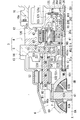
- FIG. 4 is an enlarged view of a power transmission device and its surroundings.
- FIG. 1 is a diagram illustrating a power transmission device 1 according to this embodiment.
- FIG. 2 is an enlarged view around the reduction mechanism 3 (the first planetary reduction gear 4, the second planetary reduction gear 5) of the power transmission device 1.
- the power transmission device 1 includes a motor 2, a reduction mechanism 3 (first planetary reduction gear 4, second planetary reduction gear 5) that reduces the output rotation of the motor 2 and inputs the reduced rotation to a differential device 6, and a drive shaft 8 ( 8A, 8B).
- a reduction mechanism 3 first planetary reduction gear 4, second planetary reduction gear 5 that reduces the output rotation of the motor 2 and inputs the reduced rotation to a differential device 6, and a drive shaft 8 ( 8A, 8B).
- the speed reduction mechanism 3 (first planetary reduction gear 4, second planetary reduction gear 5), the differential device 6, and the drive shaft 8 (8A, 8A, 8B) are provided.
- the output rotation of the motor 2 is decelerated by the reduction mechanism 3 and input to the differential device 6, and then via the drive shaft 8 (8A, 8B), the left and right drive wheels of the vehicle on which the power transmission device 1 is mounted.
- the drive shaft 8A is connected to the left wheel of the vehicle equipped with the power transmission device 1 so as to be able to rotate
- the drive shaft 8B is connected to the right wheel to be able to rotate.
- first planetary reduction gear 4 is connected downstream of the motor 2
- second planetary reduction gear 5 is connected downstream of the first planetary reduction gear 4.
- the differential device 6 is connected downstream of the second planetary reduction gear 5, and the drive shafts 8, 8 are connected downstream of the differential device 6.
- the motor 2 has a cylindrical motor shaft 20, a cylindrical rotor core 21 externally mounted on the motor shaft 20, and a stator core 25 surrounding the outer periphery of the rotor core 21 at predetermined intervals.
- the motor shaft 20 is provided so as to be relatively rotatable with respect to the drive shaft 8B in a state where the motor shaft 20 is externally attached to the drive shaft 8B.
- bearings B1 and B1 are externally inserted and fixed to the outer peripheries of the one end 20a side and the other end 20b side in the longitudinal direction.
- One end 20a side of the motor shaft 20 is rotatably supported by the cylindrical motor support portion 121 of the intermediate case 12 via the bearing B1.
- the other end 20b side of the motor shaft 20 is rotatably supported by a cylindrical motor support portion 111 of the cover 11 via a bearing B1.
- the motor 2 has a motor housing 10 that surrounds the outer periphery of the rotor core 21 at predetermined intervals.
- the intermediate case 12 is joined to one end 10a of the motor housing 10, and the cover 11 is joined to the other end 10b of the motor housing 10.
- Sealing rings S, S are provided at one end 10a and the other end 10b of the motor housing 10.
- One end 10a of the motor housing 10 is joined to the annular base 120 of the intermediate case 12 without a gap by a seal ring S provided on the one end 10a.
- the other end 10b of the motor housing 10 is joined to the annular joint portion 110 of the cover 11 without a gap by a seal ring S provided on the other end 10b.
- the base portion 120 and the motor support portion 121 are provided with their positions displaced in the rotation axis X direction.
- the motor support portion 121 is inserted inside the motor housing 10.
- the motor support portion 121 is arranged on the inner diameter side of the coil end 253a, which will be described later, and faces the one end portion 21a of the rotor core 21 with a gap in the rotation axis X direction (see FIG. 2).
- the connecting portion 123 (see FIG. 2) that connects the base portion 120 and the motor supporting portion 121 is provided so as to avoid contact between the coil end 253a and the side plate portion 452 described later.
- a bearing retainer 125 is fixed to the end surface 121a of the motor support 121 on the rotor core 21 side.
- the bearing retainer 125 has a ring shape when viewed from the rotation axis X direction.
- the inner diameter side of the bearing retainer 125 is in contact with the side surface of the outer race B1b of the bearing B1 supported by the motor support portion 121 from the rotation axis X direction.
- the bearing retainer 125 prevents the bearing B1 from falling off the motor support 121.
- the joint portion 110 and the motor support portion 111 are provided with their positions displaced in the direction of the rotation axis X.
- the motor support portion 111 is inserted inside the motor housing 10.
- the motor support portion 111 is arranged on the inner diameter side of a coil end 253b, which will be described later, and faces the other end portion 21b of the rotor core 21 with a gap in the rotation axis X direction.
- the connecting portion 115 that connects the joint portion 110 and the side wall portion 113 of the cover 11 is provided so as to avoid contact between the coil end 253b and the support cylinder 112 described later.
- the rotor core 21 is arranged between the motor support portion 111 on the cover 11 side and the motor support portion 121 on the intermediate case 12 side.
- the rotor core 21 is formed by laminating a plurality of silicon steel plates, and each of the silicon steel plates is externally attached to the motor shaft 20 in a state in which the relative rotation with the motor shaft 20 is restricted.
- the silicon steel plate When viewed from the direction of the rotation axis X of the motor shaft 20, the silicon steel plate has a ring shape.
- N and S pole magnets (not shown) alternate in the circumferential direction around the rotation axis X. It is provided in.
- the one end 21 a of the rotor core 21 in the direction of the rotation axis X is positioned by the large diameter portion 203 of the motor shaft 20.
- the other end 21b of the rotor core 21 is positioned by a stopper 23 press-fitted into the motor shaft 20.
- the stator core 25 is formed by laminating a plurality of electromagnetic steel plates, and each of the electromagnetic steel plates is a ring-shaped yoke portion 251 fixed to the inner periphery of the motor housing 10, and the rotor core from the inner periphery of the yoke portion 251.
- the tooth portion 252 protruding toward the 21 side is provided.
- the stator core 25 having a configuration in which the winding wire 253 is distributedly wound over a plurality of teeth portions 252 is adopted.
- the stator core 25 includes coil ends 253a and 253b protruding in the rotation axis X direction. The length in the rotation axis direction is longer than that of the rotor core 21.
- stator core in which windings are concentratedly wound may be adopted for each of the plurality of teeth portions protruding toward the rotor core 21 side.
- the bearing B1 is press-fitted to the outer periphery of the region on the one end 20a side of the large diameter portion 203.
- one side surface of the inner race B1a of the bearing B1 in the rotation axis X direction is in contact with a step portion 204 provided on the outer periphery of the motor shaft 20.
- a ring-shaped stopper 205 press-fitted to the outer periphery of the motor shaft 20 is in contact.
- the bearing B1 is positioned by the stopper 205 at a position where the inner race B1a is brought into contact with the step portion 204.
- the one end 20a of the motor shaft 20 is located closer to the differential device 6 side (left side in the figure) than the stopper 205.
- the one end 20a in the direction of the rotation axis X faces the side surface 41a of the sun gear 41 of the first planetary reduction gear 4 at a distance.
- the cylindrical wall 122 is located radially outside the motor shaft 20.
- the cylindrical wall 122 projects from the motor support 121 toward the differential device 6 side, and the tip 122a of the cylindrical wall 122 faces the side surface 41a of the sun gear 41 of the first planetary reduction gear 4 with a gap.
- the cylindrical wall 122 surrounds the outer periphery of the motor shaft 20 at a predetermined interval, and a lip seal RS is installed between the cylindrical wall 122 and the motor shaft 20.
- the lip seal RS is provided to partition a space Sa (see FIG. 1) on the inner diameter side of the motor housing 10 and a space Sb (see FIG. 1) on the inner diameter side of the intermediate case 12.
- the space Sb on the inner diameter side of the intermediate case 12 communicates with a space Sc in a case 13 that houses a differential gear 6 described later, and the lubricating oil of the differential gear 6 is sealed therein.
- the lip seal RS is provided to prevent the lubricating oil from flowing into the space Sa on the inner diameter side of the motor housing 10.
- the region 202 on the one end 20a side of the motor shaft 20 is formed with an inner diameter larger than the region 201 in which the rotor core 21 is externally inserted.
- the cylindrical coupling portion 411 of the sun gear 41 is inserted inside the region 202 on the side of the one end 20a. In this state, the region 202 on the one end 20a side of the motor shaft 20 and the connecting portion 411 of the sun gear 41 are spline-fitted so that they cannot rotate relative to each other.
- the output rotation of the motor 2 is input to the sun gear 41 of the first planetary reduction gear 4 via the motor shaft 20, and the sun gear 41 is rotated about the rotation axis X by the rotational driving force of the motor 2.
- the sun gear 41 has a connecting portion 411 extending from the side surface 41a on the inner diameter side in the rotation axis X direction.
- the connecting portion 411 is formed integrally with the sun gear 41, and a through hole 410 is formed across the inner diameter side of the sun gear 41 and the inner diameter side of the connecting portion 411.
- the sun gear 41 is rotatably supported on the outer periphery of the drive shaft 8B that penetrates the through hole 410.
- the ring gear 42 fixed to the inner circumference of the base 120 of the intermediate case 12 is located on the outer diameter side of the sun gear 41 in the radial direction of the rotation axis X.
- a pinion gear 43 rotatably supported by a pinion shaft 44 meshes with the outer circumference of the sun gear 41 and the inner circumference of the ring gear 42. ..
- the pinion gear 43 is rotatably supported on the outer circumference of the pinion shaft 44 via a needle bearing NB.
- the pinion shaft 44 penetrates the pinion gear 43 in the direction of the axis X1 along the rotation axis X.
- One end and the other end of the pinion shaft 44 in the longitudinal direction are supported by the pair of side plate portions 451 and 452 of the carrier 45.
- the side plate portions 451 and 452 are provided in parallel with each other with an interval in the rotation axis X direction.
- a plurality of pinion gears 43 (for example, four) are provided at predetermined intervals in the circumferential direction around the rotation axis X between the side plate portions 451 and 452.
- the side plate portion 451 located on the differential device 6 side is provided with a cylindrical connecting portion 453.
- the connecting portion 453 of the side plate portion 451 is arranged concentrically with respect to the rotation axis X, and projects along the rotation axis X in a direction approaching the differential device 6 (leftward in the drawing).
- a ring-shaped intermediate cover 14 is located on the differential device 6 side when viewed from the intermediate case 12.
- the intermediate cover 14 is provided so as to be sandwiched between the intermediate case 12 and the case 13.
- the connecting portion 453 provided on the inner diameter side of the side plate portion 451 penetrates the central opening 140 of the intermediate cover 14 from the motor 2 side to the left on the differential device 6 side.
- the tip 453 a of the connecting portion 453 is located inside the case 13 attached to the intermediate cover 14.
- the tip 453a of the connecting portion 453 in the direction of the rotation axis X faces the side surface 51a of the sun gear 51 of the second planetary reduction gear 5 with a gap.
- a cylindrical connecting portion 511 extending from the sun gear 51 is inserted and spline-fitted inside the connecting portion 453, and the connecting portion 453 on the first planetary reduction gear 4 side and the second planetary reduction gear 5 side are connected.
- the connecting portion 511 is connected so as not to rotate relative to it.
- the sun gear 51 has a connecting portion 511 extending from the inner diameter side surface 51a in the rotation axis X direction.
- the connecting portion 511 is formed integrally with the sun gear 51, and a through hole 510 is formed so as to extend across the inner diameter side of the sun gear 51 and the inner diameter side of the connecting portion 511.
- the sun gear 51 is rotatably supported on the outer periphery of the drive shaft 8B that penetrates the through hole 510.
- a side surface 51b of the sun gear 51 on the differential device 6 side faces a cylindrical support portion 601 of a differential case 60 described later with a gap in the rotation axis X direction between the side surface 51b and the support portion 601.
- the sun gear 51 meshes with the large-diameter gear portion 531 of the stepped pinion gear 53 on the extension of the connecting portion 542 on the side of the first planetary reduction gear 4 described above.
- the stepped pinion gear 53 has a large-diameter gear portion 531 that meshes with the sun gear 51, and a small-diameter gear portion 532 that has a smaller diameter than the large-diameter gear portion 531.
- the stepped pinion gear 53 is a gear component in which a large-diameter gear portion 531 and a small-diameter gear portion 532 are integrally provided with a large-diameter gear portion 531 and a small-diameter gear portion 532 aligned in the direction of the axis X2 parallel to the rotation axis X.
- the stepped pinion gear 53 has a through hole 530 that penetrates the inner diameter sides of the large diameter gear portion 531 and the small diameter gear portion 532 in the direction of the axis X2.
- the stepped pinion gear 53 is rotatably supported on the outer periphery of the pinion shaft 54 that penetrates the through hole 530 via a needle bearing NB.
- One end and the other end in the longitudinal direction of the pinion shaft 54 are supported by a side plate portion 651 integrally formed with the differential case 60 and side plate portions 551 arranged at intervals in the side plate portion.
- the side plate portions 651 and 551 are provided in parallel with each other with an interval in the rotation axis X direction.
- a plurality of stepped pinion gears 53 (for example, three) are provided at predetermined intervals in the circumferential direction around the rotation axis X between the side plate portions 651 and 551.
- Each of the small diameter gear parts 532 meshes with the inner circumference of the ring gear 52.
- the ring gear 52 is spline-fitted to the inner circumference of the case 13, and the ring gear 52 is restricted from rotating relative to the case 13.
- a cylindrical portion 552 that extends toward the first planetary reduction gear 4 side is provided on the inner diameter side of the side plate portion 551.
- the tubular portion 552 penetrates the center opening 140 of the intermediate cover 14 from the differential device 6 side to the motor 2 side (right side in the drawing).
- the tip end 552a of the tubular portion 552 faces the side plate portion 451 of the carrier 45 of the first planetary reduction gear 4 with a space in the direction of the rotation axis X.
- the tubular portion 552 is located radially outside the meshing portion of the connecting portion 453 on the first planetary reduction gear 4 side and the connecting portion 511 on the second planetary reduction gear 5 side.
- the bearing B2 fixed to the inner circumference of the opening 140 of the intermediate cover 14 is in contact with the outer circumference of the tubular portion 552.
- the tubular portion 552 of the side plate portion 551 is rotatably supported by the intermediate cover 14 via the bearing B2.
- one of the side plate portions 551 and the side plate portions 651 forming the carrier 55 is formed integrally with the differential case 60 of the differential device 6.
- the output rotation of the motor 2 reduced in speed by the first planetary reduction gear 4 is input to the sun gear 51.
- the output rotation input to the sun gear 51 is input to the stepped pinion gear 53 via the large-diameter gear portion 531 meshing with the sun gear 51, and the stepped pinion gear 53 rotates about the axis X2.
- the small-diameter gear portion 532 integrally formed with the large-diameter gear portion 531 rotates around the axis X2 integrally with the large-diameter gear portion 531.
- the small-diameter gear portion 532 meshes with the ring gear 52 fixed to the inner circumference of the case 13. Therefore, when the small diameter gear portion 532 rotates about the axis X2, the stepped pinion gear 53 rotates about the rotation axis X while rotating about the axis X2.
- the differential case 60 is linked with the circumferential displacement of the stepped pinion gear 53 around the rotation axis X. It rotates around the rotation axis X.
- the outer diameter R2 of the small diameter gear portion 532 is smaller than the outer diameter R1 of the large diameter gear portion 531 (see FIG. 2).
- the sun gear 51 serves as an output rotation input portion of the motor
- the carrier 55 that supports the stepped pinion gear 53 serves as an input rotation output portion.
- the rotation input to the sun gear 51 of the second planetary reduction gear 5 is greatly reduced by the stepped pinion gear 53, and then output to the differential case 60 in which the side plate portion 651 of the carrier 55 is integrally formed.
- the differential case 60 is formed in a hollow shape in which the shaft 61, the bevel gears 62A and 62B, and the side gears 63A and 63B are housed inside.
- tubular support parts 601 and 602 are provided on both sides in the direction of the rotation axis X (left and right direction in the drawing).
- the support portions 601 and 602 extend along the rotation axis X in the direction away from the shaft 61.
- the inner race B2a of the bearing B2 is press-fitted on the outer periphery of the support portion 602.
- the outer race B2b of the bearing B2 is held by the ring-shaped support portion 131 of the case 13, and the support portion 602 of the differential case 60 is rotatably supported by the case 13 via the bearing B2.
- the drive shaft 8A penetrating the opening 130 of the case 13 is inserted into the support portion 602 from the rotation axis X direction, and the drive shaft 8A is rotatably supported by the support portion 602.
- a lip seal RS is fixed to the inner circumference of the opening 130, and a lip portion (not shown) of the lip seal RS elastically contacts the outer circumference of the drive shaft 8A to open the outer circumference of the drive shaft 8A.
- the gap with the inner circumference of the portion 130 is sealed.
- the drive shaft 8B penetrating the opening 114 of the cover 11 is inserted into the support portion 601 from the rotation axis direction.
- the drive shaft 8B is provided across the inner diameter side of the motor shaft 20 of the motor 2, the sun gear 41 of the first planetary reduction gear 4, and the sun gear 51 of the second planetary reduction gear 5 in the rotation axis X direction.
- the tip side of the shaft 8B is rotatably supported by the support portion 601.
- a lip seal RS is fixed to the inner circumference of the opening 114 of the cover 11, and a lip portion (not shown) of the lip seal RS elastically contacts the outer circumference of the drive shaft 8B, so that the drive shaft 8B is covered.
- the gap between the outer circumference and the inner circumference of the opening 114 is sealed.
- side gears 63A and 63B are spline-fitted to the outer circumferences of the tip ends of the drive shafts 8A and 8B, and the side gears 63A and 63B and the drive shaft 8 (8A, 8B) rotate around the rotation axis X. Is integrally rotatably connected to.
- the differential case 60 is provided with shaft holes 60a and 60b penetrating in a direction orthogonal to the rotation axis X at positions symmetrical with respect to the rotation axis X.
- the shaft holes 60a and 60b are located on the axis line Y orthogonal to the rotation axis X, and the one end 61a side and the other end 61b side of the shaft 61 are inserted.
- the one end 61a side and the other end 61b side of the shaft 61 are fixed to the differential case 60 by a pin P, and the shaft 61 is prohibited from rotating around the axis Y.
- the lower side of the differential case 60 is immersed in the lubricating oil in the case 13.
- the lubricating oil in the case 13 is adjusted to a height at which the one end 61a or the other end 61b of the shaft 61 is located at least in the lubricating oil. Is stored.
- the shaft 61 is located between the side gears 63A and 63B in the differential case 60, and is arranged along the axis Y.
- Bevel gears 62A and 62B are externally inserted and rotatably supported on a shaft 61 in the differential case 60.
- Two bevel gears 62A and 62B are provided at intervals in the longitudinal direction of the shaft 61 (the axial direction of the axis Y), and the bevel gears 62A and 62B are arranged with their teeth facing each other. ing.
- the bevel gears 62A and 62B are provided such that the shaft centers of the bevel gears 62A and 62B coincide with the shaft center of the shaft 61.
- side gears 63A and 63B are located on both sides of the bevel gears 62A and 62B in the rotation axis X direction.
- the side gears 63A and 63B are provided with two teeth spaced apart from each other in the rotation axis X direction with the teeth thereof facing each other.
- the bevel gears 62A and 62B and the side gears 63A and 63B are provided with teeth of each other. It is assembled in a state where it is engaged.
- the speed reduction mechanism 3 first planetary reduction gear 4, second planetary reduction gear 5
- the differential device 6 the drive shaft 8 (8A, 8A, 8B) are provided.
- the sun gear 41 is an output rotation input section of the motor 2
- the carrier 45 supporting the pinion gear 43 is an input rotation output section.
- the pinion gear 43 meshed with the outer circumference of the sun gear 41 and the inner circumference of the ring gear 42 rotates about the axis X1.
- the ring gear 42 is spline-fitted to the inner circumference of the intermediate case 12 (fixed member), and its relative rotation with the intermediate case 12 is restricted. Therefore, the pinion gear 43 revolves around the rotation axis X while rotating around the axis X1.
- the carrier 45 side plate portions 451 and 452 supporting the pinion gear 43 rotates about the rotation axis X at a rotation speed lower than the output rotation of the motor 2.
- the connecting portion 453 of the carrier 45 is connected to the connecting portion 511 of the sun gear 51 on the second planetary reduction gear 5 side, and the rotation of the carrier 45 (the output rotation of the first planetary reduction gear 4) is It is input to the sun gear 51 of the 2 planetary reduction gear 5.
- the output portion (carrier 45) of the first planetary reduction gear 4 is connected to the input portion (sun gear 51) of the second planetary reduction gear 5 without using separate members such as a clutch and a speed change mechanism. That is, the output part (carrier 45) of the first planetary reduction gear 4 and the input part (sun gear 51) of the second planetary reduction gear 5 rotate integrally (always rotate together). Therefore, the distance between the first planetary reduction gear 4 and the second planetary reduction gear 5 can be reduced by the amount that another member is not on the power transmission path, which contributes to shortening in the axial direction.
- the sun gear 51 is an output rotation input portion of the second planetary reduction gear 5
- the carrier 55 that supports the stepped pinion gear 53 is an input rotation output portion. ing.
- the stepped pinion gear 53 (the large diameter gear portion 531 and the small diameter gear portion 532) is rotated about the axis X2 by the rotation input from the sun gear 51 side.
- the small diameter gear portion 532 of the stepped pinion gear 53 meshes with the ring gear 52 fixed to the inner circumference of the case 13. Therefore, the stepped pinion gear 53 rotates about the rotation axis X while rotating about the axis X2.
- the carrier 55 (side plate portions 551, 651) supporting the stepped pinion gear 53 rotates about the rotation axis X at a lower rotation speed than the rotation input from the first planetary reduction gear 4 side.
- the outer diameter R2 of the small diameter gear portion 532 is smaller than the outer diameter R1 of the large diameter gear portion 531 (see FIG. 2). Therefore, the rotation input to the sun gear 51 of the second planetary reduction gear 5 is reduced by the stepped pinion gear 53 to a greater extent than in the case of the first planetary reduction gear 4, and then the side plate portion 651 of the carrier 55 is integrated. Is output to the differential case 60 (differential device 6) formed on the.
- the rotation input to the differential case 60 is transmitted via the drive shaft 8 (8A, 8B) to the left and right drive wheels (not shown) of the vehicle in which the power transmission device 1 is mounted.
- the first planetary reduction gear 4 and the second planetary reduction gear 5 that form the reduction mechanism 3 are arranged in series, and one of the second planetary reduction gears 5 is The pinion gear is a stepped pinion gear 53.
- the reduction gear ratio in the reduction gear mechanism 3 can be made larger than in the case where the planetary reduction gears having a normal pinion gear (stepless pinion gear) are simply arranged in series. it can.
- the power transmission device 1 has the following configuration.
- the power transmission device 1 is Motor 2 and A first planetary reduction gear 4 connected downstream of the motor 2; A second planetary reduction gear 5 connected downstream of the first planetary reduction gear 4; A differential device 6 (differential gear) connected downstream of the second planetary reduction gear 5; A drive shaft 8 (8A, 8B) connected downstream of the differential device 6.
- the drive shaft 8B includes an inner diameter side of the rotor core 21 of the motor 2 (inner circumference of the rotor), an inner diameter side of the sun gear 41 of the first planetary reduction gear 4 (inner circumference), and an inner diameter of the sun gear 51 of the second planetary reduction gear 5. It is arranged so as to penetrate through the side (inner circumference).
- the pinion gear 43 (pinion) of the first planetary reduction gear 4 is a stepless pinion gear
- the pinion gear 53 of the second planetary reduction gear 5 is a stepped pinion gear.
- the uniaxial type power transmission device 1 in order to increase the reduction ratio of the output rotation of the motor 2, it is conceivable to add a planet reduction gear (planetary gear mechanism) on the transmission path of the output rotation of the motor 2. ..
- a planet reduction gear planetary gear mechanism
- there are two types of pinion gears of the planetary reduction gears a stepped type that easily increases the reduction ratio and a stepless type that easily reduces the size. If only the size of the reduction gear ratio is pursued, the pinions of all planetary reduction gears may be stepped types, but in that case, the power transmission device 1 becomes large in the radial direction. That is, the problem of increasing the size remains.
- the first planetary reduction gear 4 located downstream of the motor 2 and upstream of the second planetary reduction gear 5 is provided at a position sandwiched between the motor 2 and the second planetary reduction gear 5. Therefore, it is difficult to take a space around the first planetary reduction gear 4.
- the second planetary reduction gear 5 located downstream of the second planetary reduction gear 5 and upstream of the differential device 6 is located between the first planetary reduction gear 4 and the differential case 60 of the differential device 6. Since it is provided, it is easier to take a space in the periphery than the first planetary reduction gear 4.
- the reduction ratio can be increased while suppressing the size increase.
- the power transmission device 1 has the following configuration. (2) In the first planetary reduction gear 4, the sun gear 41 is an input element for output rotation of the motor 2, the carrier 45 is an output element for rotation output from the first planetary reduction gear 4, and the ring gear 42. Is a fixed element.
- the ring gear 42 which has an annular shape when viewed from the direction of the rotation axis X, is a member located on the outermost diameter side in the first planetary reduction gear 4, and is close to the inner circumference of the intermediate case 12 (base 120) that is the fixed side member. Will be placed.
- the ring gear 42 is used as the fixed element, it is only necessary to fix the ring gear 42 to a fixed member arranged around the ring gear 42.
- the ring gear 42 is not used as a fixed element, a space for installing components for inputting/outputting rotation with respect to the ring gear 42 is required around the ring gear 42, but the ring gear 42 is used as a fixed element. It doesn't need that space. That is, in the power transmission device 1, useless space around the ring gear can be reduced.
- the sun gear 41 is a member located closest to the inner diameter side in the first planetary reduction gear 4, and the motor shaft 20 that outputs the rotation of the rotor core 21 (rotor) of the motor 2 is located on the inner diameter side of the power transmission device 1. ing.
- the sun gear 41 of the first planetary reduction gear 4 as an input element, the output element of the motor 2 (motor shaft 20) and the input element on the side of the first planetary reduction gear 4 (sun gear 41) are arranged in the rotation axis X direction. You can get closer. As a result, it is possible to reduce the size of the uniaxial type power transmission device 1 in the rotation axis X direction.
- the power transmission device 1 has the following configuration. (3) In the second planetary reduction gear 5, the sun gear 51 is an input element for output rotation of the first planetary reduction gear 4, and the carrier 55 is an output element for rotation output from the second planetary reduction gear 5.
- the ring gear 52 is a fixed element.
- the ring gear 52 which has an annular shape when viewed from the direction of the rotation axis X, is a member located on the outermost diameter side in the second planetary reduction gear 5, and is arranged close to the inner circumference of the case 13 that is the fixed side member. ..
- the ring gear 52 only needs to be fixed to the fixed member arranged around the ring gear 52.
- the ring gear 52 is not used as a fixed element, a space around the ring gear 52 for installing a component for inputting/outputting rotation with respect to the ring gear 52 is required, but the ring gear 52 should be used as a fixed element. It doesn't need that space. That is, in the power transmission device 1, useless space around the ring gear can be reduced.
- the sun gear 51 of the second planetary reduction gear 5 is a member located closest to the inner diameter side in the second planetary reduction gear 5.
- an output element of the first planetary reduction gear 4 and an input element of the second planetary reduction gear 5 can be obtained. Can be approached in the direction of the rotation axis X. As a result, it is possible to reduce the size of the uniaxial type power transmission device 1 in the rotation axis X direction.
- the output element of the second planetary reduction gear 5 and the differential device 6 can be brought close to each other in the rotation axis X direction. .. This also makes it possible to reduce the size of the uniaxial type power transmission device 1 in the direction of the rotation axis X.
- the power transmission device 1 has the following configuration. (4)
- the carrier 45 of the first planetary reduction gear 4 overlaps the sun gear 41 of the first planetary reduction gear 4 in the rotation axis X-axis direction.
- the carrier 45 of the first planetary reduction gear 4 is supported by a portion that rotates integrally with the sun gear 41 of the first planetary reduction gear 4 via a thrust bearing (needle bearing NB).
- the thrust bearing (needle bearing NB) can be thinly formed in the rotation axis X direction. Therefore, the needle bearing NB is interposed between the carrier 45 (side plate portion 451) and the sun gear 41 side (side surface 41b), and the carrier side and the sun gear side are supported via the needle bearing NB. Then, the carrier 45 (side plate portion 451) and the sun gear 41 side (side surface 41b) can be brought close to each other as much as possible, and the dimension in the axial direction of the single-shaft type power transmission device having two planetary reduction gears can be set. It is possible to reduce the size.
- downstream connection in the present specification means that power is transmitted from a component arranged upstream to a component arranged downstream.
- first planetary reduction gear 4 connected downstream of the motor 2
- direct connection in the present specification means that members are connected to each other so that power can be transmitted without using another member such as a speed reducing mechanism, a speed increasing mechanism, or a speed change mechanism that changes a speed reduction ratio.
Landscapes
- Engineering & Computer Science (AREA)
- Mechanical Engineering (AREA)
- General Engineering & Computer Science (AREA)
- Power Engineering (AREA)
- Chemical & Material Sciences (AREA)
- Combustion & Propulsion (AREA)
- Transportation (AREA)
- Retarders (AREA)
- Connection Of Motors, Electrical Generators, Mechanical Devices, And The Like (AREA)
Abstract
動力伝達装置(1)は、モータ(2)と、モータ(2)の下流に接続された第1遊星減速ギア(4)と、第1遊星減速ギア(4)の下流に接続された第2遊星減速ギア(5)と、第2遊星減速ギア(5)の下流に接続された差動装置(6)と、デファレンシャルギアの下流に接続されたドライブシャフト(8A、8B)と、を有する。ドライブシャフト(8B)は、モータ(2)のロータコア(21)の内径側と、第1遊星減速ギア(4)のサンギア(41)の内径側(内周)と、第2遊星減速ギア(5)のサンギア(51)の内径側と、を貫通して配置されている。第1遊星減速ギア(4)のピニオンギア(43)は、段無しピニオンギアであり、且つ、第2遊星減速ギア(5)のピニオンギア(53)は段付きピニオンである。
Description
本発明は、動力伝達装置に関する。
特許文献1から特許文献3には、動力伝達装置が開示されている。
特許文献1の動力伝達装置は、回転伝達に関与する3つの回転軸が並列に並んでおり、縦方向(重力方向)にサイズアップしやすい(以下、3軸タイプと呼ぶこととする)。
特許文献2の動力伝達装置は、モータのロータが中空軸となっており、この中空軸の内部をドライブシャフトが貫通している。そのため、3軸タイプと比較して縦方向のサイズダウンが可能となるが、大きなカウンタギアを配置しているため、縦方向にサイズアップしてしまう(以下、2軸タイプと呼ぶこととする)。
特許文献3の動力伝達装置は、カウンタギアではなく、段付きピニオンを有する遊星減速ギアを用いており、2軸タイプと比較して縦方向のサイズダウンが可能となる(以下、1軸タイプと呼ぶこととする)。
1軸タイプの動力伝達装置において、サイズアップを抑制しつつ減速比を大きくすることを求められている。
本発明は、
モータと、
前記モータの下流に接続された第1遊星減速ギアと、
前記第1遊星減速ギアの下流に接続された第2遊星減速ギアと、
前記第2遊星減速ギアの下流に接続されたデファレンシャルギアと、
前記デファレンシャルギアの下流に接続されたドライブシャフトと、を有し、
前記ドライブシャフトは、前記モータのロータの内周と、前記第1遊星減速ギアのサンギアの内周と、前記第2遊星減速ギアのサンギアの内周と、を貫通して配置されており、
前記第1遊星減速ギアのピニオンは段無しピニオンであり、且つ、前記第2遊星減速ギアのピニオンは段付きピニオンである構成の動力伝達装置とした。
モータと、
前記モータの下流に接続された第1遊星減速ギアと、
前記第1遊星減速ギアの下流に接続された第2遊星減速ギアと、
前記第2遊星減速ギアの下流に接続されたデファレンシャルギアと、
前記デファレンシャルギアの下流に接続されたドライブシャフトと、を有し、
前記ドライブシャフトは、前記モータのロータの内周と、前記第1遊星減速ギアのサンギアの内周と、前記第2遊星減速ギアのサンギアの内周と、を貫通して配置されており、
前記第1遊星減速ギアのピニオンは段無しピニオンであり、且つ、前記第2遊星減速ギアのピニオンは段付きピニオンである構成の動力伝達装置とした。
本発明によれば、サイズアップを抑制しつつ減速比を大きくすることができる。
以下、本発明の実施形態を説明する。
図1は、本実施形態にかかる動力伝達装置1を説明する図である。
図2は、動力伝達装置1の減速機構3(第1遊星減速ギア4、第2遊星減速ギア5)周りの拡大図である。
図1は、本実施形態にかかる動力伝達装置1を説明する図である。
図2は、動力伝達装置1の減速機構3(第1遊星減速ギア4、第2遊星減速ギア5)周りの拡大図である。
動力伝達装置1は、モータ2と、モータ2の出力回転を減速して差動装置6に入力する減速機構3(第1遊星減速ギア4、第2遊星減速ギア5)と、ドライブシャフト8(8A、8B)と、を有している。
動力伝達装置1では、モータ2の出力回転の伝達経路に沿って、減速機構3(第1遊星減速ギア4、第2遊星減速ギア5)と、差動装置6と、ドライブシャフト8(8A、8B)と、が設けられている。
モータ2の出力回転は、減速機構3で減速されて差動装置6に入力された後、ドライブシャフト8(8A、8B)を介して、動力伝達装置1が搭載された車両の左右の駆動輪(図示せず)に伝達される。図1では、ドライブシャフト8Aが、動力伝達装置1を搭載した車両の左輪に回転伝達可能に接続されていると共に、ドライブシャフト8Bが、右輪に回転伝達可能に接続されている。
モータ2の出力回転は、減速機構3で減速されて差動装置6に入力された後、ドライブシャフト8(8A、8B)を介して、動力伝達装置1が搭載された車両の左右の駆動輪(図示せず)に伝達される。図1では、ドライブシャフト8Aが、動力伝達装置1を搭載した車両の左輪に回転伝達可能に接続されていると共に、ドライブシャフト8Bが、右輪に回転伝達可能に接続されている。
ここで、第1遊星減速ギア4は、モータ2の下流に接続されており、第2遊星減速ギア5は、第1遊星減速ギア4の下流に接続されている。差動装置6は、第2遊星減速ギア5の下流に接続されており、ドライブシャフト8、8は、差動装置6の下流に接続されている。
モータ2は、円筒状のモータシャフト20と、モータシャフト20に外挿された円筒状のロータコア21と、ロータコア21の外周を所定間隔で囲むステータコア25とを、有している。
モータシャフト20は、ドライブシャフト8Bに外挿された状態で、ドライブシャフト8Bに対して相対回転可能に設けられている。
モータシャフト20では、長手方向の一端20a側と他端20b側の外周に、ベアリングB1、B1が外挿されて固定されている。
モータシャフト20の一端20a側は、ベアリングB1を介して、中間ケース12の円筒状のモータ支持部121で回転可能に支持されている。
モータシャフト20の他端20b側は、ベアリングB1を介して、カバー11の円筒状のモータ支持部111で回転可能に支持されている。
モータシャフト20では、長手方向の一端20a側と他端20b側の外周に、ベアリングB1、B1が外挿されて固定されている。
モータシャフト20の一端20a側は、ベアリングB1を介して、中間ケース12の円筒状のモータ支持部121で回転可能に支持されている。
モータシャフト20の他端20b側は、ベアリングB1を介して、カバー11の円筒状のモータ支持部111で回転可能に支持されている。
モータ2は、ロータコア21の外周を所定間隔で囲むモータハウジング10を有している。本実施形態では、モータハウジング10の一端10aに、中間ケース12が接合されており、モータハウジング10の他端10bに、カバー11が接合されている。
モータハウジング10の一端10aと他端10bには、シールリングS、Sが設けられている。モータハウジング10の一端10aは、当該一端10aに設けたシールリングSにより、中間ケース12の環状の基部120に隙間なく接合されている。
モータハウジング10の他端10bは、当該他端10bに設けたシールリングSにより、カバー11の環状の接合部110に隙間なく接合されている。
モータハウジング10の他端10bは、当該他端10bに設けたシールリングSにより、カバー11の環状の接合部110に隙間なく接合されている。
中間ケース12では、基部120とモータ支持部121とが、回転軸X方向で位置をずらして設けられている。
本実施形態では、中間ケース12をモータハウジング10の一端10aに固定すると、モータ支持部121が、モータハウジング10の内側に挿入されるようになっている。
本実施形態では、中間ケース12をモータハウジング10の一端10aに固定すると、モータ支持部121が、モータハウジング10の内側に挿入されるようになっている。
この状態においてモータ支持部121は、後記するコイルエンド253aの内径側で、ロータコア21の一端部21aに、回転軸X方向の隙間をあけて対向して配置される(図2参照)。
そして、基部120とモータ支持部121とを接続する接続部123(図2参照)は、コイルエンド253aと後記する側板部452との接触を避けて設けられている。
そして、基部120とモータ支持部121とを接続する接続部123(図2参照)は、コイルエンド253aと後記する側板部452との接触を避けて設けられている。
なお、モータ支持部121のロータコア21側の端面121aには、ベアリングリテーナ125が固定されている。
ベアリングリテーナ125は、回転軸X方向から見てリング状を成している。ベアリングリテーナ125の内径側は、モータ支持部121で支持されたベアリングB1のアウタレースB1bの側面に回転軸X方向から当接している。ベアリングリテーナ125は、モータ支持部121からのベアリングB1の脱落を阻止している。
ベアリングリテーナ125は、回転軸X方向から見てリング状を成している。ベアリングリテーナ125の内径側は、モータ支持部121で支持されたベアリングB1のアウタレースB1bの側面に回転軸X方向から当接している。ベアリングリテーナ125は、モータ支持部121からのベアリングB1の脱落を阻止している。
図1に示すように、カバー11では、接合部110とモータ支持部111とが、回転軸X方向で位置をずらして設けられている。
本実施形態では、カバー11の接合部110をモータハウジング10の他端10bに固定すると、モータ支持部111が、モータハウジング10の内側に挿入されるようになっている。
本実施形態では、カバー11の接合部110をモータハウジング10の他端10bに固定すると、モータ支持部111が、モータハウジング10の内側に挿入されるようになっている。
この状態においてモータ支持部111は、後記するコイルエンド253bの内径側で、ロータコア21の他端部21bに、回転軸X方向の隙間をあけて対向して配置される。
そして、接合部110と、カバー11の側壁部113とを接続する接続部115は、コイルエンド253bと後記する支持筒112との接触を避けて設けられている。
そして、接合部110と、カバー11の側壁部113とを接続する接続部115は、コイルエンド253bと後記する支持筒112との接触を避けて設けられている。
モータハウジング10の内側では、カバー11側のモータ支持部111と、中間ケース12側のモータ支持部121との間に、ロータコア21が配置されている。
ロータコア21は、複数の珪素鋼板を積層して形成したものであり、珪素鋼板の各々は、モータシャフト20との相対回転が規制された状態で、モータシャフト20に外挿されている。
モータシャフト20の回転軸X方向から見て、珪素鋼板はリング状を成しており、珪素鋼板の外周側では、図示しないN極とS極の磁石が、回転軸X周りの周方向に交互に設けられている。
モータシャフト20の回転軸X方向から見て、珪素鋼板はリング状を成しており、珪素鋼板の外周側では、図示しないN極とS極の磁石が、回転軸X周りの周方向に交互に設けられている。
回転軸X方向におけるロータコア21の一端部21aは、モータシャフト20の大径部203で位置決めされている。ロータコア21の他端部21bは、モータシャフト20に圧入されたストッパ23で位置決めされている。
ステータコア25は、複数の電磁鋼板を積層して形成したものであり、電磁鋼板の各々は、モータハウジング10の内周に固定されたリング状のヨーク部251と、ヨーク部251の内周からロータコア21側に突出するティース部252を、有している。
本実施形態では、巻線253を、複数のティース部252に跨がって分布巻きした構成のステータコア25を採用しており、ステータコア25は、回転軸X方向に突出するコイルエンド253a、253bの分だけ、ロータコア21よりも回転軸方向の長さが長くなっている。
本実施形態では、巻線253を、複数のティース部252に跨がって分布巻きした構成のステータコア25を採用しており、ステータコア25は、回転軸X方向に突出するコイルエンド253a、253bの分だけ、ロータコア21よりも回転軸方向の長さが長くなっている。
なお、ロータコア21側に突出する複数のティース部の各々に、巻線を集中巻きした構成のステータコアを採用しても良い。
モータシャフト20では、大径部203よりも一端20a側の領域の外周に、ベアリングB1が圧入されている。
図2に示すように、ベアリングB1のインナレースB1aは、回転軸X方向の一方の側面が、モータシャフト20の外周に設けた段部204に当接している。インナレースB1aは、他方の側面に、モータシャフト20の外周に圧入されたリング状のストッパ205が当接している。
ストッパ205によりベアリングB1は、インナレースB1aを、段部204に当接させた位置で位置決めされている。
図2に示すように、ベアリングB1のインナレースB1aは、回転軸X方向の一方の側面が、モータシャフト20の外周に設けた段部204に当接している。インナレースB1aは、他方の側面に、モータシャフト20の外周に圧入されたリング状のストッパ205が当接している。
ストッパ205によりベアリングB1は、インナレースB1aを、段部204に当接させた位置で位置決めされている。
モータシャフト20の一端20aは、ストッパ205よりも差動装置6側(図中、左側)に位置している。回転軸X方向において一端20aは、第1遊星減速ギア4のサンギア41の側面41aに、間隔をあけて対向している。
モータシャフト20の一端20a側では、モータシャフト20の径方向外側に、円筒壁122が位置している。
円筒壁122は、モータ支持部121から差動装置6側に突出しており、円筒壁122の先端122aは、第1遊星減速ギア4のサンギア41の側面41aに間隔をあけて対向している。
円筒壁122は、モータ支持部121から差動装置6側に突出しており、円筒壁122の先端122aは、第1遊星減速ギア4のサンギア41の側面41aに間隔をあけて対向している。
円筒壁122は、モータシャフト20の外周を所定間隔で囲んでおり、円筒壁122とモータシャフト20との間には、リップシールRSが設置されている。
リップシールRSは、モータハウジング10の内径側の空間Sa(図1参照)と、中間ケース12の内径側の空間Sb(図1参照)とを、区画するために設けられている。
リップシールRSは、モータハウジング10の内径側の空間Sa(図1参照)と、中間ケース12の内径側の空間Sb(図1参照)とを、区画するために設けられている。
中間ケース12の内径側の空間Sbは、後記する差動装置6を収容するケース13内の空間Scと連絡しており、差動装置6の潤滑油が封入されている。リップシールRSは、モータハウジング10の内径側の空間Saへの潤滑油の流入を阻止するために設けられている。
図2に示すように、モータシャフト20の一端20a側の領域202は、ロータコア21が外挿された領域201よりも大きい内径で形成されている。
この一端20a側の領域202の内側には、サンギア41の円筒状の連結部411が挿入されている。この状態において、モータシャフト20の一端20a側の領域202と、サンギア41の連結部411とが、相対回転不能にスプライン嵌合している。
この一端20a側の領域202の内側には、サンギア41の円筒状の連結部411が挿入されている。この状態において、モータシャフト20の一端20a側の領域202と、サンギア41の連結部411とが、相対回転不能にスプライン嵌合している。
そのため、モータ2の出力回転が、モータシャフト20を介して、第1遊星減速ギア4のサンギア41に入力されて、サンギア41がモータ2の回転駆動力で、回転軸X回りに回転する。
サンギア41は、内径側の側面41aから回転軸X方向に延びる連結部411を有している。連結部411は、サンギア41と一体に形成されおり、サンギア41の内径側と連結部411の内径側とに跨がって、貫通孔410が形成されている。
サンギア41は、貫通孔410を貫通したドライブシャフト8Bの外周で回転可能に支持されている。
サンギア41は、貫通孔410を貫通したドライブシャフト8Bの外周で回転可能に支持されている。
回転軸Xの径方向におけるサンギア41の外径側には、中間ケース12の基部120の内周に固定されたリングギア42が位置している。回転軸Xの径方向において、サンギア41とリングギア42の間では、ピニオン軸44で回転可能に支持されたピニオンギア43が、サンギア41の外周と、リングギア42の内周に噛合している。
ピニオンギア43は、ニードルベアリングNBを介して、ピニオン軸44の外周で回転可能に支持されている。ピニオン軸44は、ピニオンギア43を回転軸Xに沿う軸線X1方向に貫通している。ピニオン軸44の長手方向の一端と他端は、キャリア45の一対の側板部451、452で支持されている。
側板部451、452は、回転軸X方向に間隔をあけて互いに平行に設けられている。
側板部451、452の間では、複数のピニオンギア43が回転軸X周りの周方向に所定間隔で複数(例えば、4つ)設けられている。
側板部451、452の間では、複数のピニオンギア43が回転軸X周りの周方向に所定間隔で複数(例えば、4つ)設けられている。
差動装置6側に位置する側板部451には、円筒状の連結部453が設けられている。
側板部451において連結部453は、回転軸Xに対して同心に配置されていると共に、回転軸Xに沿って、差動装置6に近づく方向(図中、左方向)に突出している。
側板部451において連結部453は、回転軸Xに対して同心に配置されていると共に、回転軸Xに沿って、差動装置6に近づく方向(図中、左方向)に突出している。
中間ケース12から見て差動装置6側には、リング状の中間カバー14が位置している。中間カバー14は、中間ケース12とケース13との間に挟み込まれた状態で設けられている。
側板部451の内径側に設けられた連結部453は、中間カバー14の中央の開口140を、モータ2側から差動装置6側の左方に貫通している。
連結部453の先端453aは、中間カバー14に取り付けられたケース13内に位置している。回転軸X方向において連結部453の先端453aは、第2遊星減速ギア5のサンギア51の側面51aに、間隔をあけて対向している。
側板部451の内径側に設けられた連結部453は、中間カバー14の中央の開口140を、モータ2側から差動装置6側の左方に貫通している。
連結部453の先端453aは、中間カバー14に取り付けられたケース13内に位置している。回転軸X方向において連結部453の先端453aは、第2遊星減速ギア5のサンギア51の側面51aに、間隔をあけて対向している。
連結部453の内側には、サンギア51から延びる円筒状の連結部511が挿入されてスプライン嵌合しており、第1遊星減速ギア4側の連結部453と、第2遊星減速ギア5側の連結部511とが、相対回転不能に連結されている。
サンギア51は、内径側の側面51aから回転軸X方向に延びる連結部511を有している。連結部511は、サンギア51と一体に形成されおり、サンギア51の内径側と連結部511の内径側とに跨がって、貫通孔510が形成されている。
サンギア51は、貫通孔510を貫通したドライブシャフト8Bの外周で回転可能に支持されている。
サンギア51は、貫通孔510を貫通したドライブシャフト8Bの外周で回転可能に支持されている。
サンギア51の差動装置6側の側面51bは、後記するデフケース60の筒状の支持部601に、回転軸X方向の隙間をあけて対向しており、側面51bと支持部601との間には、ニードルベアリングNBが介在している。
サンギア51は、前記した第1遊星減速ギア4側の連結部542の延長上で、段付きピニオンギア53の大径歯車部531に噛合している。
段付きピニオンギア53は、サンギア51に噛合する大径歯車部531と、大径歯車部531よりも小径の小径歯車部532とを有している。
段付きピニオンギア53は、大径歯車部531と小径歯車部532が、回転軸Xに平行な軸線X2方向で並んで、一体に設けられたギア部品である。
段付きピニオンギア53は、大径歯車部531と小径歯車部532が、回転軸Xに平行な軸線X2方向で並んで、一体に設けられたギア部品である。
段付きピニオンギア53は、大径歯車部531と小径歯車部532の内径側を軸線X2方向に貫通した貫通孔530を有している。
段付きピニオンギア53は、貫通孔530を貫通したピニオンシャフト54の外周で、ニードルベアリングNBを介して回転可能に支持されている。
ピニオンシャフト54の長手方向の一端と他端は、デフケース60と一体に形成された側板部651と、この側板部に間隔をあけて配置された側板部551で支持されている。
段付きピニオンギア53は、貫通孔530を貫通したピニオンシャフト54の外周で、ニードルベアリングNBを介して回転可能に支持されている。
ピニオンシャフト54の長手方向の一端と他端は、デフケース60と一体に形成された側板部651と、この側板部に間隔をあけて配置された側板部551で支持されている。
側板部651、551は、回転軸X方向に間隔をあけて互いに平行に設けられている。
側板部651、551の間では、複数の段付きピニオンギア53が回転軸X周りの周方向に所定間隔で複数(例えば、3つ)設けられている。
側板部651、551の間では、複数の段付きピニオンギア53が回転軸X周りの周方向に所定間隔で複数(例えば、3つ)設けられている。
小径歯車部532の各々は、リングギア52の内周に噛合している。リングギア52は、ケース13の内周にスプライン嵌合しており、リングギア52は、ケース13との相対回転が規制されている。
側板部551の内径側には、第1遊星減速ギア4側に延びる筒状部552が設けられている。筒状部552は、中間カバー14の中央の開口140を、差動装置6側からモータ2側(図中、右側)に貫通している。回転軸X方向において筒状部552の先端552aは、第1遊星減速ギア4のキャリア45の側板部451に、間隔をあけて対向している。
筒状部552は、第1遊星減速ギア4側の連結部453と、第2遊星減速ギア5側の連結部511との噛み合い部分の径方向外側に位置している。筒状部552の外周には、中間カバー14の開口140の内周に固定されたベアリングB2が接触している。側板部551の筒状部552は、ベアリングB2を介して、中間カバー14で回転可能に支持されている。
第2遊星減速ギア5では、キャリア55を構成する側板部551と側板部651のうちの一方の側板部651は、差動装置6のデフケース60と一体に形成されている。
第2遊星減速ギア5では、第1遊星減速ギア4で減速されたモータ2の出力回転が、サンギア51に入力される。
サンギア51に入力された出力回転は、サンギア51に噛合する大径歯車部531を介して、段付きピニオンギア53に入力されて、段付きピニオンギア53が軸線X2回りに回転する。
サンギア51に入力された出力回転は、サンギア51に噛合する大径歯車部531を介して、段付きピニオンギア53に入力されて、段付きピニオンギア53が軸線X2回りに回転する。
そうすると、大径歯車部531と一体に形成された小径歯車部532は、大径歯車部531と一体に軸線X2周りに回転する。
ここで、小径歯車部532は、ケース13の内周に固定されたリングギア52に噛合している。そのため、小径歯車部532が軸線X2回りに回転すると、段付きピニオンギア53は、軸線X2回りに自転しながら、回転軸X回りに回転する。
ここで、小径歯車部532は、ケース13の内周に固定されたリングギア52に噛合している。そのため、小径歯車部532が軸線X2回りに回転すると、段付きピニオンギア53は、軸線X2回りに自転しながら、回転軸X回りに回転する。
そうすると、ピニオンシャフト54の一端が、デフケース60と一体に形成された側板部651に支持されているので、段付きピニオンギア53の回転軸X周りの周方向の変位に連動して、デフケース60が回転軸X回りに回転する。
ここで、段付きピニオンギア53では、小径歯車部532の外径R2が大径歯車部531の外径R1よりも小さくなっている(図2参照)。
そして、第2遊星減速ギア5では、サンギア51が、モータの出力回転の入力部となっており、段付きピニオンギア53を支持するキャリア55が、入力された回転の出力部となっている。
そうすると、第2遊星減速ギア5のサンギア51に入力された回転は、段付きピニオンギア53により大きく減速されたのちに、キャリア55の側板部651が一体に形成されたデフケース60に出力される。
そして、第2遊星減速ギア5では、サンギア51が、モータの出力回転の入力部となっており、段付きピニオンギア53を支持するキャリア55が、入力された回転の出力部となっている。
そうすると、第2遊星減速ギア5のサンギア51に入力された回転は、段付きピニオンギア53により大きく減速されたのちに、キャリア55の側板部651が一体に形成されたデフケース60に出力される。
図1に示すように、デフケース60は、シャフト61と、かさ歯車62A、62Bと、サイドギア63A、63Bとを、内部に収納する中空状に形成されている。
デフケース60では、回転軸X方向(図中、左右方向)の両側部に、筒状の支持部601、602が設けられている。支持部601、602は、シャフト61から離れる方向に、回転軸Xに沿って延出している。
デフケース60では、回転軸X方向(図中、左右方向)の両側部に、筒状の支持部601、602が設けられている。支持部601、602は、シャフト61から離れる方向に、回転軸Xに沿って延出している。
支持部602の外周には、ベアリングB2のインナレースB2aが圧入されている。ベアリングB2のアウタレースB2bは、ケース13のリング状の支持部131で保持されており、デフケース60の支持部602は、ベアリングB2を介して、ケース13で回転可能に支持されている。
支持部602には、ケース13の開口部130を貫通したドライブシャフト8Aが、回転軸X方向から挿入されており、ドライブシャフト8Aは、支持部602で回転可能に支持されている。
開口部130の内周には、リップシールRSが固定されており、リップシールRSの図示しないリップ部が、ドライブシャフト8Aの外周に弾発的に接触することで、ドライブシャフト8Aの外周と開口部130の内周との隙間が封止されている。
開口部130の内周には、リップシールRSが固定されており、リップシールRSの図示しないリップ部が、ドライブシャフト8Aの外周に弾発的に接触することで、ドライブシャフト8Aの外周と開口部130の内周との隙間が封止されている。
支持部601には、カバー11の開口部114を貫通したドライブシャフト8Bが、回転軸方向から挿入されている。
ドライブシャフト8Bは、モータ2のモータシャフト20と、第1遊星減速ギア4のサンギア41と、第2遊星減速ギア5のサンギア51の内径側を回転軸X方向に横切って設けられており、ドライブシャフト8Bの先端側が、支持部601で回転可能に支持されている。
ドライブシャフト8Bは、モータ2のモータシャフト20と、第1遊星減速ギア4のサンギア41と、第2遊星減速ギア5のサンギア51の内径側を回転軸X方向に横切って設けられており、ドライブシャフト8Bの先端側が、支持部601で回転可能に支持されている。
カバー11の開口部114の内周には、リップシールRSが固定されており、リップシールRSの図示しないリップ部が、ドライブシャフト8Bの外周に弾発的に接触することで、ドライブシャフト8Bの外周と開口部114の内周との隙間が封止されている。
デフケース60の内部では、ドライブシャフト8A、8Bの先端部の外周に、サイドギア63A、63Bがスプライン嵌合しており、サイドギア63A、63Bとドライブシャフト8(8A、8B)とが、回転軸X周りに一体回転可能に連結されている。
デフケース60には、回転軸Xに直交する方向に貫通した軸孔60a、60bが、回転軸Xを挟んで対称となる位置に設けられている。
軸孔60a、60bは、回転軸Xに直交する軸線Y上に位置しており、シャフト61の一端61a側および他端61b側が挿入されている。
軸孔60a、60bは、回転軸Xに直交する軸線Y上に位置しており、シャフト61の一端61a側および他端61b側が挿入されている。
シャフト61の一端61a側および他端61b側は、ピンPでデフケース60に固定されており、シャフト61は、軸線Y周りの自転が禁止されている。
デフケース60の下部側は、ケース13内の潤滑油に浸っている。
実施の形態では、シャフト61の一端61aまたは他端61bが最も下部側に位置した際に、シャフト61の一端61aまたは他端61bが少なくとも潤滑油内に位置する高さまで、ケース13内に潤滑油が貯留されている。
デフケース60の下部側は、ケース13内の潤滑油に浸っている。
実施の形態では、シャフト61の一端61aまたは他端61bが最も下部側に位置した際に、シャフト61の一端61aまたは他端61bが少なくとも潤滑油内に位置する高さまで、ケース13内に潤滑油が貯留されている。
シャフト61は、デフケース60内において、サイドギア63A、63Bの間に位置しており、軸線Yに沿って配置されている。
デフケース60内においてシャフト61には、かさ歯車62A、62Bが外挿して回転可能に支持されている。
かさ歯車62A、62Bは、シャフト61の長手方向(軸線Yの軸方向)で間隔を空けて2つ設けられており、かさ歯車62A、62Bは、互いの歯部を対向させた状態で配置されている。シャフト61においてかさ歯車62A、62Bは、当該かさ歯車62A、62Bの軸心を、シャフト61の軸心と一致させて設けられている。
かさ歯車62A、62Bは、シャフト61の長手方向(軸線Yの軸方向)で間隔を空けて2つ設けられており、かさ歯車62A、62Bは、互いの歯部を対向させた状態で配置されている。シャフト61においてかさ歯車62A、62Bは、当該かさ歯車62A、62Bの軸心を、シャフト61の軸心と一致させて設けられている。
デフケース60内において、回転軸X方向におけるかさ歯車62A、62Bの両側には、サイドギア63A、63Bが位置している。
サイドギア63A、63Bは、互いの歯部を対向させた状態で、回転軸X方向に間隔を空けて2つ設けられており、かさ歯車62A、62Bとサイドギア63A、63Bとは、互いの歯部を噛合させた状態で組み付けられている。
サイドギア63A、63Bは、互いの歯部を対向させた状態で、回転軸X方向に間隔を空けて2つ設けられており、かさ歯車62A、62Bとサイドギア63A、63Bとは、互いの歯部を噛合させた状態で組み付けられている。
かかる構成の動力伝達装置1の作用を説明する。
動力伝達装置1では、モータ2の出力回転の伝達経路に沿って、減速機構3(第1遊星減速ギア4、第2遊星減速ギア5)と、差動装置6と、ドライブシャフト8(8A、8B)と、が設けられている。
動力伝達装置1では、モータ2の出力回転の伝達経路に沿って、減速機構3(第1遊星減速ギア4、第2遊星減速ギア5)と、差動装置6と、ドライブシャフト8(8A、8B)と、が設けられている。
モータ2の駆動により、ロータコア21が回転軸X回りに回転すると、ロータコア21と一体に回転するモータシャフト20を介して、第1遊星減速ギア4のサンギア41に回転が入力される。
図2に示すように、第1遊星減速ギア4では、サンギア41が、モータ2の出力回転の入力部、ピニオンギア43を支持するキャリア45が、入力された回転の出力部となっている。
サンギア41がモータ2の出力回転で回転軸X回りに回転すると、サンギア41の外周とリングギア42の内周に噛合したピニオンギア43が、軸線X1回りに回転する。
ここで、リングギア42は、中間ケース12(固定側部材)の内周にスプライン嵌合しており、中間ケース12との相対回転が規制されている。
そのため、ピニオンギア43は、軸線X1回りに回転しながら、回転軸X周りに公転する。これにより、ピニオンギア43を支持するキャリア45(側板部451、452)が、モータ2の出力回転よりも低い回転速度で回転軸X回りに回転する。
ここで、リングギア42は、中間ケース12(固定側部材)の内周にスプライン嵌合しており、中間ケース12との相対回転が規制されている。
そのため、ピニオンギア43は、軸線X1回りに回転しながら、回転軸X周りに公転する。これにより、ピニオンギア43を支持するキャリア45(側板部451、452)が、モータ2の出力回転よりも低い回転速度で回転軸X回りに回転する。
前記したようにキャリア45の連結部453は、第2遊星減速ギア5側のサンギア51の連結部511に連結されており、キャリア45の回転(第1遊星減速ギア4の出力回転)は、第2遊星減速ギア5のサンギア51に入力される。
なお、第1遊星減速ギア4の出力部(キャリア45)が、第2遊星減速ギア5の入力部(サンギア51)とクラッチ、変速機構等の別部材を介さずに連結されている。
即ち、第1遊星減速ギア4の出力部(キャリア45)と、第2遊星減速ギア5の入力部(サンギア51)は、一体回転する(常時、一体回転する)。
よって、別部材が動力伝達経路上にない分だけ、第1遊星減速ギア4と第2遊星減速ギア5の距離を近づけることができるので軸方向の短縮に寄与する。
なお、第1遊星減速ギア4の出力部(キャリア45)が、第2遊星減速ギア5の入力部(サンギア51)とクラッチ、変速機構等の別部材を介さずに連結されている。
即ち、第1遊星減速ギア4の出力部(キャリア45)と、第2遊星減速ギア5の入力部(サンギア51)は、一体回転する(常時、一体回転する)。
よって、別部材が動力伝達経路上にない分だけ、第1遊星減速ギア4と第2遊星減速ギア5の距離を近づけることができるので軸方向の短縮に寄与する。
第2遊星減速ギア5では、サンギア51が、第2遊星減速ギア5の出力回転の入力部となっており、段付きピニオンギア53を支持するキャリア55が、入力された回転の出力部となっている。
サンギア51が入力された回転で回転軸X回りに回転すると、段付きピニオンギア53(大径歯車部531、小径歯車部532)が、サンギア51側から入力される回転で、軸線X2回りに回転する。
ここで、段付きピニオンギア53の小径歯車部532は、ケース13の内周に固定されたリングギア52に噛合している。そのため、段付きピニオンギア53は、軸線X2回りに自転しながら、回転軸X周りに回転する。
ここで、段付きピニオンギア53の小径歯車部532は、ケース13の内周に固定されたリングギア52に噛合している。そのため、段付きピニオンギア53は、軸線X2回りに自転しながら、回転軸X周りに回転する。
これにより、段付きピニオンギア53を支持するキャリア55(側板部551、651)が、第1遊星減速ギア4側から入力された回転よりも低い回転速度で回転軸X回りに回転する。
ここで、段付きピニオンギア53では、小径歯車部532の外径R2が大径歯車部531の外径R1よりも小さくなっている(図2参照)。
そのため、第2遊星減速ギア5のサンギア51に入力された回転は、段付きピニオンギア53により、第1遊星減速ギア4の場合よりも大きく減速されたのちに、キャリア55の側板部651が一体に形成されたデフケース60(差動装置6)に出力される。
ここで、段付きピニオンギア53では、小径歯車部532の外径R2が大径歯車部531の外径R1よりも小さくなっている(図2参照)。
そのため、第2遊星減速ギア5のサンギア51に入力された回転は、段付きピニオンギア53により、第1遊星減速ギア4の場合よりも大きく減速されたのちに、キャリア55の側板部651が一体に形成されたデフケース60(差動装置6)に出力される。
そして、デフケース60に入力された回転は、ドライブシャフト8(8A、8B)を介して、動力伝達装置1が搭載された車両の左右の駆動輪(図示せず)に伝達される。
このように、モータ2の出力回転の伝達経路上で、減速機構3を構成する第1遊星減速ギア4と第2遊星減速ギア5とを直列に配置し、一方の第2遊星減速ギア5のピニオンギアを、段付きピニオンギア53とした。
これにより、1軸タイプの動力伝達装置において、通常のピニオンギア(段無しのピニオンギア)を持つ遊星減速ギアを単純に直列に配置する場合よりも、減速機構3における減速比を大きくすることができる。
これにより、1軸タイプの動力伝達装置において、通常のピニオンギア(段無しのピニオンギア)を持つ遊星減速ギアを単純に直列に配置する場合よりも、減速機構3における減速比を大きくすることができる。
以上の通り、本実施形態にかかる動力伝達装置1は、以下の構成を有している。
(1)動力伝達装置1は、
モータ2と、
モータ2の下流に接続された第1遊星減速ギア4と、
第1遊星減速ギア4の下流に接続された第2遊星減速ギア5と、
第2遊星減速ギア5の下流に接続された差動装置6(デファレンシャルギア)と、
差動装置6の下流に接続されたドライブシャフト8(8A、8B)と、を有する。
ドライブシャフト8Bは、モータ2のロータコア21の内径側(ロータの内周)と、第1遊星減速ギア4のサンギア41の内径側(内周)と、第2遊星減速ギア5のサンギア51の内径側(内周)と、を貫通して配置されている。
第1遊星減速ギア4のピニオンギア43(ピニオン)は段無しピニオンギアであり、且つ、第2遊星減速ギア5のピニオンギア53は段付きピニオンギアである。
(1)動力伝達装置1は、
モータ2と、
モータ2の下流に接続された第1遊星減速ギア4と、
第1遊星減速ギア4の下流に接続された第2遊星減速ギア5と、
第2遊星減速ギア5の下流に接続された差動装置6(デファレンシャルギア)と、
差動装置6の下流に接続されたドライブシャフト8(8A、8B)と、を有する。
ドライブシャフト8Bは、モータ2のロータコア21の内径側(ロータの内周)と、第1遊星減速ギア4のサンギア41の内径側(内周)と、第2遊星減速ギア5のサンギア51の内径側(内周)と、を貫通して配置されている。
第1遊星減速ギア4のピニオンギア43(ピニオン)は段無しピニオンギアであり、且つ、第2遊星減速ギア5のピニオンギア53は段付きピニオンギアである。
1軸タイプの動力伝達装置1において、モータ2の出力回転の減速比を大きくするために、モータ2の出力回転の伝達系路上に、遊星減速ギア(遊星歯車機構)を追加することが考えられる。
ここで、遊星減速ギアのピニオンギアには、減速比を大きくしやすい段付きタイプと、サイズを小さくしやすい段無しタイプとがある。
減速比の大きさだけを追求するのであれば、全ての遊星減速ギアのピニオンを段付きタイプとすれば良いが、その場合は、動力伝達装置1が径方向に大きくなる。すなわち、サイズアップという課題が残ることになる。
ここで、遊星減速ギアのピニオンギアには、減速比を大きくしやすい段付きタイプと、サイズを小さくしやすい段無しタイプとがある。
減速比の大きさだけを追求するのであれば、全ての遊星減速ギアのピニオンを段付きタイプとすれば良いが、その場合は、動力伝達装置1が径方向に大きくなる。すなわち、サイズアップという課題が残ることになる。
ここで、モータ2の下流側であって第2遊星減速ギア5の上流側に位置する第1遊星減速ギア4は、モータ2と第2遊星減速ギア5とに挟まれた位置に設けられており、第1遊星減速ギア4の周辺にスペースを取ることが難しい。
また、第2遊星減速ギア5の下流側であって差動装置6の上流側に位置する第2遊星減速ギア5は、第1遊星減速ギア4と差動装置6のデフケース60との間に設けられており、第1遊星減速ギア4に比べて周辺にスペースを取り易い。
また、第2遊星減速ギア5の下流側であって差動装置6の上流側に位置する第2遊星減速ギア5は、第1遊星減速ギア4と差動装置6のデフケース60との間に設けられており、第1遊星減速ギア4に比べて周辺にスペースを取り易い。
そこで、周辺にスペースを取り難い第1遊星減速ギア4に、段無しピニオンを適用する一方で、周辺にスペースを比較的取りやすい第2遊星減速ギア5に、段無しピニオンを適用することで、1軸タイプの動力伝達装置において、サイズアップを抑制しつつ減速比を大きくすることができる。
本実施形態にかかる動力伝達装置1は、以下の構成を有している。
(2)第1遊星減速ギア4は、サンギア41が、モータ2の出力回転の入力要素であり、キャリア45が、第1遊星減速ギア4から出力される回転の出力要素であり、リングギア42が、固定要素である。
(2)第1遊星減速ギア4は、サンギア41が、モータ2の出力回転の入力要素であり、キャリア45が、第1遊星減速ギア4から出力される回転の出力要素であり、リングギア42が、固定要素である。
回転軸X方向から見て環状を成すリングギア42は、第1遊星減速ギア4において最も外径側に位置する部材であり、固定側部材である中間ケース12(基部120)の内周に近接して配置される。
リングギア42を固定要素とする場合、リングギア42を、当該リングギア42の周囲に配置された固定側部材に固定するだけで良い。
リングギア42を固定要素としない場合、リングギア42の周囲に、リングギア42に対して回転を入出力するための部品を設置するスペースが必要になるが、リングギア42を固定要素とすることで、かかるスペースを必要としない。すなわち、動力伝達装置1において、リングギア周辺の無駄なスペースを減らすことができる。
リングギア42を固定要素とする場合、リングギア42を、当該リングギア42の周囲に配置された固定側部材に固定するだけで良い。
リングギア42を固定要素としない場合、リングギア42の周囲に、リングギア42に対して回転を入出力するための部品を設置するスペースが必要になるが、リングギア42を固定要素とすることで、かかるスペースを必要としない。すなわち、動力伝達装置1において、リングギア周辺の無駄なスペースを減らすことができる。
サンギア41は、第1遊星減速ギア4において最も内径側に位置する部材であり、動力伝達装置1の内径側には、モータ2のロータコア21(ロータ)の回転を出力するモータシャフト20が位置している。
第1遊星減速ギア4のサンギア41を入力要素とすることで、モータ2の出力要素(モータシャフト20)と、第1遊星減速ギア4側の入力要素(サンギア41)を、回転軸X方向で近づけることができる。
これにより、1軸タイプの動力伝達装置1の回転軸X方向のサイズダウンが可能となる。
第1遊星減速ギア4のサンギア41を入力要素とすることで、モータ2の出力要素(モータシャフト20)と、第1遊星減速ギア4側の入力要素(サンギア41)を、回転軸X方向で近づけることができる。
これにより、1軸タイプの動力伝達装置1の回転軸X方向のサイズダウンが可能となる。
本実施形態にかかる動力伝達装置1は、以下の構成を有している。
(3)第2遊星減速ギア5は、サンギア51が、第1遊星減速ギア4の出力回転の入力要素であり、キャリア55が、第2遊星減速ギア5から出力される回転の出力要素であり、リングギア52が、固定要素である。
(3)第2遊星減速ギア5は、サンギア51が、第1遊星減速ギア4の出力回転の入力要素であり、キャリア55が、第2遊星減速ギア5から出力される回転の出力要素であり、リングギア52が、固定要素である。
回転軸X方向から見て環状を成すリングギア52は、第2遊星減速ギア5において最も外径側に位置する部材であり、固定側部材であるケース13の内周に近接して配置される。
リングギア52を固定要素とする場合、リングギア52を、当該リングギア52の周囲に配置された固定側部材に固定するだけで良い。
リングギア52を固定要素としない場合、リングギア52の周囲に、リングギア52に対して回転を入出力するための部品を設置するスペースが必要になるが、リングギア52を固定要素とすることで、かかるスペースを必要としない。すなわち、動力伝達装置1において、リングギア周辺の無駄なスペースを減らすことができる。
リングギア52を固定要素とする場合、リングギア52を、当該リングギア52の周囲に配置された固定側部材に固定するだけで良い。
リングギア52を固定要素としない場合、リングギア52の周囲に、リングギア52に対して回転を入出力するための部品を設置するスペースが必要になるが、リングギア52を固定要素とすることで、かかるスペースを必要としない。すなわち、動力伝達装置1において、リングギア周辺の無駄なスペースを減らすことができる。
第2遊星減速ギア5のサンギア51は、第2遊星減速ギア5において最も内径側に位置する部材である。
第2遊星減速ギア5のサンギア51を入力要素、第1遊星減速ギア4のキャリア55を出力要素とすることで、第1遊星減速ギア4の出力要素と第2遊星減速ギア5の入力要素とを、回転軸X方向で近づけることができる。
これにより、1軸タイプの動力伝達装置1の回転軸X方向のサイズダウンが可能となる。
第2遊星減速ギア5のサンギア51を入力要素、第1遊星減速ギア4のキャリア55を出力要素とすることで、第1遊星減速ギア4の出力要素と第2遊星減速ギア5の入力要素とを、回転軸X方向で近づけることができる。
これにより、1軸タイプの動力伝達装置1の回転軸X方向のサイズダウンが可能となる。
さらに、第2遊星減速ギア5のキャリア55を出力要素とすることにより、第2遊星減速ギア5の出力要素と、差動装置6(デファレンシャルギア)とを、回転軸X方向で近づけることができる。
このことによっても、1軸タイプの動力伝達装置1の回転軸X方向のサイズダウンが可能となる。
このことによっても、1軸タイプの動力伝達装置1の回転軸X方向のサイズダウンが可能となる。
本実施形態にかかる動力伝達装置1は、以下の構成を有している。
(4)第1遊星減速ギア4のキャリア45は、第1遊星減速ギア4のサンギア41と回転軸X軸方向においてオーバーラップしている。
第1遊星減速ギア4のキャリア45は、スラスト軸受(ニードルベアリングNB)を介して、第1遊星減速ギア4のサンギア41と一体回転する部位に支持されている。
(4)第1遊星減速ギア4のキャリア45は、第1遊星減速ギア4のサンギア41と回転軸X軸方向においてオーバーラップしている。
第1遊星減速ギア4のキャリア45は、スラスト軸受(ニードルベアリングNB)を介して、第1遊星減速ギア4のサンギア41と一体回転する部位に支持されている。
回転軸X方向から視たときに、第1遊星減速ギア4のキャリア45が、第1遊星減速ギア4のサンギア41とオーバーラップしている場合、両者の干渉(接触)を防止する必要がある。
ここで、第1遊星減速ギア4の各構成要素のギアの噛合いにはガタがある。そのため、キャリア45とサンギア41との干渉を防止するためには、キャリア45側(側板部451)とサンギア41側(側面41b)との回転軸X方向のクリアランスを広めにとる必要がある。
ここで、第1遊星減速ギア4の各構成要素のギアの噛合いにはガタがある。そのため、キャリア45とサンギア41との干渉を防止するためには、キャリア45側(側板部451)とサンギア41側(側面41b)との回転軸X方向のクリアランスを広めにとる必要がある。
スラスト軸受(ニードルベアリングNB)は、回転軸X方向に薄く形成することが可能である。
そこで、キャリア45(側板部451)とサンギア41側(側面41b)との間にニードルベアリングNBを介在させて、ニードルベアリングNBを介して、キャリア側とサンギア側とを支持させる。そうすると、キャリア45(側板部451)とサンギア41側(側面41b)とをぎりぎりまで近づけることができるようになり、2つの遊星減速ギアを有する1軸タイプの動力伝達装置の軸長方向の寸法を縮小することが可能となる。
そこで、キャリア45(側板部451)とサンギア41側(側面41b)との間にニードルベアリングNBを介在させて、ニードルベアリングNBを介して、キャリア側とサンギア側とを支持させる。そうすると、キャリア45(側板部451)とサンギア41側(側面41b)とをぎりぎりまで近づけることができるようになり、2つの遊星減速ギアを有する1軸タイプの動力伝達装置の軸長方向の寸法を縮小することが可能となる。
ここで、本明細書における用語「下流に接続」とは、上流に配置された部品から下流に配置された部品へと動力が伝達される接続関係にあることを意味する。
例えば、モータ2の下流に接続された第1遊星減速ギア4という場合は、モータ2から第1遊星減速ギア4へと動力が伝達されることを意味する。
また、本明細書における用語「直接接続」とは、他の減速機構、増速機構、変速機構などの減速比が変換される部材を介さずに部材同士が動力伝達可能に接続されていることを意味する。
例えば、モータ2の下流に接続された第1遊星減速ギア4という場合は、モータ2から第1遊星減速ギア4へと動力が伝達されることを意味する。
また、本明細書における用語「直接接続」とは、他の減速機構、増速機構、変速機構などの減速比が変換される部材を介さずに部材同士が動力伝達可能に接続されていることを意味する。
以上、本願発明の実施形態を説明したが、本願発明は、これら実施形態に示した態様のみに限定されるものではない。発明の技術的な思想の範囲内で、適宜変更可能である。
Claims (4)
- モータと、
前記モータの下流に接続された第1遊星減速ギアと、
前記第1遊星減速ギアの下流に接続された第2遊星減速ギアと、
前記第2遊星減速ギアの下流に接続されたデファレンシャルギアと、
前記デファレンシャルギアの下流に接続されたドライブシャフトと、を有し、
前記ドライブシャフトは、前記モータのロータの内周と、前記第1遊星減速ギアのサンギアの内周と、前記第2遊星減速ギアのサンギアの内周と、を貫通して配置されており、
前記第1遊星減速ギアのピニオンは段無しピニオンであり、且つ、前記第2遊星減速ギアのピニオンは段付きピニオンである動力伝達装置。 - 請求項1において、
前記第1遊星減速ギアは、サンギアが入力要素であり、キャリアが出力要素であり、リングギアが固定要素である動力伝達装置。 - 請求項2において、
前記第2遊星減速ギアは、サンギアが入力要素であり、キャリアが出力要素であり、リングギアが固定要素である動力伝達装置。 - 請求項1又は請求項2において、
前記第1遊星減速ギアのキャリアは、前記第1遊星減速ギアのサンギアと軸方向においてオーバーラップしており、
前記第1遊星減速ギアのキャリアは、スラスト軸受を介して、前記第1遊星減速ギアのサンギアと一体回転する部位に支持されている動力伝達装置。
Priority Applications (4)
| Application Number | Priority Date | Filing Date | Title |
|---|---|---|---|
| US17/428,519 US11739819B2 (en) | 2019-02-08 | 2019-11-12 | Power transmission device |
| CN201980091505.4A CN113412377A (zh) | 2019-02-08 | 2019-11-12 | 动力传递装置 |
| JP2020570372A JP6973965B2 (ja) | 2019-02-08 | 2019-11-12 | 動力伝達装置 |
| EP19914446.0A EP3922882B1 (en) | 2019-02-08 | 2019-11-12 | Power transmission device |
Applications Claiming Priority (2)
| Application Number | Priority Date | Filing Date | Title |
|---|---|---|---|
| JP2019022130 | 2019-02-08 | ||
| JP2019-022130 | 2019-02-08 |
Publications (1)
| Publication Number | Publication Date |
|---|---|
| WO2020161977A1 true WO2020161977A1 (ja) | 2020-08-13 |
Family
ID=71947424
Family Applications (1)
| Application Number | Title | Priority Date | Filing Date |
|---|---|---|---|
| PCT/JP2019/044220 Ceased WO2020161977A1 (ja) | 2019-02-08 | 2019-11-12 | 動力伝達装置 |
Country Status (5)
| Country | Link |
|---|---|
| US (1) | US11739819B2 (ja) |
| EP (1) | EP3922882B1 (ja) |
| JP (1) | JP6973965B2 (ja) |
| CN (1) | CN113412377A (ja) |
| WO (1) | WO2020161977A1 (ja) |
Families Citing this family (3)
| Publication number | Priority date | Publication date | Assignee | Title |
|---|---|---|---|---|
| EP4538559A4 (en) * | 2022-06-13 | 2025-09-24 | Jatco Ltd | UNIT |
| US12435779B1 (en) | 2024-04-03 | 2025-10-07 | Schaeffler Technologies AG & Co. KG | Two-speed coaxial rolling differential with plus-step planet and spur gear stage with stepped ring gear for super duty truck applications |
| US12398790B1 (en) * | 2024-05-10 | 2025-08-26 | Schaeffler Technologies AG & Co. KG | Electric axle with two-speed high ratio coaxial reducer and separate high speed ratio booster |
Citations (5)
| Publication number | Priority date | Publication date | Assignee | Title |
|---|---|---|---|---|
| JP2001330111A (ja) * | 2000-05-23 | 2001-11-30 | Aisin Seiki Co Ltd | 電気自動車用動力伝達装置の潤滑装置 |
| JP2005125920A (ja) * | 2003-10-23 | 2005-05-19 | Hitachi Ltd | 車両用出力伝達装置及びそれを用いた車両駆動用電機システム |
| JP2013221566A (ja) | 2012-04-17 | 2013-10-28 | Exedy Corp | 電気自動車の動力伝達装置 |
| JP2016089860A (ja) | 2014-10-30 | 2016-05-23 | アイシン精機株式会社 | 減速機の潤滑構造 |
| JP2018103676A (ja) | 2016-12-22 | 2018-07-05 | 本田技研工業株式会社 | 動力装置 |
Family Cites Families (16)
| Publication number | Priority date | Publication date | Assignee | Title |
|---|---|---|---|---|
| EP1526027A3 (en) | 2003-10-23 | 2006-02-01 | Hitachi, Ltd. | Power transmission for a motor vehicle comprising an electric driving motor |
| JP4998185B2 (ja) * | 2007-10-02 | 2012-08-15 | マツダ株式会社 | 自動変速機 |
| KR100946492B1 (ko) * | 2007-10-29 | 2010-03-10 | 현대자동차주식회사 | 4륜 구동 하이브리드 차량의 후륜 구동장치 |
| JP4873264B2 (ja) * | 2008-05-30 | 2012-02-08 | アイシン・エィ・ダブリュ株式会社 | 駆動装置 |
| JP4981152B2 (ja) * | 2010-04-20 | 2012-07-18 | トヨタ自動車株式会社 | 車両用オイルポンプ |
| JP2011256969A (ja) * | 2010-06-10 | 2011-12-22 | Toyota Motor Corp | 駆動装置の潤滑装置 |
| JP2012091759A (ja) * | 2010-10-29 | 2012-05-17 | Aisin Seiki Co Ltd | 車両駆動装置 |
| DE102011007254A1 (de) * | 2011-04-13 | 2012-10-18 | Schaeffler Technologies AG & Co. KG | Antriebsvorrichtung, insbesondere für ein Fahrzeug |
| DE102012206143A1 (de) * | 2012-04-16 | 2013-10-17 | Siemens Aktiengesellschaft | Antriebsvorrichtung für einen Kraftwagen |
| CN104061288B (zh) * | 2013-03-19 | 2017-01-18 | 本田技研工业株式会社 | 自动变速器 |
| JP6191419B2 (ja) * | 2013-11-29 | 2017-09-06 | アイシン・エィ・ダブリュ株式会社 | 多段変速機 |
| CN203856973U (zh) * | 2014-05-27 | 2014-10-01 | 南京高精齿轮集团有限公司 | 输送机用多级行星减速机 |
| US9829084B2 (en) * | 2014-06-27 | 2017-11-28 | GM Global Technology Operations LLC | Integrated gear assembly |
| DE102017107803B3 (de) * | 2017-04-11 | 2018-06-21 | Schaeffler Technologies AG & Co. KG | Antriebsvorrichtung für ein Kraftfahrzeug |
| EP3667125B1 (en) * | 2017-10-13 | 2021-11-17 | Aisin Aw Co., Ltd. | Drive device for vehicle |
| JP6798525B2 (ja) * | 2018-04-12 | 2020-12-09 | 株式会社豊田中央研究所 | 動力分配装置 |
-
2019
- 2019-11-12 JP JP2020570372A patent/JP6973965B2/ja active Active
- 2019-11-12 CN CN201980091505.4A patent/CN113412377A/zh active Pending
- 2019-11-12 WO PCT/JP2019/044220 patent/WO2020161977A1/ja not_active Ceased
- 2019-11-12 US US17/428,519 patent/US11739819B2/en active Active
- 2019-11-12 EP EP19914446.0A patent/EP3922882B1/en active Active
Patent Citations (5)
| Publication number | Priority date | Publication date | Assignee | Title |
|---|---|---|---|---|
| JP2001330111A (ja) * | 2000-05-23 | 2001-11-30 | Aisin Seiki Co Ltd | 電気自動車用動力伝達装置の潤滑装置 |
| JP2005125920A (ja) * | 2003-10-23 | 2005-05-19 | Hitachi Ltd | 車両用出力伝達装置及びそれを用いた車両駆動用電機システム |
| JP2013221566A (ja) | 2012-04-17 | 2013-10-28 | Exedy Corp | 電気自動車の動力伝達装置 |
| JP2016089860A (ja) | 2014-10-30 | 2016-05-23 | アイシン精機株式会社 | 減速機の潤滑構造 |
| JP2018103676A (ja) | 2016-12-22 | 2018-07-05 | 本田技研工業株式会社 | 動力装置 |
Also Published As
| Publication number | Publication date |
|---|---|
| EP3922882B1 (en) | 2025-03-26 |
| US11739819B2 (en) | 2023-08-29 |
| JPWO2020161977A1 (ja) | 2021-10-14 |
| US20220128140A1 (en) | 2022-04-28 |
| CN113412377A (zh) | 2021-09-17 |
| JP6973965B2 (ja) | 2021-12-01 |
| EP3922882A4 (en) | 2022-03-16 |
| EP3922882A1 (en) | 2021-12-15 |
Similar Documents
| Publication | Publication Date | Title |
|---|---|---|
| JP7191496B2 (ja) | 動力伝達装置 | |
| WO2010079683A1 (ja) | 歯車伝動装置 | |
| JP6973965B2 (ja) | 動力伝達装置 | |
| JP7487438B2 (ja) | 動力伝達装置 | |
| JP7383860B2 (ja) | 動力伝達装置 | |
| JP6973966B2 (ja) | 動力伝達装置 | |
| JP2020128792A (ja) | 動力伝達装置 | |
| WO2020183815A1 (ja) | 動力伝達装置 | |
| JP2020128789A (ja) | 動力伝達装置 | |
| JP7301465B2 (ja) | 動力伝達装置 | |
| JP2016200218A (ja) | 遊星ローラ式の動力伝達装置 | |
| JP2020128798A (ja) | 動力伝達装置 | |
| JP2020128788A (ja) | 動力伝達装置 | |
| JP7210108B2 (ja) | 動力伝達装置 | |
| JP2020143776A (ja) | 動力伝達装置 | |
| JP6568749B2 (ja) | 遊星ローラ式の動力伝達装置 | |
| JP4400621B2 (ja) | 相対回転状態検知装置 | |
| JP2020128790A (ja) | 動力伝達装置 | |
| JP2024090827A (ja) | 車両用駆動装置 | |
| JP2020128793A (ja) | 動力伝達装置 | |
| JP2025002488A (ja) | 車両用駆動伝達装置 | |
| JP2020044959A (ja) | インホイールモータ型の車両駆動装置 | |
| JP2025093236A (ja) | 車両用駆動装置 | |
| JP2020204331A (ja) | 動力伝達装置 |
Legal Events
| Date | Code | Title | Description |
|---|---|---|---|
| 121 | Ep: the epo has been informed by wipo that ep was designated in this application |
Ref document number: 19914446 Country of ref document: EP Kind code of ref document: A1 |
|
| ENP | Entry into the national phase |
Ref document number: 2020570372 Country of ref document: JP Kind code of ref document: A |
|
| NENP | Non-entry into the national phase |
Ref country code: DE |
|
| ENP | Entry into the national phase |
Ref document number: 2019914446 Country of ref document: EP Effective date: 20210908 |