WO2020162076A1 - Dispositif de commande de délivrance de carburant - Google Patents
Dispositif de commande de délivrance de carburant Download PDFInfo
- Publication number
- WO2020162076A1 WO2020162076A1 PCT/JP2019/051110 JP2019051110W WO2020162076A1 WO 2020162076 A1 WO2020162076 A1 WO 2020162076A1 JP 2019051110 W JP2019051110 W JP 2019051110W WO 2020162076 A1 WO2020162076 A1 WO 2020162076A1
- Authority
- WO
- WIPO (PCT)
- Prior art keywords
- fuel
- gear pump
- fuel supply
- rotation speed
- lower limit
- Prior art date
- Legal status (The legal status is an assumption and is not a legal conclusion. Google has not performed a legal analysis and makes no representation as to the accuracy of the status listed.)
- Ceased
Links
Images


Classifications
-
- F—MECHANICAL ENGINEERING; LIGHTING; HEATING; WEAPONS; BLASTING
- F02—COMBUSTION ENGINES; HOT-GAS OR COMBUSTION-PRODUCT ENGINE PLANTS
- F02C—GAS-TURBINE PLANTS; AIR INTAKES FOR JET-PROPULSION PLANTS; CONTROLLING FUEL SUPPLY IN AIR-BREATHING JET-PROPULSION PLANTS
- F02C7/00—Features, components parts, details or accessories, not provided for in, or of interest apart form groups F02C1/00 - F02C6/00; Air intakes for jet-propulsion plants
- F02C7/22—Fuel supply systems
-
- F—MECHANICAL ENGINEERING; LIGHTING; HEATING; WEAPONS; BLASTING
- F23—COMBUSTION APPARATUS; COMBUSTION PROCESSES
- F23K—FEEDING FUEL TO COMBUSTION APPARATUS
- F23K5/00—Feeding or distributing other fuel to combustion apparatus
- F23K5/02—Liquid fuel
- F23K5/06—Liquid fuel from a central source to a plurality of burners
-
- F—MECHANICAL ENGINEERING; LIGHTING; HEATING; WEAPONS; BLASTING
- F02—COMBUSTION ENGINES; HOT-GAS OR COMBUSTION-PRODUCT ENGINE PLANTS
- F02C—GAS-TURBINE PLANTS; AIR INTAKES FOR JET-PROPULSION PLANTS; CONTROLLING FUEL SUPPLY IN AIR-BREATHING JET-PROPULSION PLANTS
- F02C7/00—Features, components parts, details or accessories, not provided for in, or of interest apart form groups F02C1/00 - F02C6/00; Air intakes for jet-propulsion plants
- F02C7/22—Fuel supply systems
- F02C7/236—Fuel delivery systems comprising two or more pumps
-
- F—MECHANICAL ENGINEERING; LIGHTING; HEATING; WEAPONS; BLASTING
- F02—COMBUSTION ENGINES; HOT-GAS OR COMBUSTION-PRODUCT ENGINE PLANTS
- F02C—GAS-TURBINE PLANTS; AIR INTAKES FOR JET-PROPULSION PLANTS; CONTROLLING FUEL SUPPLY IN AIR-BREATHING JET-PROPULSION PLANTS
- F02C9/00—Controlling gas-turbine plants; Controlling fuel supply in air- breathing jet-propulsion plants
- F02C9/26—Control of fuel supply
- F02C9/30—Control of fuel supply characterised by variable fuel pump output
-
- F—MECHANICAL ENGINEERING; LIGHTING; HEATING; WEAPONS; BLASTING
- F04—POSITIVE - DISPLACEMENT MACHINES FOR LIQUIDS; PUMPS FOR LIQUIDS OR ELASTIC FLUIDS
- F04C—ROTARY-PISTON, OR OSCILLATING-PISTON, POSITIVE-DISPLACEMENT MACHINES FOR LIQUIDS; ROTARY-PISTON, OR OSCILLATING-PISTON, POSITIVE-DISPLACEMENT PUMPS
- F04C14/00—Control of, monitoring of, or safety arrangements for, machines, pumps or pumping installations
- F04C14/08—Control of, monitoring of, or safety arrangements for, machines, pumps or pumping installations characterised by varying the rotational speed
-
- F—MECHANICAL ENGINEERING; LIGHTING; HEATING; WEAPONS; BLASTING
- F04—POSITIVE - DISPLACEMENT MACHINES FOR LIQUIDS; PUMPS FOR LIQUIDS OR ELASTIC FLUIDS
- F04C—ROTARY-PISTON, OR OSCILLATING-PISTON, POSITIVE-DISPLACEMENT MACHINES FOR LIQUIDS; ROTARY-PISTON, OR OSCILLATING-PISTON, POSITIVE-DISPLACEMENT PUMPS
- F04C14/00—Control of, monitoring of, or safety arrangements for, machines, pumps or pumping installations
- F04C14/28—Safety arrangements; Monitoring
-
- F—MECHANICAL ENGINEERING; LIGHTING; HEATING; WEAPONS; BLASTING
- F23—COMBUSTION APPARATUS; COMBUSTION PROCESSES
- F23D—BURNERS
- F23D11/00—Burners using a direct spraying action of liquid droplets or vaporised liquid into the combustion space
- F23D11/24—Burners using a direct spraying action of liquid droplets or vaporised liquid into the combustion space by pressurisation of the fuel before a nozzle through which it is sprayed by a substantial pressure reduction into a space
-
- F—MECHANICAL ENGINEERING; LIGHTING; HEATING; WEAPONS; BLASTING
- F23—COMBUSTION APPARATUS; COMBUSTION PROCESSES
- F23K—FEEDING FUEL TO COMBUSTION APPARATUS
- F23K5/00—Feeding or distributing other fuel to combustion apparatus
- F23K5/02—Liquid fuel
- F23K5/04—Feeding or distributing systems using pumps
-
- F—MECHANICAL ENGINEERING; LIGHTING; HEATING; WEAPONS; BLASTING
- F04—POSITIVE - DISPLACEMENT MACHINES FOR LIQUIDS; PUMPS FOR LIQUIDS OR ELASTIC FLUIDS
- F04C—ROTARY-PISTON, OR OSCILLATING-PISTON, POSITIVE-DISPLACEMENT MACHINES FOR LIQUIDS; ROTARY-PISTON, OR OSCILLATING-PISTON, POSITIVE-DISPLACEMENT PUMPS
- F04C2/00—Rotary-piston machines or pumps
- F04C2/08—Rotary-piston machines or pumps of intermeshing-engagement type, i.e. with engagement of co-operating members similar to that of toothed gearing
- F04C2/10—Rotary-piston machines or pumps of intermeshing-engagement type, i.e. with engagement of co-operating members similar to that of toothed gearing of internal-axis type with the outer member having more teeth or tooth-equivalents, e.g. rollers, than the inner member
-
- F—MECHANICAL ENGINEERING; LIGHTING; HEATING; WEAPONS; BLASTING
- F04—POSITIVE - DISPLACEMENT MACHINES FOR LIQUIDS; PUMPS FOR LIQUIDS OR ELASTIC FLUIDS
- F04C—ROTARY-PISTON, OR OSCILLATING-PISTON, POSITIVE-DISPLACEMENT MACHINES FOR LIQUIDS; ROTARY-PISTON, OR OSCILLATING-PISTON, POSITIVE-DISPLACEMENT PUMPS
- F04C2/00—Rotary-piston machines or pumps
- F04C2/08—Rotary-piston machines or pumps of intermeshing-engagement type, i.e. with engagement of co-operating members similar to that of toothed gearing
- F04C2/12—Rotary-piston machines or pumps of intermeshing-engagement type, i.e. with engagement of co-operating members similar to that of toothed gearing of other than internal-axis type
- F04C2/14—Rotary-piston machines or pumps of intermeshing-engagement type, i.e. with engagement of co-operating members similar to that of toothed gearing of other than internal-axis type with toothed rotary pistons
-
- F—MECHANICAL ENGINEERING; LIGHTING; HEATING; WEAPONS; BLASTING
- F04—POSITIVE - DISPLACEMENT MACHINES FOR LIQUIDS; PUMPS FOR LIQUIDS OR ELASTIC FLUIDS
- F04C—ROTARY-PISTON, OR OSCILLATING-PISTON, POSITIVE-DISPLACEMENT MACHINES FOR LIQUIDS; ROTARY-PISTON, OR OSCILLATING-PISTON, POSITIVE-DISPLACEMENT PUMPS
- F04C2270/00—Control; Monitoring or safety arrangements
- F04C2270/80—Diagnostics
-
- F—MECHANICAL ENGINEERING; LIGHTING; HEATING; WEAPONS; BLASTING
- F04—POSITIVE - DISPLACEMENT MACHINES FOR LIQUIDS; PUMPS FOR LIQUIDS OR ELASTIC FLUIDS
- F04C—ROTARY-PISTON, OR OSCILLATING-PISTON, POSITIVE-DISPLACEMENT MACHINES FOR LIQUIDS; ROTARY-PISTON, OR OSCILLATING-PISTON, POSITIVE-DISPLACEMENT PUMPS
- F04C2270/00—Control; Monitoring or safety arrangements
- F04C2270/86—Detection
-
- F—MECHANICAL ENGINEERING; LIGHTING; HEATING; WEAPONS; BLASTING
- F05—INDEXING SCHEMES RELATING TO ENGINES OR PUMPS IN VARIOUS SUBCLASSES OF CLASSES F01-F04
- F05D—INDEXING SCHEME FOR ASPECTS RELATING TO NON-POSITIVE-DISPLACEMENT MACHINES OR ENGINES, GAS-TURBINES OR JET-PROPULSION PLANTS
- F05D2270/00—Control
- F05D2270/30—Control parameters, e.g. input parameters
- F05D2270/304—Spool rotational speed
-
- F—MECHANICAL ENGINEERING; LIGHTING; HEATING; WEAPONS; BLASTING
- F05—INDEXING SCHEMES RELATING TO ENGINES OR PUMPS IN VARIOUS SUBCLASSES OF CLASSES F01-F04
- F05D—INDEXING SCHEME FOR ASPECTS RELATING TO NON-POSITIVE-DISPLACEMENT MACHINES OR ENGINES, GAS-TURBINES OR JET-PROPULSION PLANTS
- F05D2270/00—Control
- F05D2270/30—Control parameters, e.g. input parameters
- F05D2270/306—Mass flow
-
- F—MECHANICAL ENGINEERING; LIGHTING; HEATING; WEAPONS; BLASTING
- F23—COMBUSTION APPARATUS; COMBUSTION PROCESSES
- F23K—FEEDING FUEL TO COMBUSTION APPARATUS
- F23K2900/00—Special features of, or arrangements for fuel supplies
- F23K2900/05141—Control or safety devices in liquid fuel supply line
Definitions
- the present disclosure relates to a fuel supply control device.
- the present application claims priority based on Japanese Patent Application No. 2019-017889 filed in Japan on February 4, 2019, the contents of which are incorporated herein by reference.
- Patent Document 1 discloses a fuel supply device for a gas turbine engine.
- This fuel supply device operates a centrifugal pump and a gear pump by controlling and driving a motor with a motor controller, and supplies desired fuel to a fuel nozzle through a parallel flow path of a fixed orifice and a pressurizing valve.
- the motor controller takes in the fixed orifice detected by the differential pressure gauge, that is, the differential pressure across the pressurizing valve as a feedback signal, and calculates the difference between this feedback signal and the command signal fetched from FADEC (Full Authority Digital Engine Control). Based on the feedback control of the motor.
- FADEC Full Authority Digital Engine Control
- the above gear pump uses journal bearings because of its durability against pressure pulsations generated by gears and its track record.
- the motor controller fuel supply control device
- the pump rotation speed command value may vary depending on the pressure applied to the pump. May become insufficient and may lead to shortening of the journal bearing life and seizure of the bearing.
- the present disclosure has been made in view of the above-mentioned circumstances, and is intended to suppress the life reduction and seizure of a fuel supply gear pump.
- a fuel supply control device is a fuel supply control device that generates an operation amount for feedback controlling rotation of a gear pump based on a deviation of a detected flow rate of fuel from a target flow rate.
- the operation amount is generated so that the rotation speed of the gear pump becomes equal to or higher than a predetermined lower limit rotation speed Nmin.
- a second aspect of the present disclosure is that the fuel supply control device of the first aspect calculates a lower limit value calculation unit that calculates the lower limit rotation speed Nmin based on a boost amount of the gear pump and a fuel temperature, and the deviation.
- An operation amount calculation unit that calculates the operation rotation speed N on the basis of the operation rotation speed N, and a comparison unit that outputs the larger one of the lower limit rotation speed Nmin and the operation rotation speed N as a final operation amount.
- a third aspect of the present disclosure is that the fuel supply control device of the first aspect calculates a pressure increase amount of the gear pump based on an actual rotation speed of the gear pump, a discharge pressure, and a fuel temperature, and A lower limit value calculation unit that calculates the lower limit rotation speed Nmin based on the boost amount and the fuel temperature, an operation amount calculation unit that calculates an operation rotation speed N based on the deviation, the lower limit rotation speed Nmin and the A comparison unit that outputs the larger one of the operation rotation speeds N as a final operation amount is provided.
- the lower limit rotation speed Nmin is a viscosity coefficient ⁇ of lubricating oil in the bearing, a surface pressure P, a shaft diameter r, and It is given by the following equation (1) consisting of the minimum gap cmin and the Sommerfeld number S.
- a fifth aspect of the present disclosure is the high-pressure pump according to any one of the first to fourth aspects, wherein the gear pump further increases the pressure of the fuel pressurized by the low-pressure pump and supplies the fuel to the engine. is there.
- the gear pump is driven by a motor, and the operation amount is used to operate the motor.
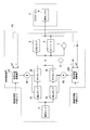
- FIG. 1 is a system configuration diagram of a fuel supply device according to an embodiment of the present disclosure.
- FIG. 3 is a block diagram showing a functional configuration of a fuel supply control device according to an embodiment of the present disclosure.
- FIG. 10 is a block diagram showing a functional configuration of a fuel supply control device according to a modified example of an embodiment of the present disclosure.
- FIG. 8 is a system configuration diagram of a fuel supply device in a modified example of an embodiment of the present disclosure.
- the fuel supply device F is a device for supplying fuel to the gas turbine G as shown in the figure, and more specifically, a device for supplying a predetermined amount of fuel to a plurality of fuel nozzles K provided in a fuel unit of the gas turbine G. ..
- the gas turbine G is an internal combustion engine that is installed in an aircraft as a thrust source for flight, and is a jet engine that obtains thrust by injecting combustion exhaust gas obtained from a fuel device to the rear of the aircraft. That is, the fuel supply device F in the present embodiment is a device provided in an aircraft.
- such a fuel supply device F includes a fuel tank 1, a centrifugal pump 2, a gear pump 3, an electric motor (motor) 4, a pressurizing valve 5, an orifice 6, a first differential pressure gauge 7, and a second differential pressure gauge 7.
- a differential pressure gauge 8, a temperature sensor 9, and a fuel supply control device 10 are provided.
- the fuel tank 1 is a container that stores a predetermined amount of fuel, and supplies the centrifugal pump 2 with fuel.
- the centrifugal pump 2 is a low-pressure pump (non-volumetric pump) that pumps fuel from the fuel tank 1, boosts it to a predetermined pressure, and discharges it as low-pressure fuel to the gear pump 3.
- the gear pump 3 is a high-pressure pump (volumetric pump) that boosts the low-pressure fuel supplied from the centrifugal pump 2 and discharges it as high-pressure fuel toward each fuel nozzle K.
- volumetric pump volumetric pump
- various types of pumps are known, but the gear pump 3 is a pump that boosts the pressure of fuel by the rotation of a pair of gears that mesh with each other, and the rotation shaft of the gears is a journal bearing ( Supported by plain bearings).
- the gear pump 3 also diverts the fuel into the journal bearing to divert the fuel as lubricating oil.
- the electric motor 4 is a power source that rotationally drives the centrifugal pump 2 and the gear pump 3.
- the output shaft of the electric motor 4 is axially coupled to the rotary shaft of the centrifugal pump 2 and the rotary shaft of the gear pump 3 via a predetermined coupling device (not shown). That is, a certain correlation is established between the rotation speed of the electric motor 4 and the rotation speeds of the centrifugal pump 2 and the gear pump 3.
- the pressurizing valve 5 is provided in the middle of the fuel pipe connecting the outlet of the gear pump 3 and the inlet of the fuel nozzle K.
- the pressurizing valve 5 closes when the discharge amount of the gear pump 3 is relatively low, and opens when the discharge amount of the gear pump 3 exceeds a predetermined value.
- the orifice 6 is provided at an intermediate portion of the fuel pipe that connects the discharge port of the gear pump 3 and the inflow port of the fuel nozzle K.
- the pressurizing valve 5 and the orifice 6 form a parallel flow path through a fuel pipe as shown in the figure. That is, the inlet of the pressurizing valve 5 and the inlet of the orifice 6 are both connected to the outlet of the gear pump 3 via the fuel pipe, and the outlet of the pressurizing valve 5 and the outlet of the orifice 6 are both. It is connected to the inlet of the fuel nozzle K via a fuel pipe.
- the pressurizing valve 5 and the orifice 6 as described above constitute a metering valve that detects the flow rate of the fuel supplied from the gear pump 3 to the fuel nozzle K as the fuel supply amount.
- the first differential pressure gauge 7 is a differential pressure transmitter that detects the differential pressure between the upstream side (inlet side) and the downstream side (discharge port side) of the pressurizing valve 5 and the orifice 6 as a front-back differential pressure ⁇ P.
- This front-to-back differential pressure ⁇ P is a physical quantity corresponding to the fuel flow rate, that is, the pressure amount that changes according to the motor rotation speed, that is, the fuel flow rate.
- the first differential pressure gauge 7 outputs the front-rear differential pressure ⁇ P to the fuel supply control device 10.
- the second differential pressure gauge 8 is a differential pressure transmitter that detects the differential pressure between the fuel inflow pressure and the discharge pressure in the gear pump 3 as a boost amount ⁇ P HP .
- the second differential pressure gauge 8 outputs the boost amount ⁇ P HP to the fuel supply control device 10.
- the temperature sensor 9 is a detector that is provided at the discharge port of the gear pump 3 and detects the temperature of the fuel at the discharge port as the fuel temperature T.
- the temperature sensor 9 outputs the fuel temperature T to the fuel supply control device 10.
- the fuel supply control device 10 controls the electric motor 4 based on the above-described differential pressure ⁇ P across the front and rear, the boost amount ⁇ P HP , the fuel temperature T, and the control target value.
- the fuel supply control device 10 is a software control device that generates an operation amount of the electric motor 4 by executing a predetermined control program with predetermined hardware. Note that the above hardware is interposed between a storage device that stores a control program and the like, a CPU (Central Processing Unit) that directly executes the control program, between the CPU and the electric motor 4, and between the CPU and the first differential pressure gauge 7. However, it is an interface circuit for transmitting and receiving various signals.
- a storage device that stores a control program and the like
- a CPU Central Processing Unit
- the fuel supply control device 10 includes, for example, a storage device such as a RAM (Random Access Memory) storing a control program, a ROM (Read Only Memory), an HDD (Hard Disk Drive), an SSD (Solid State Drive), and the control.
- a storage device such as a RAM (Random Access Memory) storing a control program, a ROM (Read Only Memory), an HDD (Hard Disk Drive), an SSD (Solid State Drive), and the control.
- a CPU that executes a program and an input/output device (interface circuit) that exchanges various signals with the CPU interposed between the CPU and the electric motor 4, the first differential pressure gauge 7, and the like are provided.
- Such a fuel supply control device 10 is a functional component realized by cooperation of a control program (software) and hardware, and includes a differential pressure/flow rate conversion table 10a, a subtractor 10b, and a control shown in FIG.
- the calculation unit 10c, the comparator (comparison unit) 10d, the viscosity calculation unit 10e, and the lower limit value calculation unit 10f are provided.
- the differential pressure/flow rate conversion table 10a includes a front and rear differential pressure ⁇ P input as a second detection signal from the first differential pressure gauge 7 and a fuel supply amount (fuel supply amount) supplied from the fuel supply device F to the fuel nozzle K. It is a control table showing the relationship with. That is, the differential pressure/flow rate conversion table 10a is provided with a plurality of fuel supply amount data obtained in advance corresponding to a plurality of front and rear differential pressure data over a predetermined band, and a front and rear differential pressure input from the first differential pressure gauge 7. By searching the data group based on the pressure ⁇ P, the fuel flow rate control amount corresponding to the front-rear differential pressure ⁇ P is output to the subtractor 10b. This fuel flow rate control amount corresponds to the detected flow rate in the present disclosure.
- the subtractor 10b calculates the deviation of the fuel flow rate control amount from the control target value (fuel flow rate deviation), and outputs the fuel flow rate deviation to the control calculation unit 10c. That is, the subtractor 10b calculates the difference between the control target value of the fuel flow rate input from the FADEC (not shown) and the actual fuel flow rate as the control deviation.
- the control target value corresponds to the target flow rate in the present disclosure.
- the control calculation unit 10c generates an operation rotation speed N, which is the operation amount of the electric motor 4, by performing a predetermined calculation process (PID calculation process) on the fuel flow rate deviation input from the subtractor 10b, and the operation rotation speed is calculated. N is output to the comparison unit 10d.
- the operation rotational speed N is an amount that indicates the rotational speed of the electric motor 4, that is, the rotational speed of the gear pump 3.
- Such an operation rotational speed N is an original operation amount in the fuel supply control device 10 according to the present embodiment. Note that the subtractor 10b and the control calculation unit 10c described above configure the operation amount calculation unit in the present disclosure.
- the comparator 10d compares the operation speed N with the lower limit speed Nmin of the gear pump 3 input from the lower limit value calculation unit 10f, selects the larger one as the final operation amount, and outputs it to the motor 4. To do. That is, the comparator 10d outputs the operation speed N to the motor 4 as the final operation amount when the operation speed N is equal to or higher than the lower limit speed Nmin, and when the operation speed N is smaller than the lower limit speed Nmin. In order to protect the journal bearing of the gear pump 3, the lower limit rotation speed Nmin is output to the motor 4 as a final manipulated variable. That is, this operation amount is used to operate the motor 4.
- the viscosity calculator 10e calculates the viscosity coefficient ⁇ (lubricant viscosity) of the lubricating oil (fuel) of the journal bearing in the gear pump 3 based on the fuel temperature T input from the temperature sensor 9 and outputs it to the lower limit calculator 10f. To do.
- the viscosity calculation unit 10e is, for example, a conversion table (fuel temperature/viscosity coefficient conversion table) showing the mutual relationship between the fuel temperature T and the viscosity coefficient ⁇ , and searches for and outputs the viscosity coefficient ⁇ corresponding to the fuel temperature T. ..
- the lower limit value calculation unit 10f calculates the lower limit rotation speed Nmin based on the following equation (1), and outputs the lower limit rotation speed Nmin to the comparator 10d.
- This equation (1) shows the characteristics of the journal bearing in the gear pump 3, and includes the viscosity coefficient ⁇ of the lubricating oil (fuel), the lower limit rotation speed Nmin, the surface pressure P, the shaft diameter r, the minimum gap cmin, and the Sommerfeld.
- the number S is used as a parameter.
- the surface pressure P in the equation (1) is an amount corresponding to the boost amount ⁇ P HP detected by the second differential pressure gauge 8. Further, among these parameters, the shaft diameter r, the minimum gap cmin, and the Sommerfeld number S are stored in advance in the lower limit calculation unit 10f as characteristic data of the journal bearing of the gear pump 3.
- the lower limit value calculation unit 10f receives the shaft diameter r, the minimum gap cmin, the Sommerfeld number S, the viscosity coefficient ⁇ input from the viscosity calculation unit 10e, and the second differential pressure gauge 8 stored in advance.
- the lower limit rotation speed Nmin is calculated for the boost amount ⁇ P HP (contact pressure P) based on the equation (1).
- the bearing clearance c is the minimum gap cmin which is the seizure limit of the journal bearing
- the rotation speed n of the shaft is The lower limit rotational speed Nmin corresponding to the minimum gap cmin is set.
- the lower limit rotation speed Nmin given by the equation (1) is an amount corresponding to the minimum rotation speed at which the journal bearing of the gear pump 3 does not cause the seizure phenomenon.
- the fuel supply amount supplied from the gear pump 3 to each fuel nozzle K is a control target value.
- the centrifugal pump 2 and the gear pump 3 are feedback-controlled by generating the operation speed N (operation amount) so as to be equal to.
- the fuel supply control device 10 generates the operation speed N based on the differential pressure/flow rate conversion table 10a, the subtractor 10b, and the control calculation unit 10c, and outputs the operation speed N to the electric motor 4, that is, the centrifugal motor.
- the pump 2 and the gear pump 3 are rotated at a rotation speed according to the operation rotation speed N.
- the gear pump 3 discharges an amount of fuel equal to the control target value to each fuel nozzle K.
- the comparator 10d, the viscosity calculation unit 10e, and the lower limit value calculation unit 10f determine the lower limit values of the rotation speed of the electric motor 4, that is, the rotation speeds of the centrifugal pump 2 and the gear pump 3. Works to limit.
- the comparator 10d constantly compares the operation rotation speed N input from the control calculation unit 10c with the lower limit rotation speed Nmin input from the lower limit value calculation unit 10f, and the operation rotation speed N is equal to or higher than the lower limit rotation speed Nmin.
- the operation speed N is output to the electric motor 4 as the operation amount, but when the operation speed N is smaller than the lower limit speed Nmin, the lower limit speed Nmin is output to the electric motor 4 as the operation amount.
- the rotational speed of the gear pump 3 is maintained at a higher rotational speed than the minimum rotational speed at which the journal bearing does not cause seizure, so seizure of the journal bearing (sliding bearing) in the gear pump 3 is prevented. Therefore, according to the present embodiment, it is possible to suppress the life reduction and seizure of the gear pump 3 for fuel supply.
- the boost amount ⁇ P HP that is, the surface pressure P of the journal bearing in Expression (1) is acquired by the second differential pressure gauge 8, but the present disclosure is not limited to this.
- a discharge pressure gauge that detects the discharge pressure P HP of the gear pump 3 is provided, and a tachometer that detects the actual rotation speed Nr of the gear pump 3 is newly provided.
- the boost amount ⁇ P HP surface pressure P
- the boost amount ⁇ P HP may be calculated by adopting the fuel supply control device 10A including the boost amount calculation unit (differential pressure calculation unit) 10g.
- the pressure increase amount calculation unit 10g includes the viscosity coefficient ⁇ of the lubricating oil (fuel) input from the viscosity calculation unit 10e, the discharge pressure P HP input from the discharge pressure gauge, and the rotation speed.
- a boost amount ⁇ P HP (contact pressure P) is calculated from the actual rotation speed Nr input from the meter.
- the lower limit value calculation unit 10f in the fuel supply control device 10A calculates the lower limit rotation speed Nmin by substituting the pressure increase amount ⁇ P HP (contact pressure P) input from the pressure increase amount calculation unit 10g into the equation (1). ..
- the gear pump 3 including the journal bearing (sliding bearing) that lubricates fuel is described, but the present disclosure is not limited to this. That is, the present disclosure is also applicable to a gear pump including a journal bearing (slide bearing) of a type that uses a lubricating oil separate from fuel.
- the bearing of the gear pump 3 is not limited to the journal bearing (slide bearing). That is, the present disclosure can be applied to a gear pump that employs a bearing type other than a journal bearing (sliding bearing).
- the method of setting the lower limit rotation speed Nmin is not the equation (1) regarding the journal bearing (sliding bearing), but it is necessary to adopt the one specialized for the bearing to be used.
- the gas turbine G is the fuel supply destination, but the present disclosure is not limited to this.
- An engine other than the gas turbine G may be used as the fuel supply destination.
- the fuel supply device F is configured by a single system including the centrifugal pump 2, the gear pump 3, and the electric motor 4.
- a dual fuel supply device F as shown in FIG. A system fuel supply device F1 may be adopted. That is, in the fuel supply device F1, the first oil supply system including the centrifugal pump 2X, the gear pump 3X, the electric motor 4X, and the fuel supply control device 10X and the centrifugal pump 2Y, the gear pump 3Y, the electric motor 4Y, and the fuel supply control device 10Y.
- a second refueling system composed of
- the fuel supply control device 10X generates the operation speed N1 based on the fuel temperature T input from the temperature sensor 9, the front-back differential pressure ⁇ P input from the first differential pressure gauge 7, and the control target value input from FADEC.
- the electric motor 4X is feedback-controlled.
- the fuel supply control device 10Y determines the operation speed N2 based on the fuel temperature T input from the temperature sensor 9, the front-back differential pressure ⁇ P input from the first differential pressure gauge 7 and the control target value input from FADEC.
- the electric motor 4Y is feedback-controlled by generating the electric motor.
- the electric motor 4X rotates the centrifugal pump 2X and the gear pump 3X at a rotation speed according to the operation rotation speed N1 by rotating according to the operation rotation speed N1 input from the fuel supply control device 10X.
- the electric motor 4Y rotates the centrifugal pump 2Y and the gear pump 3Y at a rotation speed according to the operation rotation speed N2 by rotating according to the operation rotation speed N2 input from the fuel supply control device 10Y.
- the fuel supply device F1 as described above normally supplies the fuel at the flow rate required by the gas turbine G by operating the first refueling system and the second refueling system in parallel. That is, in the fuel supply device F1, the first refueling system and the second refueling system function independently and supply the fuel at the flow rate required by the gas turbine G in a mutually divided manner. Further, in such a fuel supply device F1, when the first refueling system or the second refueling system stops functioning, the one that does not stop supplies the entire amount of fuel required by the gas turbine G.
- the fuel supply device may be configured as a triple system or a quadruple system, if necessary.
- the present disclosure can be used for a fuel supply device that suppresses a life reduction or seizure of a fuel supply gear pump.
Landscapes
- Engineering & Computer Science (AREA)
- Chemical & Material Sciences (AREA)
- Combustion & Propulsion (AREA)
- Mechanical Engineering (AREA)
- General Engineering & Computer Science (AREA)
- Combined Controls Of Internal Combustion Engines (AREA)
- Control Of Positive-Displacement Pumps (AREA)
Abstract
Priority Applications (4)
| Application Number | Priority Date | Filing Date | Title |
|---|---|---|---|
| JP2020571040A JP7095759B2 (ja) | 2019-02-04 | 2019-12-26 | 燃料供給制御装置 |
| US17/427,444 US11867124B2 (en) | 2019-02-04 | 2019-12-26 | Fuel supply control device |
| EP19914392.6A EP3922832B1 (fr) | 2019-02-04 | 2019-12-26 | Dispositif de commande de délivrance de carburant |
| CA3128334A CA3128334C (fr) | 2019-02-04 | 2019-12-26 | Dispositif de commande de delivrance de carburant |
Applications Claiming Priority (2)
| Application Number | Priority Date | Filing Date | Title |
|---|---|---|---|
| JP2019017889 | 2019-02-04 | ||
| JP2019-017889 | 2019-02-04 |
Publications (1)
| Publication Number | Publication Date |
|---|---|
| WO2020162076A1 true WO2020162076A1 (fr) | 2020-08-13 |
Family
ID=71947066
Family Applications (1)
| Application Number | Title | Priority Date | Filing Date |
|---|---|---|---|
| PCT/JP2019/051110 Ceased WO2020162076A1 (fr) | 2019-02-04 | 2019-12-26 | Dispositif de commande de délivrance de carburant |
Country Status (5)
| Country | Link |
|---|---|
| US (1) | US11867124B2 (fr) |
| EP (1) | EP3922832B1 (fr) |
| JP (1) | JP7095759B2 (fr) |
| CA (1) | CA3128334C (fr) |
| WO (1) | WO2020162076A1 (fr) |
Cited By (1)
| Publication number | Priority date | Publication date | Assignee | Title |
|---|---|---|---|---|
| FR3116083A1 (fr) * | 2020-11-06 | 2022-05-13 | Safran Aircraft Engines | Systeme de pompage, aeronef et procede associes |
Families Citing this family (8)
| Publication number | Priority date | Publication date | Assignee | Title |
|---|---|---|---|---|
| WO2015187673A1 (fr) | 2014-06-02 | 2015-12-10 | Afshari Thomas | Ensemble actionneur linéaire et système d'actionneur linéaire |
| US12535071B2 (en) | 2020-07-08 | 2026-01-27 | Project Phoenix, LLC | Dynamic control of gears in a gear pump having a drive-drive configuration |
| EP4179211A1 (fr) * | 2020-07-08 | 2023-05-17 | Project Phoenix, LLC | Commande dynamique d'engrenages dans une pompe à engrenages ayant une configuration entraînement-entraînement |
| FR3120920B1 (fr) * | 2021-03-17 | 2025-06-27 | Safran Helicopter Engines | Systeme de pompage et de dosage d’un fluide pour turbomachine et procede de pilotage d’un tel systeme |
| WO2022195224A1 (fr) * | 2021-03-17 | 2022-09-22 | Safran Helicopter Engines | Systeme de pompage et de dosage d'un fluide pour turbomachine et procede de pilotage d'un tel systeme |
| FR3120919B1 (fr) * | 2021-03-17 | 2024-03-01 | Safran Helicopter Engines | Procede de pilotage d’un systeme de pompage et de dosage d’un fluide pour turbomachine |
| US20220307422A1 (en) * | 2021-03-24 | 2022-09-29 | General Electric Company | Turbine engine system equipped with a fuel deoxygenation system and turboelectric power system |
| US11649768B2 (en) * | 2021-08-20 | 2023-05-16 | Hamilton Sundstrand Corporation | Pump system for a gas turbine engine |
Citations (8)
| Publication number | Priority date | Publication date | Assignee | Title |
|---|---|---|---|---|
| JPS479801B1 (fr) * | 1969-07-09 | 1972-03-23 | ||
| JP2002206486A (ja) * | 2000-12-15 | 2002-07-26 | Carrier Corp | 圧縮機及びその制御方法 |
| JP2008539682A (ja) * | 2005-04-29 | 2008-11-13 | ファールプール・ソシエダッド・アノニマ | コンプレッサの複数のベアリング内の潤滑膜を破断から保護する制御システムと方法 |
| JP2010223118A (ja) * | 2009-03-24 | 2010-10-07 | Ihi Corp | 軸部の軸支構造 |
| JP2013231406A (ja) | 2012-05-01 | 2013-11-14 | Ihi Corp | ガスタービンエンジンの燃料供給装置 |
| JP2014512626A (ja) * | 2011-04-29 | 2014-05-22 | アルバイラー・ゲーエムベーハー | 周波数変換装置を制御するコントローラ、及び制御方法 |
| JP2015052315A (ja) * | 2013-09-09 | 2015-03-19 | 株式会社Ihi | ガスタービンエンジン用の燃料供給システム |
| JP2019017889A (ja) | 2017-07-21 | 2019-02-07 | 株式会社三共 | 遊技機 |
Family Cites Families (6)
| Publication number | Priority date | Publication date | Assignee | Title |
|---|---|---|---|---|
| DE2630222A1 (de) * | 1976-07-06 | 1978-01-19 | Hohenzollern Huettenverwalt | Innenzahnradpumpe oder -motor |
| JP6137780B2 (ja) | 2012-04-26 | 2017-05-31 | 株式会社Ihiエアロスペース | 流体供給装置 |
| JP2015053215A (ja) | 2013-09-09 | 2015-03-19 | 株式会社ジャパンディスプレイ | 有機エレクトロルミネッセンス表示装置及びその製造方法 |
| GB201400153D0 (en) * | 2014-01-06 | 2014-02-19 | Rolls Royce Controls & Data Services Ltd | Enfine fuel control system |
| JP2017082755A (ja) | 2015-10-22 | 2017-05-18 | アスモ株式会社 | 電動ポンプ装置及び電動ポンプ装置の制御方法 |
| GB201614327D0 (en) * | 2016-08-22 | 2016-10-05 | Rolls-Royce Controls And Data Services Ltd | Gear pump bearing |
-
2019
- 2019-12-26 CA CA3128334A patent/CA3128334C/fr active Active
- 2019-12-26 EP EP19914392.6A patent/EP3922832B1/fr active Active
- 2019-12-26 WO PCT/JP2019/051110 patent/WO2020162076A1/fr not_active Ceased
- 2019-12-26 JP JP2020571040A patent/JP7095759B2/ja active Active
- 2019-12-26 US US17/427,444 patent/US11867124B2/en active Active
Patent Citations (8)
| Publication number | Priority date | Publication date | Assignee | Title |
|---|---|---|---|---|
| JPS479801B1 (fr) * | 1969-07-09 | 1972-03-23 | ||
| JP2002206486A (ja) * | 2000-12-15 | 2002-07-26 | Carrier Corp | 圧縮機及びその制御方法 |
| JP2008539682A (ja) * | 2005-04-29 | 2008-11-13 | ファールプール・ソシエダッド・アノニマ | コンプレッサの複数のベアリング内の潤滑膜を破断から保護する制御システムと方法 |
| JP2010223118A (ja) * | 2009-03-24 | 2010-10-07 | Ihi Corp | 軸部の軸支構造 |
| JP2014512626A (ja) * | 2011-04-29 | 2014-05-22 | アルバイラー・ゲーエムベーハー | 周波数変換装置を制御するコントローラ、及び制御方法 |
| JP2013231406A (ja) | 2012-05-01 | 2013-11-14 | Ihi Corp | ガスタービンエンジンの燃料供給装置 |
| JP2015052315A (ja) * | 2013-09-09 | 2015-03-19 | 株式会社Ihi | ガスタービンエンジン用の燃料供給システム |
| JP2019017889A (ja) | 2017-07-21 | 2019-02-07 | 株式会社三共 | 遊技機 |
Cited By (1)
| Publication number | Priority date | Publication date | Assignee | Title |
|---|---|---|---|---|
| FR3116083A1 (fr) * | 2020-11-06 | 2022-05-13 | Safran Aircraft Engines | Systeme de pompage, aeronef et procede associes |
Also Published As
| Publication number | Publication date |
|---|---|
| CA3128334C (fr) | 2023-09-26 |
| US11867124B2 (en) | 2024-01-09 |
| US20220128006A1 (en) | 2022-04-28 |
| JPWO2020162076A1 (ja) | 2021-09-30 |
| EP3922832B1 (fr) | 2023-10-04 |
| CA3128334A1 (fr) | 2020-08-13 |
| EP3922832A4 (fr) | 2022-11-09 |
| JP7095759B2 (ja) | 2022-07-05 |
| EP3922832A1 (fr) | 2021-12-15 |
Similar Documents
| Publication | Publication Date | Title |
|---|---|---|
| WO2020162076A1 (fr) | Dispositif de commande de délivrance de carburant | |
| EP2891781B1 (fr) | Systeme de regulation de carburant d'un moteur | |
| CN114051555B (zh) | 确定用于在飞行器发动机的燃料供给回路中计量燃料的燃料密度的方法 | |
| CN101198784B (zh) | 用于内燃机的燃料喷射系统 | |
| EP2492473B1 (fr) | Système de carburant | |
| EP3228847B1 (fr) | Système et procédé pour l'estimation adaptative de débit de carburant avec réaction de débitmètre | |
| US7762080B2 (en) | Fuel metering pump calibration method | |
| US11629652B2 (en) | Metering pump system | |
| EP2479408B1 (fr) | Système de carburant de moteur d'avion | |
| JP6923069B2 (ja) | 燃料供給制御装置 | |
| CN103917783B (zh) | 监测涡轮机的液压控制系统中的高压泵的容积效率的方法 | |
| EP2672118B1 (fr) | Pompe à engrenages, appareil de pompage comprenant celle-ci et système de carburant d'aéronef comprenant une telle pompe | |
| JP2016503861A (ja) | 複式ポンプ/複式バイパス燃料ポンプシステム | |
| JP5799642B2 (ja) | ガスタービンエンジン用の燃料供給システム | |
| EP3770402B1 (fr) | Ensemble servopompe/moteur hydraulique | |
| CN115492687A (zh) | 管理热燃料的控制方法 | |
| US10451053B2 (en) | Hydromechanical pressure compensation control of a variable displacement pump in a centrifugal pumping and metering system and associated method | |
| CN101490371A (zh) | 内燃机中体积流量可变的容积式泵的调节方法 | |
| RU2308606C1 (ru) | Система топливоподачи и регулирования газотурбинного двигателя | |
| CN113710887B (zh) | 对燃料流量进行调节的涡轮机燃料供应系统 | |
| CN114458475A (zh) | 一种火箭发动机的推进剂供给系统及方法 | |
| JP2026068158A (ja) | ガスタービン用の制御装置、ガスタービン設備及びガスタービンの制御方法 |
Legal Events
| Date | Code | Title | Description |
|---|---|---|---|
| 121 | Ep: the epo has been informed by wipo that ep was designated in this application |
Ref document number: 19914392 Country of ref document: EP Kind code of ref document: A1 |
|
| ENP | Entry into the national phase |
Ref document number: 2020571040 Country of ref document: JP Kind code of ref document: A |
|
| ENP | Entry into the national phase |
Ref document number: 3128334 Country of ref document: CA |
|
| NENP | Non-entry into the national phase |
Ref country code: DE |
|
| ENP | Entry into the national phase |
Ref document number: 2019914392 Country of ref document: EP Effective date: 20210906 |