WO2020162137A1 - Couvercle - Google Patents
Couvercle Download PDFInfo
- Publication number
- WO2020162137A1 WO2020162137A1 PCT/JP2020/001431 JP2020001431W WO2020162137A1 WO 2020162137 A1 WO2020162137 A1 WO 2020162137A1 JP 2020001431 W JP2020001431 W JP 2020001431W WO 2020162137 A1 WO2020162137 A1 WO 2020162137A1
- Authority
- WO
- WIPO (PCT)
- Prior art keywords
- cover
- cover member
- support member
- sensor
- sheet material
- Prior art date
- Legal status (The legal status is an assumption and is not a legal conclusion. Google has not performed a legal analysis and makes no representation as to the accuracy of the status listed.)
- Ceased
Links
Images


Classifications
-
- A—HUMAN NECESSITIES
- A61—MEDICAL OR VETERINARY SCIENCE; HYGIENE
- A61B—DIAGNOSIS; SURGERY; IDENTIFICATION
- A61B50/00—Containers, covers, furniture or holders specially adapted for surgical or diagnostic appliances or instruments, e.g. sterile covers
- A61B50/30—Containers specially adapted for packaging, protecting, dispensing, collecting or disposing of surgical or diagnostic appliances or instruments
-
- A—HUMAN NECESSITIES
- A61—MEDICAL OR VETERINARY SCIENCE; HYGIENE
- A61B—DIAGNOSIS; SURGERY; IDENTIFICATION
- A61B5/00—Measuring for diagnostic purposes; Identification of persons
- A61B5/42—Detecting, measuring or recording for evaluating the gastrointestinal, the endocrine or the exocrine systems
- A61B5/4261—Evaluating exocrine secretion production
- A61B5/4277—Evaluating exocrine secretion production saliva secretion
-
- A—HUMAN NECESSITIES
- A61—MEDICAL OR VETERINARY SCIENCE; HYGIENE
- A61B—DIAGNOSIS; SURGERY; IDENTIFICATION
- A61B5/00—Measuring for diagnostic purposes; Identification of persons
- A61B5/05—Detecting, measuring or recording for diagnosis by means of electric currents or magnetic fields; Measuring using microwaves or radio waves
- A61B5/053—Measuring electrical impedance or conductance of a portion of the body
- A61B5/0537—Measuring body composition by impedance, e.g. tissue hydration or fat content
-
- A—HUMAN NECESSITIES
- A61—MEDICAL OR VETERINARY SCIENCE; HYGIENE
- A61B—DIAGNOSIS; SURGERY; IDENTIFICATION
- A61B5/00—Measuring for diagnostic purposes; Identification of persons
- A61B5/48—Other medical applications
- A61B5/4869—Determining body composition
- A61B5/4875—Hydration status, fluid retention of the body
-
- A—HUMAN NECESSITIES
- A61—MEDICAL OR VETERINARY SCIENCE; HYGIENE
- A61B—DIAGNOSIS; SURGERY; IDENTIFICATION
- A61B5/00—Measuring for diagnostic purposes; Identification of persons
- A61B5/68—Arrangements of detecting, measuring or recording means, e.g. sensors, in relation to patient
- A61B5/6801—Arrangements of detecting, measuring or recording means, e.g. sensors, in relation to patient specially adapted to be attached to or worn on the body surface
- A61B5/6813—Specially adapted to be attached to a specific body part
- A61B5/6814—Head
- A61B5/682—Mouth, e.g., oral cavity; tongue; Lips; Teeth
-
- G—PHYSICS
- G01—MEASURING; TESTING
- G01D—MEASURING NOT SPECIALLY ADAPTED FOR A SPECIFIC VARIABLE; ARRANGEMENTS FOR MEASURING TWO OR MORE VARIABLES NOT COVERED IN A SINGLE OTHER SUBCLASS; TARIFF METERING APPARATUS; MEASURING OR TESTING NOT OTHERWISE PROVIDED FOR
- G01D11/00—Component parts of measuring arrangements not specially adapted for a specific variable
- G01D11/24—Housings ; Casings for instruments
-
- A—HUMAN NECESSITIES
- A61—MEDICAL OR VETERINARY SCIENCE; HYGIENE
- A61B—DIAGNOSIS; SURGERY; IDENTIFICATION
- A61B50/00—Containers, covers, furniture or holders specially adapted for surgical or diagnostic appliances or instruments, e.g. sterile covers
- A61B50/30—Containers specially adapted for packaging, protecting, dispensing, collecting or disposing of surgical or diagnostic appliances or instruments
- A61B2050/3014—Containers specially adapted for packaging, protecting, dispensing, collecting or disposing of surgical or diagnostic appliances or instruments waterproof
-
- A—HUMAN NECESSITIES
- A61—MEDICAL OR VETERINARY SCIENCE; HYGIENE
- A61B—DIAGNOSIS; SURGERY; IDENTIFICATION
- A61B50/00—Containers, covers, furniture or holders specially adapted for surgical or diagnostic appliances or instruments, e.g. sterile covers
- A61B50/30—Containers specially adapted for packaging, protecting, dispensing, collecting or disposing of surgical or diagnostic appliances or instruments
- A61B2050/314—Flexible bags or pouches
-
- A—HUMAN NECESSITIES
- A61—MEDICAL OR VETERINARY SCIENCE; HYGIENE
- A61B—DIAGNOSIS; SURGERY; IDENTIFICATION
- A61B2562/00—Details of sensors; Constructional details of sensor housings or probes; Accessories for sensors
- A61B2562/02—Details of sensors specially adapted for in-vivo measurements
- A61B2562/0209—Special features of electrodes classified in A61B5/24, A61B5/25, A61B5/283, A61B5/291, A61B5/296, A61B5/053
- A61B2562/0214—Capacitive electrodes
-
- A—HUMAN NECESSITIES
- A61—MEDICAL OR VETERINARY SCIENCE; HYGIENE
- A61B—DIAGNOSIS; SURGERY; IDENTIFICATION
- A61B2562/00—Details of sensors; Constructional details of sensor housings or probes; Accessories for sensors
- A61B2562/24—Hygienic packaging for medical sensors; Maintaining apparatus for sensor hygiene
- A61B2562/247—Hygienic covers, i.e. for covering the sensor or apparatus during use
-
- A—HUMAN NECESSITIES
- A61—MEDICAL OR VETERINARY SCIENCE; HYGIENE
- A61B—DIAGNOSIS; SURGERY; IDENTIFICATION
- A61B5/00—Measuring for diagnostic purposes; Identification of persons
- A61B5/05—Detecting, measuring or recording for diagnosis by means of electric currents or magnetic fields; Measuring using microwaves or radio waves
- A61B5/053—Measuring electrical impedance or conductance of a portion of the body
Definitions
- the present disclosure relates to a cover used for a measuring device such as an oral moisture measuring device.
- an intraoral water content measuring device as a measuring device that a measurer holds with a hand to measure an object (see, for example, Patent Document 1).
- This intraoral water content measuring device has a capacitance type sensor and presses the sensor against a measurement site to measure the water content of an object (in the oral cavity).
- a cover is attached so as to cover the measurement surface of the sensor so that the measurement surface of the sensor does not directly touch the object.
- the thickness of the cover that covers the measurement surface of the sensor affects the measurement sensitivity as described above, so a thin cover is used.
- a thin cover may have wrinkles on the measurement surface of the sensor depending on how the cover is attached. The occurrence of such wrinkles affects the measurement result of the oral moisture meter.
- An object of the present disclosure is to provide a cover member capable of suppressing the generation of wrinkles.
- a cover which is one aspect of the present disclosure, is used for a measuring instrument main body having a sensor section having a sensor measurement surface at its tip and a grip section to which the sensor section is connected, and is a bag-like cover that covers the measurement surface.
- a cover member made of resin and covering the measurement surface of the sensor, and arranged at least on the opposite side to the measurement surface with respect to the sensor unit, connected to the cover member, and more than the thickness of the cover member. And a thick support member.
- the support member pulls the cover member to the side opposite to the measurement surface, and the cover member comes into contact with the measurement surface, so that the wrinkle is suppressed from occurring on the cover member on the measurement surface.
- the perspective view of the oral moisture meter The elements on larger scale of a sensor part and a cover.
- the schematic plan view of a cover The schematic side view of a cover.
- (A), (b) is explanatory drawing which shows the supporting member and fixing part of a modification.
- the schematic plan view of the cover of a modification. The schematic side view of the cover of a modification.
- the measuring instrument 1 is, for example, an intraoral moisture measuring instrument that measures the amount of moisture in the oral cavity as a measurement target.
- the measuring instrument 1 has a main body 10 and a cover 40 attached to the main body 10.
- the main body 10 has a grip portion 11 in one end area of the main body 10 in the longitudinal direction and a sensor section 12 in the other end area of the main body 10 in the longitudinal direction.
- the sensor unit 12 extends on the side opposite to the grip unit 11.
- the sensor unit 12 includes a measurement unit 13 at the tip and a connecting unit 14 that connects the measurement unit 13 to the grip unit 11.
- the grip portion 11 is provided with a display portion 11a and a fixed portion 11b.
- the measuring unit 13 is provided with a sensor 20.
- the sensor 20 has a flat plate shape.
- the sensor 20 has a flat measurement surface 20a.
- the sensor 20 is, for example, a capacitance type sensor.
- a pair of electrodes 21a and 21b is provided on the measurement surface 20a of the sensor 20.
- the pair of electrodes 21a and 21b are formed, for example, in a comb shape.
- the pair of electrodes 21a and 21b function as electrodes of the capacitor. That is, the measurement target facing the measurement surface 20a and the liquid on the surface thereof function as a dielectric for the pair of electrodes 21a and 21b.
- the capacitance value of the pair of electrodes 21a and 21b becomes a value according to the measurement target and the amount of water on the surface thereof.
- the measuring instrument 1 includes a circuit board (not shown) on which components such as an oscillation circuit and a control circuit are mounted.
- the oscillator circuit outputs a signal having a frequency corresponding to the capacitance value of the sensor.
- the control circuit detects the amount of water to be measured based on the number of pulses of the output signal of the oscillation circuit. Then, the control circuit displays the detected water content on the display unit 11a.
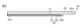
- the cover 40 includes a cover member 50, a support member 60, and a connecting member 70.
- the cover member 50 has a rectangular bag shape.
- the cover member 50 is preferably transparent or translucent.
- the cover 40 is attached so that the cover member 50 covers the measurement unit 13 at the tip of the sensor unit 12.
- the cover member 50 of the present embodiment is a flat bag without a gusset, which is formed in a bag shape and has a first sheet material 51 and a second sheet material 52 connected to an end portion of the first sheet material 51. is there.
- the first sheet material 51 and the second sheet material 52 are connected to each other by, for example, welding.
- the welded portion 50a is indicated by a broken line.
- an end where the first sheet material 51 and the second sheet material 52 are not connected is defined as an open end 50b, and an end opposite to the open end 50b is defined as a tip 50c.
- the cover member 50 may be formed, for example, by folding one sheet material in two and connecting the sheet material in a bag shape. Further, the cover member 50 may be formed by adhesion, adhesion with a double-sided tape, or the like.
- a resin having hydrophobicity can be used as the material of the cover member 50.
- a thermoplastic resin can be used as the resin.
- a resin material for example, polyethylene (PE), polypropylene (PP), polyethylene terephthalate (PET), nylon, polyvinyl chloride, polyimide, or the like can be used.
- the thickness of the cover member 50 is set so that the measurement target of the sensor 20 (for example, the amount of water in the oral cavity) can be measured and the measurement is not hindered.
- the thickness of the cover member 50 may be, for example, 5 ⁇ m or more and 30 ⁇ m or less, and preferably 5 ⁇ m or more and 15 ⁇ m or less.
- the thickness of the cover member 50 can be appropriately changed according to the material of the cover member 50. When the thickness of the cover member 50 is larger than 30 ⁇ m, the sensitivity of the sensor 20 is significantly reduced.
- the thickness can be measured with a contact-type thickness measuring device such as a micrometer, an optical-type thickness measuring device, or the like.
- the support member 60 is connected to the cover member 50 by the connection member 70.
- the connecting member 70 for example, an acrylic or silicone adhesive or adhesive, a double-sided tape, or the like can be used.
- the connecting member 70 is preferably transparent or translucent.
- the support member 60 of this embodiment has a rectangular plate shape. As shown in FIG. 2, the width W2 of the support member 60 is larger than the width W1 of the measurement unit 13. As shown in FIGS. 3 and 4, the support member 60 extends from the front end 50c of the cover member 50 to the open end 50b. Further, the support member 60 is longer than the cover member 50 and protrudes beyond the open end 50b of the cover member 50.
- the support member 60 has a through hole 60a formed in a portion protruding from the cover member 50 so as to penetrate the support member 60 in the thickness direction.
- the through hole 60a is used to fix the cover member 50 to the main body 10 and functions as an engaging portion. That is, the through hole 60a is used to fix the cover 40 to the grip portion 11.
- the support member 60 is preferably transparent or translucent.
- the support member 60 is a highly rigid member.
- a material having higher flexural modulus and flexural strength than the cover member 50 can be used.
- a material for the support member 60 for example, a resin such as PET, ABS, polycarbonate, acrylic, PP, or the like can be used.
- the thickness of the support member 60 can be, for example, 50 ⁇ m or more and 300 ⁇ m or less.
- the thickness of the support member 60 can be set according to its material. For example, when the material of the support member 60 is the same as the material of the cover member 50, it is preferably 2 times or more and 20 times or less, and more preferably 5 times or more the thickness of the cover member 50.
- the thickness of the cover member 50 the thickness of the thickest portion of the cover member 50 or the thickness of the thinnest portion of the cover member 50 can be used. Further, as the thickness of the cover member 50, an average value of the thickness of the thickest portion of the cover member 50 and the thickness of the thinnest portion of the cover member 50 can be used.
- the cover 40 is attached to the grip portion 11 by inserting the fixing portion 11b of the grip portion 11 into the through hole 60a of the support member 60. Then, by removing the support member 60 from the fixed portion 11b of the grip portion 11, the cover 40 is removed from the main body 10. That is, the cover 40 can be attached to and detached from the grip portion 11 by the fixing portion 11 b of the grip portion 11 and the through hole 60 a of the support member 60.
- the cover 40 is attachable to and detachable from the grip portion 11 of the main body 10, that is, attachable and detachable.
- the support member 60 When the cover 40 is attached to the main body 10 so as to cover the measurement surface 20a of the sensor 20 with the cover member 50, the support member 60 has the non-measurement surface 13a side of the measurement unit 13 opposite to the measurement surface 20a of the sensor 20. Is located in.
- the support member 60 has a higher bending elastic modulus than the cover member 50. Therefore, the support member 60 pulls the cover member 50 toward the non-measurement surface 13a of the measurement unit 13.
- the tensile force of the support member 60 acts substantially evenly on the portion covering the four sides of the measuring portion 13 with respect to the cover member 50 that covers the square measuring portion 13, so that the cover member 50 moves the measuring surface 20 a of the sensor 20. In close contact with. At this time, as shown in FIG.
- wrinkles 50z are generated on the cover member 50 at the outer sides of the respective corners of the square-shaped measuring section 13. As described above, by bringing the cover member 50 into close contact with the measurement surface 20a of the sensor 20, the occurrence of wrinkles in the cover member 50 with respect to the measurement surface 20a of the sensor 20 is suppressed.
- the bag shape is a flat bag without a gusset.
- the flat bag without a gusset easily gives tension by the support member 60.
- the gussetless flat bag can be formed only by joining the resin sheets, it can be easily manufactured. It should be noted that it may have a gusseted bag shape.
- the support member 60 extends from the tip 50c of the cover member 50 to the open end 50b. Therefore, after the measurement, the cover member 50 is easily separated from the measurement unit 13 by the support member 60, and the cover member 50 can be easily removed.
- a through hole 60a is formed in the support member 60, and the cover 40 can be easily attached to the main body 10 by engaging the through hole 60a with the fixing portion 11b of the grip portion 11. Further, by removing the through hole 60a of the support member 60 from the fixing portion 11b of the grip portion 11, the cover 40 can be easily removed from the main body 10.
- the support member 60 does not extend when the cover 40 is attached. Therefore, the cover member 50 is pulled and attached to the measurement unit 13. can do.
- the measuring instrument 1 has a main body 10 and a cover 40 attached to the main body 10.
- the main body 10 has a sensor portion 12 having a measurement surface 20a of the sensor 20 at the tip, and a grip portion 11 to which the sensor portion 12 is connected.
- the cover 40 includes a cover member 50 which is made of resin and covers the measurement surface of the sensor 20, and a support member 60 which is disposed at least on the opposite side of the sensor portion 12 from the measurement surface 20a and is connected to the cover member 50.
- the support member 60 has a thickness larger than that of the cover member 50.
- the support member 60 pulls the cover member 50 to the side opposite to the measurement surface 20a, and the cover member 50 contacts the measurement surface 20a. Therefore, wrinkles are generated on the cover member 50 on the measurement surface 20a. Can be suppressed.
- the support member 60 extends from the tip 50c of the cover member 50 to the open end 50b. Therefore, the cover member 50 to which saliva adheres after the measurement is easily separated from the measurement unit 13 by the support member 60, and the cover member 50 can be easily removed.
- each member may be appropriately changed with respect to the above embodiment.
- the sensor unit 12 has a measuring unit 13 in the shape of a long rectangle.
- the measuring device 1 of the measuring unit 13 as described above can easily insert the sensor 20 at the tip into the oral cavity. Also for this sensor unit 12, by using the cover 40 similar to that of the above-described embodiment, it is possible to suppress the generation of wrinkles in the cover member 50 with respect to the measurement surface 20a of the measurement unit 13.
- the through hole 60a is formed in the support member 60 of the cover 40, the fixing portion 11b of the grip portion 11 is inserted into the through hole 60a, and the support member 60 and the fixing portion 11b are engaged to cover the cover 40.
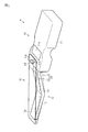
- the engagement structure between the support member 60 and the fixed portion 11b may be changed appropriately.
- the support member 100 is formed with slits 101a and 101b that function as engaging portions, and the fixing portions 11c and 11d provided on the gripping portion 11 are formed with respect to the slits 101a and 101b.
- Engage The fixed portions 11c and 11d extend in a direction orthogonal to the direction from the grip portion 11 to the tip of the sensor portion 12.
- locking portions 11e and 11f are formed at the upper ends of the fixed portions 11c and 11d so as to project in the direction opposite to the tip of the sensor portion 12.
- the locking portions 11e and 11f prevent the support member 60 from coming off the fixed portion 11b.
- the locking portions 11e and 11f having such a shape may be provided on the fixing portion 11b of the above-described embodiment.
- the planar shape of the cover member 50 may be appropriately changed with respect to the above embodiment.
- a shape in which the width increases from the tip 50c toward the opening end 50b for example, the cover member 50 may have a trapezoidal shape.
- the tip 50c is larger than the measuring portion 13 of the sensor portion 12, the cover member 50 is unlikely to be in close contact with the measuring surface 20a of the sensor 20 even when pulled by the support member 60, and wrinkles are more likely to occur. Therefore, in this modified example, the tip 50c does not become larger than the measuring unit 13 of the sensor unit 12, so that the occurrence of wrinkles can be suppressed. Further, since the tip 50c does not become larger than the measuring section 13 of the sensor section 12, it becomes easy to insert it into the oral cavity. Further, by making the opening end 50b wider than the tip 50c, the sensor unit 12 can be easily inserted into the cover member 50.
- the outline shape of the support member 60 may be changed as appropriate in the above embodiment.
- the support member 60 has a shape in which the width becomes narrower from the end portion 60c on the side of the tip 50c of the cover member 50 toward the end portion 60b on the side of the open end 50b of the cover member 50. Is.
- the degree of freedom of the opening shape of the cover member 50 is increased, so that the sensor unit 12 can be easily inserted into the cover member 50. Since the width of the support member 60 at the opening end 50b of the cover member 50 may be narrowed, the width of the portion of the cover member 50 projecting from the opening end 50b can be appropriately changed.
- a holding member 61 may be connected to the first sheet material 51.
- the holding member 61 is arranged on the opposite side of the cover member 50 from the support member 60, and is connected to the cover member 50.
- the holding member 61 is connected to the first sheet material 51 by the connecting member 70, similar to the supporting member 60, for example.
- the holding member 61 is connected to the first sheet material 51 so that the tip of the cover member 50 does not overlap the first sheet material 51, that is, the first sheet material 51 is exposed at the tip of the cover member 50. Accordingly, the measurement surface 20a of the sensor 20 can be pressed against the measurement target via the first sheet material 51. Further, by having the holding member 61 and the supporting member 60, the thin first sheet material 51 and the second sheet material 52 can be easily opened.
- a bag-shaped cover may be formed by connecting the support member 60 and the first sheet material 51 shown in FIG.
- the support member 60 and the second sheet material 52 may be connected to form a bag-shaped cover.
- the support member 60 shown in FIG. 4 may be formed by laminating a plurality of resin sheets. Further, at least one of the first sheet material 51 and the second sheet material 52 may be formed by laminating a plurality of resin sheets.
- SYMBOLS 1 Measuring device, 10... Main body, 11... Gripping part, 11b... Fixed part, 12... Sensor part, 13... Measuring part, 14... Connection part, 20... Sensor, 20a... Measuring surface, 40... Cover, 50... Cover Member, 50b... Open end, 50c... Tip, 51... First sheet material, 52... Second sheet material, 60... Support member, 60a... Through hole, 61... Holding member.
Landscapes
- Health & Medical Sciences (AREA)
- Life Sciences & Earth Sciences (AREA)
- Surgery (AREA)
- Heart & Thoracic Surgery (AREA)
- General Health & Medical Sciences (AREA)
- Public Health (AREA)
- Engineering & Computer Science (AREA)
- Biomedical Technology (AREA)
- Animal Behavior & Ethology (AREA)
- Medical Informatics (AREA)
- Molecular Biology (AREA)
- Veterinary Medicine (AREA)
- Physics & Mathematics (AREA)
- Pathology (AREA)
- Biophysics (AREA)
- Nuclear Medicine, Radiotherapy & Molecular Imaging (AREA)
- Oral & Maxillofacial Surgery (AREA)
- Dentistry (AREA)
- Radiology & Medical Imaging (AREA)
- General Physics & Mathematics (AREA)
- Endocrinology (AREA)
- Gastroenterology & Hepatology (AREA)
- Physiology (AREA)
- Measuring And Recording Apparatus For Diagnosis (AREA)
- Measurement Of The Respiration, Hearing Ability, Form, And Blood Characteristics Of Living Organisms (AREA)
Abstract
Selon l'aspect de la présente invention, il est question d'un élément de couvercle dans lequel la présence de plis peut être supprimée. Dans la présente invention, un dispositif de mesure 1 a un corps 10 et un couvercle 40 fixé au corps 10. Le corps 10 comporte : une partie de capteur 12 ayant, sur sa pointe, une surface de mesure d'un capteur ; et une partie de préhension 11 à laquelle une partie de capteur 12 est connectée. Le couvercle 40 comprend : un élément de couvercle 50 qui est composé d'une résine et recouvre la surface de mesure du capteur ; et un élément de support 60 qui est disposé au moins sur le côté inverse de la surface de mesure par rapport à la partie de capteur 12, est relié à l'élément de couvercle 50, et a l'épaisseur supérieure à l'épaisseur de l'élément de couvercle 50.
Priority Applications (3)
| Application Number | Priority Date | Filing Date | Title |
|---|---|---|---|
| CN202080006834.7A CN113167605B (zh) | 2019-02-04 | 2020-01-17 | 罩 |
| JP2020571065A JP7107396B2 (ja) | 2019-02-04 | 2020-01-17 | カバー |
| US17/318,178 US12109051B2 (en) | 2019-02-04 | 2021-05-12 | Cover |
Applications Claiming Priority (2)
| Application Number | Priority Date | Filing Date | Title |
|---|---|---|---|
| JP2019017730 | 2019-02-04 | ||
| JP2019-017730 | 2019-02-04 |
Related Child Applications (1)
| Application Number | Title | Priority Date | Filing Date |
|---|---|---|---|
| US17/318,178 Continuation US12109051B2 (en) | 2019-02-04 | 2021-05-12 | Cover |
Publications (1)
| Publication Number | Publication Date |
|---|---|
| WO2020162137A1 true WO2020162137A1 (fr) | 2020-08-13 |
Family
ID=71948000
Family Applications (1)
| Application Number | Title | Priority Date | Filing Date |
|---|---|---|---|
| PCT/JP2020/001431 Ceased WO2020162137A1 (fr) | 2019-02-04 | 2020-01-17 | Couvercle |
Country Status (4)
| Country | Link |
|---|---|
| US (1) | US12109051B2 (fr) |
| JP (1) | JP7107396B2 (fr) |
| CN (1) | CN113167605B (fr) |
| WO (1) | WO2020162137A1 (fr) |
Citations (3)
| Publication number | Priority date | Publication date | Assignee | Title |
|---|---|---|---|---|
| JP2008295472A (ja) * | 2007-05-29 | 2008-12-11 | Life:Kk | 口腔機能測定器、口腔機能測定方法、口腔機能測定器用制御装置 |
| WO2014041585A1 (fr) * | 2012-09-13 | 2014-03-20 | テルモ株式会社 | Dispositif de mesure de l'humidité du corps et procédé de commande d'affichage |
| JP2018186880A (ja) * | 2017-04-28 | 2018-11-29 | 株式会社村田製作所 | 測定器 |
Family Cites Families (8)
| Publication number | Priority date | Publication date | Assignee | Title |
|---|---|---|---|---|
| US4993419A (en) * | 1988-12-06 | 1991-02-19 | Exergen Corporation | Radiation detector suitable for tympanic temperature measurement |
| WO2004028359A1 (fr) * | 2002-09-24 | 2004-04-08 | Kabushiki Kaisha Raifu | Procede et instrument permettant de mesurer la teneur en eau de la bouche et couvercle de remplacement pour une partie dudit instrument destinee a etre inseree dans la bouche |
| WO2012124330A1 (fr) * | 2011-03-15 | 2012-09-20 | テルモ株式会社 | Dispositif de mesure d'humidité et dispositif de mesure d'humidité corporelle |
| US9265426B2 (en) * | 2011-12-09 | 2016-02-23 | Remicalm, Llc | Sanitary cover sleeve for medical device with electrical contact |
| WO2015125222A1 (fr) * | 2014-02-19 | 2015-08-27 | 株式会社らいふ | Dispositif de mesure d'humidité intrabuccale |
| CN205720234U (zh) * | 2016-03-16 | 2016-11-23 | 杭州安旭科技有限公司 | 一种样本的收集检测装置 |
| CN206330926U (zh) * | 2016-12-29 | 2017-07-14 | 徐州医科大学 | 手持式表面湿度检测仪器 |
| CN206714761U (zh) * | 2016-12-29 | 2017-12-08 | 徐州医科大学 | 高精度口腔水分检测装置 |
-
2020
- 2020-01-17 JP JP2020571065A patent/JP7107396B2/ja active Active
- 2020-01-17 WO PCT/JP2020/001431 patent/WO2020162137A1/fr not_active Ceased
- 2020-01-17 CN CN202080006834.7A patent/CN113167605B/zh active Active
-
2021
- 2021-05-12 US US17/318,178 patent/US12109051B2/en active Active
Patent Citations (3)
| Publication number | Priority date | Publication date | Assignee | Title |
|---|---|---|---|---|
| JP2008295472A (ja) * | 2007-05-29 | 2008-12-11 | Life:Kk | 口腔機能測定器、口腔機能測定方法、口腔機能測定器用制御装置 |
| WO2014041585A1 (fr) * | 2012-09-13 | 2014-03-20 | テルモ株式会社 | Dispositif de mesure de l'humidité du corps et procédé de commande d'affichage |
| JP2018186880A (ja) * | 2017-04-28 | 2018-11-29 | 株式会社村田製作所 | 測定器 |
Also Published As
| Publication number | Publication date |
|---|---|
| JP7107396B2 (ja) | 2022-07-27 |
| US20210275270A1 (en) | 2021-09-09 |
| US12109051B2 (en) | 2024-10-08 |
| CN113167605A (zh) | 2021-07-23 |
| CN113167605B (zh) | 2023-11-28 |
| JPWO2020162137A1 (ja) | 2021-10-21 |
Similar Documents
| Publication | Publication Date | Title |
|---|---|---|
| JP6863053B2 (ja) | 測定器 | |
| JP2013195118A (ja) | 静電容量式水分センサ、水分測定器 | |
| WO2020162137A1 (fr) | Couvercle | |
| WO2010137612A1 (fr) | Capteur de pression pour langue | |
| US20230277078A1 (en) | Oral pressure measurement device | |
| CN113347918B (zh) | 测定器 | |
| JP7103441B2 (ja) | 測定器 | |
| JP7067671B2 (ja) | 口腔用器具のカバー | |
| JP7287452B2 (ja) | 測定器及び口腔内水分測定器 | |
| JP2022007973A (ja) | 口腔用器具のカバー | |
| WO2019069985A1 (fr) | Boucle | |
| JP3850127B2 (ja) | センサホルダ | |
| JP7279787B2 (ja) | 測定器 | |
| JP5780347B2 (ja) | 生体検査装置 | |
| JP2008058211A (ja) | 密度センサ | |
| WO2022186036A1 (fr) | Élément de couverture pour dispositif de mesure de pression de morsure | |
| JP6805851B2 (ja) | 超音波装置、及び超音波装置の駆動方法 | |
| TW200946082A (en) | Device to measure the muscle of palm and finger | |
| WO2021256080A1 (fr) | Instrument stomatologique | |
| JP2007212209A (ja) | 表面電位センサ | |
| JP2000085827A (ja) | 容 器 | |
| JPH0249641A (ja) | 脂肪厚み測定センサ | |
| TWM414208U (en) | Device to measure the muscle of palm and finger |
Legal Events
| Date | Code | Title | Description |
|---|---|---|---|
| 121 | Ep: the epo has been informed by wipo that ep was designated in this application |
Ref document number: 20752071 Country of ref document: EP Kind code of ref document: A1 |
|
| ENP | Entry into the national phase |
Ref document number: 2020571065 Country of ref document: JP Kind code of ref document: A |
|
| NENP | Non-entry into the national phase |
Ref country code: DE |
|
| 122 | Ep: pct application non-entry in european phase |
Ref document number: 20752071 Country of ref document: EP Kind code of ref document: A1 |