WO2020162251A1 - Dispositif d'estimation de position, système d'estimation de position, serveur d'estimation de position et programme d'estimation de position - Google Patents
Dispositif d'estimation de position, système d'estimation de position, serveur d'estimation de position et programme d'estimation de position Download PDFInfo
- Publication number
- WO2020162251A1 WO2020162251A1 PCT/JP2020/002753 JP2020002753W WO2020162251A1 WO 2020162251 A1 WO2020162251 A1 WO 2020162251A1 JP 2020002753 W JP2020002753 W JP 2020002753W WO 2020162251 A1 WO2020162251 A1 WO 2020162251A1
- Authority
- WO
- WIPO (PCT)
- Prior art keywords
- evaluation function
- rssi
- wireless terminal
- rtt
- terminal station
- Prior art date
- Legal status (The legal status is an assumption and is not a legal conclusion. Google has not performed a legal analysis and makes no representation as to the accuracy of the status listed.)
- Ceased
Links
Images

Classifications
-
- H—ELECTRICITY
- H04—ELECTRIC COMMUNICATION TECHNIQUE
- H04B—TRANSMISSION
- H04B17/00—Monitoring; Testing
- H04B17/20—Monitoring; Testing of receivers
- H04B17/27—Monitoring; Testing of receivers for locating or positioning the transmitter
-
- H—ELECTRICITY
- H04—ELECTRIC COMMUNICATION TECHNIQUE
- H04W—WIRELESS COMMUNICATION NETWORKS
- H04W4/00—Services specially adapted for wireless communication networks; Facilities therefor
- H04W4/02—Services making use of location information
- H04W4/029—Location-based management or tracking services
-
- G—PHYSICS
- G01—MEASURING; TESTING
- G01S—RADIO DIRECTION-FINDING; RADIO NAVIGATION; DETERMINING DISTANCE OR VELOCITY BY USE OF RADIO WAVES; LOCATING OR PRESENCE-DETECTING BY USE OF THE REFLECTION OR RERADIATION OF RADIO WAVES; ANALOGOUS ARRANGEMENTS USING OTHER WAVES
- G01S13/00—Systems using the reflection or reradiation of radio waves, e.g. radar systems; Analogous systems using reflection or reradiation of waves whose nature or wavelength is irrelevant or unspecified
- G01S13/74—Systems using reradiation of radio waves, e.g. secondary radar systems; Analogous systems
- G01S13/76—Systems using reradiation of radio waves, e.g. secondary radar systems; Analogous systems wherein pulse-type signals are transmitted
- G01S13/765—Systems using reradiation of radio waves, e.g. secondary radar systems; Analogous systems wherein pulse-type signals are transmitted with exchange of information between interrogator and responder
-
- G—PHYSICS
- G01—MEASURING; TESTING
- G01S—RADIO DIRECTION-FINDING; RADIO NAVIGATION; DETERMINING DISTANCE OR VELOCITY BY USE OF RADIO WAVES; LOCATING OR PRESENCE-DETECTING BY USE OF THE REFLECTION OR RERADIATION OF RADIO WAVES; ANALOGOUS ARRANGEMENTS USING OTHER WAVES
- G01S13/00—Systems using the reflection or reradiation of radio waves, e.g. radar systems; Analogous systems using reflection or reradiation of waves whose nature or wavelength is irrelevant or unspecified
- G01S13/87—Combinations of radar systems, e.g. primary radar and secondary radar
- G01S13/876—Combination of several spaced transponders or reflectors of known location for determining the position of a receiver
-
- G—PHYSICS
- G01—MEASURING; TESTING
- G01S—RADIO DIRECTION-FINDING; RADIO NAVIGATION; DETERMINING DISTANCE OR VELOCITY BY USE OF RADIO WAVES; LOCATING OR PRESENCE-DETECTING BY USE OF THE REFLECTION OR RERADIATION OF RADIO WAVES; ANALOGOUS ARRANGEMENTS USING OTHER WAVES
- G01S5/00—Position-fixing by co-ordinating two or more direction or position line determinations; Position-fixing by co-ordinating two or more distance determinations
- G01S5/02—Position-fixing by co-ordinating two or more direction or position line determinations; Position-fixing by co-ordinating two or more distance determinations using radio waves
-
- G—PHYSICS
- G01—MEASURING; TESTING
- G01S—RADIO DIRECTION-FINDING; RADIO NAVIGATION; DETERMINING DISTANCE OR VELOCITY BY USE OF RADIO WAVES; LOCATING OR PRESENCE-DETECTING BY USE OF THE REFLECTION OR RERADIATION OF RADIO WAVES; ANALOGOUS ARRANGEMENTS USING OTHER WAVES
- G01S5/00—Position-fixing by co-ordinating two or more direction or position line determinations; Position-fixing by co-ordinating two or more distance determinations
- G01S5/02—Position-fixing by co-ordinating two or more direction or position line determinations; Position-fixing by co-ordinating two or more distance determinations using radio waves
- G01S5/14—Determining absolute distances from a plurality of spaced points of known location
-
- G—PHYSICS
- G01—MEASURING; TESTING
- G01S—RADIO DIRECTION-FINDING; RADIO NAVIGATION; DETERMINING DISTANCE OR VELOCITY BY USE OF RADIO WAVES; LOCATING OR PRESENCE-DETECTING BY USE OF THE REFLECTION OR RERADIATION OF RADIO WAVES; ANALOGOUS ARRANGEMENTS USING OTHER WAVES
- G01S7/00—Details of systems according to groups G01S13/00, G01S15/00, G01S17/00
- G01S7/003—Transmission of data between radar, sonar or lidar systems and remote stations
- G01S7/006—Transmission of data between radar, sonar or lidar systems and remote stations using shared front-end circuitry, e.g. antennas
-
- H—ELECTRICITY
- H04—ELECTRIC COMMUNICATION TECHNIQUE
- H04L—TRANSMISSION OF DIGITAL INFORMATION, e.g. TELEGRAPHIC COMMUNICATION
- H04L43/00—Arrangements for monitoring or testing data switching networks
- H04L43/08—Monitoring or testing based on specific metrics, e.g. QoS, energy consumption or environmental parameters
- H04L43/0852—Delays
- H04L43/0864—Round trip delays
Definitions
- the present invention relates to a position estimating method, a position estimating system, a position estimating server, and a position estimating program for estimating the position of a wireless terminal station based on known positions of a plurality of antennas.
- Non-Patent Document 1 Using a distributed antenna, estimate the position of the wireless terminal station from the round-trip delay time RTT (Round Trip Time) and the received signal strength RSSI (Received Signal Strength Indicator) between multiple known antennas and the terminal. There is a method (Non-Patent Document 1).
- Non-Patent Document 1 the position estimation formula by RTT and the position estimation formula by RSSI are completely independent, and each coordinate is obtained, and two types of coordinates with different accuracy can be obtained. Moreover, the calculation process is completely independent, and it was not possible to integrate the position estimation calculation considering the accuracy of both. Further, in order to obtain one position estimation result, it was necessary to separately obtain two coordinates and then integrate the coordinates.
- Non-Patent Document 1 does not have a specific formula or calculation method for position estimation in two dimensions or three dimensions.
- RTT radio frequency to estimate the 3D position
- RSSI radio frequency
- Non-Patent Document 1 a method using a trajectory is shown in addition to using the GPS calculation method, and it is said that when the two-dimensional position is estimated by RTT, the intersection of two hyperbolas should be obtained.
- the number of antennas is three or more, the number of hyperbolas is two or more, and there may be a case where there is no intersection where all the hyperbolas intersect. In that case, the position could not be estimated.
- the number of antennas is 4 or more, the number of bilobal hyperboloids is 3 or more, and there is no point where all hyperboloids intersect. In that case, the position could not be estimated.
- RSSI as well, if the number of antennas is large, there may occur a case where all circles or spheres do not intersect, and in that case, position estimation could not be performed.
- the coordinates of the position estimation result may deviate significantly, and coordinates outside the range in which the terminal can move (exist) may be output.
- Non-Patent Document 1 uses a distributed antenna, a cost for laying a coaxial cable or the like between the position-known antenna and the AP was required.
- An object of the present invention is to provide a position estimation method, a position estimation system, a position estimation server and a position estimation program that can accurately estimate the position of a wireless terminal station using RTT or/and RSSI.
- a first aspect of the present invention transmits and receives a measurement signal and a response signal between a wireless station having a plurality of n known antennas installed at known positions different from each other and a wireless terminal station having a terminal antenna, and a round trip delay thereof.
- the value obtained by searching the estimated value so that the error evaluation function f error combining the RTT evaluation function and the range evaluation function is minimized is obtained as the position of the wireless terminal station.
- a second aspect of the present invention transmits and receives a measurement signal and a response signal between a radio station including a plurality of n known antennas installed at known positions different from each other and a radio terminal station including a terminal antenna, and receives radio waves thereof.
- the wireless terminal station searches the estimated value so that the solution obtained by arranging the RSSI evaluation functions f ri that evaluates the estimated value of the position or the error evaluation function f error combining the RSSI evaluation functions is minimized. As the position of.
- a third aspect of the present invention transmits/receives a measurement signal and a response signal between a radio station including a plurality of n known antennas installed at known positions different from each other and a radio terminal station including a terminal antenna, and a reception radio wave thereof.
- the value obtained by searching the estimated value so that the error evaluation function f error obtained by combining the RSSI evaluation function and the range evaluation function is minimized is obtained as the position of the wireless terminal station.
- a fourth aspect of the present invention transmits and receives a measurement signal and a response signal between a radio station including a plurality of n known antennas installed at known positions different from each other and a radio terminal station including a terminal antenna, and the round trip delay thereof.
- a fifth aspect of the present invention transmits and receives a measurement signal and a response signal between a radio station including a plurality of n known antennas installed at known positions different from each other and a radio terminal station including a terminal antenna, and the round trip delay thereof.
- a value obtained by searching the estimated value so that the error evaluation function f error is minimized is obtained as the position of the wireless terminal station.
- a sixth invention is, in a position estimation system for estimating the position of a wireless terminal station by the position estimation methods of the first to fifth inventions, an RTT or/and/or RTT measured by a wireless station provided with a plurality of n known antennas.
- the configuration is such that the RSSI is transferred to the position estimation server and the position estimation server calculates the RTT evaluation function f ti or/and the RSSI evaluation function f ri to obtain the position of the wireless terminal station.
- a seventh invention is a position estimation system for estimating the position of a wireless terminal station by the position estimation methods of the first to fifth inventions, wherein a plurality of n known antennas are cables of known length from the wireless base station.
- the distributed antennas are distributed via the RTT and/or the RSSI measured by the radio base station for each distributed antenna to the position estimation server, and the RTT evaluation function f ti or/and RSSI is transmitted by the position estimation server.
- the configuration is such that the evaluation function f ri is calculated to obtain the position of the wireless terminal station.
- An eighth invention is a position estimation server that estimates the position of a wireless terminal station by the position estimation methods of the first to fifth inventions, in which RTT or/and/or RTT measured by each wireless station having a plurality of n known antennas is measured.
- the RSSI is transferred, and the RTT evaluation function f ti and/or the RSSI evaluation function f ri is calculated to obtain the position of the wireless terminal station.
- a position estimation program of a ninth invention causes a computer to execute the processing executed by the position estimation server of the eighth invention, calculates an RTT evaluation function f ti or/and an RSSI evaluation function f ri, and calculates the position of the wireless terminal station. Ask for.
- the present invention can accurately estimate the position of a wireless terminal station using RTT and/or RSSI, and can also perform position estimation that integrates both RTT and RSSI at once. Further, it is possible to consider the accuracy and reliability of both by weighting and to adjust which of RTT and RSSI is more important.
- FIG. 3 is a diagram showing a configuration example of a wireless station 10.
- FIG. 3 is a diagram showing a configuration example of a wireless terminal station 20. It is a figure which shows the example 1 of a sequence of a measurement signal and a response signal. It is a figure which shows the example 2 of a sequence of a measurement signal and a response signal. It is a figure which shows the other whole structural example of the position estimation system of this invention. It is a figure which shows the structural example of the position estimation server 30.
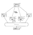
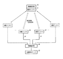
- FIG. 1 shows an example of the overall configuration of the position estimation system of the present invention.
- there are two or more known antennas 11 of the wireless station 10 whose position is known, and the measurement signal and the response signal are exchanged with the terminal antenna 21 of the wireless terminal station 20 whose position is unknown, and RTT or Measure RSSI or both.
- the measured values are collected from each wireless station 10 to the position estimation server 30 via the network.
- the position estimation server 30 performs position estimation calculation and calculates and estimates the positions of the wireless terminal station 20 and the terminal antenna 21.
- FIG. 2 shows a configuration example of the wireless station 10 in the present invention.
- the wireless station 10 includes a signal transmitting unit 12 and a signal receiving unit 13 connected to a known antenna 11, an RTT measuring unit 14 and an RSSI measuring unit 15 connected to the signal receiving unit 13, and a clock 16,
- the position estimation server 30 is connected to the measurement unit 14 and the RSSI measurement unit 15.
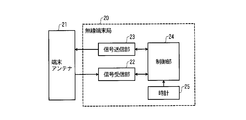
- FIG. 3 shows a configuration example of the wireless terminal station 20 in the present invention.
- the wireless terminal station 20 includes a signal receiving unit 22 and a signal transmitting unit 23 connected to the terminal antenna 21, a control unit 24, and a clock 25 as necessary.
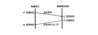
- FIG. 4 shows Example 1 of the sequence of the measurement signal and the response signal.
- the wireless station 10 transmits a measurement signal to the wireless terminal station 20, and the wireless terminal station 20 returns a response signal to the wireless station.
- a wireless LAN action frame or management frame can be used for the measurement signal. Since the wireless terminal station 20 receiving them returns ACK, this can be used as a response signal. Of course, other types of frames such as data frames may be used for the measurement signal and the response signal. Other than the wireless LAN, another wireless communication system capable of exchanging the measurement signal and the response signal may be used.
- the radio station 10 When measuring the RTT, the radio station 10 records the time t1 using the clock 16 when transmitting the measurement signal from the RTT measurement unit 14 via the signal transmission unit 12.
- the wireless terminal station 20 transmits the response signal from the signal transmitting unit 23.
- the clock 25 may be used to record the reception time t2 of the measurement signal and the transmission time t3 of the response signal.
- the RTT measuring unit 14 records the time t4 using the clock 16.
- the RTT measurement unit 14 can obtain the RTT including the terminal delay time (t3-t2), which is the delay time of the wireless terminal station 20, by calculating (t4-t1). This is called raw RTT.
- the clock 25 of the wireless terminal station 20 is unnecessary.
- the wireless terminal station 20 When the wireless terminal station 20 is equipped with the clock 25 and can record t2 and t3, a method of putting the terminal delay time (t3-t2), or putting t2 and t3 itself in the response signal, or putting it in another signal, etc. May be transmitted to the wireless station 10. Then, by calculating ((t4-t1)---(t3-t2)), the RTT excluding the terminal delay time can be obtained. This is a non-delayed RTT.
- the wireless station 10 causes the RSSI measuring unit 15 to acquire the RSSI when the signal receiving unit 13 receives the response signal.
- FIG. 5 shows Example 2 of the sequence of the measurement signal and the response signal.
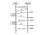
- FTM Freine Timing Measurement
- the RTT measurement unit 14 as an initiator transmits an Initial FTM Request from the signal transmission unit 12 to the radio terminal station 20 and transmits the measurement signal to the radio terminal station 20 a specified number of times. Request to.
- the control unit 24 starts the operation as the responder.
- the wireless terminal station 20 transmits FTM1 as the first measurement signal from the signal transmission unit 23, and the control unit 24 uses the clock 25 to record the transmission time as t1.
- the wireless station 10 returns ACK as a response signal.
- the RTT measuring unit 14 uses the clock 16 to record the reception time as t2 and the transmission time as t3.
- the wireless terminal station 20 When receiving the ACK, the wireless terminal station 20 transmits the next measurement signal FTM2. At this time, the control unit 24 uses the clock 25 to record the reception time t4 and the transmission time t1′.
- the second and subsequent measurement signals include the previous transmission time t1 and reception time t4.
- the wireless station 10 can receive the previous measurement signal including (t1, t4), and together with the previous reception time t2 and transmission time t3 recorded in the RTT measurement unit 14, (( By calculating t4-t1)---(t3-t2)), the non-delayed RTT in the round trip between the previous measurement signal and the response signal can be obtained.
- the wireless station 10 triggers the non-delay RTT between the wireless station 10 and the wireless terminal station 20. It can be measured.
- the wireless station 10 causes the RSSI measuring unit 15 to acquire the RSSI when the signal receiving unit 13 receives the measurement signals FTM1, FTM2 and the like.
- the distributed antennas have already been installed and no new cable laying cost is incurred
- the plurality of sets of the wireless stations 10 and the known antennas 11 in FIG. It may be replaced with a plurality of distributed antennas 42 connected via 41.
- the raw RTT, the non-delayed RTT, and the RSSI are corrected in consideration of the loss and the delay caused by passing through the cable 41, so that it is possible to obtain a measurement value equivalent to the configuration as shown in FIG.
- An estimation calculation method can be used.
- the wireless station 10 or the wireless base station 40 can measure a part or all of the raw RTT, the non-delayed RTT, and the RSSI. Tell 30.
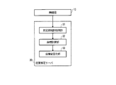
- FIG. 7 shows a configuration example of the position estimation server 30 in the present invention.
- the position estimation server 30 includes a measurement value statistical processing unit 31, a coordinate calculation unit 32, and a coordinate stabilization unit 33 connected to the wireless station 10.
- (2.1) Measured value statistical processing unit 31 Since the wireless terminal station 20 does not only perform the processing of the measurement signal and the response signal but also performs other processing at the same time, the terminal delay time varies depending on the status of other processing. Therefore, in the case of a configuration in which only raw RTT can be measured, the measured value statistical processing unit 31 performs statistical processing for each known antenna 11 and obtains a statistical processing RTT from which variations are removed by methods such as removal of outliers and moving average or regression. May be. In the case of the non-delayed RTT, the terminal delay time is not included and the variation is small, and thus the statistical processing is optional. Similarly, for RSSI, it is optional to perform statistical processing.
- the measurement value statistical processing unit 31 may calculate the reliability of the RTT measurement value or the RSSI measurement value, which is an index of accuracy, for each known antenna 11. For example, if the number of measurements in the past fixed period is large, the reliability of the measured value of the known antenna 11 is high, and if the variance or standard deviation of the measured values in the past fixed period is small, the reliability of the measured value of the known antenna 11 is high. It can be calculated based on the criteria such as. Further, the reliability can be corrected according to the characteristics, location, and surrounding conditions of each known antenna 11.
- the number of measurements in the past fixed period is s
- the standard deviation is ⁇
- the correction factor for each known antenna 11 is a size
- the correction offset is b size
- the standard deviation is a sigma
- the correction offset of the standard deviation is b sigma
- Coordinate calculation unit 32 does not need to distinguish between the raw RTT, the non-delayed RTT, and the statistical processing RTT, and therefore any one is treated as an RTT for calculation.
- the coordinates of the known antenna i are (x i , y i ) in the case of two dimensions and (x i , y i , z i ) in the case of three dimensions. These are known and the unit of coordinates is m. Let the RTT measured with the known antenna i be trti [s]. The RSSI measured with the known antenna i is RSSI i [dBm].
- the cable length, or other measured values for each known antenna i it is corrected in advance. For example, if the cable length connecting a known antenna i is longer than the other known antenna cable delay than other known antenna, since the cable loss increases from t rti other by subtracting the reciprocal of cable delay corrects the known antenna conditions equivalent to t rti is obtained by adding the cable loss in RSSI i condition equivalent RSSI i other known antenna previously performed correction obtained.
- the coordinates of the terminal antenna 21 are (x s , y s ) in the case of two dimensions and (x s , y s , z s ) in the case of three dimensions. These are unknown and the unit of coordinates is m.
- the sum of the terminal delay time and the other delay time is t d [s]. This is also unknown.
- the speed of light c is set to 299792458 [m/s]. This is exactly the same constant in any space.
- the coordinates x s , y s, and l d of the terminal antenna 21 are three, and in the three-dimensional case, the coordinates x s , y s , z s, and l d of the terminal antenna 21 are calculated. There will be four.
- searching for these unknowns to find the coordinates of the terminal antenna 21 As the estimated values during the search, three variables of x, y, l in the case of two dimensions and four variables of x, y, z, l in the case of three dimensions are used.
- the distance between the coordinate of the estimated value and the known antenna i is d i (x, y) in the case of two dimensions. In the case of three dimensions, d i (x, y, z) Becomes
- the estimated value of the true distance which can be obtained from the estimated value l of the difference between the pseudo distance and the true distance, is l pi- 1 Obviouslys If the respective estimated values are correct, the two agree.
- the difference between these values is defined as the RTT evaluation function f ti for evaluating the estimated value as follows.
- Two-dimensional case: f ti (x, y, l) d i (x, y)-(l pi -1)
- Three-dimensional case: f ti (x, y, z, l) d i (x, y, z)-(l pi -1)
- the unknowns to be obtained are three-dimensional coordinates x s , y s and r B of the terminal antenna 21 in the case of two dimensions, and coordinates x s , y s , z of the terminal antenna 21 in the case of three dimensions.
- s and r B There are four, s and r B.
- the RSSI evaluation function f ri for evaluating the estimated value is defined as follows, as in the RTT.
- Range evaluation function A range evaluation function is provided to give a penalty to the evaluation value when the estimated value such as coordinates is out of the movable (presence) range of the terminal.
- the range evaluation function is zero when the estimated value is within the range, and when the estimated value is outside the range, the value is increased according to the degree of deviation.
- the estimated value is x min ⁇ x ⁇ x max y min ⁇ y ⁇ y max l min ⁇ l ⁇ l max r min ⁇ r ⁇ r max
- the solution x, y, z, l can be obtained and the position can be estimated. It is difficult to solve this system of equations analytically because it is non-linear, but the solution can be obtained using the Newton method.
- the least squares method is used together to obtain the solution. Further, in that case, by using the weighted least squares method in which the reliability w of the RTT measurement value for each known antenna is used as a weight and each corresponding equation is weighted, position estimation with higher accuracy becomes possible. ..
- the solution can be obtained by the Newton method combined with the least squares method. Furthermore, for the equation of the RTT evaluation function, the reliability w of the RTT measurement value of the corresponding known antenna is used as the weight, and for the equation of the RSSI evaluation function, the reliability w of the RSSI measurement value of the corresponding known antenna is used as the weight.
- the weighted least squares method used, more accurate position estimation can be performed. Further, by relatively increasing or decreasing the RTT weight and the RSSI weight, it is possible to adjust which measurement value is to be emphasized.
- the reliability of the RTT measurement value of the known antenna i is weighted w ti
- the reliability of the RSSI measurement value is weighted w ri
- the weight of the range evaluation function is w L.
- RTT range evaluation function
- the maximum parameters of the error evaluation function are x, y, z, l, and r, but in the case of two dimensions, z disappears, l does not exist when RTT is not used, and r does not use RSSI. Disappear. Since either RTT or RSSI must be used, the minimum number of x, y, l combs is x, y, r.
- the minimum may be searched by the Newton method, a quasi-Newton method algorithm such as the L-BFGS method, or a Bayesian optimization may be used. More simply, there is a method to perform a brute force search within a certain range at a certain interval, or a method of first searching at a rough interval and then sequentially searching the surroundings where the evaluation value is likely to be low at a fine interval. is there.
- all parameters may be searched, but there is also a method of not searching l or r by obtaining l or r that minimizes the error evaluation function from the estimated value of the coordinate.
- the estimated value of coordinates in two dimensions is (x ⁇ , y ⁇ )
- the partial differentiation of l or r of the error evaluation function may be taken to find l or r at which it becomes zero.
- x ⁇ and y ⁇ are x hat and y hat. That is,
- the r that satisfies the above is found, and each is used as an estimated value of l and r at the coordinate (x ⁇ , y ⁇ ), and the error evaluation function is evaluated.
- this method only the coordinates need be searched, and the search space can be greatly reduced.
- Coordinate stabilizing unit 33 Even if the terminal antenna 21 is stationary, the coordinates obtained by the coordinate calculation unit 32 (hereinafter, instantaneous value coordinates) may vibrate finely. Therefore, the coordinate stabilizing unit 33 may obtain the coordinates (hereinafter, stabilizing coordinates) from which the fine vibration is removed.
- a certain threshold value is set as “play”, and stabilization is performed by changing the stabilization coordinate so as not to exceed the threshold value only when the difference between the instantaneous value coordinate and the stabilization coordinate point or the distance exceeds the threshold value. be able to.
- the stabilized coordinates may be obtained by passing the instantaneous value coordinates through an LPF or Kalman filter to remove small vibrations.
- each unit of the position estimation server 30 described above can be realized by a computer program that causes a computer to function.
- This computer program can be stored in a computer-readable storage medium or can be provided via a network.
- wireless station 11 known antenna 12 signal transmitting unit 13 signal receiving unit 14 RTT measuring unit 15 RSSI measuring unit 16 clock 20 wireless terminal station 21 terminal antenna 22 signal receiving unit 23 signal transmitting unit 24 control unit 25 clock 30 position estimation server 31 measurement Value statistical processing unit 32 Coordinate calculation unit 33 Coordinate stabilization unit 40 Radio base station 41 Cable 42 Distributed antenna
Landscapes
- Engineering & Computer Science (AREA)
- Radar, Positioning & Navigation (AREA)
- Remote Sensing (AREA)
- Computer Networks & Wireless Communication (AREA)
- Physics & Mathematics (AREA)
- General Physics & Mathematics (AREA)
- Signal Processing (AREA)
- Environmental & Geological Engineering (AREA)
- Electromagnetism (AREA)
- Position Fixing By Use Of Radio Waves (AREA)
- Quality & Reliability (AREA)
Abstract
L'invention concerne un procédé d'estimation de position consistant : à transmettre et à recevoir un signal de mesure et un signal de réponse entre une station sans fil comprenant une pluralité de n antennes connues installées à différentes positions connues et une station de terminal sans fil comprenant une antenne de terminal; et à mesurer un temps de délai aller-retour (RTT) et un indicateur d'intensité de signal reçu (RSSI) de la transmission et de la réception afin d'estimer la position de la station de terminal sans fil, la position de la station de terminal sans fil étant déterminée par le calcul simultané d'une fonction d'évaluation de RTT fti permettant d'évaluer une valeur d'estimation de la position de la station de terminal sans fil estimée à partir du RTT mesuré entre la station de terminal sans fil et l'antenne connue i (i = 1, 2,..., n) et d'une fonction d'évaluation de RSSI fri permettant d'évaluer une valeur d'estimation de la position de la station de terminal sans fil estimée à partir du RSSI, afin de trouver une solution, ou de rechercher une valeur d'estimation de manière à réduire au minimum une erreur de fonction d'évaluation d'erreur ferror obtenue par la combinaison de la fonction d'évaluation de RTT et de la fonction d'évaluation de RSSI.
Priority Applications (1)
| Application Number | Priority Date | Filing Date | Title |
|---|---|---|---|
| US17/428,270 US12010586B2 (en) | 2019-02-06 | 2020-01-27 | Position estimation method, position estimation system, position estimation server, and position estimation program |
Applications Claiming Priority (2)
| Application Number | Priority Date | Filing Date | Title |
|---|---|---|---|
| JP2019-020139 | 2019-02-06 | ||
| JP2019020139A JP7120061B2 (ja) | 2019-02-06 | 2019-02-06 | 位置推定方法、位置推定システム、位置推定サーバおよび位置推定プログラム |
Publications (1)
| Publication Number | Publication Date |
|---|---|
| WO2020162251A1 true WO2020162251A1 (fr) | 2020-08-13 |
Family
ID=71947293
Family Applications (1)
| Application Number | Title | Priority Date | Filing Date |
|---|---|---|---|
| PCT/JP2020/002753 Ceased WO2020162251A1 (fr) | 2019-02-06 | 2020-01-27 | Dispositif d'estimation de position, système d'estimation de position, serveur d'estimation de position et programme d'estimation de position |
Country Status (3)
| Country | Link |
|---|---|
| US (1) | US12010586B2 (fr) |
| JP (1) | JP7120061B2 (fr) |
| WO (1) | WO2020162251A1 (fr) |
Citations (9)
| Publication number | Priority date | Publication date | Assignee | Title |
|---|---|---|---|---|
| JP2000244967A (ja) * | 1999-02-24 | 2000-09-08 | Mitsubishi Electric Corp | 移動体通信システム、該システムを構成する移動機および基地局、並びに該システムにおける移動機の位置検出方法 |
| JP2004053510A (ja) * | 2002-07-23 | 2004-02-19 | Nippon Telegr & Teleph Corp <Ntt> | 位置検出システム |
| JP2008178006A (ja) * | 2007-01-22 | 2008-07-31 | Hitachi Ltd | 無線ノード位置推定方法、システム、及びその処理装置 |
| JP2009002886A (ja) * | 2007-06-25 | 2009-01-08 | Brother Ind Ltd | 測距システム及び測位システム |
| JP2009281793A (ja) * | 2008-05-20 | 2009-12-03 | Brother Ind Ltd | 移動局測位システム |
| JP2010146180A (ja) * | 2008-12-17 | 2010-07-01 | Mitsubishi Electric Corp | 物品管理端末および物品管理システム |
| JP2010190629A (ja) * | 2009-02-17 | 2010-09-02 | Oki Electric Ind Co Ltd | 位置推定装置、無線端末、位置推定システム |
| JP2012509483A (ja) * | 2008-11-21 | 2012-04-19 | クアルコム,インコーポレイテッド | 調整されたラウンドトリップ時間測定を使用した無線位置決定 |
| JP2013174472A (ja) * | 2012-02-24 | 2013-09-05 | Toshiba Corp | 位置推定装置、位置推定システム、および位置推定方法 |
Family Cites Families (5)
| Publication number | Priority date | Publication date | Assignee | Title |
|---|---|---|---|---|
| JP4972741B2 (ja) | 2006-10-13 | 2012-07-11 | 国立大学法人三重大学 | 焼酎カスの利用方法 |
| JP5134624B2 (ja) * | 2007-07-06 | 2013-01-30 | 株式会社エヌ・ティ・ティ・ドコモ | 移動通信システムにおける基地局装置及び指向性制御方法 |
| US9307432B2 (en) * | 2013-01-03 | 2016-04-05 | Qualcomm Incorporated | Processing delay estimate based on crowdsourcing data |
| US20160255471A1 (en) * | 2015-02-27 | 2016-09-01 | Qualcomm Incorporated | Distribution and utilization of antenna information for location determination operations |
| US10736074B2 (en) * | 2017-07-31 | 2020-08-04 | Qualcomm Incorporated | Systems and methods to facilitate location determination by beamforming of a positioning reference signal |
-
2019
- 2019-02-06 JP JP2019020139A patent/JP7120061B2/ja active Active
-
2020
- 2020-01-27 US US17/428,270 patent/US12010586B2/en active Active
- 2020-01-27 WO PCT/JP2020/002753 patent/WO2020162251A1/fr not_active Ceased
Patent Citations (9)
| Publication number | Priority date | Publication date | Assignee | Title |
|---|---|---|---|---|
| JP2000244967A (ja) * | 1999-02-24 | 2000-09-08 | Mitsubishi Electric Corp | 移動体通信システム、該システムを構成する移動機および基地局、並びに該システムにおける移動機の位置検出方法 |
| JP2004053510A (ja) * | 2002-07-23 | 2004-02-19 | Nippon Telegr & Teleph Corp <Ntt> | 位置検出システム |
| JP2008178006A (ja) * | 2007-01-22 | 2008-07-31 | Hitachi Ltd | 無線ノード位置推定方法、システム、及びその処理装置 |
| JP2009002886A (ja) * | 2007-06-25 | 2009-01-08 | Brother Ind Ltd | 測距システム及び測位システム |
| JP2009281793A (ja) * | 2008-05-20 | 2009-12-03 | Brother Ind Ltd | 移動局測位システム |
| JP2012509483A (ja) * | 2008-11-21 | 2012-04-19 | クアルコム,インコーポレイテッド | 調整されたラウンドトリップ時間測定を使用した無線位置決定 |
| JP2010146180A (ja) * | 2008-12-17 | 2010-07-01 | Mitsubishi Electric Corp | 物品管理端末および物品管理システム |
| JP2010190629A (ja) * | 2009-02-17 | 2010-09-02 | Oki Electric Ind Co Ltd | 位置推定装置、無線端末、位置推定システム |
| JP2013174472A (ja) * | 2012-02-24 | 2013-09-05 | Toshiba Corp | 位置推定装置、位置推定システム、および位置推定方法 |
Also Published As
| Publication number | Publication date |
|---|---|
| JP2020126030A (ja) | 2020-08-20 |
| US12010586B2 (en) | 2024-06-11 |
| JP7120061B2 (ja) | 2022-08-17 |
| US20220109955A1 (en) | 2022-04-07 |
Similar Documents
| Publication | Publication Date | Title |
|---|---|---|
| US7969913B2 (en) | Localization apparatus for recognizing location of node in sensor network and method thereof | |
| US9817112B2 (en) | Pairwise measurements for improved position determination | |
| CN103379427B (zh) | 一种定位方法、设备及系统 | |
| US10534065B2 (en) | Estimation of a level for an observation data set | |
| KR101040705B1 (ko) | 무선 측위 시스템 및 측위 방법 | |
| EP3173807B1 (fr) | Système et procédé d'estimation d'emplacement basé sur rssi fiable et précise | |
| KR101163335B1 (ko) | 수신신호강도의 거리 추정 방식에 의거한 실내 무선 측위 방법 및 이 방법을 실시하기 위한 프로그램이 기록된 기록매체 | |
| US20160249316A1 (en) | Non-line-of-sight (nlos) and line-of-sight (los) classification techniques for indoor ranging | |
| WO2020209053A1 (fr) | Procédé d'estimation de position, système d'estimation de position, serveur d'estimation de position et programme d'estimation de position | |
| JP6251930B2 (ja) | 位置推定システム | |
| KR102299605B1 (ko) | 다중 경로 완화를 이용한 위치 결정 시스템 및 방법 | |
| KR20120115895A (ko) | 수신신호강도의 거리추정방식에 의거하여 4개 이상의 앵커노드를 이용한 실내 무선 측위 방법 및 이 방법을 실시하기 위한 프로그램이 기록된 기록매체 | |
| Mukhopadhyay et al. | Novel RSSI evaluation models for accurate indoor localization with sensor networks | |
| KR20090043733A (ko) | 실내 위치결정방법 및 장치 | |
| CA2775023A1 (fr) | Estimation de la position d'un dispositif utilisateur dans un reseau sans fil | |
| KR20160090853A (ko) | Rtt-기반 실내 위치확인 시스템을 배치시키기 위한 시스템 및 방법 | |
| BR112017020558B1 (pt) | Método, aparelho e dispositivo para obter tempo de chegada quando um terminal móvel é localizado | |
| CN102472810B (zh) | 用于校准基于传播时间的定位系统的方法 | |
| KR102246959B1 (ko) | 다수 앵커노드 사이의 상쇄간섭을 이용한 tdoa 방식의 무선측위 방법 및 그 장치 | |
| Baba | Calibrating time of flight in two way ranging | |
| KR101219913B1 (ko) | 이동 노드 위치 추정 방법 | |
| WO2020162251A1 (fr) | Dispositif d'estimation de position, système d'estimation de position, serveur d'estimation de position et programme d'estimation de position | |
| CN114173413B (zh) | 一种基于Wi-Fi精准时间测量的无线定位方法 | |
| KR20250117441A (ko) | 송신기의 위치를 구하는 방법 | |
| JP6607190B2 (ja) | 位置推定装置、位置推定システム、方法および記録媒体 |
Legal Events
| Date | Code | Title | Description |
|---|---|---|---|
| 121 | Ep: the epo has been informed by wipo that ep was designated in this application |
Ref document number: 20752691 Country of ref document: EP Kind code of ref document: A1 |
|
| NENP | Non-entry into the national phase |
Ref country code: DE |
|
| 122 | Ep: pct application non-entry in european phase |
Ref document number: 20752691 Country of ref document: EP Kind code of ref document: A1 |