WO2020162277A1 - Matériau actif d'électrode positive pour batterie secondaire et batterie secondaire - Google Patents
Matériau actif d'électrode positive pour batterie secondaire et batterie secondaire Download PDFInfo
- Publication number
- WO2020162277A1 WO2020162277A1 PCT/JP2020/003095 JP2020003095W WO2020162277A1 WO 2020162277 A1 WO2020162277 A1 WO 2020162277A1 JP 2020003095 W JP2020003095 W JP 2020003095W WO 2020162277 A1 WO2020162277 A1 WO 2020162277A1
- Authority
- WO
- WIPO (PCT)
- Prior art keywords
- spectrum
- positive electrode
- active material
- electrode active
- concentration
- Prior art date
- Legal status (The legal status is an assumption and is not a legal conclusion. Google has not performed a legal analysis and makes no representation as to the accuracy of the status listed.)
- Ceased
Links
Images


Classifications
-
- H—ELECTRICITY
- H01—ELECTRIC ELEMENTS
- H01M—PROCESSES OR MEANS, e.g. BATTERIES, FOR THE DIRECT CONVERSION OF CHEMICAL ENERGY INTO ELECTRICAL ENERGY
- H01M4/00—Electrodes
- H01M4/02—Electrodes composed of, or comprising, active material
- H01M4/36—Selection of substances as active materials, active masses, active liquids
- H01M4/362—Composites
- H01M4/366—Composites as layered products
-
- H—ELECTRICITY
- H01—ELECTRIC ELEMENTS
- H01M—PROCESSES OR MEANS, e.g. BATTERIES, FOR THE DIRECT CONVERSION OF CHEMICAL ENERGY INTO ELECTRICAL ENERGY
- H01M10/00—Secondary cells; Manufacture thereof
- H01M10/05—Accumulators with non-aqueous electrolyte
- H01M10/052—Li-accumulators
-
- H—ELECTRICITY
- H01—ELECTRIC ELEMENTS
- H01M—PROCESSES OR MEANS, e.g. BATTERIES, FOR THE DIRECT CONVERSION OF CHEMICAL ENERGY INTO ELECTRICAL ENERGY
- H01M10/00—Secondary cells; Manufacture thereof
- H01M10/05—Accumulators with non-aqueous electrolyte
- H01M10/052—Li-accumulators
- H01M10/0525—Rocking-chair batteries, i.e. batteries with lithium insertion or intercalation in both electrodes; Lithium-ion batteries
-
- H—ELECTRICITY
- H01—ELECTRIC ELEMENTS
- H01M—PROCESSES OR MEANS, e.g. BATTERIES, FOR THE DIRECT CONVERSION OF CHEMICAL ENERGY INTO ELECTRICAL ENERGY
- H01M10/00—Secondary cells; Manufacture thereof
- H01M10/05—Accumulators with non-aqueous electrolyte
- H01M10/056—Accumulators with non-aqueous electrolyte characterised by the materials used as electrolytes, e.g. mixed inorganic/organic electrolytes
- H01M10/0564—Accumulators with non-aqueous electrolyte characterised by the materials used as electrolytes, e.g. mixed inorganic/organic electrolytes the electrolyte being constituted of organic materials only
- H01M10/0566—Liquid materials
-
- H—ELECTRICITY
- H01—ELECTRIC ELEMENTS
- H01M—PROCESSES OR MEANS, e.g. BATTERIES, FOR THE DIRECT CONVERSION OF CHEMICAL ENERGY INTO ELECTRICAL ENERGY
- H01M4/00—Electrodes
- H01M4/02—Electrodes composed of, or comprising, active material
- H01M4/13—Electrodes for accumulators with non-aqueous electrolyte, e.g. for lithium-accumulators; Processes of manufacture thereof
- H01M4/131—Electrodes based on mixed oxides or hydroxides, or on mixtures of oxides or hydroxides, e.g. LiCoOx
-
- H—ELECTRICITY
- H01—ELECTRIC ELEMENTS
- H01M—PROCESSES OR MEANS, e.g. BATTERIES, FOR THE DIRECT CONVERSION OF CHEMICAL ENERGY INTO ELECTRICAL ENERGY
- H01M4/00—Electrodes
- H01M4/02—Electrodes composed of, or comprising, active material
- H01M4/36—Selection of substances as active materials, active masses, active liquids
- H01M4/48—Selection of substances as active materials, active masses, active liquids of inorganic oxides or hydroxides
- H01M4/50—Selection of substances as active materials, active masses, active liquids of inorganic oxides or hydroxides of manganese
- H01M4/505—Selection of substances as active materials, active masses, active liquids of inorganic oxides or hydroxides of manganese of mixed oxides or hydroxides containing manganese for inserting or intercalating light metals, e.g. LiMn2O4 or LiMn2OxFy
-
- H—ELECTRICITY
- H01—ELECTRIC ELEMENTS
- H01M—PROCESSES OR MEANS, e.g. BATTERIES, FOR THE DIRECT CONVERSION OF CHEMICAL ENERGY INTO ELECTRICAL ENERGY
- H01M4/00—Electrodes
- H01M4/02—Electrodes composed of, or comprising, active material
- H01M4/36—Selection of substances as active materials, active masses, active liquids
- H01M4/48—Selection of substances as active materials, active masses, active liquids of inorganic oxides or hydroxides
- H01M4/52—Selection of substances as active materials, active masses, active liquids of inorganic oxides or hydroxides of nickel, cobalt or iron
- H01M4/525—Selection of substances as active materials, active masses, active liquids of inorganic oxides or hydroxides of nickel, cobalt or iron of mixed oxides or hydroxides containing iron, cobalt or nickel for inserting or intercalating light metals, e.g. LiNiO2, LiCoO2 or LiCoOxFy
-
- H—ELECTRICITY
- H01—ELECTRIC ELEMENTS
- H01M—PROCESSES OR MEANS, e.g. BATTERIES, FOR THE DIRECT CONVERSION OF CHEMICAL ENERGY INTO ELECTRICAL ENERGY
- H01M10/00—Secondary cells; Manufacture thereof
- H01M10/05—Accumulators with non-aqueous electrolyte
- H01M10/058—Construction or manufacture
- H01M10/0585—Construction or manufacture of accumulators having only flat construction elements, i.e. flat positive electrodes, flat negative electrodes and flat separators
-
- H—ELECTRICITY
- H01—ELECTRIC ELEMENTS
- H01M—PROCESSES OR MEANS, e.g. BATTERIES, FOR THE DIRECT CONVERSION OF CHEMICAL ENERGY INTO ELECTRICAL ENERGY
- H01M4/00—Electrodes
- H01M4/02—Electrodes composed of, or comprising, active material
- H01M2004/021—Physical characteristics, e.g. porosity, surface area
-
- H—ELECTRICITY
- H01—ELECTRIC ELEMENTS
- H01M—PROCESSES OR MEANS, e.g. BATTERIES, FOR THE DIRECT CONVERSION OF CHEMICAL ENERGY INTO ELECTRICAL ENERGY
- H01M4/00—Electrodes
- H01M4/02—Electrodes composed of, or comprising, active material
- H01M2004/026—Electrodes composed of, or comprising, active material characterised by the polarity
- H01M2004/028—Positive electrodes
-
- H—ELECTRICITY
- H01—ELECTRIC ELEMENTS
- H01M—PROCESSES OR MEANS, e.g. BATTERIES, FOR THE DIRECT CONVERSION OF CHEMICAL ENERGY INTO ELECTRICAL ENERGY
- H01M50/00—Constructional details or processes of manufacture of the non-active parts of electrochemical cells other than fuel cells, e.g. hybrid cells
- H01M50/10—Primary casings; Jackets or wrappings
- H01M50/102—Primary casings; Jackets or wrappings characterised by their shape or physical structure
- H01M50/105—Pouches or flexible bags
-
- Y—GENERAL TAGGING OF NEW TECHNOLOGICAL DEVELOPMENTS; GENERAL TAGGING OF CROSS-SECTIONAL TECHNOLOGIES SPANNING OVER SEVERAL SECTIONS OF THE IPC; TECHNICAL SUBJECTS COVERED BY FORMER USPC CROSS-REFERENCE ART COLLECTIONS [XRACs] AND DIGESTS
- Y02—TECHNOLOGIES OR APPLICATIONS FOR MITIGATION OR ADAPTATION AGAINST CLIMATE CHANGE
- Y02E—REDUCTION OF GREENHOUSE GAS [GHG] EMISSIONS, RELATED TO ENERGY GENERATION, TRANSMISSION OR DISTRIBUTION
- Y02E60/00—Enabling technologies; Technologies with a potential or indirect contribution to GHG emissions mitigation
- Y02E60/10—Energy storage using batteries
-
- Y—GENERAL TAGGING OF NEW TECHNOLOGICAL DEVELOPMENTS; GENERAL TAGGING OF CROSS-SECTIONAL TECHNOLOGIES SPANNING OVER SEVERAL SECTIONS OF THE IPC; TECHNICAL SUBJECTS COVERED BY FORMER USPC CROSS-REFERENCE ART COLLECTIONS [XRACs] AND DIGESTS
- Y02—TECHNOLOGIES OR APPLICATIONS FOR MITIGATION OR ADAPTATION AGAINST CLIMATE CHANGE
- Y02P—CLIMATE CHANGE MITIGATION TECHNOLOGIES IN THE PRODUCTION OR PROCESSING OF GOODS
- Y02P70/00—Climate change mitigation technologies in the production process for final industrial or consumer products
- Y02P70/50—Manufacturing or production processes characterised by the final manufactured product
Definitions
- the present technology relates to a positive electrode active material for a secondary battery containing a layered rock salt type lithium nickel composite oxide and a secondary battery using the positive electrode active material for the secondary battery.
- This secondary battery includes an electrolyte solution together with a positive electrode and a negative electrode, and the positive electrode contains a positive electrode active material.
- a particulate lithium composite oxide (Li x Ni y Co z X (1-yz) O w ) having lithium borate on the surface is used ( See, for example, Patent Document 1.).
- a particulate lithium composite oxide (Li x Ni 1- y My O 2+ ⁇ ) in which the amount of alkali on the particle surface is set within a predetermined range ) is used (for example, refer to Patent Document 2).
- a lithium composite oxide (Li x (Ni 1-y Co) set so that the peak intensity ratio calculated based on the analysis result of X-ray photoelectron spectroscopy falls within a predetermined range.
- y ) 1-z M z O 2 is used (for example, refer to Patent Document 3).
- the present technology has been made in view of such problems, and an object thereof is to provide a positive electrode active material for a secondary battery and a secondary battery capable of obtaining excellent battery characteristics.
- a positive electrode active material for a secondary battery covers a central portion including a layered rock salt type lithium nickel composite oxide represented by the following formula (1), and covers the surface of the central portion. And a coating portion containing a boron compound.
- the crystallite size of the (104) plane calculated using the X-ray diffraction method and Scherrer's formula is 40.0 nm or more and 74.5 nm or less.
- the specific surface area measured using the BET specific surface area measuring method satisfies the condition represented by the following formula (2).
- the first element concentration ratio which is calculated based on the C1s spectrum and O1s spectrum measured using X-ray photoelectron spectroscopy and is represented by the following formula (3), is 0.08 or more and 0.80 or less. .. It is calculated based on the Li1s spectrum, Ni2p 3/2 spectrum, Co2p 3/2 spectrum, Mn2p 1/2 spectrum and Al2s spectrum measured using X-ray photoelectron spectroscopy and is represented by the following formula (4).
- the second element concentration ratio is 0.60 or more and 1.50 or less.
- the third element concentration ratio is 0.15 or more and 0.90 or less.
- M is cobalt (Co), iron (Fe), manganese (Mn), copper (Cu), zinc (Zn), aluminum (Al), chromium (Cr), vanadium (V), titanium (Ti), magnesium) It is at least one of (Mg) and zirconium (Zr), and a, b and c satisfy 0.8 ⁇ a ⁇ 1.2, 0 ⁇ b ⁇ 0.4 and 0 ⁇ c ⁇ 3. )
- Z is the crystallite size (nm) of the (104) plane.
- A is the specific surface area (m 2 /g).
- R1 I1/I2 (3)
- R1 is the first element concentration ratio.
- I1 is the CO 3 concentration (atom %) calculated based on the C1s spectrum.
- I2 is the Me—O concentration (atom calculated based on the O1s spectrum.
- Me—O is an O-derived oxidation that is bound to Li, Ni or M in the formula (1) and has a binding energy of 528 eV or more and 531 eV or less. It is a thing.
- R2 I3/I4 (4)
- R2 is the second element concentration ratio.
- I3 is the Li concentration (atomic %) calculated based on the Li1s spectrum.
- I4 is the Ni2p3 /2 spectrum, Co2p3 /2 spectrum, Mn2p1 / 2 is the sum of the Ni concentration (atomic %), the Co concentration (atomic %), the Mn concentration (atomic %), and the Al concentration (atomic %) calculated based on the 2 spectrum and the Al2s spectrum.
- R3 I5/I4 (5)
- R3 is the third element concentration ratio.
- I4 is the Ni concentration (atomic %) and the Co concentration calculated based on the Ni2p3 / 2 spectrum, Co2p3 /2 spectrum, Mn2p1 /2 spectrum and Al2s spectrum.
- I5 is B concentration (Atomic %) calculated based on the B1s spectrum.
- a secondary battery according to an embodiment of the present technology includes a positive electrode including a positive electrode active material, a negative electrode, and an electrolytic solution, and the positive electrode active material is the same as the positive electrode active material for a secondary battery according to the embodiment of the present invention described above. It has a configuration of.
- the positive electrode active material for a secondary battery or the secondary battery of one embodiment of the present technology since the positive electrode active material has the above-described configuration and physical properties, excellent battery characteristics can be obtained.
- the effect of the present technology is not necessarily limited to the effect described here, and may be any one of a series of effects related to the present technology described later.
- FIG. 3 is a plan view showing the configuration of the positive electrode current collector shown in FIG. 2.
- FIG. 3 is a plan view showing the configuration of the negative electrode current collector shown in FIG. 2.
- FIG. 3 is a plan view schematically showing a configuration of a positive electrode active material according to an embodiment of the present technology. It is a figure showing the appropriate range regarding the specific surface area (crystallite size) of a positive electrode active material. It is a top view for explaining an analysis range of X-ray photoelectron spectroscopy, and a measurement range of a Walder method. It is a figure showing an example of the volume-based particle size distribution regarding a positive electrode active material.
- FIG. 9 is an exploded perspective view showing a configuration of a secondary battery of Modification 1.
- Secondary battery 1-1 Configuration 1-1-1. Overall configuration 1-1-2. Composition and Physical Properties of Positive Electrode Active Material 1-2. Operation 1-3. Manufacturing method 1-3-1. Manufacturing method of positive electrode active material 1-3-2. Manufacturing method of secondary battery 1-4. Action and effect 2. Modification 3. Secondary battery applications
- This secondary battery is a lithium-ion secondary battery whose battery capacity is obtained by utilizing the phenomenon of lithium (lithium ion) occlusion and release, as described below.
- composition> the overall configuration of the secondary battery will be described, and then the configuration and physical properties of the positive electrode active material will be described.
- FIG. 1 illustrates an exploded perspective configuration of a secondary battery 10 that is a secondary battery according to an embodiment of the present technology.
- FIG. 2 shows a sectional configuration of the electrode body 20 shown in FIG.
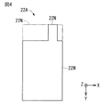
- FIG. 3 shows the planar configuration of the positive electrode current collector 21A shown in FIG. 2
- FIG. 4 shows the planar configuration of the negative electrode current collector 22A shown in FIG.
- FIG. 1 shows a state in which the electrode body 20 and the exterior member 30 (the first member 30A and the second member 30B) are separated from each other.
- FIG. 2 shows a state before the plurality of positive electrode current collectors 21A (the positive electrode current collector exposed portions 21N shown in FIG. 3) are bonded to each other, and the plurality of negative electrode current collectors 22A (FIG. 4). It shows a state before the negative electrode collector exposed portions 22N) shown in are joined to each other.
- the secondary battery 10 includes, for example, as shown in FIG. 1, a laminated electrode body 20 which is a battery element, and a film-shaped exterior member 30. That is, the secondary battery 10 described here is, for example, a laminate film type non-aqueous electrolyte secondary battery in which the rectangular electrode body 20 is housed inside the exterior member 30.
- the secondary battery 10 can be made compact, lightweight and thin.
- the positive electrode lead 11 and the negative electrode lead 12 are attached to the electrode body 20.
- the electrode body 20 has a main surface 20A and a main surface 20B opposite to the main surface 20A.
- the main surface 20A has a side portion 20C in the longitudinal direction and a side portion in the lateral direction. 20D and.
- the positive electrode lead 11 and the negative electrode lead 12 are led out in the same direction from the inside of the exterior member 30 to the outside, and have, for example, a thin plate shape or a mesh shape.
- the positive electrode lead 11 and the negative electrode lead 12 include, for example, a metal material such as aluminum, copper, nickel or stainless steel.
- the adhesion film 13 contains a material having adhesion to the positive electrode lead 11 and the negative electrode lead 12, for example, a polyolefin resin such as polyethylene, polypropylene, modified polyethylene or modified polypropylene.
- the exterior member 30 has, for example, flexibility and stores the electrode body 20 (the positive electrode 21, the negative electrode 22, the electrolytic solution, and the like).
- the exterior member 30 includes, for example, two films (first member 30A and second member 30B) separated from each other, and the first member 30A and the second member 30B are separated by the electrode body 20. Overlaid on top of each other. Since the four sides of each of the first member 30A and the second member 30B are in close contact with each other, a close contact portion is formed at the peripheral edge of each of the first member 30A and the second member 30B.
- the first member 30A has a housing 31 for housing the electrode body 20, and the housing 31 is formed by, for example, deep drawing.
- the exterior member 30 is, for example, a laminate film in which a heat-sealing resin layer, a metal layer, and a surface protective layer are laminated in this order from the inside (the side close to the electrode body 20).
- the heat-sealing resin layer contains, for example, a polymer material such as polypropylene or polyethylene.
- the metal layer contains, for example, a metal material such as aluminum.
- the surface protective layer contains, for example, a polymer material such as nylon.
- the exterior member 30 is, for example, an aluminum laminate film in which a polyethylene film, an aluminum foil, and a nylon film are laminated in this order from the inside.
- the outer edge portions (heat-sealing resin layers) of the first member 30A and the second member 30B are in close contact with each other using, for example, a fusion treatment or an adhesive.
- the exterior member 30 may be a laminated film having another laminated structure, a polymer film such as polypropylene, or a metal film instead of the above-mentioned aluminum laminated film. Further, the exterior member 30 may be a laminated film in which a polymer film is laminated on one side or both sides of an aluminum foil.
- the electrode body 20 includes, for example, as shown in FIGS. 1 and 2, a positive electrode 21, a negative electrode 22, a separator 23, and an electrolytic solution which is a liquid electrolyte.
- a plurality of positive electrodes 21 and a plurality of negative electrodes 22 are alternately laminated with a separator 23 in between, and the electrolytic solution is impregnated in each of the positive electrode 21, the negative electrode 22, and the separator 23.
- the electrochemical capacity per unit area of the negative electrode 22 is smaller than the electrochemical capacity per unit area of the positive electrode 21. Is also preferably large.
- the positive electrode 21 includes, for example, as shown in FIG. 2, a positive electrode current collector 21A and a positive electrode active material layer 21B provided on both surfaces of the positive electrode current collector 21A.
- the positive electrode active material layer 21B may be provided only on one surface of the positive electrode current collector 21A.
- the positive electrode current collector 21A has, for example, as shown in FIG. 3, a rectangular positive electrode active material layer forming portion 21M in which the positive electrode active material layer 21B is formed and a rectangular positive electrode active material layer 21B in which the positive electrode active material layer 21B is not formed.
- the positive electrode collector exposed portion 21N is included.
- the positive electrode active material layer 21B is formed on both surfaces of the positive electrode active material layer forming portion 21M.
- the positive electrode collector exposed portion 21N is a portion where a part of the positive electrode active material layer forming portion 21M is extended, and has a width narrower than the width (dimension in the X-axis direction) of the positive electrode active material layer forming portion 21M.
- the positive electrode collector exposed portion 21N may have the same width as the width of the positive electrode active material layer forming portion 21M.
- the plurality of positive electrode current collector exposed portions 21N are joined together, and the positive electrode lead 11 is joined to the plurality of positive electrode current collector exposed portions 21N joined together.
- the cathode current collector 21A is, for example, a metal foil such as an aluminum foil, a nickel foil, or a stainless foil.
- the positive electrode active material layer 21B contains a positive electrode active material capable of inserting and extracting lithium, which is an electrode reactant, and the positive electrode active material is in the form of particles.
- the positive electrode active material layer 21B may contain any one kind or two or more kinds of additives such as a binder and a conductive agent, if necessary.
- the positive electrode active material contains any one kind or two or more kinds of positive electrode materials capable of inserting and extracting lithium, and the positive electrode material contains a lithium-containing compound.
- This lithium-containing compound is a general term for compounds containing lithium (Li) as a constituent element.
- the lithium-containing compound is a layered rock salt type lithium nickel composite oxide represented by the following formula (1). That is, the lithium nickel composite oxide has a layered rock salt type crystal structure. This is because a high battery capacity can be stably obtained even when the battery voltage is low. Since the composition (a) of lithium differs depending on the charge/discharge state, the value of a represents the value in the completely discharged state.
- M is cobalt (Co), iron (Fe), manganese (Mn), copper (Cu), zinc (Zn), aluminum (Al), chromium (Cr), vanadium (V), titanium (Ti), magnesium) It is at least one of (Mg) and zirconium (Zr), and a, b and c satisfy 0.8 ⁇ a ⁇ 1.2, 0 ⁇ b ⁇ 0.4 and 0 ⁇ c ⁇ 3. )
- this lithium-nickel composite oxide is a composite oxide containing nickel (Ni) as a constituent element together with lithium, and any one of the additional metal elements (M) may be added as necessary.
- Ni nickel
- M additional metal elements
- the lithium nickel composite oxide is, for example, any one of compounds represented by the following formulas (1-1), (1-2) and (1-3) Or contains two or more types.
- M1 is at least one of iron (Fe), copper (Cu), zinc (Zn), chromium (Cr), vanadium (V), titanium (Ti), magnesium (Mg) and zirconium (Zr).
- A, b, c, d and e are 0.8 ⁇ a ⁇ 1.2, 0 ⁇ b ⁇ 0.2, 0 ⁇ c ⁇ 0.1, 0 ⁇ d ⁇ 0.1, 0 ⁇ e ⁇ 3 and 0 ⁇ (b+c+d) ⁇ 0.3 are satisfied.
- M2 is at least one of iron (Fe), copper (Cu), zinc (Zn), chromium (Cr), vanadium (V), titanium (Ti), magnesium (Mg) and zirconium (Zr).
- A, b, c, d and e are 0.8 ⁇ a ⁇ 1.2, 0 ⁇ b ⁇ 0.4, 0 ⁇ c ⁇ 0.4, 0 ⁇ d ⁇ 0.1, 0 ⁇ e ⁇ 3 and 0.1 ⁇ (b+c+d) ⁇ 0.7 are satisfied.
- M3 is at least one of iron (Fe), copper (Cu), zinc (Zn), chromium (Cr), vanadium (V), titanium (Ti), magnesium (Mg) and zirconium (Zr).
- A, b, c, d, e and f are 0.8 ⁇ a ⁇ 1.2, 0 ⁇ b ⁇ 0.2, 0 ⁇ c ⁇ 0.1, 0 ⁇ d ⁇ 0.1, 0 ⁇ e ⁇ 0.1, 0 ⁇ f ⁇ 3 and 0 ⁇ (b+c+d+e) ⁇ 0.3 are satisfied.
- the compound represented by the formula (1-1) is a nickel-cobalt-aluminum-based lithium nickel composite oxide.
- the compound represented by the formula (1-2) is a nickel cobalt manganese-based lithium nickel composite oxide.
- the compound represented by the formula (1-3) is a nickel-cobalt-manganese-aluminum-based lithium nickel composite oxide.
- the compound represented by the formula (1-1) corresponds to the compound represented by the formula (1-1).
- the compound represented by the formula (1-1) is, for example, LiNiO 2 , LiNi 0.9 Co 0.1 O 2 , LiNi 0.85 Co 0.1 Al 0.05 O 2 , LiNi 0.90 Co 0.05 Al 0.05 O 2 , LiNi 0.82 Co 0.14 Al 0.04 O 2 , LiNi 0.78 Co 0.18 Al 0.04 O 2 and LiNi 0.90 Co 0.06 Al 0.04 O 2 and the like.
- Examples of the compound represented by the formula (1-2) include LiNi 0.5 Co 0.2 Mn 0.3 O 2 , LiNi 0.8 Co 0.1 Mn 0.1 O 2 , LiNi 0.9 Co 0.05 Mn 0.05 O 2 , LiNi 0.3 Co 0.3 Mn 0.3 O 2, and LiNi 0.84 Co 0.08 Mn 0.08 O 2 and the like.
- the compound represented by the formula (1-3) is, for example, LiNi 0.80 Co 0.10 Mn 0.05 Al 0.05 O 2 .
- the surface of the lithium nickel composite oxide is covered with a boron compound.
- the positive electrode active material positive electrode material
- This boron compound is a general term for compounds containing boron (B) as a constituent element. This is because the surface of the lithium nickel composite oxide is electrochemically stabilized, so that the decomposition reaction of the electrolytic solution on the surface of the lithium nickel composite oxide is suppressed.
- the type of boron compound is not particularly limited, and examples thereof include boric acid (H 3 BO 3 ), lithium tetraborate (Li 2 B 4 O 7 ), ammonium pentaborate (NH 4 B 5 O 8 ), and metaboric acid.
- examples include lithium (LiBO 2 ) and boron oxide (B 2 O 3 ).
- a positive electrode active material containing a lithium nickel composite oxide whose surface is coated with a boron compound as a positive electrode material has predetermined configurations and physical properties in order to improve the battery characteristics of the secondary battery 10. Details of the constitution and physical properties of this positive electrode active material will be described later.
- the positive electrode active material may further contain any one kind or two or more kinds of other positive electrode materials (other lithium-containing compounds).
- the other lithium-containing compound may be a layered rock salt-type other lithium-containing compound, a spinel-type lithium-containing compound, or an olivine-type lithium-containing compound.
- Another lithium-containing compound of the layered rock salt type is, for example, a lithium composite oxide such as LiCoO 2 .
- the spinel-type lithium-containing compound is, for example, a lithium composite oxide such as LiMn 2 O 4 .
- the olivine-type lithium-containing compound is, for example, a lithium phosphate compound such as LiFePO 4 , LiMnPO 4 and LiMn 0.5 Fe 0.5 PO 4 .
- the positive electrode active material may further contain any one kind or two or more kinds of compounds (non-lithium containing compound) not containing lithium as a constituent element.
- This non-lithium-containing compound is, for example, an inorganic compound such as MnO 2 , V 2 O 5 , V 6 O 13 , NiS and MoS.
- the binder contains, for example, one kind or two or more kinds of polymer materials such as polyvinylidene fluoride, polytetrafluoroethylene, polyacrylonitrile, styrene butadiene rubber and carboxymethyl cellulose.
- the binder may be, for example, a copolymer of two or more polymer materials.
- the conductive agent contains, for example, one kind or two or more kinds of carbon materials such as graphite, carbon black and Ketjen black.
- the conductive agent may be, for example, a metal material or a conductive polymer material as long as the material has conductivity.
- the negative electrode 22 includes, for example, as shown in FIG. 2, a negative electrode current collector 22A and a negative electrode active material layer 22B provided on both surfaces of the negative electrode current collector 22A.
- the negative electrode active material layer 22B may be provided only on one surface of the negative electrode current collector 22A.
- the negative electrode current collector 22A has, for example, as shown in FIG. 4, a rectangular negative electrode active material layer forming portion 22M in which the negative electrode active material layer 22B is formed and a rectangular negative electrode active material layer 22B in which the negative electrode active material layer 22B is not formed.
- the negative electrode collector exposed portion 22N is included.
- the negative electrode active material layer 22B is formed on both surfaces of the negative electrode active material layer forming portion 22M.
- the negative electrode collector exposed portion 22N is a portion where a part of the negative electrode active material layer forming portion 22M is extended, and has a width narrower than the width (dimension in the X-axis direction) of the negative electrode active material layer forming portion 22M.
- the negative electrode collector exposed portion 22N is arranged so as not to overlap the positive electrode collector exposed portion 21N. However, as shown by the chain double-dashed line in FIG. 4, the negative electrode collector exposed portion 22N may have the same width as the negative electrode active material layer forming portion 22M.
- the negative electrode current collector exposed portions 22N are bonded to each other, and the negative electrode lead 12 is bonded to the negative electrode current collector exposed portions 22N that are bonded to each other.
- the negative electrode current collector 22A is, for example, a metal foil such as a copper foil, a nickel foil, or a stainless foil.
- the negative electrode active material layer 22B contains, for example, a negative electrode active material capable of inserting and extracting lithium, which is an electrode reactant.
- the negative electrode active material layer 22B may include any one kind or two or more kinds of additives such as a binder and a conductive agent, if necessary. The details regarding the binder and the conductive agent are as described above.
- the negative electrode active material contains any one kind or two or more kinds of negative electrode materials capable of inserting and extracting lithium, and the negative electrode materials are, for example, carbon materials and metal-based materials.
- the negative electrode material may be both a carbon material and a metallic material (mixture).
- the carbon materials are, for example, non-graphitizable carbon, graphitizable carbon, graphite, pyrolytic carbons, cokes, glassy carbons, organic polymer compound fired bodies, carbon fibers and activated carbon.
- a metal-based material is a material containing one or more of metal elements and metalloid elements as constituent elements.
- This metallic material may be an alloy, a compound or a mixture.
- the metallic material may be crystalline or amorphous.
- the metal element and the metalloid element include magnesium (Mg), boron (B), aluminum (Al), titanium (Ti), gallium (Ga), indium (In), silicon (Si), germanium (Ge), Tin (Sn), Lead (Pb), Bismuth (Bi), Cadmium (Cd), Silver (Ag), Zinc (Zn), Hafnium (Hf), Zirconium (Zr), Yttrium (Y), Palladium (Pd) and For example, platinum (Pt).
- the alloy may be an alloy composed of two or more kinds of metal elements, may contain one or more kinds of metal elements and one or more kinds of metalloid elements, or may contain one or more kinds of non-metal elements. Good.
- the structure of the alloy is, for example, a solid solution, a eutectic (eutectic mixture), an intermetallic compound, or a coexisting structure of two or more kinds thereof.
- the compound is, for example, an oxide.
- the negative electrode material may be, for example, a metal oxide or a polymer material.
- the metal oxide is, for example, a lithium composite oxide, iron oxide, ruthenium oxide, molybdenum oxide, or the like
- the lithium composite oxide is, for example, a lithium titanium composite oxide such as lithium titanate (Li 4 Ti 5 O 12 ). It is a thing.
- the polymer material is, for example, polyacetylene, polyaniline, polypyrrole, or the like.
- the separator 23 is interposed between the positive electrode 21 and the negative electrode 22, and allows lithium ions to pass while preventing a short circuit caused by the contact between the positive electrode 21 and the negative electrode 22.
- the separator 23 is, for example, a porous film containing one kind or two or more kinds of a polymer material and a ceramic material, and may be a laminated body of two or more kinds of porous films.
- the polymer material is, for example, polyethylene, polypropylene, polytetrafluoroethylene, or the like, and may be a mixture of two or more kinds thereof, or a copolymer of two or more kinds thereof.
- the electrolytic solution contains a solvent and an electrolyte salt, and may further contain any one kind or two or more kinds of additives.
- the solvent is, for example, a non-aqueous solvent
- the electrolytic solution containing the non-aqueous solvent is a so-called non-aqueous electrolytic solution.
- the type of solvent non-aqueous solvent may be only one type, or may be two or more types.
- the non-aqueous solvent is, for example, cyclic carbonic acid ester, chain carbonic acid ester, lactone, chain carboxylic acid ester, nitrile (mononitrile) compound, unsaturated cyclic carbonic acid ester, halogenated carbonic acid ester, sulfonic acid ester. , Acid anhydrides, dicyano compounds (dinitrile compounds), diisocyanate compounds and phosphoric acid esters. This is because excellent capacity characteristics, cycle characteristics and storage characteristics can be obtained.
- the cyclic carbonic acid ester is, for example, ethylene carbonate, propylene carbonate and butylene carbonate.
- the chain carbonic acid ester is, for example, dimethyl carbonate, diethyl carbonate, ethyl methyl carbonate and the like.
- the lactone is, for example, ⁇ -butyrolactone or ⁇ -valerolactone.
- the chain carboxylic acid ester is, for example, methyl acetate, ethyl acetate, methyl propionate, ethyl propionate, propyl propionate and the like.
- the nitrile compound is, for example, acetonitrile, methoxyacetonitrile, 3-methoxypropionitrile and succinonitrile, adiponitrile and the like.
- the unsaturated cyclic carbonic acid ester is, for example, vinylene carbonate, vinyl ethylene carbonate, methylene ethylene carbonate, or the like.
- Examples of the halogenated carbonic acid ester include 4-fluoro-1,3-dioxolan-2-one, 4,5-difluoro-1,3-dioxolan-2-one and fluoromethylmethyl carbonate.
- the sulfonic acid ester include 1,3-propane sultone and 1,3-propene sultone.
- Examples of the acid anhydride include succinic anhydride, glutaric anhydride, maleic anhydride, ethanedisulfonic acid anhydride, propanedisulfonic acid anhydride, sulfobenzoic acid anhydride, sulfopropionic acid anhydride, and sulfobutyric anhydride.
- the dinitrile compound is, for example, succinonitrile, glutaronitrile, adiponitrile and phthalonitrile.
- the diisocyanate compound is, for example, hexamethylene diisocyanate.
- Examples of the phosphoric acid ester include trimethyl phosphate and triethyl phosphate.
- non-aqueous solvent may be, for example, N,N-dimethylformamide, N-methylpyrrolidinone, N-methyloxazolicinone, nitromethane, nitroethane, sulfolane, dimethylsulfoxide and ethylene sulfide.
- the electrolyte salt is, for example, a light metal salt such as a lithium salt.
- the type of electrolyte salt (lithium salt) may be only one type, or may be two or more types.
- the content of the electrolyte salt is not particularly limited, but is, for example, 0.3 mol/kg to 3.0 mol/kg with respect to the solvent.
- the lithium salt is, for example, lithium hexafluorophosphate, lithium tetrafluoroborate, lithium hexafluoroarsenate, lithium perchlorate, lithium trifluoromethanesulfonate, lithium bis(fluorosulfonyl)imide.
- Lithium bis(trifluoromethanesulfonyl)imide, lithium bis(pentafluoroethanesulfonyl)imide, tris(trifluoromethanesulfonyl)methyl lithium, lithium chloride, lithium bromide, lithium fluorophosphate, lithium difluorophosphate and bis(oxalato) Examples include lithium borate.
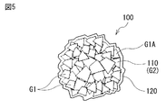
- FIG. 5 schematically illustrates a planar configuration of a positive electrode active material 100 that is a positive electrode active material according to an embodiment of the present technology.
- the positive electrode active material 100 includes a central portion 110 and a coating portion 120 that covers the surface of the central portion 110.
- the central portion 110 is in the form of a plurality of particles and contains the lithium nickel composite oxide described above.
- the coating part 120 contains the above-mentioned boron compound. It should be noted that the covering portion 120 may cover the entire surface of the central portion 110 as shown in FIG. 5, but may cover only a part of the surface of the central portion 110.
- the plurality of primary particles G1 form a secondary particle G2 (central portion 110).
- the boron compound (cover 120) covers the surface of the secondary particles G2, for example. It is considered that a part of the boron compound is solid-dissolved in the primary particles G1.
- the positive electrode active material 100 that is, the central portion 110 (lithium nickel composite oxide) whose surface is coated with the coating portion 120 (boron compound), improves the battery characteristics of the secondary battery 10, as described above. It has the specified structure and physical properties.
- the essential requirements of the positive electrode active material 100 will be described, and then the optional requirements of the positive electrode active material 100 will be described.
- the crystallite size Z (nm) of the (104) plane of the positive electrode active material 100 calculated using the X-ray diffraction (XRD) method and the Scherrer equation is 40.0 nm to 74. It is 0.5 nm.
- the specific surface area A (m 2 /g) of the positive electrode active material 100 measured using the BET specific surface area measurement method satisfies the condition represented by the following formula (2).
- the value of "-0.0160 ⁇ Z” used to calculate the lower limit is rounded to the second decimal place, and "-0.0324 ⁇ ” is used to calculate the upper limit.
- the value of "Z” is a value rounded off to two decimal places.
- the range of the specific surface area A represented by the formula (2) that is, the range of the specific surface area A defined in relation to the crystallite size Z is referred to as “appropriate range”. The theory of deriving the appropriate range of the specific surface area A described here will be described later.
- Z is the crystallite size (nm) of the (104) plane of the positive electrode active material 100.
- A is the specific surface area (m 2 /g) of the positive electrode active material 100.
- FIG. 6 shows an appropriate range for the specific surface area A (crystallite size Z) of the positive electrode active material 100.
- the horizontal axis represents the crystallite size Z (nm), and the vertical axis represents the specific surface area A (m 2 /g).
- the range of possible values of the crystallite size Z and the specific surface area A is, as shown in FIG. 6, two straight lines L (solid line L1 and broken line L2).
- the range Q is defined by.
- the range Q is shaded.
- the element concentration ratio R1 (first element concentration ratio) represented by the following formula (3) is 0.08 to 0.80. It is considered that the element concentration ratio R1 is a parameter that mainly indicates the distribution state of the residual lithium component (Li 2 CO 3 ) on the surface of the positive electrode active material 100.
- R1 I1/I2 (3)
- I1 is the CO 3 concentration (atomic %) calculated based on the C1s spectrum.
- I2 is the Me—O concentration (atomic %) calculated based on the O1s spectrum.
- Me—O is an oxide derived from O that is bound to Li, Ni or M in the formula (1) and has a binding energy of 528 eV or more and 531 eV or less. is there.
- the element concentration ratio R2 (second element concentration ratio) represented by the following formula (4) is 0.60 to 1.50. .. It is considered that the element concentration ratio R2 is a parameter that mainly represents the distribution state of lithium on the surface of the positive electrode active material 100.
- R2 I3/I4 (4)
- R2 is the element concentration ratio.
- I3 is the Li concentration (atomic %) calculated based on the Li1s spectrum.
- I4 is the Ni2p 3/2 spectrum, the Co 2p 3/2 spectrum, and the Mn 2p 1/2 spectrum. And the sum of the Ni concentration (atomic %), the Co concentration (atomic %), the Mn concentration (atomic %), and the Al concentration (atomic %) calculated based on the Al2s spectrum.
- R3 I5/I4 (5)
- R3 is the third element concentration ratio.
- I4 is the Ni concentration (atomic %) and the Co concentration calculated based on the Ni2p3 / 2 spectrum, Co2p3 /2 spectrum, Mn2p1 /2 spectrum and Al2s spectrum.
- I5 is B concentration (Atomic %) calculated based on the B1s spectrum.
- the first condition and the second condition are satisfied because the specific surface area is related to the crystallite size Z. This is because A is optimized. This suppresses the decomposition reaction of the electrolytic solution on the surface of the reactive positive electrode active material 100, and also suppresses the generation of unnecessary gas due to the decomposition reaction of the electrolytic solution. Therefore, it is considered that the discharge capacity is less likely to decrease and gas is less likely to be generated even if charging and discharging are repeated.
- the third condition, the fourth condition and the fifth condition are further satisfied only when the surface state of the positive electrode active material 100 (lithium, boron and This is because the distribution state of each residual lithium component) is optimized. That is, on the surface of the positive electrode active material 100, the surface of the central portion 110 is properly covered by the covering portion 120 while appropriately suppressing the remaining amount of the residual lithium component. This suppresses the generation of gas due to the remaining residual lithium component, facilitates the input and output of lithium ions in the central portion 110, and suppresses the decomposition reaction of the electrolytic solution on the surface of the central portion 110. In this case, it is considered that the decomposition reaction of the electrolytic solution is effectively suppressed even when the secondary battery 10 (positive electrode active material 100) is used (charged/discharged) or stored in a high temperature environment.
- the residual lithium component is an unnecessary component that remains in the positive electrode active material 100 during the manufacturing process of the positive electrode active material 100.
- the remaining lithium components are, for example, lithium carbonate (Li 2 CO 3 ) and lithium hydroxide (LiOH), and become a cause of generation of unnecessary gas during charge/discharge of the secondary battery 10.
- the crystallite size Z is a parameter obtained based on the analysis result of the positive electrode active material 100 using XRD, and as described above, using the Scherrer formula represented by the following formula (6). It is calculated.
- Z K ⁇ /Bcos ⁇ (6)
- K is a Scherrer constant.
- ⁇ is a wavelength (nm) of X-rays.
- B is a half width spread (°) depending on the crystallite size.
- ⁇ is a Bragg angle. That is, it is half the value (°) of the diffraction angle 2 ⁇ .
- a fully automatic multipurpose X-ray diffractometer SmartLab manufactured by Rigaku Corporation is used.
- goniometer SmartLab
- attachment standard ⁇ cradle
- monochromator Bent
- scan mode 2 ⁇ / ⁇
- scan type FT
- X-ray CuK ⁇ -ray
- irradiation intensity 45 kV/200 mA
- incident slit 1/ 2 deg
- light receiving slit 1 1/2 deg
- light receiving slit 2 0.300 mm
- step 0.02.
- K 0.89
- ⁇ (wavelength of CuK ⁇ line) 0.15418 nm
- B half width.
- the specific surface area A (m 2 /g) is the surface area per unit mass of the positive electrode active material 100, and is measured by the BET specific surface area measuring method as described above.
- This BET specific surface area measuring method is a gas for measuring the specific surface area of the positive electrode active material 100 based on the adsorbed amount of the nitrogen molecules by adsorbing nitrogen molecules (N 2 ) on a plurality of particulate positive electrode active materials 100. It is an adsorption method.
- a fully automatic specific surface area measuring device Macsorb (registered trademark) manufactured by Mountech Co., Ltd. is used.
- the mass of the positive electrode active material 100 is 5 g
- the degassing condition is 250° C. ⁇ 40 minutes.
- the positive electrode active material 100 is analyzed using XPS, for example, an X-ray photoelectron spectroscopy analyzer Quantera SXM manufactured by ULVAC-PHI, Inc. is used.
- XPS X-ray photoelectron spectroscopy analyzer Quantera SXM manufactured by ULVAC-PHI, Inc.
- the intensity of a series of peaks is automatically calculated.
- the CO 3 concentration, Me—O concentration, Li concentration, B concentration, Ni concentration, Co concentration, Mn concentration and Al concentration are calculated (converted) based on the measurement result.
- the element concentration ratios R1 to R3 are calculated.
- the residual amount of the residual lithium component is measured by using, for example, the Warder method.
- the Warder method for example, a case of examining the remaining amounts of lithium carbonate (Li 2 CO 3 ) and lithium hydroxide (LiOH) will be described.
- a predetermined amount (Sg) of the positive electrode active material 100 is weighed, and then the positive electrode active material 100 is put into a sample bottle.
- S 10 (g).
- the supernatant is put in an Erlenmeyer flask with a stopper.
- the titration solution (hydrochloric acid (HCl) of concentration M) was used to eliminate the liquid color (red).
- the titrator for example, an automatic titrator COM-1600 manufactured by Hiranuma Sangyo Co., Ltd. is used.
- Residual rate of lithium carbonate (%) [(M ⁇ 2B ⁇ (f/1000) ⁇ 0.5 ⁇ 73.892 ⁇ 5)/S] ⁇ 100 (7)
- S is the weight (g) of the positive electrode active material 100.
- A is the dropping amount (ml) up to the first end point using the phenolphthalein solution.
- B is the phenolphthalein solution. It is the dropping amount (ml) from the first end point to the second end point using the bromophenol blue solution, f is a factor depending on the concentration of the titration solution, and M is the concentration of the titration solution (mol/ l).)
- Residual rate of lithium hydroxide (%) [(M ⁇ (AB) ⁇ (f/1000) ⁇ 23.941 ⁇ 5)/S] ⁇ 100 (8)
- S is the weight (g) of the positive electrode active material 100.
- A is the dropping amount (ml) up to the first end point using the phenolphthalein solution.
- B is the phenolphthalein solution. It is the dropping amount (ml) from the first end point to the second end point using the bromophenol blue solution, f is a factor depending on the concentration of the titration solution, and M is the concentration of the titration solution (mol/ l).)
- FIG. 7 shows a plane configuration corresponding to FIG. 5 in order to explain the analysis range of XPS and the measurement range of the Walder method.
- a part of the positive electrode active material 100 shown in FIG. 5, that is, a part of the central portion 110 (one primary particle G1 (G1A)) and the covering portion 120 are included. Only a part of is expanded.
- the range in which the residual lithium component can be analyzed using XPS is only the range near the surface of the positive electrode active material 100, that is, the relatively narrow range F1.
- the range in which the residual lithium component can be measured using the Walder method is the range from the surface to the inside of the positive electrode active material 100, that is, the relatively wide range F2.
- the positive electrode active material 100 may further satisfy a series of conditions described below.
- the specific surface area A is preferably a 0.53m 2 /g ⁇ 1.25m 2 / g. This is because the decomposition reaction of the electrolytic solution is sufficiently suppressed and the generation of gas is also sufficiently suppressed.
- the particle diameter of the volume-based particle size distribution is not particularly limited.
- the particle diameter D50 is preferably 11.8 ⁇ m to 14.4 ⁇ m.
- the particle diameter D10 is preferably 2.8 ⁇ m to 4.0 ⁇ m, and the particle diameter D90 is preferably 22.7 ⁇ m to 26.3 ⁇ m. This is because generation of a short circuit and peeling of the positive electrode active material layer 21B are suppressed while ensuring the energy density per unit weight.
- SALD-2100 manufactured by Shimadzu Corporation.
- the positive electrode active material layer 21B is easily separated from the positive electrode current collector 21A when the positive electrode active material layer 21B is compression-molded during the production of the positive electrode 21.
- the surface area of the positive electrode active material 100 increases, it becomes necessary to increase the added amount of the conductive agent, the binder and the like, and thus the energy density per unit weight is likely to decrease.
- the positive electrode active material 100 easily penetrates the separator 23, and thus a short circuit easily occurs in the positive electrode 21 and the negative electrode 22.
- pressed density is preferably 3.40g / cm 3 ⁇ 3.60g / cm 3. This is because generation of gas is suppressed while ensuring a high energy density.
- the compression density is less than 3.40 g/cm 3
- the positive electrode active material 100 is less likely to be filled in the positive electrode 21 (positive electrode active material layer 21B), and the energy density per unit weight is likely to decrease.
- the compression density is higher than 3.60 g/cm 3
- the positive electrode active material 100 is easily cracked, so that gas is likely to be generated due to the formation of a reactive new surface.
- This compression density is a so-called press density (volume density), and is measured by the procedure described below, for example.
- the positive electrode active material 100 and cellulose are put into a mortar, and then the positive electrode active material 100 and cellulose are uniformly mixed using the mortar to obtain a mixed sample.
- the mixing ratio weight ratio
- the thickness (cm) of the mixed sample is measured.
- the volume-based particle size distribution of the positive electrode active material 100 has two or more peaks. This is because the positive electrode active material 100 is more easily filled in the positive electrode 21 (positive electrode active material layer 21B), as compared with the case where the volume-based particle size distribution has only one peak. Further, since the number of contact points between the positive electrode active materials 100 increases, the force during compression molding is easily dispersed during the production of the positive electrode 21 (during compression molding of the positive electrode active material layer 21B). Is less likely to break. This increases the energy density per unit weight.
- the volume-based particle size distribution can be measured using, for example, the above-mentioned laser diffraction type particle size distribution measuring device.
- FIG. 8 shows an example of the volume-based particle size distribution.
- the horizontal axis represents the particle diameter ( ⁇ m) and the vertical axis represents the relative particle amount (%).
- the volume-based particle size distribution is Has a first peak P1 (first peak) in a range Q1 of 3 ⁇ m to 7 ⁇ m, and a second peak P2 (second peak) in a range Q2 of particle diameter of 14 ⁇ m to 30 ⁇ m. ) are preferred.
- the positive electrode active material 100 When the particle diameters (D10, D50, D90) of the volume-based particle size distribution satisfy the above-mentioned conditions, the positive electrode active material 100 easily forms a close-packed structure in the positive electrode 21 (positive electrode active material layer 21B). Because it will be. In FIG. 8, the ranges Q1 and Q2 are shaded.
- compressed density is the 3.45g / cm 3 ⁇ 3.70g / cm 3 It is preferable. This is because generation of gas is suppressed while ensuring high energy density for the same reason as when the condition relating to the particle diameter of the particle size distribution on the volume basis is satisfied.
- the open circuit voltage (that is, battery voltage) in a fully charged state per pair of electrodes (positive electrode 21 and negative electrode 22) is not particularly limited and may be less than 4.20V, but may be 4.20V or more.
- the battery voltage is preferably 4.25V or more, more preferably 4.25V to 6.00V. This is because, compared with the case where the battery voltage is 4.20 V, the amount of lithium released per unit mass increases even when the same type of positive electrode active material is used. In this case, in order to obtain a high energy density, the amount of the positive electrode active material and the amount of the negative electrode active material are adjusted to each other according to the amount of lithium released per unit mass.
- a source of lithium lithium compound
- a source of nickel nickel compound
- optionally a source of additional metal element M shown in Formula (1)
- additional compound additional metal element
- the lithium compound may be, for example, an inorganic compound or an organic compound.
- the type of this lithium compound may be only one type, or may be two or more types. What has been described here regarding the lithium compound is the same as regarding the nickel compound and the additional compound.
- lithium compounds are as follows.
- Examples of the lithium compound that is an inorganic compound include lithium hydroxide, lithium carbonate, lithium nitrate, lithium fluoride, lithium chloride, lithium bromide, lithium iodide, lithium chlorate, lithium perchlorate, lithium bromate, and iodine.
- Lithium oxide, lithium oxide, lithium peroxide, lithium sulfide, lithium hydrogen sulfide, lithium sulfate, lithium hydrogen sulfate, lithium nitride, lithium azide, lithium nitrite, lithium phosphate, lithium dihydrogen phosphate and lithium hydrogen carbonate etc. is there.
- the lithium compound which is an organic compound is, for example, methyllithium, vinyllithium, isopropyllithium, butyllithium, phenyllithium, lithium oxalate and lithium acetate.
- aqueous solvent such as pure water is used to dissolve the nickel compound and the additional compound, and then a coprecipitate (nickel composite coprecipitated hydroxide) is obtained by a coprecipitation method.
- the mixing ratio of the nickel compound and the additional compound is adjusted according to the composition of the finally obtained central portion 110 (lithium nickel composite oxide).
- the alkaline compound for coprecipitation for example, any one kind or two or more kinds of hydroxides such as sodium hydroxide (NaOH) and ammonium hydroxide (NH 4 OH) is used.
- the nickel composite coprecipitated hydroxide is washed with water, and then the nickel composite coprecipitated hydroxide is dried.
- the nickel is formed by coprecipitation method.
- the particle size of the secondary particles G2 of the nickel composite coprecipitated hydroxide is adjusted by adjusting the reaction time during the coprecipitation.
- a precursor is obtained by mixing a lithium compound, a nickel composite coprecipitated hydroxide, and an additional compound as needed.
- the mixing ratio of the nickel compound, the nickel composite coprecipitated hydroxide and the additional compound is adjusted according to the composition of the finally obtained central portion 110 (lithium nickel composite oxide).
- the specific surface area A can be controlled by adjusting the particle size of the secondary particles G2 of the nickel composite coprecipitated hydroxide.
- a precursor containing a lithium compound and a nickel composite coprecipitated hydroxide and optionally an additional compound is calcined.
- a compound (lithium nickel composite oxide) containing lithium, nickel, and an additional metal element as constituent elements is formed, so that the central portion 110 containing the lithium nickel composite oxide is obtained.
- the lithium-nickel composite oxide obtained here most of the plurality of primary particles G1 are aggregated, and therefore most of the plurality of primary particles G1 form the secondary particles G2.
- the conditions such as firing temperature are not particularly limited and can be set arbitrarily. Above all, the firing temperature is preferably 650°C to 850°C. This is because a lithium nickel composite oxide having a stable composition can be easily manufactured with good reproducibility.
- the firing temperature when the firing temperature is lower than 650° C., the lithium compound becomes difficult to diffuse and the R3m layered rock salt type crystal structure is not easily formed sufficiently.
- the firing temperature when the firing temperature is higher than 850° C., lithium deficiency due to the volatilization of the lithium compound is likely to occur in the crystal structure of the lithium nickel composite oxide, and the lithium deficiency site (empty site) is generated. Due to the incorporation of other atoms, the composition of the lithium-nickel composite oxide tends to have a non-stoichiometric composition.
- the other atom is, for example, nickel (Ni 2+ ) having an ionic radius almost equal to that of lithium (Li + ).
- the mixed area of nickel becomes the cubic rock salt phase (rock salt domain).
- This rock salt domain is electrochemically inactive, and nickel mixed into the lithium site has a property of easily inhibiting solid-phase diffusion of a lithium single phase. Therefore, the deterioration of the battery characteristics (including the electric resistance characteristics) of the secondary battery 10 is easily induced.
- the precursor is preferably fired in an oxygen atmosphere in order to prevent unnecessary reduction reaction from occurring during firing of the precursor.
- This reduction reaction is, for example, a reduction reaction of nickel (Ni 3+ ⁇ Ni 2+ ).
- the specific surface area A and the crystallite size Z can be controlled by adjusting the firing temperature.
- the central portion 110 (lithium nickel composite oxide) is washed with an aqueous solvent such as pure water.
- the central portion 110 may be mechanically washed using a stirrer or the like, if necessary.
- Conditions such as the cleaning time are not particularly limited and can be set arbitrarily.
- the element concentration ratios R1 and R2 can be controlled by adjusting the washing time, that is, the remaining amount of the remaining lithium component can be controlled.
- the element concentration ratio R3 can be controlled by adjusting the addition amount of the boron compound, that is, the coating state of the surface of the lithium nickel composite oxide with the boron compound can be controlled. is there. Moreover, the element concentration ratios R1 and R2 can be controlled by adjusting the firing temperature.
- Secondary battery manufacturing method When manufacturing the secondary battery 10, for example, as described below, a manufacturing process of the positive electrode 21, a manufacturing process of the negative electrode 22, a preparing process of the electrolytic solution, and an assembling process of the secondary battery 10 are performed in this order.
- the positive electrode active material 100, the binder, and the conductive agent are mixed to form a positive electrode mixture.
- the positive electrode mixture slurry is prepared by dispersing the positive electrode mixture in a dispersion solvent.
- the kind of the solvent for dispersion is not particularly limited, but is, for example, an organic solvent such as N-methyl-2-pyrrolidone.
- the positive electrode active material layer 21B is formed by applying the positive electrode mixture slurry on both surfaces of the positive electrode current collector 21A (positive electrode active material layer forming portion 21M).
- the positive electrode active material layer 21B is compression-molded using a roll press. Thereby, the positive electrode active material layers 21B are formed on both surfaces of the positive electrode current collector 21A, so that the positive electrode 21 is manufactured.
- a negative electrode active material, a binder, and a conductive agent are mixed to obtain a negative electrode mixture.
- a negative electrode mixture slurry in paste form is prepared by dispersing the negative electrode mixture in a solvent for dispersion.
- the type of solvent for dispersion is not particularly limited, but examples thereof include organic solvents such as N-methyl-2-pyrrolidone and methyl ethyl ketone.
- the negative electrode active material layer 22B is formed by applying the negative electrode mixture slurry on both surfaces of the negative electrode current collector 22A (negative electrode active material layer forming portion 22M).
- the negative electrode active material layer 22B is compression-molded using a roll press. As a result, the negative electrode active material layers 22B are formed on both surfaces of the negative electrode current collector 22A, so that the negative electrode 22 is manufactured.
- a plurality of positive electrodes 21 and a plurality of negative electrodes 22 are alternately laminated with the separators 23 in between to form a laminated body. Then, the plurality of positive electrode current collector exposed portions 21N are bonded to each other, and the positive electrode lead 11 is bonded to the plurality of bonded positive electrode current collector exposed portions 21N. Further, the plurality of negative electrode current collector exposed portions 22N are bonded to each other, and the negative electrode lead 12 is bonded to the plurality of bonded negative electrode current collector exposed portions 22N.
- the joining method of each of the positive electrode lead 11 and the negative electrode lead 12 is not particularly limited, but is, for example, ultrasonic welding, resistance welding or soldering.
- the first member 30A and the second member 30B are superposed on each other via the laminated body. Then, the outer peripheral edge portions of the remaining three sides of each of the first member 30A and the second member 30B except for the outer peripheral edge portion of one side are brought into close contact with each other, so that the inside of the bag-shaped exterior member 30 is Store the stack.
- the method of bringing the first member 30A and the second member 30B into close contact with each other is not particularly limited, and for example, a heat fusion method may be used or an adhesive may be used.
- the adhesion film 13 is inserted between the exterior member 30 (the first member 30A and the second member 30B) and the positive electrode lead 11, and the adhesion film 13 is provided between the exterior member 30 and the negative electrode lead 12. Insert.
- the adhesion film 13 may be attached to each of the positive electrode lead 11 and the negative electrode lead 12 in advance.
- the laminate is impregnated with the electrolytic solution, so that the electrode body 20 is formed.
- the secondary battery 10 is assembled.
- the laminated film type secondary battery 10 is completed.
- the positive electrode 21 includes the positive electrode active material 100 including the central portion 110 (lithium nickel composite oxide) and the coating portion 120 (boron compound), and regarding the configuration and the physical properties of the positive electrode active material 100.
- the above five conditions are simultaneously satisfied. In this case, as described above, while the input and output of lithium ions are secured, the decomposition reaction of the electrolytic solution is suppressed and the generation of gas is also suppressed. Therefore, even if charging and discharging are repeated, the discharge capacity is less likely to decrease and the secondary battery 10 is less likely to swell, and thus excellent battery characteristics can be obtained.
- the specific surface area A of the positive electrode active material 100 is as long as 0.53m 2 /g ⁇ 1.25m 2 / g, the generation of gas is also sufficiently suppressed with the decomposition reaction of the electrolytic solution is sufficiently suppressed , A higher effect can be obtained.
- the particle diameter D50 of the volume-based particle size distribution of the positive electrode active material 100 is 11.8 ⁇ m to 14.4 ⁇ m, the occurrence of short circuit and peeling of the positive electrode active material layer 21B while ensuring the energy density per unit weight. Since it is suppressed, a higher effect can be obtained.
- the particle diameter D10 is 2.8 ⁇ m to 4.0 ⁇ m and the particle diameter D90 is 22.7 ⁇ m to 26.3 ⁇ m, a higher effect can be obtained.
- the pressed density of the positive electrode active material 100 is 3.40g / cm 3 ⁇ 3.60g / cm 3, since while a high energy density is secured generation of gas is suppressed, a higher effect is obtainable it can.
- the volume-based particle size distribution of the positive electrode active material 100 has two or more peaks, the positive electrode active material 100 is easily filled in the positive electrode 21 (positive electrode active material layer 21B) and is less likely to be broken. As a result, the energy density per unit weight increases and the decomposition reaction of the electrolytic solution and the generation of gas are suppressed, so that a higher effect can be obtained.
- the volume-based particle size distribution has two peaks (a peak in the range of the particle size of 3 ⁇ m to 7 ⁇ m and a peak in the range of the particle size of 14 ⁇ m to 30 ⁇ m)
- the positive electrode active Since the substance 100 easily forms the close-packed structure, a higher effect can be obtained.
- the pressed density of the positive electrode active material 100 is 3.45g / cm 3 ⁇ 3.70g / cm 3, since while a high energy density is secured generation of gas is suppressed, a higher effect is obtainable it can.
- the positive electrode 21, the negative electrode 22 and the electrolytic solution are housed inside the film-shaped exterior member 30, a laminate film type secondary battery 10 using the exterior member 30 that is easily deformed due to a change in internal pressure.
- the generation of gas is suppressed as described above. Therefore, even when the laminated film type secondary battery 10 in which swelling is likely to occur is used, the swelling of the secondary battery 10 can be effectively suppressed.
- the positive electrode active material 100 used in the secondary battery 10 includes a central portion 110 (lithium nickel composite oxide) and a coating portion 120 (boron compound).
- a central portion 110 lithium nickel composite oxide
- a coating portion 120 boron compound
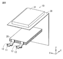
- FIG. 1 As shown in FIG. 1, two exterior members 30 (first member 30A and second member 30B) were used. However, as shown in FIG. 9 corresponding to FIG. 1, one foldable exterior member 30 may be used instead of the two exterior members 30.
- the single exterior member 30 has, for example, a configuration in which one side of the first member 30A and one side of the second member 30B facing the one side of the first member 30A are connected to each other. Even in this case, since the electrode body 20 is housed inside the exterior member 30, the same effect can be obtained.
- Electrode body 20 includes an electrolyte layer, and in the electrode body 20, a plurality of positive electrodes 21 and a plurality of negative electrodes 22 are alternately laminated with the separator 23 and the electrolyte layer interposed therebetween.
- the electrolyte layer is interposed between the positive electrode 21 and the separator 23 and also between the negative electrode 22 and the separator 23.
- the electrolyte layer contains an electrolytic solution and a polymeric material that holds the electrolytic solution, and the polymeric material is swollen with the electrolytic solution.
- the mixing ratio of the electrolytic solution and the polymer material can be set arbitrarily.
- the polymer material may be, for example, a homopolymer such as polyvinylidene fluoride, a copolymer such as a copolymer of vinylidene fluoride and hexafluoropropylene, or both. Also in this case, since lithium ions can move between the positive electrode 21 and the negative electrode 22 through the electrolyte layer, the same effect can be obtained.
- the separator 23 may include, for example, a base material layer and a polymer layer provided on the base material layer.
- the polymer layer may be provided on only one surface of the base material layer, or may be provided on both surfaces of the base material layer.
- the base material layer is, for example, the above-mentioned porous membrane.
- the polymer layer contains a polymer material such as polyvinylidene fluoride. This is because it has excellent physical strength and is electrochemically stable.
- the polymer layer may include a plurality of inorganic particles, for example. This is because, when the temperature of the secondary battery 10 rises due to heat generation or the like, the plurality of inorganic particles radiate heat to improve the safety of the secondary battery 10.
- the type of inorganic particles is not particularly limited, but examples thereof include insulating particles such as aluminum oxide and aluminum nitride.
- the separator 23 including the base material layer and the polymer layer is formed, for example, by applying a precursor solution containing a polymer material and an organic solvent to both surfaces of the base material layer.
- the separator 23 includes a polymer layer
- the electrolyte layer may be omitted. This is because when the polymer layer is impregnated with the electrolytic solution, the polymer layer swollen with the electrolytic solution performs the same function as the electrolyte layer.
- the configuration of the electrode body 20 is not particularly limited.
- the electrode body 20 may be, for example, a foldable type in which a single positive electrode 21 and a single negative electrode 22 are folded with a separator 23 in between, or a single positive electrode 21 and a single negative electrode 22.
- a winding type in which the separator 23 is wound may be used. Also in these cases, since the positive electrode 21 and the negative electrode 22 can be charged and discharged, the same effect can be obtained.
- Secondary batteries are used for machines, devices, appliances, devices and systems (aggregates of multiple devices) that can be used as a power source for driving and a power storage source for power storage. If there is, it is not particularly limited.
- the secondary battery used as a power source may be a main power source or an auxiliary power source.
- the main power source is a power source that is preferentially used regardless of the presence or absence of another power source.
- the auxiliary power source may be a power source used instead of the main power source, or a power source that can be switched from the main power source as needed.
- the type of main power source is not limited to the secondary battery.
- the use of the secondary battery is as follows, for example.
- Electronic devices including portable electronic devices
- portable electronic devices such as video cameras, digital still cameras, mobile phones, notebook computers, cordless phones, headphone stereos, portable radios, portable televisions and portable information terminals.
- It is a portable household appliance such as an electric shaver.
- It is a storage device such as a backup power supply and a memory card.
- Electric tools such as electric drills and electric saws.
- This is a battery pack that can be mounted on a laptop computer as a detachable power source.
- Medical electronic devices such as pacemakers and hearing aids.
- Electric vehicles such as electric vehicles (including hybrid vehicles).
- It is a power storage system such as a household battery system that stores power in case of an emergency.
- the application of the secondary battery may be other than the above-mentioned applications.
- the nickel-cobalt composite coprecipitated hydroxide was washed with an aqueous solvent (pure water), and then the nickel-cobalt composite coprecipitated hydroxide was dried.
- lithium compound lithium hydroxide monohydrate (LiOH.H 2 O)
- additional compound aluminum hydroxide (Al(OH) 3 )
- the mixing ratio with the additional compound was adjusted.
- the precursor was fired in an oxygen atmosphere.
- the firing temperature (° C.) in the first firing step is as shown in Table 1.
- a plurality of particulate lithium nickel composite oxides (LiNi 0.82 Co 0.14 Al 0.04 O 2 ) were synthesized, so that the central portion 110 containing the lithium nickel composite oxide was obtained.
- an aqueous solvent pure water
- the coating step (second firing step), a mixture was obtained by mixing the central portion 110 and a boron compound (boric acid (H 3 BO 3 ). Addition amount of boric acid (% by mass), that is, the central portion. The ratio of the weight of boric acid to the weight of 110 is as shown in Table 1. After that, the mixture was fired in an oxygen atmosphere, and the firing temperature (°C) of the second firing step was shown in Table 1. As a result, the positive electrode active material 100 was obtained because the surface of the central portion 110 (lithium nickel composite oxide) was covered with the coating portion 120 (boron compound), as shown in FIG.
- a boron compound boron compound
- another positive electrode active material 100 was also obtained by synthesizing a plurality of other particulate lithium nickel composite oxides.
- Manganese hydroxide (Mn(OH) 2 ) was used instead of aluminum hydroxide as an additional compound, and the molar ratio of lithium, nickel, cobalt, and manganese was adjusted to replace LiNi 0.82 Co 0.14 Al 0.04 O 2 .
- Another positive electrode active material 100 was obtained by the same procedure except that LiNi 0.84 Co 0.08 Mn 0.08 O 2 was synthesized.
- the crystallite size Z (nm) was calculated using the Scherrer formula based on the analysis result (peak of the (104) plane). The results shown in Table 3 were obtained. Further, when the specific surface area A (m 2 /g) of the positive electrode active material 100 was measured using the BET specific surface area measuring method, the results shown in Table 2 and Table 3 were obtained. The “appropriate range (m 2 /g)” shown in Tables 2 and 3 indicates the proper range of the specific surface area A derived from the equation (2).
- the numerical value on the left side is a value calculated by ⁇ 0.0160 ⁇ Z+1.72 and the numerical value on the right side is Is a value calculated by ⁇ 0.0324 ⁇ Z+2.94.
- the compressed density of the positive electrode active material 100 was measured, the compressed density was 3.60 g/cm 3 .
- the particle diameter D50 was 13.2 ⁇ m
- the particle diameter D10 was 3.4 ⁇ m
- the particle diameter D90 was 24.5 ⁇ m.
- the volume-based particle size distribution of the positive electrode active material 100 was measured, as shown in FIG. 8, two peaks P, that is, a peak P1 corresponding to the small particle size and a peak P2 corresponding to the large particle size, were obtained. was gotten.
- the particle diameter corresponding to the first peak P1 (particle diameter at the peak top) is 4.4 ⁇ m
- the particle diameter corresponding to the second peak P2 is 19.1 ⁇ m. there were.
- the positive electrode active material layer 21B was formed by drying. Finally, the positive electrode active material layer 21B was compression-molded using a roll press.
- the negative electrode active material graphite
- 10 parts by mass of the binder polyvinylidene fluoride
- the negative electrode mixture was put into an organic solvent (N-methyl-2-pyrrolidone), and the organic solvent was stirred to prepare a paste-like negative electrode mixture slurry.
- the negative electrode active material layer 22B was formed by drying. Finally, the negative electrode active material layer 22B was compression-molded using a roll press.
- the electrolyte salt lithium hexafluorophosphate
- the solvent ethylene carbonate and ethyl methyl carbonate
- a moisture-proof aluminum laminate film laminated in this order was used.
- the 1st member 30A and the 2nd member 30B after arranging a layered product between the 1st member 30A and the 2nd member 30B, the 1st member 30A (heat-bonding resin layer) and the 2nd member 30B (heat-bonding) are used using a heat-bonding method.
- the outer peripheral edge portions of the three sides of each of the resin layers) were brought into close contact with each other, whereby the laminated body was housed inside the bag-shaped exterior member 30.
- the exterior member 30 was sealed by using the heat fusion method.
- the adhesion film 13 was inserted between the film 12 and the film 12.
- the laminate was impregnated with the electrolytic solution, so that the electrode body 20 was formed.
- the electrode body 20 was housed inside the exterior member 30 while the positive electrode lead 11 and the negative electrode lead 12 were led out from the inside of the exterior member 30.
- the laminated film type secondary battery 10 shown in FIGS. 1 to 4 was completed.
- the initial capacities shown in Tables 2 and 3 are values normalized with the initial capacities of Experimental Example 1-1 as 100.
- constant current charging was performed with a current of 0.1 C until the battery voltage reached 4.2 V, and then constant voltage charging was performed with a battery voltage of 4.2 V until the current reached 0.005 C.
- constant current discharge was performed with a current of 0.1 C until the battery voltage reached 2.5 V.
- 0.1 C is a current value at which the battery capacity (theoretical capacity) is completely discharged in 10 hours
- 0.005 C is a current value at which the battery capacity is completely discharged in 200 hours.
- the discharge capacity (second cycle discharge capacity) was measured by performing cycle charge/discharge.
- the discharge capacity (the discharge capacity at the 102nd cycle) was measured by charging and discharging the secondary battery 10 for 100 cycles in the same environment.
- the capacity retention ratio (%) (discharge capacity at 102nd cycle/discharge capacity at second cycle) ⁇ 100 was calculated.
- constant current charging was performed with a current of 1.0 C until the battery voltage reached 4.2 V, and then constant voltage charging was performed with the battery voltage of 4.2 V until the total charging time reached 2.5 hours.
- constant current discharge was performed with a current of 5.0 C until the battery voltage reached 2.5 V.
- 1.0 C is a current value at which the battery capacity is completely discharged in 1 hour
- 5.0 C is a current value at which the battery capacity is completely discharged in 0.2 hour.
- the laminate cell for evaluation is charged (constant current charge) until the voltage reaches 4.2 V with a current of 0.1 C, and the total charging time reaches 2.5 hours at the voltage of 4.2 V.
- the volume of the evaluation laminated cell (volume before storage: cm 3 ) was measured using the Archimedes method.
- This gas generation amount is a so-called gas generation amount per unit weight of the positive electrode active material 100, and therefore is an index showing the physical properties (gas generation characteristics) of the positive electrode active material 100, and by extension, the swelling characteristic of the secondary battery 10. Is a parameter for predicting.
- the capacity retention rate (%) is examined by changing each of the crystallite size Z and the specific surface area A to obtain the crystal.
- the correspondence between the child size Z and the specific surface area A and the capacity retention rate was obtained.
- the crystallite size Z 40.0nm ⁇ 80.0nm
- specific surface area A 0.40m 2 /g ⁇ 1.80m 2 / g .
- the specific surface area A (m 2 /g) was examined while changing the cleaning time in the water washing step to obtain the correspondence relationship between the cleaning time and the specific surface area A.
- the specific surface area A 0.40m 2 /g ⁇ 1.80m 2 / g .
- an approximate straight line was obtained by performing a linear approximation using these values.
- the gas generation amount becomes 6 cm 3 /g using an approximate straight line.
- the specific surface area A was specified.
- the specific surface area A when the gas generation amount was 6 cm 3 /g was specified for each crystallite size Z by the same procedure.
- the crystallite size Z was 40.0 nm to 80.0 nm.
- the range Q is a range of the crystallite size Z and a range of the specific surface area A in which the capacity retention rate is 85 or more and the specific surface area A becomes the upper limit value due to the variation of the cleaning time in each crystallite size Z.
- the range is theoretically derived by using the multiple regression analysis.
- the amount of gas generated due to the positive electrode active material 100 was suppressed, so that the initial capacity was secured and the gas generation amount was suppressed, while maintaining a high capacity retention rate. was gotten.
- the range of the specific surface area A shown in the formula (2) that is, the range of the specific surface area A defined in relation to the crystallite size Z (range Q shown in FIG. 6) is the It was confirmed that the amount was within the proper range that contributes to the suppression of the gas generation amount.
- the specific surface area A is 0.53m 2 /g ⁇ 1.25m 2 / g, while the gas generation amount is suppressed sufficiently, sufficiently high cell The capacity was obtained and a sufficiently high capacity retention rate was also obtained.
- the residual ratio of lithium carbonate was suppressed to be substantially equal to or less than that when the five conditions were not satisfied at the same time, and the lithium hydroxide The residual rate was suppressed to the same level.
- the analyzable range (range F1) of the residual lithium component using XPS is relatively narrow, whereas the residual lithium component can be measured using the Walder method.
- the range (range F2) becomes relatively wide. Therefore, even if the residual amount of the residual lithium component such as lithium carbonate measured by the Walder method is low, the gas generation amount may increase. This is because even if the remaining amount of the residual lithium component is reduced by ensuring the washing time in the washing step, if the firing temperature is increased in the coating step (second firing step), the positive electrode active material 100 (lithium nickel composite It is considered that this is because lithium is eluted from the inside of the (oxide) and new lithium carbonate is formed near the outermost surface of the positive electrode active material 100.
- range F2 When the Walder method having a wide measurable range (range F2) is used, the amount of lithium carbonate near the outermost surface of the positive electrode active material 100 cannot be measured.
- range F1 when XPS having a narrow measurable range (range F1) is used, the amount of the gas generation source (eluting lithium) near the outermost surface of the positive electrode active material 100 can be quantified. Therefore, when the amount of the gas generation source near the outermost surface of the positive electrode active material 100 is large, it is considered that the amount of gas generation in the secondary battery 10 has increased.
- Example 4 As shown in Table 4, a secondary battery was prepared by the same procedure except that the particle diameters D10, D50, D90 ( ⁇ m) of the volume-based particle size distribution regarding the positive electrode active material 100 were changed, and the battery characteristics were also obtained. (Cycle characteristics) was evaluated. In this case, as shown in Table 4, the particle diameters D10, D50, and D90 were changed by changing the mixing ratio (weight ratio) of the small particle diameter particles and the large particle diameter particles. In response to this, the compression density (g/cm 3 ) of the positive electrode active material 100 was also changed.
- Example 3-8 As shown in Table 5, a secondary battery was prepared by the same procedure except that the particle size ( ⁇ m) of the peak P1 and the particle size ( ⁇ m) of the peak P2 in the volume-based particle size distribution were changed. The battery characteristics (cycle characteristics) were evaluated. In this case, as shown in Table 5, by mixing the small particle size particles and the large particle size particles at a predetermined mixing ratio (weight ratio), the positive electrode active material having two peaks P (P1, P2) is obtained. Material 100 was obtained. The particle diameter D50 ( ⁇ m) of each of the small particle diameter and the large particle diameter is as shown in Table 5. In response to this, the compression density (g/cm 3 ) of the positive electrode active material 100 was also changed.
- the positive electrode active material 100 including the central portion 110 (lithium-nickel composite oxide) and the coating portion 120 (boron compound) is used, five conditions regarding the constitution and physical properties of the positive electrode active material 100 are simultaneously satisfied. When satisfied, the positive electrode active material 100 provided excellent gas generation characteristics. Therefore, in the secondary battery 10 using the positive electrode active material 100, all of the initial capacity characteristics, the cycle characteristics, and the swollenness characteristics (gas generation characteristics) were good, and excellent battery characteristics were obtained.
- the secondary battery of the present invention is a laminate film type secondary battery has been described, but the type of the secondary battery of the present invention is not particularly limited. Specifically, the secondary battery of the present invention may be another type of secondary battery such as a cylindrical type, a square type, or a coin type.
Landscapes
- Chemical & Material Sciences (AREA)
- General Chemical & Material Sciences (AREA)
- Chemical Kinetics & Catalysis (AREA)
- Electrochemistry (AREA)
- Engineering & Computer Science (AREA)
- Inorganic Chemistry (AREA)
- Composite Materials (AREA)
- Manufacturing & Machinery (AREA)
- Materials Engineering (AREA)
- General Physics & Mathematics (AREA)
- Condensed Matter Physics & Semiconductors (AREA)
- Physics & Mathematics (AREA)
- Battery Electrode And Active Subsutance (AREA)
- Secondary Cells (AREA)
- Sealing Battery Cases Or Jackets (AREA)
Abstract
L'invention concerne un matériau actif d'électrode positive pour une batterie secondaire, le matériau actif d'électrode positive comprenant : une partie centrale contenant un oxyde composite de lithium-nickel de type sel gemme stratifié ; et une partie gaine recouvrant la surface de la partie centrale et contenant un composé de bore. La taille de cristallite du plan (104) est de 40,0 à 74,5 nm telle que calculée à l'aide de la diffraction des rayons X et de l'équation de Scherrer. La surface spécifique satisfait la condition représentée par -0,0160 × Z +1,72 ≤ A ≤ -0,0324 × Z +2,94 (Z est la taille de cristallite (nm) et A est une surface spécifique (m2/g) telle que mesurée à l'aide du procédé de mesure de surface spécifique BET. Le rapport de concentration d'un premier élément est de 0,08 à 0,80, le rapport de concentration d'un deuxième élément est de 0,60 à 1,50, et le rapport de concentration d'un troisième élément est de 0,15 à 0,90 tel que calculé sur la base de spectres C1s, de spectres O1s, et analogues mesurés à l'aide de la spectroscopie photoélectronique à rayons X.
Priority Applications (3)
| Application Number | Priority Date | Filing Date | Title |
|---|---|---|---|
| JP2020571120A JP7078141B2 (ja) | 2019-02-06 | 2020-01-29 | 二次電池用正極活物質および二次電池 |
| CN202080012652.0A CN113474919B (zh) | 2019-02-06 | 2020-01-29 | 二次电池用正极活性物质及二次电池 |
| US17/393,502 US12211993B2 (en) | 2019-02-06 | 2021-08-04 | Positive electrode active material for secondary battery, and secondary battery |
Applications Claiming Priority (2)
| Application Number | Priority Date | Filing Date | Title |
|---|---|---|---|
| JP2019-019689 | 2019-02-06 | ||
| JP2019019689 | 2019-02-06 |
Related Child Applications (1)
| Application Number | Title | Priority Date | Filing Date |
|---|---|---|---|
| US17/393,502 Continuation US12211993B2 (en) | 2019-02-06 | 2021-08-04 | Positive electrode active material for secondary battery, and secondary battery |
Publications (1)
| Publication Number | Publication Date |
|---|---|
| WO2020162277A1 true WO2020162277A1 (fr) | 2020-08-13 |
Family
ID=71947618
Family Applications (1)
| Application Number | Title | Priority Date | Filing Date |
|---|---|---|---|
| PCT/JP2020/003095 Ceased WO2020162277A1 (fr) | 2019-02-06 | 2020-01-29 | Matériau actif d'électrode positive pour batterie secondaire et batterie secondaire |
Country Status (4)
| Country | Link |
|---|---|
| US (1) | US12211993B2 (fr) |
| JP (1) | JP7078141B2 (fr) |
| CN (1) | CN113474919B (fr) |
| WO (1) | WO2020162277A1 (fr) |
Cited By (12)
| Publication number | Priority date | Publication date | Assignee | Title |
|---|---|---|---|---|
| WO2021192403A1 (fr) * | 2020-03-27 | 2021-09-30 | 株式会社村田製作所 | Batterie rechargeable |
| CN114792785A (zh) * | 2021-01-25 | 2022-07-26 | 泰星能源解决方案有限公司 | 非水电解质二次电池 |
| JP2022111526A (ja) * | 2021-01-20 | 2022-08-01 | Fdk株式会社 | ラミネート型蓄電素子 |
| JP2023513558A (ja) * | 2020-10-31 | 2023-03-31 | 寧徳時代新能源科技股▲分▼有限公司 | 正極活物質、及びその製造方法、二次電池、電池モジュール、バッテリパック及び装置 |
| JP2023552355A (ja) * | 2021-01-11 | 2023-12-15 | エルジー・ケム・リミテッド | 正極活物質の製造方法および正極活物質 |
| JP2024066001A (ja) * | 2022-10-31 | 2024-05-15 | 住友金属鉱山株式会社 | リチウムイオン二次電池用正極活物質の製造方法 |
| JP2024066003A (ja) * | 2022-10-31 | 2024-05-15 | 住友金属鉱山株式会社 | リチウムイオン二次電池用正極活物質の製造方法 |
| JP2024528157A (ja) * | 2021-08-02 | 2024-07-26 | ユミコア | 充電式リチウムイオン電池用正極活物質 |
| JP2024532312A (ja) * | 2021-08-24 | 2024-09-05 | エルジー・ケム・リミテッド | 正極活物質および正極活物質の製造方法 |
| JP2024138844A (ja) * | 2023-03-27 | 2024-10-09 | プライムプラネットエナジー&ソリューションズ株式会社 | 正極合剤のスラリーの製造方法及び正極の製造方法 |
| JP2024542708A (ja) * | 2022-07-06 | 2024-11-15 | エルジー エナジー ソリューション リミテッド | 再生正極活物質、その再生方法及びそれを含む二次電池 |
| JP2025508507A (ja) * | 2022-03-07 | 2025-03-26 | ビーワイディー カンパニー リミテッド | リン酸鉄リチウム正極活物質、その調製方法、およびリチウム・イオン電池 |
Families Citing this family (6)
| Publication number | Priority date | Publication date | Assignee | Title |
|---|---|---|---|---|
| JP7463327B2 (ja) * | 2021-10-19 | 2024-04-08 | プライムプラネットエナジー&ソリューションズ株式会社 | 二次電池 |
| EP4231374A1 (fr) * | 2022-02-22 | 2023-08-23 | Lilium eAircraft GmbH | Ensemble électrode avec couche d'étalement thermique, cellule de batterie et batterie utilisant lesdits ensembles électrodes |
| JP2024065998A (ja) * | 2022-10-31 | 2024-05-15 | 住友金属鉱山株式会社 | リチウムイオン二次電池用正極活物質の製造方法 |
| JP2024065999A (ja) * | 2022-10-31 | 2024-05-15 | 住友金属鉱山株式会社 | リチウムイオン二次電池用正極活物質、リチウムイオン二次電池 |
| JP7826902B2 (ja) * | 2022-10-31 | 2026-03-10 | 住友金属鉱山株式会社 | リチウムイオン二次電池用正極活物質、リチウムイオン二次電池 |
| JP2024065997A (ja) * | 2022-10-31 | 2024-05-15 | 住友金属鉱山株式会社 | リチウムイオン二次電池用正極活物質、リチウムイオン二次電池 |
Citations (3)
| Publication number | Priority date | Publication date | Assignee | Title |
|---|---|---|---|---|
| JP2004253174A (ja) * | 2003-02-18 | 2004-09-09 | Nichia Chem Ind Ltd | 非水電解液二次電池用正極活物質 |
| JP2004335278A (ja) * | 2003-05-08 | 2004-11-25 | Nichia Chem Ind Ltd | 非水電解液二次電池用正極活物質 |
| JP2018073686A (ja) * | 2016-10-31 | 2018-05-10 | 住友化学株式会社 | リチウム二次電池用正極活物質前駆体、リチウム二次電池用正極活物質の製造方法 |
Family Cites Families (10)
| Publication number | Priority date | Publication date | Assignee | Title |
|---|---|---|---|---|
| JP2002124261A (ja) * | 1999-11-29 | 2002-04-26 | Mitsui Chemicals Inc | リチウム二次電池用正極活物質および電池 |
| JP5234394B2 (ja) * | 2007-09-21 | 2013-07-10 | 住友電気工業株式会社 | リチウム電池 |
| EP2922121B1 (fr) * | 2012-11-13 | 2019-05-15 | Toda Kogyo Corp. | Poudre de particules de manganate de lithium destinée à être utilisée dans une batterie secondaire à électrolyte non aqueux, procédé de fabrication de celle-ci, et batterie secondaire à électrolyte non aqueux |
| JP6244713B2 (ja) * | 2013-07-24 | 2017-12-13 | 住友金属鉱山株式会社 | 非水電解質二次電池用正極活物質の製造方法 |
| US9771273B2 (en) * | 2013-08-30 | 2017-09-26 | Ube Industries, Ltd. | Lithium titanate powder, active material, and energy storage device using the same |
| EP3555941B1 (fr) * | 2016-12-19 | 2021-02-17 | GRST International Limited | Procédé de préparation de matériau de cathode pour batterie secondaire |
| CN108206281B (zh) * | 2016-12-20 | 2020-06-19 | 比亚迪股份有限公司 | 一种三元材料及其制备方法以及电池浆料和正极与锂电池 |
| CN108336331B (zh) * | 2017-01-17 | 2022-12-20 | 三星电子株式会社 | 电极活性材料、包含该电极活性材料的锂二次电池和制备该电极活性材料的方法 |
| CN107256979A (zh) * | 2017-06-22 | 2017-10-17 | 北京圣比和科技有限公司 | 一种基于钛酸锂负极的3v级锂离子动力电池及其制备 |
| CN111279528B (zh) * | 2017-08-25 | 2023-07-07 | 住友金属矿山株式会社 | 非水系电解质二次电池用正极活性物质及其制法、正极复合材糊料及非水系电解质二次电池 |
-
2020
- 2020-01-29 WO PCT/JP2020/003095 patent/WO2020162277A1/fr not_active Ceased
- 2020-01-29 CN CN202080012652.0A patent/CN113474919B/zh active Active
- 2020-01-29 JP JP2020571120A patent/JP7078141B2/ja active Active
-
2021
- 2021-08-04 US US17/393,502 patent/US12211993B2/en active Active
Patent Citations (3)
| Publication number | Priority date | Publication date | Assignee | Title |
|---|---|---|---|---|
| JP2004253174A (ja) * | 2003-02-18 | 2004-09-09 | Nichia Chem Ind Ltd | 非水電解液二次電池用正極活物質 |
| JP2004335278A (ja) * | 2003-05-08 | 2004-11-25 | Nichia Chem Ind Ltd | 非水電解液二次電池用正極活物質 |
| JP2018073686A (ja) * | 2016-10-31 | 2018-05-10 | 住友化学株式会社 | リチウム二次電池用正極活物質前駆体、リチウム二次電池用正極活物質の製造方法 |
Cited By (23)
| Publication number | Priority date | Publication date | Assignee | Title |
|---|---|---|---|---|
| WO2021192403A1 (fr) * | 2020-03-27 | 2021-09-30 | 株式会社村田製作所 | Batterie rechargeable |
| US12424622B2 (en) | 2020-03-27 | 2025-09-23 | Murata Manufacturing Co., Ltd. | Secondary battery |
| JP7534425B2 (ja) | 2020-10-31 | 2024-08-14 | 寧徳時代新能源科技股▲分▼有限公司 | 正極活物質、及びその製造方法、二次電池、電池モジュール、バッテリパック及び装置 |
| KR102938713B1 (ko) * | 2020-10-31 | 2026-03-12 | 컨템포러리 엠퍼렉스 테크놀로지 (홍콩) 리미티드 | 양극 활성재료 및 이의 제조방법, 이차 전지, 전지 모듈, 전지팩과 장치 |
| JP2023513558A (ja) * | 2020-10-31 | 2023-03-31 | 寧徳時代新能源科技股▲分▼有限公司 | 正極活物質、及びその製造方法、二次電池、電池モジュール、バッテリパック及び装置 |
| JP2023552355A (ja) * | 2021-01-11 | 2023-12-15 | エルジー・ケム・リミテッド | 正極活物質の製造方法および正極活物質 |
| JP7632947B2 (ja) | 2021-01-11 | 2025-02-19 | エルジー・ケム・リミテッド | 正極活物質の製造方法および正極活物質 |
| JP2022111526A (ja) * | 2021-01-20 | 2022-08-01 | Fdk株式会社 | ラミネート型蓄電素子 |
| US12424685B2 (en) | 2021-01-20 | 2025-09-23 | Fdk Corporation | Laminate-type power storage element |
| JP7269266B2 (ja) | 2021-01-25 | 2023-05-08 | プライムプラネットエナジー&ソリューションズ株式会社 | 非水電解質二次電池 |
| CN114792785B (zh) * | 2021-01-25 | 2024-02-23 | 泰星能源解决方案有限公司 | 非水电解质二次电池 |
| JP2022113330A (ja) * | 2021-01-25 | 2022-08-04 | プライムプラネットエナジー&ソリューションズ株式会社 | 非水電解質二次電池 |
| CN114792785A (zh) * | 2021-01-25 | 2022-07-26 | 泰星能源解决方案有限公司 | 非水电解质二次电池 |
| JP2024528157A (ja) * | 2021-08-02 | 2024-07-26 | ユミコア | 充電式リチウムイオン電池用正極活物質 |
| JP7850243B2 (ja) | 2021-08-02 | 2026-04-22 | ユミコア | 充電式リチウムイオン電池用正極活物質 |
| JP2024532312A (ja) * | 2021-08-24 | 2024-09-05 | エルジー・ケム・リミテッド | 正極活物質および正極活物質の製造方法 |
| JP2025508507A (ja) * | 2022-03-07 | 2025-03-26 | ビーワイディー カンパニー リミテッド | リン酸鉄リチウム正極活物質、その調製方法、およびリチウム・イオン電池 |
| JP7838088B2 (ja) | 2022-07-06 | 2026-03-31 | エルジー エナジー ソリューション リミテッド | 再生正極活物質、その再生方法及びそれを含む二次電池 |
| JP2024542708A (ja) * | 2022-07-06 | 2024-11-15 | エルジー エナジー ソリューション リミテッド | 再生正極活物質、その再生方法及びそれを含む二次電池 |
| JP2024066003A (ja) * | 2022-10-31 | 2024-05-15 | 住友金属鉱山株式会社 | リチウムイオン二次電池用正極活物質の製造方法 |
| JP2024066001A (ja) * | 2022-10-31 | 2024-05-15 | 住友金属鉱山株式会社 | リチウムイオン二次電池用正極活物質の製造方法 |
| JP2024138844A (ja) * | 2023-03-27 | 2024-10-09 | プライムプラネットエナジー&ソリューションズ株式会社 | 正極合剤のスラリーの製造方法及び正極の製造方法 |
| JP7746324B2 (ja) | 2023-03-27 | 2025-09-30 | プライムプラネットエナジー&ソリューションズ株式会社 | 正極合剤のスラリーの製造方法及び正極の製造方法 |
Also Published As
| Publication number | Publication date |
|---|---|
| CN113474919A (zh) | 2021-10-01 |
| JP7078141B2 (ja) | 2022-05-31 |
| US12211993B2 (en) | 2025-01-28 |
| JPWO2020162277A1 (ja) | 2021-11-04 |
| US20210367230A1 (en) | 2021-11-25 |
| CN113474919B (zh) | 2023-09-22 |
Similar Documents
| Publication | Publication Date | Title |
|---|---|---|
| JP7078141B2 (ja) | 二次電池用正極活物質および二次電池 | |
| CN102842742B (zh) | 非水电解质电池和电池组 | |
| JP4249727B2 (ja) | 非水電解質電池およびリチウムチタン複合酸化物 | |
| JP5300502B2 (ja) | 電池用活物質、非水電解質電池および電池パック | |
| JP4950980B2 (ja) | 非水電解質電池および非水電解質電池負極活物質用リチウムチタン複合酸化物 | |
| US8986570B2 (en) | Positive electrode active material for lithium secondary battery and use thereof | |
| JP6160602B2 (ja) | リチウムイオン二次電池 | |
| JP6096985B1 (ja) | 非水電解質電池及び電池パック | |
| JP4897223B2 (ja) | 非水電解質二次電池 | |
| CN102037602A (zh) | 高能量锂离子二次电池 | |
| JP2012104290A (ja) | 非水電解質電池用正極活物質、非水電解質電池用正極および非水電解質電池 | |
| JP7468621B2 (ja) | 二次電池 | |
| US20230361269A1 (en) | Electrode, battery, and battery pack | |
| JP7276603B2 (ja) | 二次電池 | |
| JP6878447B2 (ja) | 非水電解質電池及び電池パック | |
| WO2020194510A1 (fr) | Électrode, batterie à électrolyte non aqueux, et bloc-batterie | |
| WO2020059145A1 (fr) | Batterie à électrolyte non aqueux et bloc-batterie | |
| JP7238974B2 (ja) | 電極構造体および二次電池 | |
| JP2008171589A (ja) | 負極および電池 | |
| JP7276602B2 (ja) | 二次電池用正極および二次電池 | |
| JP7334857B2 (ja) | 二次電池用正極および二次電池 | |
| JP7462142B2 (ja) | 二次電池 | |
| JP7303084B2 (ja) | リチウムイオン電池 | |
| CN116157884A (zh) | 二次电池用正极活性物质、二次电池用正极以及二次电池 |
Legal Events
| Date | Code | Title | Description |
|---|---|---|---|
| 121 | Ep: the epo has been informed by wipo that ep was designated in this application |
Ref document number: 20752370 Country of ref document: EP Kind code of ref document: A1 |
|
| ENP | Entry into the national phase |
Ref document number: 2020571120 Country of ref document: JP Kind code of ref document: A |
|
| NENP | Non-entry into the national phase |
Ref country code: DE |
|
| 122 | Ep: pct application non-entry in european phase |
Ref document number: 20752370 Country of ref document: EP Kind code of ref document: A1 |