WO2020162309A1 - Structure de réduction des vibrations pour volant de direction de véhicule - Google Patents
Structure de réduction des vibrations pour volant de direction de véhicule Download PDFInfo
- Publication number
- WO2020162309A1 WO2020162309A1 PCT/JP2020/003388 JP2020003388W WO2020162309A1 WO 2020162309 A1 WO2020162309 A1 WO 2020162309A1 JP 2020003388 W JP2020003388 W JP 2020003388W WO 2020162309 A1 WO2020162309 A1 WO 2020162309A1
- Authority
- WO
- WIPO (PCT)
- Prior art keywords
- steering wheel
- vibration
- steering
- vehicle
- center
- Prior art date
- Legal status (The legal status is an assumption and is not a legal conclusion. Google has not performed a legal analysis and makes no representation as to the accuracy of the status listed.)
- Ceased
Links
Images




Classifications
-
- B—PERFORMING OPERATIONS; TRANSPORTING
- B62—LAND VEHICLES FOR TRAVELLING OTHERWISE THAN ON RAILS
- B62D—MOTOR VEHICLES; TRAILERS
- B62D7/00—Steering linkage; Stub axles or their mountings
- B62D7/22—Arrangements for reducing or eliminating reaction, e.g. vibration, from parts, e.g. wheels, of the steering system
- B62D7/222—Arrangements for reducing or eliminating reaction, e.g. vibration, from parts, e.g. wheels, of the steering system acting on the steering wheel
-
- B—PERFORMING OPERATIONS; TRANSPORTING
- B60—VEHICLES IN GENERAL
- B60R—VEHICLES, VEHICLE FITTINGS, OR VEHICLE PARTS, NOT OTHERWISE PROVIDED FOR
- B60R21/00—Arrangements or fittings on vehicles for protecting or preventing injuries to occupants or pedestrians in case of accidents or other traffic risks
- B60R21/02—Occupant safety arrangements or fittings, e.g. crash pads
- B60R21/16—Inflatable occupant restraints or confinements designed to inflate upon impact or impending impact, e.g. air bags
- B60R21/20—Arrangements for storing inflatable members in their non-use or deflated condition; Arrangement or mounting of air bag modules or components
- B60R21/203—Arrangements for storing inflatable members in their non-use or deflated condition; Arrangement or mounting of air bag modules or components in steering wheels or steering columns
- B60R21/2035—Arrangements for storing inflatable members in their non-use or deflated condition; Arrangement or mounting of air bag modules or components in steering wheels or steering columns using modules containing inflator, bag and cover attachable to the steering wheel as a complete sub-unit
- B60R21/2037—Arrangements for storing inflatable members in their non-use or deflated condition; Arrangement or mounting of air bag modules or components in steering wheels or steering columns using modules containing inflator, bag and cover attachable to the steering wheel as a complete sub-unit the module or a major component thereof being yieldably mounted, e.g. for actuating the horn switch or for protecting the driver in a non-deployment situation
-
- B—PERFORMING OPERATIONS; TRANSPORTING
- B60—VEHICLES IN GENERAL
- B60R—VEHICLES, VEHICLE FITTINGS, OR VEHICLE PARTS, NOT OTHERWISE PROVIDED FOR
- B60R21/00—Arrangements or fittings on vehicles for protecting or preventing injuries to occupants or pedestrians in case of accidents or other traffic risks
- B60R21/02—Occupant safety arrangements or fittings, e.g. crash pads
- B60R21/16—Inflatable occupant restraints or confinements designed to inflate upon impact or impending impact, e.g. air bags
- B60R21/26—Inflatable occupant restraints or confinements designed to inflate upon impact or impending impact, e.g. air bags characterised by the inflation fluid source or means to control inflation fluid flow
-
- B—PERFORMING OPERATIONS; TRANSPORTING
- B62—LAND VEHICLES FOR TRAVELLING OTHERWISE THAN ON RAILS
- B62D—MOTOR VEHICLES; TRAILERS
- B62D1/00—Steering controls, i.e. means for initiating a change of direction of the vehicle
- B62D1/02—Steering controls, i.e. means for initiating a change of direction of the vehicle vehicle-mounted
- B62D1/04—Hand wheels
Definitions
- the present invention relates to a vibration reduction structure for a vehicle steering wheel that can effectively suppress the vibration of the steering wheel in a stir mode and contributes to the reduction of vibrations in both the low frequency band and the high frequency band.
- Patent Document 1 is known as a technique for damping the steering wheel of a vehicle.
- the "steering wheel” of Patent Document 1 has an object to provide a steering wheel capable of expanding an adjustable vibration frequency band and improving a vibration damping effect, and forming a skeleton of the steering wheel.
- the core metal, the airbag module disposed in the center of the steering wheel, and the core module fixed between the core metal and the airbag module and fixed to the core metal so that the airbag module can vibrate with respect to the core metal.
- a damper for supporting the damper for supporting the damper.
- the damper can be arranged below the airbag module within the limited space of the steering wheel, and the height position of the center of gravity of the airbag module and the installation height of the damper can be maximally separated from each other.
- the adjustable vibration frequency band can be expanded, and the damping effect of the damper can be improved.
- Vibration modes that occur in the steering wheel include (1) vertical vibration due to the engine in the low frequency band of 30 to 50 Hz, and (2) deformation deformation of the steering in the high frequency band of 70 to 90 Hz.
- the vibration displacement Js of the steering wheel a and the vibration displacement Jm of the airbag module b are opposite to each other in the vertical direction.
- Such vibration can be considerably damped by a dynamic damper arranged between the steering wheel a and the airbag module b as shown in the background art.
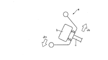
- the steering wheel a vibrates in the opposite direction in the vehicle longitudinal direction above and below the steering shaft c located on the axis passing through the steering center.
- the displacement Ks occurs, and vibrations that stir the steering wheel a occur.
- the airbag module b undergoes a vibration displacement Km above and below the steering shaft c in a direction opposite to the vibration displacement Ks of the steering wheel.
- the vibration of the steering wheel a is effectively suppressed. There was a problem that I could not do it.
- the present invention has been devised in view of the above-mentioned conventional problems, and it is possible to effectively damp the vibration of the steering wheel that causes agitation, and to reduce vibration in both the low frequency band and the high frequency band.
- An object of the present invention is to provide a structure for reducing the vibration of a vehicle steering wheel that contributes.
- a vibration reducing structure for a vehicle steering wheel according to the present invention is a steering wheel for a vehicle, wherein an airbag module serving as a damper mass is attached to a steering wheel via a vibration damping part to dampen the vibration of the steering wheel.
- the structure is characterized in that the airbag module is formed such that a region above a steering center of the steering wheel is lighter in weight than a lower region with reference to a neutral position of the steering wheel.
- the vibration damping parts are arranged so as to surround the steering center, and the airbag module has an installation height of the vibration damping parts located below the steering center with respect to the neutral position of the steering wheel.
- a weight is preferably provided at the position.
- the weight is provided below the installation height position of the vibration damping parts instead of the installation height position of the vibration damping parts.
- the airbag module has a module base to which the vibration damping parts are attached, and the module base is formed so that a region above the steering center is lighter than a region below the steering center with reference to the neutral position of the steering wheel. Preferably.
- the upper region of the module base is made of synthetic resin and the lower region is made of metal.
- the vibration reducing structure for a steering wheel for a vehicle it is possible to effectively damp the vibration of the steering wheel in a fluctuating manner, and to contribute to the reduction of vibration in both the low frequency band and the high frequency band. be able to.
- FIG. 1 is a schematic perspective view of a steering wheel to which a vibration reduction structure for a vehicle steering wheel according to the present invention is applied.
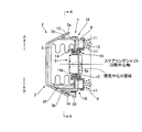
- 1 is a side sectional view showing a preferred embodiment of a vibration reducing structure for a vehicle steering wheel according to the present invention.
- FIG. 3 is a schematic cross-sectional view taken along the line AA in FIG. 2.
- FIG. 3 is an exploded perspective view showing a component configuration of the vehicle steering wheel shown in FIG. 2.
- FIG. 9 is a partial cross-sectional view showing a modified example of the vibration reduction structure for a vehicle steering wheel shown in FIG. 2.
- FIG. 9 is a front view of an attachment plate showing another modification of the vehicle steering wheel vibration reduction structure shown in FIG. 2. It is explanatory drawing explaining the vibration mode in the low frequency band of the steering wheel for vehicles. It is explanatory drawing explaining the vibration mode in the high frequency band of the steering wheel for vehicles.
- FIG. 1 is a diagram exemplifying an outline of a steering wheel 1 to which a vibration reducing structure for a vehicle steering wheel according to the present invention is applied.
- FIG. 1 shows an overall perspective view of the steering wheel 1.
- each direction is illustrated assuming that the steering position of the steering wheel 1 attached to the steering shaft (not shown) of the vehicle is the neutral position.
- the "neutral position of the steering wheel 1" refers to the position of the steering wheel 1 when the vehicle is in a natural state without applying force to the steering wheel 1 while the vehicle is traveling straight ahead.
- the Z axis is roughly defined such that the steering shaft is directed downward toward the front wheels of the vehicle and upward toward the steering wheel 1.
- the direction from 12 o'clock (upward) to 6 o'clock (downward) of the analog 12-hour clock is taken as the Y-axis
- the direction from 9 o'clock (left) to 3 o'clock ( The right direction) is the X axis.
- the side viewed from the driver's side is the front side
- the opposite side is the back side.
- the steering wheel 1 is installed in the driver's seat of the vehicle and is connected to the steering shaft to transmit the steering operation of the driver to the steering gear and the like.
- the steering wheel 1 is steered with a steering shaft as a steering center S.
- the "steering center S of the steering wheel 1" includes the central axis about which the steering shaft rotates (hereinafter referred to as the steering shaft rotation central axis; Z axis direction) and the module base 7 of the airbag module 2.
- the intersection point (preferably orthogonal) with the plane formed by the attachment plate 13, the retainer ring 14, the housing 4, etc., and its vicinity.
- “Upper” and “lower” with respect to the “steering center S” are orthogonal to the rotation center axis in the horizontal direction at the position of the steering center S on the steering shaft rotation center axis extending infinitely as an axis. Assuming a plane that includes a straight line and extends in the direction of the rotation center axis (for example, the ZX plane in FIG. 1), the ceiling direction of the vehicle is the “up” direction and the floor direction is the “down” direction with respect to that plane And
- the “height position” means the vertical distance from the rotation center axis of the steering shaft.
- the vertical position of the steering shaft rotation center axis changes, for example, at the steering angle center S position and the position away from the steering angle center S along the axial direction. That is, the vertical position of the rotation center axis that defines the “height position” by the vertical distance changes in the axial direction. Therefore, the above-mentioned "height position” changes depending on the position of the steering shaft rotation center axis.
- An airbag module 2 that functions as a driver's airbag in an emergency is attached to the center of the steering wheel 1 as shown in FIGS.
- the airbag module 2 which will be described later, normally also functions as a horn switch that is pressed by the driver when the horn sounds.
- the driver side of the airbag module 2 is covered with a resin horn cover 3 that functions as a design surface. As shown in FIGS. 1 to 4, a module base 7 that forms the base of the airbag module is provided behind the horn cover 3.
- an airbag cushion 5 that is attached to the module base 7 and expands and inflates in an emergency is folded and stored.
- An inflator 6 housed in the airbag cushion 5 is attached to the module base 7.
- the inflator gas is supplied from the inflator 6 to the airbag cushion 5, the airbag cushion 5 tears the horn cover 3 and expands and inflates into the passenger compartment space, and to bound.
- the basic part of the steering wheel 1 is composed of a metal cored bar member.
- the core metal member is roughly configured to include a central boss region 8 (see FIG. 3, etc.), a circular rim 9 held by a driver, and a spoke 10 connecting the boss region 8 and the rim 9.
- a steering shaft is connected to the boss region 8.
- the airbag module 2 has a function as a horn switch as described above and a function for reducing the vibration of the steering wheel 1. The configuration for realizing these functions will be described below.
- the airbag module 2 has a module base 7 to which an airbag cushion 5 and an inflator 6 are attached.
- the module base 7 includes a metal retainer ring 14 to which the airbag cushion 5 is attached, a metal attachment plate 13 that is superposed on the back side of the retainer ring 14, and a metal housing 4 that is further superposed on the back side of the attachment plate 13. Composed of.
- the housing 4 has an inflator insertion hole 4a at a central position, and three through holes are arranged around the inflator insertion hole 4a in an array surrounding the steering center S (the rotation center axis of the steering shaft) of the steering wheel 1. 4b is formed.
- the attachment plate 13 and the retainer ring 14 are formed with holes 13a and 14b that communicate with the inflator insertion hole 4a and position the inflator 6 inside the airbag cushion 5.
- the inflator 6 is inserted into the inflator insertion hole 4a from the back side (the boss region 8 side) of the housing 4, and the outer peripheral flange 6s is brought into contact with the housing 4.
- the bolt 14 a provided on the retainer ring 14 penetrates the attachment plate 13, the housing 4 and the outer peripheral flange 6 a of the inflator 6, and the nut 15 is fastened from the back side of the housing 4, whereby the inflator 6 and the airbag cushion 5 are secured. It is attached to the module base 7.
- the module base 7 is further provided with a horn cover 3.
- the horn cover 3 is formed in a hollow bowl shape for accommodating the airbag cushion 5, and a cylindrical portion 3b formed to project from an inner position than the outer peripheral edge portion 3a is engaged with the housing 4 by a locking structure 18. It is stopped and installed.
- the air bag module 2 configured by assembling the air bag cushion 5, the inflator 6, and the horn cover 3 to the module base 7 functions as a damper mass for vibration damping.
- the attachment plate 13 is formed so as to close the three through holes 4b of the housing 4, and constitutes an assembly portion of the vibration damping part 19.
- the vibration damping part 19 is composed of a ring-shaped damping rubber 11 and a shaft-shaped pin body 12.
- the damping rubber 11 is held and provided in each through hole 4b of the housing 4, and is arranged so as to surround the steering center S.
- the pin body 12 is slidably inserted into the damping rubber 11, the disk-shaped base end 12a is abutted against the damping rubber 11 from the front side to prevent the pin 12 from coming off, and the shaft-shaped tip 12b is located in the boss region 8 of the steering wheel 1. Attached and fixed.
- the through hole 4b is closed by the attachment plate 13, and the pin body 12 attached to the boss region 8 is slidably attached to the damping rubber 11 attached to the through hole 4b.
- the airbag module 5 is attached to the steering wheel 1 via the vibration damping part 19 including the pin body 12 on the steering wheel 1 side and the damping rubber 11 on the module base 7 side.
- the pin body 12 transmits the vibration of the steering wheel 1 to the airbag module 2 side, the damping rubber 11 into which the pin body 12 is inserted serves as a vibration damping element, and the airbag module 2 is It serves as a damper mass to dampen the vibration of the steering wheel 1.
- a horn spring (coil spring) 17 is provided to surround each pin body 12 protruding from the housing 4 to the boss region 8.
- the horn spring 17 has one end attached to the boss region 8 and the other end abutted against the back side of the housing 4, whereby the airbag module 2 and the vibration damping parts 19 are installed from the steering wheel 1 side. Elastically supported individually in position.
- the horn spring 17 is installed between the airbag module 2 and the boss region 8 to secure a gap between them.
- the damping rubber 11 airbag module 2
- the spring 17 is compressed.
- the contacts provided on the airbag module 2 side and the steering wheel 1 side are electrically connected, and the horn rings.
- the horn spring 17 elastically restores and the airbag module 2 retracts, whereby the contacts are separated and the ringing is stopped.
- the airbag module 2 steers the steering wheel 1 with reference to the neutral position of the steering wheel 1.
- the region above the center S is formed to be lighter in weight than the region below.
- the airbag module 2 is provided with a weight 20 for adjusting vibration damping characteristics.
- the weight 20 is set in the neutral position above and below the steering wheel 1 in the opposite direction in the vehicle front-rear direction in order to reduce the vibration in the high frequency band that stirs up the steering wheel 1. Is provided at the installation height position of the vibration damping part 19 located below the steering center S.
- one of the vibration damping parts 19 is arranged downward from the steering center S on the 6 o'clock side, which is the downward direction along the Y-axis direction, and the weight 20 is the vibration damping part. It is provided corresponding to the installation height position of 19.
- the weight 20 is attached to the attachment plate 13 so as to be placed on the tubular portion 3b of the horn cover 3, and is provided to the outer peripheral edge portion 3a of the horn cover 3 and the tubular portion 3b. It is fixedly provided in the gap between the shape portion 3b.
- the place where the weight 20 is provided is an example, and any position is the installation height position of the vibration damping parts 19 located below the steering center S with reference to the neutral position of the steering wheel 1. It may be installed in
- the airbag module 2 By setting the airbag module 2 such that the region above the steering center S of the steering wheel 1 is lighter than the region below the steering center S, specifically, by providing the weight 20 below the steering center S, It is possible to appropriately reduce the vibration behavior of the steering wheel 1 in the high frequency band, which is repeatedly swung upward and downward.
- the steering wheel 1 causes vibration displacement in the opposite direction in the vehicle front-rear direction above and below the rotation center axis (steering center S) of the steering shaft, and the steering wheel 1 concerned.
- the vibration mode that causes the vibration is generated, and accordingly, the air bag module 2 effectively vibrates and displaces above and below the steering shaft in a direction opposite to the vibration displacement of the steering wheel 1. Can be dampened.
- the vibration in the low frequency band described above can be reduced by the vibration damping part 19.
- FIG. 5 shows a modification of the above embodiment.
- the weight 20 is provided below the installation height position of the vibration damping part 19 instead of the installation height position of the vibration damping part 19.
- the inertial action of the weight 20 during vibration of the steering wheel 1 can be increased, and even if the weight of the weight 20 is lightened, a considerable vibration reduction effect can be obtained.
- the vibration reducing action of the weight 20 is effective for the vibration of the low frequency band by the vibration damping part 19.
- the vibration reducing effect of the vibration damping part 19 can be applied to the vibration of the high frequency band by the weight 20.
- FIG. 6 shows another modification.
- the module base 7 is formed such that the upper region of the steering center S is lighter than the lower region thereof with reference to the neutral position of the steering wheel 1.
- the arrangement of the vibration damping parts 19 does not matter.
- the module base 7 is composed of the retainer ring 14, the attachment plate 13, and the housing 4.
- All of these parts such as the retainer ring 14 or at least one of these parts is formed so that the weight of the upper region of the steering center S is lighter than that of the lower region.
- the weight may be changed according to any conventionally known method such as changing the material and the member size.
- the upper region (upper half) 13b of the attachment plate 13 is made of light synthetic resin, and the lower region (lower half) 13c is made of heavy metal.
- components such as the attachment plate 13 are made of a combination of synthetic resin and metal, they can be integrally formed by in-mold molding or the like.
- weight change of the upper region and the lower region with respect to the module base 7 described in the modification of FIG. 6 can be adopted in combination with the configuration in which the weight 20 is provided in the above embodiment.
- vibration reduction structure for a vehicle steering wheel is a preferred example of the present invention, and other embodiment examples can be implemented or performed by various methods.
- the present invention is not limited to the detailed shapes, sizes, and arrangements of parts shown in the accompanying drawings unless otherwise specified.
- the expressions and terms used in the specification of the present application are for the purpose of explanation, and are not limited thereto unless otherwise stated.
Landscapes
- Engineering & Computer Science (AREA)
- Mechanical Engineering (AREA)
- Chemical & Material Sciences (AREA)
- Combustion & Propulsion (AREA)
- Transportation (AREA)
- Physics & Mathematics (AREA)
- Fluid Mechanics (AREA)
- Air Bags (AREA)
- Steering Controls (AREA)
- Steering-Linkage Mechanisms And Four-Wheel Steering (AREA)
Abstract
Priority Applications (4)
| Application Number | Priority Date | Filing Date | Title |
|---|---|---|---|
| CN202080009170.XA CN113365899B (zh) | 2019-02-08 | 2020-01-30 | 车辆用方向盘的减振结构 |
| JP2020571132A JP7100164B2 (ja) | 2019-02-08 | 2020-01-30 | 車両用ステアリングホイールの振動低減構造 |
| US17/310,504 US11618501B2 (en) | 2019-02-08 | 2020-01-30 | Vibration reduction structure for vehicle steering wheel |
| EP20752792.0A EP3922536B1 (fr) | 2019-02-08 | 2020-01-30 | Structure de réduction des vibrations pour volant de direction de véhicule |
Applications Claiming Priority (2)
| Application Number | Priority Date | Filing Date | Title |
|---|---|---|---|
| JP2019-021797 | 2019-02-08 | ||
| JP2019021797 | 2019-02-08 |
Publications (1)
| Publication Number | Publication Date |
|---|---|
| WO2020162309A1 true WO2020162309A1 (fr) | 2020-08-13 |
Family
ID=71946980
Family Applications (1)
| Application Number | Title | Priority Date | Filing Date |
|---|---|---|---|
| PCT/JP2020/003388 Ceased WO2020162309A1 (fr) | 2019-02-08 | 2020-01-30 | Structure de réduction des vibrations pour volant de direction de véhicule |
Country Status (5)
| Country | Link |
|---|---|
| US (1) | US11618501B2 (fr) |
| EP (1) | EP3922536B1 (fr) |
| JP (1) | JP7100164B2 (fr) |
| CN (1) | CN113365899B (fr) |
| WO (1) | WO2020162309A1 (fr) |
Cited By (2)
| Publication number | Priority date | Publication date | Assignee | Title |
|---|---|---|---|---|
| JPWO2024009952A1 (fr) * | 2022-07-07 | 2024-01-11 | ||
| CN119412455A (zh) * | 2024-09-20 | 2025-02-11 | 中国舰船研究设计中心 | 一种组合式减振基座及安装方法 |
Families Citing this family (3)
| Publication number | Priority date | Publication date | Assignee | Title |
|---|---|---|---|---|
| EP3922537A4 (fr) * | 2019-02-08 | 2022-11-02 | Autoliv Development AB | Structure d'amortissement de vibrations pour volant de direction et dispositif de volant de direction |
| DE102020126207A1 (de) * | 2020-10-07 | 2022-04-07 | ZF Automotive Safety Germany GmbH | Gassackmodulbaugruppe, verfahren zu deren herstellung und qualitätsprüfung sowie fahrzeuglenkrad mit einer solchen gassackmodulbaugruppe |
| USD1039455S1 (en) * | 2022-06-16 | 2024-08-20 | Huawei Technologies Co., Ltd. | Steering wheel for vehicles |
Citations (7)
| Publication number | Priority date | Publication date | Assignee | Title |
|---|---|---|---|---|
| JPH0585368A (ja) * | 1991-09-27 | 1993-04-06 | Nippon Plast Co Ltd | ステアリングホイール |
| JPH06191417A (ja) * | 1992-12-25 | 1994-07-12 | Toyoda Gosei Co Ltd | ステアリングホイール |
| JPH07137595A (ja) * | 1993-11-16 | 1995-05-30 | Nippon Plast Co Ltd | ステアリングホイール |
| JPH09309398A (ja) * | 1996-05-24 | 1997-12-02 | Nippon Plast Co Ltd | ステアリングホイール |
| WO2012147524A1 (fr) * | 2011-04-27 | 2012-11-01 | オートリブ ディベロップメント エービー | Structure de volant pour véhicule |
| JP2015145173A (ja) | 2014-02-03 | 2015-08-13 | タカタ株式会社 | ステアリングホイール |
| JP2015160438A (ja) * | 2014-02-25 | 2015-09-07 | オートリブ ディベロップメント エービー | ステアリングホイール装置 |
Family Cites Families (15)
| Publication number | Priority date | Publication date | Assignee | Title |
|---|---|---|---|---|
| JPH09303478A (ja) * | 1996-05-14 | 1997-11-25 | Nippon Plast Co Ltd | 振動抑制装置およびステアリングホイール |
| KR100471827B1 (ko) * | 2002-04-09 | 2005-03-08 | 현대자동차주식회사 | 진동 저감형 차량의 조향휠 |
| US7384064B2 (en) * | 2004-04-20 | 2008-06-10 | General Motors Corporation | Driver air bag module and method of assembly |
| JP2006228700A (ja) * | 2004-12-17 | 2006-08-31 | Tkj Kk | ホーンスイッチ装置、エアバッグ装置及びステアリングホイール |
| JP5153526B2 (ja) * | 2008-02-01 | 2013-02-27 | 本田技研工業株式会社 | ステアリングホイールの振動低減構造 |
| DE102011017350B4 (de) * | 2011-04-18 | 2013-01-24 | Autoliv Development Ab | Vorrichtung zur Dämpfung von Schwingungen |
| JP2013071626A (ja) * | 2011-09-28 | 2013-04-22 | Toyoda Gosei Co Ltd | ステアリングホイールの制振構造 |
| US20170144690A1 (en) * | 2013-03-15 | 2017-05-25 | Autoliv Asp, Inc. | Steering wheel vibration suppressors |
| DE102013012010B4 (de) * | 2013-07-18 | 2023-02-02 | Zf Airbag Germany Gmbh | Schwingungsdämpfender Gasgenerator und Airbagmodul für ein Kraftfahrzeug mit einem solchen Gasgenerator |
| JP2015071402A (ja) * | 2013-09-04 | 2015-04-16 | オートリブ ディベロップメント エービー | ステアリングホイール装置 |
| JP2016199183A (ja) * | 2015-04-13 | 2016-12-01 | タカタ株式会社 | ステアリングホイール |
| US9963099B2 (en) * | 2016-01-26 | 2018-05-08 | Ford Global Technologies, Llc | Steering wheel assembly including an airbag tether |
| CN106275050A (zh) * | 2016-08-10 | 2017-01-04 | 重庆长安汽车股份有限公司 | 吸能装置及方向盘骨架 |
| CN110712674B (zh) * | 2018-07-11 | 2022-01-25 | 奥托立夫开发公司 | 方向盘的减震器机构和车辆用方向盘装置 |
| EP3922537A4 (fr) * | 2019-02-08 | 2022-11-02 | Autoliv Development AB | Structure d'amortissement de vibrations pour volant de direction et dispositif de volant de direction |
-
2020
- 2020-01-30 US US17/310,504 patent/US11618501B2/en active Active
- 2020-01-30 WO PCT/JP2020/003388 patent/WO2020162309A1/fr not_active Ceased
- 2020-01-30 EP EP20752792.0A patent/EP3922536B1/fr active Active
- 2020-01-30 JP JP2020571132A patent/JP7100164B2/ja active Active
- 2020-01-30 CN CN202080009170.XA patent/CN113365899B/zh active Active
Patent Citations (7)
| Publication number | Priority date | Publication date | Assignee | Title |
|---|---|---|---|---|
| JPH0585368A (ja) * | 1991-09-27 | 1993-04-06 | Nippon Plast Co Ltd | ステアリングホイール |
| JPH06191417A (ja) * | 1992-12-25 | 1994-07-12 | Toyoda Gosei Co Ltd | ステアリングホイール |
| JPH07137595A (ja) * | 1993-11-16 | 1995-05-30 | Nippon Plast Co Ltd | ステアリングホイール |
| JPH09309398A (ja) * | 1996-05-24 | 1997-12-02 | Nippon Plast Co Ltd | ステアリングホイール |
| WO2012147524A1 (fr) * | 2011-04-27 | 2012-11-01 | オートリブ ディベロップメント エービー | Structure de volant pour véhicule |
| JP2015145173A (ja) | 2014-02-03 | 2015-08-13 | タカタ株式会社 | ステアリングホイール |
| JP2015160438A (ja) * | 2014-02-25 | 2015-09-07 | オートリブ ディベロップメント エービー | ステアリングホイール装置 |
Non-Patent Citations (1)
| Title |
|---|
| See also references of EP3922536A4 |
Cited By (4)
| Publication number | Priority date | Publication date | Assignee | Title |
|---|---|---|---|---|
| JPWO2024009952A1 (fr) * | 2022-07-07 | 2024-01-11 | ||
| WO2024009952A1 (fr) * | 2022-07-07 | 2024-01-11 | オートリブ ディベロップメント エービー | Dispositif de coussin de sécurité gonflable disposé sur un volant de direction |
| JP7846766B2 (ja) | 2022-07-07 | 2026-04-15 | オートリブ ディベロップメント エービー | ステアリングホイールに備えられるエアバッグ装置 |
| CN119412455A (zh) * | 2024-09-20 | 2025-02-11 | 中国舰船研究设计中心 | 一种组合式减振基座及安装方法 |
Also Published As
| Publication number | Publication date |
|---|---|
| US11618501B2 (en) | 2023-04-04 |
| EP3922536B1 (fr) | 2023-12-06 |
| CN113365899A (zh) | 2021-09-07 |
| JP7100164B2 (ja) | 2022-07-12 |
| US20220119037A1 (en) | 2022-04-21 |
| EP3922536A4 (fr) | 2022-11-09 |
| EP3922536A1 (fr) | 2021-12-15 |
| JPWO2020162309A1 (ja) | 2021-10-28 |
| CN113365899B (zh) | 2023-02-28 |
Similar Documents
| Publication | Publication Date | Title |
|---|---|---|
| JP7100164B2 (ja) | 車両用ステアリングホイールの振動低減構造 | |
| KR101964936B1 (ko) | 진동 가능한 방식으로 차량 조향 휠에 에어백 모듈을 부착하기 위한 커플링 장치 | |
| JP7100165B2 (ja) | 車両用ステアリングホイールの振動減衰構造及び車両用ステアリングホイール装置 | |
| JP5765284B2 (ja) | ステアリングホイールの制振構造 | |
| CN110962911B (zh) | 车辆方向盘所具备的减振器结构 | |
| JP5878827B2 (ja) | インフレータ用ディフューザ及びエアバッグ装置 | |
| JP4852063B2 (ja) | ステアリングホイールの振動低減構造 | |
| JP2011195048A (ja) | ステアリングホイールの制振構造及びステアリングホイール用ダンパゴム | |
| JP2013203343A (ja) | エアバッグ装置 | |
| JP2012071754A (ja) | エアバッグ装置 | |
| JP2009262785A (ja) | 車両用ステアリングホイール | |
| JP4673798B2 (ja) | ダイナミックダンパ | |
| JP2012254790A (ja) | ステアリングホイールの振動低減構造 | |
| JP2008179295A (ja) | コラム付けニーエアバッグ装置 | |
| CN116056968A (zh) | 车辆方向盘装置 | |
| JP2012091683A (ja) | エアバッグ装置 | |
| CN117751070A (zh) | 方向盘 | |
| JP2012218679A (ja) | エアバッグ装置 | |
| JP2013203342A (ja) | エアバッグ装置 |
Legal Events
| Date | Code | Title | Description |
|---|---|---|---|
| 121 | Ep: the epo has been informed by wipo that ep was designated in this application |
Ref document number: 20752792 Country of ref document: EP Kind code of ref document: A1 |
|
| ENP | Entry into the national phase |
Ref document number: 2020571132 Country of ref document: JP Kind code of ref document: A |
|
| NENP | Non-entry into the national phase |
Ref country code: DE |
|
| ENP | Entry into the national phase |
Ref document number: 2020752792 Country of ref document: EP Effective date: 20210908 |
|
| ENP | Entry into the national phase |
Ref document number: 2020752792 Country of ref document: EP Effective date: 20210908 |