WO2020162341A1 - Capteur - Google Patents
Capteur Download PDFInfo
- Publication number
- WO2020162341A1 WO2020162341A1 PCT/JP2020/003596 JP2020003596W WO2020162341A1 WO 2020162341 A1 WO2020162341 A1 WO 2020162341A1 JP 2020003596 W JP2020003596 W JP 2020003596W WO 2020162341 A1 WO2020162341 A1 WO 2020162341A1
- Authority
- WO
- WIPO (PCT)
- Prior art keywords
- electric wire
- wire insertion
- insertion portion
- electrode
- respect
- Prior art date
- Legal status (The legal status is an assumption and is not a legal conclusion. Google has not performed a legal analysis and makes no representation as to the accuracy of the status listed.)
- Ceased
Links
Images


Classifications
-
- F—MECHANICAL ENGINEERING; LIGHTING; HEATING; WEAPONS; BLASTING
- F16—ENGINEERING ELEMENTS AND UNITS; GENERAL MEASURES FOR PRODUCING AND MAINTAINING EFFECTIVE FUNCTIONING OF MACHINES OR INSTALLATIONS; THERMAL INSULATION IN GENERAL
- F16B—DEVICES FOR FASTENING OR SECURING CONSTRUCTIONAL ELEMENTS OR MACHINE PARTS TOGETHER, e.g. NAILS, BOLTS, CIRCLIPS, CLAMPS, CLIPS OR WEDGES; JOINTS OR JOINTING
- F16B7/00—Connections of rods or tubes, e.g. of non-circular section, mutually, including resilient connections
- F16B7/18—Connections of rods or tubes, e.g. of non-circular section, mutually, including resilient connections using screw-thread elements
-
- G—PHYSICS
- G01—MEASURING; TESTING
- G01R—MEASURING ELECTRIC VARIABLES; MEASURING MAGNETIC VARIABLES
- G01R15/00—Details of measuring arrangements of the types provided for in groups G01R17/00 - G01R29/00, G01R33/00 - G01R33/26 or G01R35/00
- G01R15/14—Adaptations providing voltage or current isolation, e.g. for high-voltage or high-current networks
- G01R15/16—Adaptations providing voltage or current isolation, e.g. for high-voltage or high-current networks using capacitive devices
Definitions
- the present invention relates to a sensor capable of detecting a detected amount of a covered electric wire in a non-contact state with a conductor of the covered electric wire.
- the applicant has disclosed a voltage sensor capable of detecting the voltage supplied to the covered electric wire in a non-contact state with the core wire (conductor) of the covered electric wire in the following patent document.
- This voltage sensor includes an electrode portion having an electrode that is capacitively coupled to a core wire through an insulating coating of a covered electric wire when measuring a voltage, and a screw formed into a cylindrical shape into which the electrode portion can be inserted and integrated with the electrode portion.
- Part hereinafter, the element other than the electrode in the electrode part and the element composed of the screw part are also referred to as "electrode holding part" and the electrode holding part are formed into a cylindrical shape into which a covered electric wire can be inserted.
- a male screw is formed on the outer peripheral surface of the electrode holding portion, and a female screw capable of screwing the male screw of the electrode holding portion is formed on the inner peripheral surface of the wire insertion portion.
- the voltage sensor When measuring the voltage using this voltage sensor, attach the voltage sensor to the insulated wire. Specifically, first, the covered electric wire is inserted into the notch of the electric wire insertion portion so that the covered electric wire is inserted into the electric wire insertion portion. Next, the electrode holding part in which the lock nut is screwed onto the male screw is screwed into the wire insertion part along the axial direction from the base end side of the wire insertion part. At this time, the electrode integrated with the electrode holding portion is moved together with the electrode holding portion toward the tip end side of the wire inserting portion as the electrode holding portion is rotated (screwed) with respect to the electric wire inserting portion. As a result, the tip end surface of the electrode comes into contact with the insulating coating of the coated electric wire inserted into the electric wire insertion portion.
- the electrode holding portion is further moved toward the tip end side of the wire insertion portion, and the tip end surface of the electrode is pressed against the covered electric wire (insulation coating).
- the covered electric wire is sandwiched between the edge portion of the notch in the electric wire insertion portion and the tip surface of the electrode.
- the lock nut is rotated with respect to the electrode holding portion (male screw) so that the lock nut is pressed against the base end portion of the wire insertion portion.
- the relative rotation (loosening) of the electrode holding portion with respect to the wire insertion portion is restricted, and the mounting of the voltage sensor on the covered electric wire is completed.
- the voltage sensor is connected to the measuring device by connecting a connection cable to the connector provided at the base end of the voltage sensor. After that, by operating the operation unit of the measuring device to execute the measurement process, the voltage of the covered electric wire is detected and measured via the voltage sensor.
- the connection cable is removed from the voltage sensor.
- the electrode holding part male screw
- the electrode holding part with respect to the wire insertion part Release the rotation restriction.
- the electrode holding part is rotated with respect to the electric wire insertion part in a direction opposite to that at the time of mounting.
- the electrode held by the electrode holding part is moved together with the electrode holding part toward the proximal end side of the electric wire insertion part, The tip end surface of the electrode is separated from the covered electric wire inserted in. Then, the detached work is completed by removing the covered electric wire from the notch of the electric wire insertion portion.
- the voltage sensor disclosed by the applicant has the following issues to be improved. Specifically, in the voltage sensor disclosed by the applicant, the tip end surface of the electrode held by the electrode holding part is screwed by screwing the electrode holding part (male screw) into the wire insertion part (female screw). The covered electric wire is sandwiched between the electric wire insertion part and the edge of the cutout in the electric wire insertion part, whereby the electrode is pressed against the covered electric wire (insulation coating), and the electrode holding part for the electric wire insertion part is held by the lock nut. Is used to regulate the relative rotation (loosening) of the electrode to regulate the relative movement of the electrode with respect to the coated electric wire (insulating coating).
- the lock nut is rotated with respect to the electrode holding portion so that the relative rotation (loosening) of the electrode holding portion with respect to the electric wire insertion portion can be appropriately regulated. Move it so that the lock nut is pressed against the base end of the wire insertion part with sufficient pressing force.
- the sensor when detecting the amount to be detected using this type of sensor, the sensor may be attached to the coated electric wire arranged in the vicinity of various heating elements such as the engine, motor, transformer and arithmetic processor. Also, when detecting the detected amount of the covered electric wire arranged near the heating element, specify the detected amount in the stopped/operating state of the device to which the covered electric wire is connected, and check the sensor safety against the covered electric wire. In some cases, the mounting work is performed while the device is stopped for the purpose of various mounting works. Further, detection of the detected amount using this type of sensor is performed inside a running vehicle or in the vicinity of an operating machine tool (that is, in an environment where vibration is applied to the sensor or the covered electric wire). Sometimes.
- the voltage sensor when the device is stopped (that is, the heating element is not generating heat), the voltage sensor is attached to the covered wire, and when the device is subsequently moved to the operating state, the heating element generates heat. Thermal expansion of the voltage sensor and covered wire.
- the voltage sensor when the voltage sensor is composed of a combination of materials such that the coefficient of thermal expansion of the wire insertion part or the lock nut is lower than the coefficient of thermal expansion of the electrode holding part, heat generated by the above-mentioned heating element, etc.
- the temperature of the voltage sensor is raised and each part is thermally expanded, the pressing force of the lock nut against the base end portion of the wire insertion part may be reduced, and the rotation restricting force of the lock nut may be reduced.
- the work of attaching the sensor to the coated electric wire may be performed in an environment of higher temperature than when detecting.
- each part of the voltage sensor contracts as the temperature decreases when the environment is changed to a temperature lower than that when it is attached to the covered electric wire.
- a combination of materials such that the coefficient of thermal expansion of the wire insertion part or the lock nut is higher than that of the electrode holding part (the contraction rate of the electrode holding part when the temperature drops
- the voltage sensor is made up of a combination of materials such that the contraction rate of the nut is higher
- the parts are contracted due to the contraction of the parts when they are moved to a lower temperature environment than when they are installed.
- the pressing force of the lock nut against the base end of the lock nut may decrease and the rotation restricting force of the lock nut may decrease.
- the wire insertion part rotates with respect to the electrode holding part when the rotation restricting force by the lock nut is lowered as described above, and the wire insertion part is inserted.
- a gap may be formed between the coated electric wire (insulating coating) inserted in the portion and the electrode.
- the voltage sensor easily moves with respect to the coated wire along the longitudinal direction of the coated wire, but also the distance between the core wire (conductor wire) and the electrode of the coated wire changes and As a result of the change in the degree of capacitive coupling of the electrodes, it may be difficult to accurately detect the detected amount (voltage).
- the electrode holding part is rotated from the covered electric wire by rotating the electrode holding part with respect to the electric wire insertion part in the opposite direction to that when the electrode holding part is screwed into the electric wire insertion part.
- the structure that separates is adopted.
- this voltage sensor there is a configuration in which the electric wire insertion portion and the electrode holding portion are maintained in an integrated state by screwing the female screw provided on the electric wire insertion portion and the male screw provided on the electrode holding portion. Has been adopted. Therefore, in this voltage sensor, the wire insertion portion and the electrode holding portion are separated by releasing the screwing of the male screw of the electrode holding portion with the female screw of the wire insertion portion.
- the present invention has been made in view of such problems to be improved, and a main object of the present invention is to provide a sensor capable of suitably avoiding unintentional rotation of the wire insertion part with respect to the electrode holding part. Another object is to provide a sensor that can avoid unintended separation of the electrode holding part and the wire insertion part.
- the senor according to claim 1 has a cylindrical electrode holding portion, and a state in which the electrode holding portion is inserted into the electrode holding portion and is held by the electrode holding portion, and with respect to a conductor of a covered electric wire. And an electrode that is brought into close proximity through the insulating coating of the covered electric wire and capacitively coupled to the conductor wire, and the covered electric wire can be inserted into the notch formed in a tubular shape and having a part of the peripheral wall cut out.
- a wire insertion portion configured, and the outer peripheral surface of the electrode holding portion and the inner peripheral surface of the electric wire insertion portion, and the outer peripheral surface of the electric wire insertion portion and the inner peripheral surface of the electrode holding portion to each other Threaded portions that can be screwed are respectively formed, and the relative rotation of the electrode holding portion with respect to the electric wire insertion portion causes the electric wire insertion portion and the electrode holding portion along the tube length direction to the electric wire insertion portion.
- the electrode holding part is moved relatively, the approaching direction in which the electrode held by the electrode holding part approaches the covered electric wire inserted in the electric wire insertion part, and the electrode from the covered electric wire.
- the electrode holding portion is formed into a tubular shape capable of inserting the electrode, the screw portion is formed, and the electrode holding portion is rotated relative to the wire insertion portion. Is formed into a tubular shape that allows the first member to be inserted therethrough, relative movement in the tubular length direction with respect to the first member is permitted, and with respect to the first member.
- An insertion portion side engaging portion is provided in the insertion portion side abutting portion with which the second member abuts in the electric wire inserting portion, and a holding portion is abutted with the insertion portion side abutting portion in the second member.
- a holding portion side engaging portion that is engageable with the insertion portion side engaging portion is provided in the portion side contact portion, and the insertion portion side engaging portion and the holding portion side engaging portion are engaged with each other. By doing so, the relative rotation of the second member with respect to the electric wire insertion portion is restricted.
- the urging member is formed of a coil spring capable of inserting the first member, and is arranged in the second member together with the first member. ing.
- the insertion portion side engagement portions are formed at equal intervals along the circumferential direction of the electric wire insertion portion in the insertion portion side contact portion.
- a plurality of insertion-portion-side convex portions, and the holding-portion-side engaging portions engage with the insertion-portion-side concave portions between the insertion-portion-side convex portions that are adjacent to each other in the circumferential direction of the wire insertion portion.
- the second member with respect to the first member of the insertion-portion-side projections that are adjacent to each other in the circumferential direction of the wire insertion portion The electric wire when the first member is moved relative to the electric wire insertion portion in the approaching direction by rotating the first member with respect to the electric wire insertion portion with rotation of the electric wire insertion portion.
- the bottom of the insertion portion side concave portion between the top of the insertion portion side convex portion and the adjacent insertion portion side convex portion located on the side in the approaching rotation direction that is the rotation direction of the second member with respect to the insertion portion. Is located on the side of the adjacent turning direction of the adjacent insertion-portion-side convex portion that is opposite to the approaching turning direction than the first distance along the approaching turning direction.
- the second distance along the rotation direction at the time of separation between the top portion of the insertion portion side convex portion and the bottom portion of the insertion portion side concave portion between the adjacent insertion portion side convex portions is shortened.
- the tops of the holder-side protrusions that are located on the approach rotation direction side are equal to the second distance, and the adjacent holding portion.
- the sensor according to claim 4 is the sensor according to any one of claims 1 to 3, wherein the first member holds the electrode with respect to the insulating coating of the coated electric wire inserted into the electric wire insertion portion.
- the first member holds the electrode with respect to the insulating coating of the coated electric wire inserted into the electric wire insertion portion.
- the sensor according to claim 5 is the sensor according to any one of claims 1 to 4, wherein the second member is formed of a first resin material containing at least one of a phosphorescent pigment and a fluorescent pigment.
- the sensor according to claim 6 is the sensor according to any one of claims 1 to 5, wherein the sensor is disposed between the electrode holding portion and the wire insertion portion and is relative to the electrode holding portion in the cylinder length direction.
- the third member is provided which abuts on a member abutting convex portion provided on the peripheral surface of the electrode holding portion and restricts relative movement of the wire insertion portion with respect to the electrode holding portion in the separating direction. ..
- the sensor according to claim 7 is the sensor according to claim 6, wherein the third member is formed in an annular shape and is press-fitted into the electric wire insertion portion and fixed to the electric wire insertion portion.
- the sensor according to claim 8 is the sensor according to claim 7, wherein the electrode holding part is provided with only one member contacting convex part, and the third member is formed in a C shape.
- the circumferential length of the gap between the one end portion and the other end portion of the third member in the circumferential direction is along the circumferential direction of the electrode holding portion in a state where the third member is not press-fitted into the wire insertion portion.
- Elastic deformation of the member contacting convex portion which is equal to or longer than the length and is shorter than the length of the member contacting convex portion along the circumferential direction of the electrode holding portion in a state of being press-fitted into the wire insertion portion. It is configured to be possible.
- the sensor according to claim 9 is the sensor according to any one of claims 1 to 8, wherein one end portion of the wire insertion portion in the cylinder length direction is opened so that the electrode holding portion and the third member can be inserted. And the other end in the cylinder length direction is closed, and the inner surface of the electric wire insertion portion has a facing surface facing the tip end surface of the electrode held by the electrode holding portion, and the opposite surface of the electric wire insertion portion has a cylinder.
- An electric wire contact portion is provided which is formed so as to be linearly continuous with a part of the inner edge portion on the other end side of the notch in the radial direction.
- the sensor according to claim 10 is the sensor according to claim 9, wherein the wire insertion part has an opening width along the circumferential direction of the wire insertion part on the other end side of the notch from the one end part.
- the other end side of the notch is formed in an arc shape so as to become narrower toward the other end, and the wire contact portion is provided on the top of the inner edge of the notch on the other end side. Is provided.
- the sensor according to claim 11 is the sensor according to any one of claims 1 to 10, wherein the wire insertion portion is formed of a second resin material containing at least one of a phosphorescent pigment and a fluorescent pigment.
- the electrode holding portion is formed in a tubular shape through which the electrode can be inserted, a screw portion is formed, and a relative rotation with respect to the electric wire insertion portion is allowed.
- the first member is formed in a tubular shape that can be inserted, the relative movement in the tubular length direction with respect to the first member is allowed, and the relative rotation with respect to the first member is restricted.
- the second member attached to the first member and the biasing member that biases the second member in the approaching direction with respect to the first member, and the insertion portion side contact with which the second member abuts in the wire insertion portion.
- the insertion section side engaging section is provided in the contact section, and the holding section side is engageable with the insertion section side engaging section in the holding section side contact section that is brought into contact with the insertion section side contact section in the second member.
- the engaging portion is provided, and the insertion portion side engaging portion and the holding portion side engaging portion are engaged with each other, whereby the relative rotation of the second member with respect to the electric wire inserting portion is restricted. Has been done.
- the sensor of claim 1 even if thermal expansion or contraction occurs in each part of the sensor due to temperature change, unless the second member is moved in the separating direction against the urging force of the urging member. , The insertion portion side engaging portion and the holding portion side engaging portion are maintained in the engaged state, and the rotation of the second member with respect to the electric wire insertion portion, that is, the rotation of the first member with respect to the electric wire insertion portion is restricted. The state is maintained. This avoids the situation in which the first member and the electrode move in the separating direction with respect to the wire insertion portion due to the unintentional rotation of the first member with respect to the wire insertion portion, and the electrode is pressed against the covered electric wire. The state can be maintained appropriately.
- the biasing member is configured by the coil spring that can insert the first member, unlike the configuration in which the leaf spring or the like is adopted as the biasing member, the second member for the wire insertion portion is provided. Regardless of the rotational posture of the member, it is possible to urge the second member against the first member with a suitable urging force so that the second member is pressed against the wire insertion portion.
- the top portion of the insertion portion side convex portion located on the side of the insertion portion side convex portion adjacent in the circumferential direction of the electric wire insertion portion in the approach rotation direction side When the insertion-portion-side recesses between the adjacent insertion-portion-side projections approach the bottom portion, when the insertion-portion-side projections that are circumferentially adjacent to each other are separated from the first distance along the rotation direction.
- the second distance along the rotation direction is short when the top portion of the insertion portion side convex portion located on the rotation direction side and the bottom portion of the insertion portion side concave portion between both adjacent insertion portion side convex portions are separated from each other.
- Each insertion portion side convex portion is formed so that the holding portion side engaging portion has a holding portion side convex portion adjacent to the holding portion side engaging portion in the circumferential direction of the holding portion side engaging portion, which is located on the rotation direction side when approaching.
- the third distance along the rotation direction when approaching the top part of the part-side convex part and the bottom part of the holding-part-side concave part between both adjacent holding-part-side convex parts becomes equal to the second distance, and Of the holding portion side convex portions located adjacent to the holding portion side convex portion located on the rotation direction side at the time of separation of the holding portion side convex portions adjacent to each other in the direction and the bottom portion of the holding portion side concave portion between the adjacent holding portion side convex portions.
- Each holding portion side convex portion is formed so that the fourth distance along the time rotation direction is equal to the first distance.
- the movement of the second member in the approaching direction with respect to the first member is restricted and held from the insertion portion side contact portion. Since the first member is provided with the movement restricting portion that keeps the part-side abutting part separated, the holding-part-side engaging part and the holding-part-side engaging part are provided when the electrode is moved toward the covered electric wire in the notch. Since the second member can be rotated with respect to the electric wire insertion portion with which the first member is engaged, the second member can be easily rotated while the insertion portion side engaging portion is not engaged.
- the holding part side engaging part and the insertion part side engaging part are engaged.
- the unintentional rotation of the second member with respect to the first member can be appropriately regulated.
- the second member is formed of the first resin material containing at least one of the phosphorescent pigment and the fluorescent pigment, when the sensor is attached to the covered electric wire in a dark place, or in a dark place.
- the position of the sensor can be surely and easily grasped by the light emission of the second member and the increase in the amount of light reflected by the second member. It is possible to sufficiently improve the sex. Further, since the position of the second member can be reliably and easily grasped by the increase in the amount of emitted light or the reflection of light, the second member can be reliably and easily gripped and operated accurately.
- the senor is arranged between the electrode holding portion and the electric wire insertion portion, is fixed to the electric wire insertion portion in a state of being movable relative to the electrode holding portion in the cylinder length direction, and the electrode
- the wire insertion part is moved relatively to the holding part in the separating direction to the predetermined position, it contacts the member contacting convex part provided on the peripheral surface of the electrode holding part to hold the electrode.
- a third member for restricting relative movement of the electric wire insertion portion with respect to the portion in the separating direction.
- the third member is formed in an annular shape, and the third member is press-fitted into the electric wire insertion part and fixed to the electric wire insertion part, which is different from the structure in which the third member is fixed by adhesion or screwing. Since the third member can be easily fixed to the wire insertion portion, its manufacturing cost can be sufficiently reduced.
- the electrode holding portion is provided with only one member abutting convex portion
- the third member is formed in a C shape
- the third member is provided with one end portion in the circumferential direction.
- the length in the circumferential direction in the gap between the other end is equal to or longer than the length of the member abutting convex portion along the circumferential direction of the electrode holding portion in a state where it is not press-fitted into the wire insertion portion, and the wire insertion It is configured to be elastically deformable so as to be shorter than the length of the member abutting convex portion along the circumferential direction of the electrode holding portion in a state of being press-fitted into the portion.
- the member contacting convex part passes through the gap between the one end part and the other end part in the circumferential direction of the third member.
- the third member is relatively moved so that the third member is located closer to the base end side than the member abutting protrusion of the electrode holding part, and then the electrode holding part of the electrode abutting part is moved relative to the member abutting protrusion. Fixing the third member in the wire insertion part by inserting the electrode holding part into the wire insertion part while rotating the third member so that there is no gap between the third member in the cylinder length direction.
- the third member can be reliably and easily fixed in the electric wire insertion portion, and the member abutting convex portion is moved to the first position when the electric wire insertion portion is relatively moved with respect to the electrode holding portion in the separating direction.
- one end of the wire insertion portion in the cylinder length direction is opened so that the electrode holding part and the fourth member can be inserted, and the other end of the wire insertion portion in the cylinder length direction is closed.
- the inner surface of the wire insertion portion which is opposed to the tip end surface of the electrode held by the electrode holding portion, is in line with a part of the inner edge portion of the wire insertion portion on the other end side in the cylinder radial direction.
- a wire contact portion is provided in the wire insertion portion.
- the insulated wire can be sandwiched between the wire insertion portion and the electrode without causing a situation in which the insulating coating is deformed or a wire breakage (disconnection of the conductor wire) occurs, Can be securely held without being damaged (the sensor can be surely attached to the covered electric wire).
- the other end portion of the notch is such that the opening width along the circumferential direction of the electric wire insertion portion on the other end portion side of the notch becomes narrower from one end portion toward the other end portion.
- Side is formed in an arc shape, and the wire contact portion is provided on the top of the inner edge of the notch on the other end side to form the wire insertion part, so that the covered wire inserted in the notch is securely It can be brought into contact with the electric wire contact portion.
- the wire insertion portion is formed of the second resin material containing at least one of the phosphorescent pigment and the fluorescent pigment, when the sensor is attached to the covered wire in a dark place, or in a dark place.
- the position of the sensor can be reliably and easily grasped by the light emission of the wire insertion part and the increase in the amount of light reflected by the wire insertion part. It is possible to sufficiently improve the sex.
- the position of the notch where the covered electric wire should be inserted can be reliably and easily grasped by the light emission of the electric wire insertion portion and the increase in the amount of light reflected by the electric wire insertion portion, the workability of the mounting work is sufficiently improved.
- the position of the covered electric wire inserted into the notch can be grasped reliably and easily, the workability of the detaching work can be sufficiently improved.
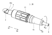
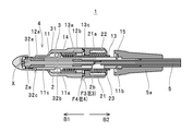
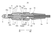
- FIG. 1 It is an external appearance perspective view of the voltage sensors 1 and 1B. It is another external appearance perspective view of the voltage sensors 1 and 1B.
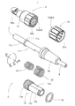
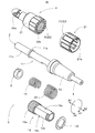
- 3 is an exploded perspective view of the voltage sensor 1.
- FIG. FIG. 6 is another exploded perspective view of the voltage sensor 1.
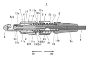
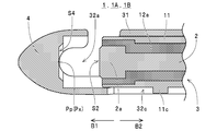
- 5 is a cross-sectional view of the voltage sensor 1 in a state where the covered electric wire X is inserted into the cutout 32a of the electric wire insertion portion 4.
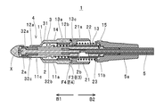
- FIG. It is sectional drawing of the state which moved the electrode holding part 3 to the electric wire insertion part 4 in the direction of arrow B1 from the state shown in FIG. It is sectional drawing for demonstrating the state by which the engaging part E3 of the electrode holding part 3 and the engaging part E4 of the electric wire insertion part 4 were made to engage.
- FIG. 8 is a cross-sectional view for explaining a state in which the electrode holding portion 3 is rotated in the direction of arrow A1 with respect to the wire insertion portion 4 from the state shown in FIG. 7. It is sectional drawing for demonstrating the state to which the electrode 2 was pressed with respect to the covered electric wire X, and the engaging parts E3 and E4 were made to engage.
- FIG. 10 is a cross-sectional view of a state in which the tubular portion 13 of the electrode holding portion 3 is further moved in the direction of arrow B1 with respect to the wire insertion portion 4 from the state shown in FIG. 9.
- FIG. 7 is a cross-sectional view showing a state where the operation knob 21 is moved in the direction of arrow B2 with respect to the tubular portion 13.
- FIG. 4 is an external perspective view of the wire insertion portion 4 on the tip end side.
- FIG. 11 is an exploded perspective view of a voltage sensor 1B according to still another embodiment. It is another exploded perspective view of the voltage sensor 1B.
- FIG. 7 is a cross-sectional view of the voltage sensor 1B in a state in which the covered electric wire X is inserted into the cutout 32a of the electric wire insertion portion 4.
- FIG. 7 is a cross-sectional view of the voltage sensor 1B in a state where the tubular portion 13 of the electrode holding portion 3 is moved in the direction of arrow B1 with respect to the electric wire insertion portion 4.
- the voltage sensor 1 shown in FIGS. 1 and 2 is an example of a “sensor”, and is a coated electric wire X (example of “coated electric wire”: see FIG. 5) in which a conductive wire (core wire) is covered with an insulating coating and insulated.
- the supplied voltage (an example of “amount to be detected for the covered electric wire”) can be detected in a non-contact state with respect to the conducting wire of the covered electric wire X.
- the voltage sensor 1 includes an electrode 2, an electrode holding portion 3, and an electric wire insertion portion 4, is configured to be attachable to the covered electric wire X to be detected (the covered electric wire X can be inserted), and sends a signal to a measuring device (not shown). It is configured to be connectable via a cable 5.
- the electrode 2 is an example of an “electrode”, and is formed in a columnar shape (a cylindrical shape in this example) with a conductive metal material as shown in FIG. 5, and is inserted into the wire insertion portion 4 as described later. With the tip portion 2a (tip surface S2: see FIG. 13) pressed against the covered electric wire X, the conductor wire of the covered electric wire X is capacitively coupled via the insulating coating of the covered electric wire X. As shown in FIG. 13, the electrode 2 is inserted into the holder main body 11 such that the tip 2a (tip surface S2) is exposed from the holder main body 11 of the electrode holder 3 which will be described later. As shown in FIG. 5, the signal cable 5 is connected to the base end portion 2b in the holding portion main body 11 while being integrated with the above.
- the electrode holding part 3 is an example of an “electrode holding part” and is formed in a tubular shape (cylindrical shape in this example) as a whole. As shown in FIGS. 3 and 4, the electrode holding portion 3 includes a holding portion body 11, insulators 12a and 12b (see FIG. 5), a tubular portion 13, a coil spring 14, an operating knob 21, and a coil spring 22. I have it.
- the holding portion main body 11 is a member that constitutes the “first member” in cooperation with the insulators 12 a and 12 b, the tubular portion 13, and the coil spring 14, and as an example, the electrode 2 is made of a conductive metal material. It is formed in a cylindrical shape (cylindrical shape) through which the insert is inserted. As will be described later, the holding portion main body 11 is formed with a convex portion 11a with which one end portion of the coil spring 14 is brought into contact with the central portion in the longitudinal direction, and the tubular portion 13 is moved with respect to the holding portion main body 11. A groove 11b (see FIGS. 5, 6 and the like) into which a stopper 15 (snap ring) for restricting can be fitted is formed at a rear end portion in the longitudinal direction.
- a groove portion such as a stopper 15 into which a snap ring or the like can be fitted is formed at a position where the convex portion 11a is formed, and a snap ring or the like is fitted into this groove portion to form a convex portion.
- the coil spring 14 can be brought into contact with (not shown) in the same manner as 11a. It is also possible to adopt a configuration in which a convex portion such as the convex portion 11a is formed at the position where the groove portion 11b is formed and the convex portion functions similarly to the stopper 15 (not shown).
- the holding portion main body 11 is provided with a convex portion 11c engageable with a slit 32c (see FIGS. 3, 5, 6 and the like) provided in the electric wire insertion portion 4 as described later.
- the holding portion main body 11 of the present example is restricted from rotating relative to the wire insertion portion 4 in a state where relative movement with respect to the wire insertion portion 4 in the cylinder length direction is allowed.
- a bush 5a for preventing the signal cable 5 from being bent is attached to the rear end portion of the holding portion main body 11.
- the insulators 12a and 12b are formed in a cylindrical shape (cylindrical shape) so as to hold the electrode 2 with respect to the holding body 11 while insulating the electrode 2 and the holding body 11 from each other.
- the electrode 2 in the holding part body 11 by the insulators 12a and 12b by holding the electrode 2 in the holding part body 11 by the insulators 12a and 12b, the electrode 2, the holding part body 11 and the insulator are held. 12a and 12b are integrated.
- the tubular portion 13 is formed into a tubular shape (cylindrical shape) through which the holding portion main body 11 can be inserted, and as shown in FIGS. It is mounted on the holding unit main body 11 in a state where relative movement in the longitudinal direction and relative rotation with respect to the holding unit main body 11 are allowed.
- a male screw 13a that can be screwed into a female screw 32b (described later) formed on the inner peripheral surface of the wire insertion portion 4 is formed on the outer peripheral surface of the tubular portion 13.
- a groove portion 13b into which a stopper 23 (snap ring) with which one end portion of a coil spring 22 described later abuts can be fitted is formed.
- the female screw 32b of the wire insertion portion 4 and the male screw 13a of the tubular portion 13 are combined to form a “screw portion” (“the outer peripheral surface of the electrode holding portion”).
- the inner peripheral surface of the wire insertion portion, the outer peripheral surface of the wire insertion portion or the inner peripheral surface of the electrode holding portion” is the "outer peripheral surface of the electrode holding portion and the inner peripheral surface of the wire holding portion” Example).
- the tubular portion 13 is relatively moved along the tube length direction, and the holding portion main body 11 and the electrode 2 are moved together with the tubular portion 13 with respect to the wire insertion portion 4.
- the approaching direction in which the electrode 2 approaches the covered electric wire X inserted in 4 (direction of arrow B1 in each figure)
- the separating direction in which the electrode 2 is separated from the covered electric wire X (direction of arrow B2 in each figure). It is possible to move the electrode 2.
- the outer diameter of the portion where the male screw 13a is formed has the female screw 32b formed in the wire insertion portion 4.
- the outer diameter of the other portion is formed so as to be approximately the same as the inner diameter of the portion (so that the male screw 13a can be screwed into the female screw 32b).
- the outer diameter is smaller than the outer diameter.
- the inner diameter of the portion other than the portion where the male screw 13a is formed is about the same as the outer diameter of the holding portion main body 11 (slightly larger diameter). And the inner diameter of the portion where the male screw 13a is formed is larger than the outer diameter of the holding portion main body 11 so that the coil spring 14 can be inserted.
- a step portion is formed between the portion where the male screw 13a is formed on the inner peripheral surface and the other portion, and as described later, the step portion of the inner peripheral surface is formed. One end of the coil spring 14 is brought into contact with.
- the coil spring 14 has one end abutting on the convex portion 11 a of the holding portion main body 11 and the other end of the inner peripheral surface of the tubular portion 13 mounted on the holding portion main body 11. It is arranged between the holding part main body 11 and the tubular part 13 so as to abut the step part, and the elastic restoring force (urging force in the extension direction) of the holding part main body 11 causes the holding part main body 11 to move toward the tubular part 13. In the approaching direction (direction of arrow B1)".
- the operation knob 21 is an example of a “second member”, and as shown in FIGS. 3 and 4, is formed in a tubular shape (cylindrical shape) through which the tubular portion 13 can be inserted, and the tubular portion 13 It is mounted on the tubular portion 13 in a state where relative movement with respect to the tubular portion 13 is allowed and rotation relative to the tubular portion 13 is restricted.
- a resin material containing a phosphorescent pigment for example, a resin material obtained by containing a phosphorescent pigment in a polyacetal (polyoxymethylene) resin or a polypropylene resin: “first resin material”.
- first resin material for example, a resin material obtained by containing a phosphorescent pigment in a polyacetal (polyoxymethylene) resin or a polypropylene resin: “first resin material”.
- This operation knob 21 is attached to the electric wire insertion portion 4 and the holding portion main body 11 when the voltage sensor 1 is attached to the covered electric wire X and when the voltage sensor 1 is removed from the covered electric wire X, as will be described later. It functions as an operating member for relatively rotating the shaped portion 13, and when the voltage sensor 1 is attached to the covered electric wire X, it is tubular with respect to the electric wire insertion portion 4 and the holding portion main body 11. It functions as a rotation restricting member for restricting relative rotation of the portion 13.
- a convex portion 21a having an inner diameter capable of contacting a step portion of the outer peripheral surface of the tubular portion 13 is formed on the inner peripheral surface, and
- the inner shape (opening shape) in the formation portion of the convex portion 21a is formed in a non-circular shape having the same shape as the outer shape of the portion other than the formation portion of the male screw 13a in the tubular portion 13, whereby the tubular portion 13 is formed.
- the rotation relative to is restricted.
- a contact portion F3 an end surface on the tip end side: an example of a “holding portion side contact portion” of the operation knob 21 that is brought into contact with the wire insertion portion 4 is provided.
- an engaging portion provided in an abutting portion F4 (an end surface on the rear end side: an example of an "inserting portion side abutting portion") that is brought into contact with the operation knob 21 in the electric wire inserting portion 4 as described later.
- An engaging portion E3 (an example of a "holding portion side engaging portion") capable of engaging with E4 (an example of an "inserting portion side engaging portion") is provided.
- the coil spring 22 is an example of a “coil spring” as a “biasing member”, and as shown in FIGS. 5 and 6, one end of the coil spring 22 is a convex portion 21 a of the operation knob 21 attached to the tubular portion 13. Is disposed between the tubular portion 13 and the operating knob 21 so that the other end thereof comes into contact with the stopper 23 fitted in the groove portion 13b of the tubular portion 13 (“ “Is arranged together with one member"), and its elastic restoring force (urging force in the extension direction) causes the operating knob 21 to move in the "approaching direction (direction of arrow B1)" with respect to the tubular portion 13. Energize.
- the electric wire insertion portion 4 is an example of an “electric wire insertion portion”, and as shown in FIGS. 3 to 6, for example, is formed of stainless steel into a tubular shape (cylindrical shape in this example).
- the electric wire insertion portion 4 can be fitted with the electrode holding portion 3 by opening the base end portion of the tubular portion 31 forming the "peripheral wall" (an example of a configuration in which "one end portion in the tubular length direction is opened"). And the distal end of the tubular portion 31 is closed (an example of a configuration in which "the other end in the tubular length direction is closed").
- the wire insertion portion 4 is provided with a notch 32 a (an example of “notch”) having an L shape in a side view formed by notching a part of the tubular portion 31, and covers the notch 32 a.
- the electric wire X can be inserted.
- the electric wire on the tip side of the notch 32a (“the other end side of the electric wire insertion portion”: the left side in the figure).
- the opening width along the circumferential direction of the insertion portion 4 becomes narrower from the base end portion toward the tip end portion (“from one end to the other end of the wire insertion portion”).
- An example of the configuration "to be narrower" The tip end side of the notch 32a is formed in an arc shape.
- the inner surface of the wire insertion portion 4 has a facing surface S4 that faces the tip surface S2 of the electrode 2 held by the electrode holding portion 3.
- the insertion portion 4 is formed so as to be linearly continuous with a part of the inner edge portion on the tip end side of the notch 32a in the cylinder radial direction (in this example, the facing surface S4 is an inner edge portion of the notch 32a in a side view). Is formed so as to be in tangent with the electric wire contact portion Px in which the covered electric wire X inserted into the notch 32a comes into linear contact with the electric wire insertion portion 4 along the radial direction. In this case, in the wire insertion portion 4, the wire contact portion Px is provided at the top Pp on the tip end side of the inner edge of the notch 32a.
- a female screw 32b forming a "screw portion” in combination with the male screw 13a formed on the outer peripheral surface of the tubular portion 13 as described above is formed,
- the male screw 13a of the electrode holding portion 3 (cylindrical portion 13) can be screwed.
- the “screw portion” formed by the male screw 13a of the tubular portion 13 of the electrode holding portion 3 and the female screw 32b of the wire insertion portion 4 (the tubular portion 31) is positive. It consists of screws.
- the direction of the arrow A1 that rotates the tubular portion 13 with respect to the wire insertion portion 4 corresponds to the “rotation direction when approaching”, and
- the direction of the arrow A2 that rotates the tubular portion 13 with respect to the wire insertion portion 4 corresponds to the "separation rotation direction”.
- the direction of the arrow A2 corresponds to the "approaching rotation direction”.
- the direction of arrow A1 corresponds to the "rotation direction during separation”.
- the cylindrical portion 31 is provided with the slit 32c with which the convex portion 11c provided on the holding portion main body 11 can be engaged as described above.
- the "engagement groove portion" is provided in the "first member".
- the electrode holding portion 3 is brought into contact with the contact portion F4 (end surface on the rear end side: “insertion portion side contact”).
- An example of the "contact portion” is an engagement portion E4 ("" which is engageable with the engagement portion E3 provided in the contact portion F3 which is brought into contact with the wire insertion portion 4 in the electrode holding portion 3 as described above. (Example of "insertion portion side engaging portion”) is provided.
- the engaging portions E4 of the electric wire insertion portion 4 are formed along the circumferential direction of the electric wire insertion portion 4 into a plurality of contact portions F4 at equal intervals. It is configured to include a convex portion C4a (an example of an "insertion portion side convex portion"). Further, the engaging portions E3 of the operation knob 21 of the electrode holding portion 3 are respectively engaged with the concave portions C4b (an example of “insertion portion side concave portions”) between the convex portions C4a adjacent to each other in the circumferential direction of the electric wire insertion portion 4.
- a plurality of convex portions C3a (an example of "holding portion side convex portion") formed at equal intervals along the circumferential direction of the tubular portion 13 in the contact portion F3 as possible, and adjacent convex portions C3a in the circumferential direction.
- the convex portions C4a are configured to be respectively engageable with the concave portions C3b (an example of "holding portion side concave portions") between them.
- the engaging portions E3 and E4 are engaged with each other, whereby the relative rotation of the operating knob 21 with respect to the wire insertion portion 4 is restricted, and the engaging portions E3 and E3.
- the engagement of E4 is released, the relative rotation of the operation knob 21 with respect to the electric wire insertion portion 4 is allowed.
- the engaging portions E3, E4 are engaged with each other (that is, the convex portions C3a, C3a... Of the engaging portion E3 are the concave portions C4b, C4b of the engaging portion E4. .. while the projections C4a, C4a of the engaging portion E4 are fitted into the concave portions C3b, C3b of the engaging portion E3, as shown in FIG. , The engaging portions E3, E4 are disengaged (that is, the convex portions C3a, C3a... Of the engaging portion E3 are released from the concave portions C4b, C4b. The tops of the protrusions C3a, C3a...
- the holding portion main body 11 is provided.
- the holding portion main body 11 is rotated with respect to the electric wire insertion portion 4 in accordance with the rotation of the tubular portion 13 with respect to the electric wire insertion portion 4, so that the holding portion main body 11 is in the “approaching direction (arrow B1 in each figure).
- the “third distance (distance L3)” along the direction of arrow A1 between the top of the protrusion C3a located on the side of and the bottom of the recess C3b between the adjacent protrusions C3a and C3a is “the third distance (distance L3)”.
- the second distance (distance L2) and the “rotating direction when approaching (arrow A1)” of the convex portions C3a, C3a that are adjacent to each other in the circumferential direction of the electrode holding portion 3 (direction of arrows A1, A2).
- Direction the top of the protrusion C3a located on the side of the “rotation direction during separation (direction of arrow A2)", and the bottom of the recess C3b between the adjacent protrusions C3a, C3a.
- the protrusions C3a, C3a,... Are attached to the operating knob 21 so that the "fourth distance (distance L4)" along the direction of the arrow A2 becomes equal to the "first distance (distance L1)". It is formed on the contact portion F3.
- the male screw 13a of the tubular portion 13 is screwed into the female screw 32b of the wire insertion portion 4 (the tubular portion 31), and the elasticity of the coil spring 22 is increased.
- the operation knob 21 is biased in the “approaching direction (direction of arrow B1)” with respect to the tubular portion 13 by the restoring force (biasing force in the extension direction).
- the operating knob 21 is rotated with respect to the wire insertion portion 4 in the direction of the arrow A1 with the engagement portions E3 and E4 engaged.
- the operation knob 21 by moving the operation knob 21 in the direction of the arrow B2 by the distance L5, the force required to release the engagement of the engagement portion E3 with the engagement portion E4 (the wire insertion so that the engagement is released)
- the step portion is formed between the portion on the outer peripheral surface of the cylindrical portion 13 where the male screw 13a is formed and the other portion.
- the convex portion 21a of the operating knob 21 comes into contact with the upper end of the operating knob 21 to restrict the movement of the operating knob 21 with respect to the tubular portion 13 in the direction of the arrow B1.
- the electrode 2 held by the electrode holding portion 3 does not come into contact with the insulating coating of the covered electric wire X inserted into the electric wire insertion portion 4.
- the tip end portion of the electrode 2 and the peripheral surface of the holding portion main body 11 on the tip end portion side of the electric wire insertion portion 4 are formed.
- the tip end of the electrode 2 or the holding portion main body 11 is housed in the tubular portion 31 of the wire insertion portion 4.
- the operation knob 21 is rotated with respect to the wire insertion portion 4 in the direction of arrow A2.
- the engagement portion E4 of the wire insertion portion 4 engages with the electrode holding portion 3 (operation knob 21). Since the joint portion E3 is engaged and the rotation of the operation knob 21 with respect to the electric wire insertion portion 4 is restricted, an operation of releasing the engagement of the engaging portions E3, E4 is required. Will be described in detail later.
- the operation knob 21 is formed of the resin material containing the phosphorescent pigment. As a result, even if the work place is dark, the position of the operating knob 21 can be reliably and easily grasped by the light emission of the operating knob 21. As a result, the operating knob 21 can be reliably and easily gripped.
- the voltage sensor 1 is moved with respect to the covered electric wire X so that the covered electric wire X is inserted in the notch 32a of the electric wire insertion portion 4.
- the installation location of the covered electric wire X is dark, it becomes difficult to visually recognize the voltage sensor 1 (recognize the position of the voltage sensor 1), and the voltage sensor 1 is installed so that the covered electric wire X is inserted into the notch 32a. It may be difficult to move.
- the position of the voltage sensor 1 can be reliably and easily grasped by the light emission of the operation knob 21, so that the cutout 32a is provided.
- the voltage sensor 1 can be reliably and easily moved so that the covered electric wire X is inserted.
- the electrode 2 is brought into contact with the insulating coating of the covered electric wire X to capacitively couple the electrode 2 with the conducting wire of the covered electric wire X.
- the operation knob 21 is rotated with respect to the electric wire insertion portion 4 in the direction of arrow A1.
- the step portion provided on the outer peripheral surface of the tubular portion 13 functions as a “movement restricting portion”, and the convex portion 21a of the operation knob 21 is brought into contact with this step portion.
- the contact portion F3 of the electrode holding portion 3 (operation knob 21) is separated from the contact portion F4 of the wire insertion portion 4 (that is, the engagement portion E3 is disengaged from the engagement portion E4). ), the operation knob 21 can be smoothly rotated with respect to the wire insertion portion 4.
- the tubular portion 13 is rotated together with the operation knob 21 in the direction of arrow A1 with respect to the electric wire insertion portion 4.
- the cylindrical portion 13 in which the male screw 13a is screwed into the female screw 32b is moved in the direction of arrow B1 with respect to the wire insertion portion 4, and
- the electrode 2 integrated with the holder main body 11 is connected to the electric wire. It is moved in the direction of arrow B1 with respect to the insertion portion 4.
- the contact portion F3 of the electrode holding portion 3 (operation knob 21) (the projection end of each protrusion C3a in the engagement portion E3) is contacted with the contact portion F4 of the wire insertion portion 4 (each protrusion in the engagement portion E4). It is in contact with the tip of C4a).
- the convex portion C3a of the engaging portion E3 enters the concave portion C4b of the engaging portion E4, and the convex portion C4a of the engaging portion E4 enters the concave portion C3b of the engaging portion E3 into the wire insertion portion 4.
- the operation knob 21 is biased by the coil spring 22 in the direction of arrow B2 with respect to the wire insertion portion 4 depending on the amount of penetration of the protrusions C3a and C4a. It is necessary to move against. Therefore, as the degree of engagement of the engaging portions E3, E4 increases, the force required to rotate the operation knob 21 with respect to the wire insertion portion 4 gradually increases (the operation resistance increases. Gradually increases).
- the operation knob 21 is rotated in the direction of the arrow A1 with respect to the wire insertion portion 4 in the state where the engagement portions E3 and E4 are engaged.
- the force required to rotate in the direction of arrow A2 is larger than the force required to rotate (in other words, the force required to rotate in the direction of arrow A2 is greater than the force required to rotate in the direction of arrow A2.
- Engaging portions E3 and E4 are formed so that the required force is small. Therefore, it is possible to rotate the operation knob 21 in the direction of the arrow A1 with respect to the electric wire insertion portion 4 without applying such a large operation force.
- tubular portion 13 is further moved in the direction of arrow B1 with respect to the wire insertion portion 4 as the operation knob 21 is rotated in the direction of arrow A1 with respect to the wire insertion portion 4 as described above.
- the electrode 2 is moved in the direction of the arrow B1 together with the holding portion main body 11 and the tubular portion 13, so that the electrode 2 is in contact with the insulating coating of the covered electric wire X, as shown in FIG.
- the electrode 2 is further moved in the direction of arrow B1 with respect to the wire insertion portion 4. Then, the tip portion 2a of the electrode 2 is pressed against the covered electric wire X with a sufficient pressing force.
- the tubular portion 13 moves in the direction of arrow B1 as the operation knob 21 rotates in the direction of arrow A2 from the state where the electrode 2 is in contact with the insulating coating of the coated electric wire X.
- the coil spring biases the holding portion main body 11 in the direction of arrow B1 with respect to the tubular portion 13 as the pressing force of the electrode 2 against the covered electric wire X in the direction of arrow B1 increases.
- 14 is gradually shortened.
- the holding portion main body 11 integrated with the electrode 2 is relatively retracted in the direction of the arrow B2 with respect to the tubular portion 13, and as a result, the electrode 2 exerts an excessively large force on the covered electric wire X.
- a pressed state is preferably avoided.
- the facing surface S4 on the inner surface of the wire insertion portion 4 is aligned with a part of the inner edge portion on the tip end side of the notch 32a in the cylinder radial direction of the wire insertion portion 4.
- the electric wire insertion portion 4 is provided with an electric wire contact portion Px.
- the covered electric wire X can be sandwiched between the electric wire insertion portion 4 and the electrode 2 without causing a situation in which the covering is deformed or breakage (disconnection of the conducting wire) occurs.
- the electrode 2 is capacitively coupled to the conductor of the covered electric wire X in a suitable state, and the mounting of the voltage sensor 1 on the covered electric wire X is completed.
- the measurement process is started by operating the operation unit (not shown) of the measuring device. Since a method of measuring voltage using this type of sensor is known to those skilled in the art, detailed description thereof will be omitted.
- the voltage sensor 1 and the covered electric wire X increase in temperature when the measurement process is performed.
- the respective parts and the covered electric wire X are thermally expanded, and the insulating coating formed of the resin material is softened and easily deformed.
- each part of the voltage sensor 1 and the covered electric wire X are accompanied by the temperature decrease of the voltage sensor 1 and the covered electric wire X. Contracts.
- the holding portion main body 11 Since the holding portion main body 11 is moved relative to the tubular portion 13 in the direction of arrow B1, the holding portion main body 11 holds the covered electric wire X inserted in the electric wire insertion portion 4.
- the state in which the tip 2a of the electrode 2 is pressed against the covered electric wire X in the direction of the arrow B1 is preferably maintained.
- the tip 2a of the existing electrode 2 is preferably prevented from being pressed by an excessively strong force in the direction of arrow B1.
- the coil is attached to the tubular portion 13 screwed into the electric wire insertion portion 4. Since the holding portion main body 11 biased by the spring 14 is moved relative to the tubular portion 13 in the direction of the arrow B1, the holding electric wire X is held with respect to the covered electric wire X inserted in the electric wire insertion portion 4. The state in which the electrode 2 held by the part main body 11 is pressed against the covered electric wire X with a suitable pressing force in the direction of the arrow B1 is maintained.
- the above-mentioned voltage sensor disclosed by the applicant is provided with a lock nut that regulates relative rotation of the wire insertion portion with respect to the electrode holding portion.
- the coefficient of thermal expansion of the wire insertion part and the lock nut is higher than that of the electrode holding part depending on the combination of the materials forming each part of the voltage sensor (the difference in the coefficient of thermal expansion of each member).
- the cylindrical shape is applied to the electric wire insertion portion 4.
- the contact portion F3 of the operating knob 21 for rotating the portion 13 is brought into contact with the contact portion F4 of the electric wire insertion portion 4, and the contact portion F4 is formed with respect to the engaging portion E4.
- the engagement portion E3 formed in the contact portion F3 being engaged, the relative rotation of the operation knob 21 with respect to the electric wire insertion portion 4 is restricted.
- the relative rotation of the tubular portion 13 with respect to the wire insertion portion 4 is restricted, and the relative movement of the voltage sensor 1 with respect to the wire insertion portion 4 in the direction of the arrow B2 is prevented. It is regulated appropriately. As a result, in the voltage sensor 1 of this example, the state in which the electrode 2 held by the holding portion main body 11 is pressed against the covered electric wire X in the direction of the arrow B1 with a suitable pressing force is maintained.
- the operating knob 21 is in a state in which it is difficult to rotate. Therefore, even if vibration is applied to the voltage sensor 1 during the measurement process or the temperature of the measurement environment changes and each part of the voltage sensor 1 thermally expands or contracts, the operation knob 21 for the wire insertion part 4 does not move.
- the electrode 2 Without causing a gap between the tip of the wire and the covered electric wire X (insulating coating), between the edge of the notch 32a and the covered electric wire X (insulating coating), or causing a break in the covered electric wire X.
- the state in which the electrode 2 is pressed against the covered electric wire X with a suitable pressing force can be maintained.
- the state in which the electrode 2 is capacitively coupled to the conducting wire of the covered electric wire X is preferably maintained (a situation in which the degree of capacitive coupling is changed is avoided), so that the voltage It is possible to sufficiently improve the detection accuracy of.
- the voltage sensor 1 is removed from the covered electric wire X.
- the place where the voltage sensor 1 is attached to the covered electric wire X is dark, it is difficult to find the voltage sensor 1 to be removed (the position on the covered electric wire X where the voltage sensor 1 is attached) is difficult to find. There is a risk.
- the operation knob 21 is formed of the resin material containing the phosphorescent pigment. Accordingly, even if the mounting location of the voltage sensor 1 is dark, the voltage sensor 1 can be reliably and easily found (the mounting position of the voltage sensor 1 can be grasped reliably and easily) by the light emission of the operation knob 21.
- the operation knob 21 is pushed against the urging force of the coil spring 22 with respect to the tubular portion 13 screwed into the wire insertion portion 4. It is moved in the direction of arrow B2 (an example of the above-mentioned “release operation”). As a result, the engagement portions E3 and E4 are disengaged, and the rotation regulation of the operation knob 21 and the tubular portion 13 with respect to the electric wire insertion portion 4 is released. At this time, it may be difficult to grasp the position of the operation knob 21 when the mounting location of the voltage sensor 1 on the covered electric wire X is dark.
- the voltage sensor 1 of the present example even if the mounting location of the voltage sensor 1 is dark, its position can be reliably and easily grasped by the light emission of the operating knob 21, so that the operating knob 21 can be securely and easily operated. You can grab it.
- the operation knob 21 is rotated in the direction of arrow A2 with respect to the wire insertion portion 4.
- the tubular portion 13 is rotated together with the operation knob 21 in the direction of arrow A2 with respect to the wire insertion portion 4.
- the tubular portion 13 in which the male screw 13a is screwed into the female screw 32b is moved in the direction of arrow B2 with respect to the wire insertion portion 4, and the tubular portion 13 is attached.
- the electrode 2 integrated with the holding portion main body 11 is indicated by the arrow B2 with respect to the electric wire insertion portion 4. Can be moved in the direction.
- the electrode 2 is separated from the covered electric wire X (insulating coating) as shown in FIG. 6 by sufficiently rotating the operation knob 21 in the direction of arrow A2 with respect to the electric wire insertion portion 4. Further, by further rotating the operation knob 21 in the direction of the arrow A2 with respect to the electric wire insertion portion 4, the tip ends of the electrode 2 and the holding portion main body 11 are the tubes of the electric wire insertion portion 4 as shown in FIG. It will be in the state accommodated in the shape part 31. In such a state, the covered electric wire X and/or the voltage sensor 1 is moved so that the covered electric wire X in the notch 32a is located outside the electric wire insertion portion 4. With the above, the removal of the voltage sensor 1 from the covered electric wire X is completed.
- the electrode holding portion 3 is formed into a cylindrical shape that allows the electrode 2 to be inserted, the male screw 13a is formed, and relative rotation with respect to the wire insertion portion 4 is allowed.
- the holding portion main body 11, the insulators 12a and 12b, the tubular portion 13 and the coil spring 14 (first member) which have been subjected to the holding portion main body 11, the insulators 12a and 12b, the tubular portion 13 and the coil spring 14 can be inserted.
- the tubular portion 13 is formed into a tubular shape, is allowed to move in the tubular length direction relative to the holding portion main body 11 and the like, and is prevented from rotating relative to the tubular portion 13 in the tubular portion 13.
- the operation knob 21 (second member) that is mounted and the coil spring 22 that biases the operation knob 21 toward the tubular portion 13 in the approaching direction are provided, and the operation knob 21 contacts the wire insertion portion 4.
- An engaging portion E4 is provided on the contacting portion F4 to be brought into contact with, and an engaging portion E3 engageable with the engaging portion E4 is provided on the contacting portion F3 of the operating knob 21 brought into contact with the contacting portion F4. It is provided so that the engaging portions E3 and E4 are engaged with each other to restrict the relative rotation of the operation knob 21 with respect to the wire insertion portion 4.
- the operation knob 21 is moved in the direction of the arrow B2 against the biasing force of the coil spring 22. Unless moved, the engaging portions E3 and E4 are maintained in the engaged state, and the rotation of the operation knob 21 with respect to the wire insertion portion 4, that is, the rotation of the tubular portion 13 with respect to the wire insertion portion 4 is restricted. The state is maintained. This avoids a situation in which the holding portion main body 11 and the electrode 2 move in the direction of arrow B2 with respect to the wire insertion portion 4 due to unintentional rotation of the tubular portion 13 with respect to the wire insertion portion 4, and the covered electric wire is prevented.
- the state in which the electrode 2 is pressed against X can be preferably maintained.
- the “biasing member (coil spring 22 in this example)” is configured by the coil spring that can pass through the tubular portion 13, the leaf spring or the like is used as the "biasing member”.
- the operation knob 21 is urged against the tubular portion 13 with a suitable urging force regardless of the rotational posture of the operation knob 21 with respect to the wire insertion portion 4. Can be pressed against the wire insertion portion 4.
- the “fourth distance (distance L4)” along the “rotation direction during separation (direction of arrow A2)” from the bottom of the recess C3b is equal to the “first distance (distance L1)”.
- the convex portions C3a, C3a... Are formed.
- the operation knob 21 for the electric wire insertion portion 4 in the direction of the arrow A1 can be rotated with a small force, and conversely, the operation knob 21 for the electric wire insertion portion 4 in the direction of the arrow A2 can be performed. Since a large force is required for the turning operation of the electric wire, the turning operation of the operation knob 21 with respect to the electric wire insertion portion 4 in the direction of pressing the electrode 2 against the electric wire X can be easily performed, and the electric wire X can be easily rotated. The unintended rotation of the operation knob 21 with respect to the electric wire insertion portion 4 in the direction in which the electrode 2 pressed against the electric wire is separated from the covered electric wire X can be suitably maintained.
- this voltage sensor 1 when the holding portion main body 11 and the insulators 12a and 12b are located in the "non-contact position", the “approach direction (arrow B1 "Direction of movement"), and the contact portion F4 is separated from the contact portion F4 by providing a "movement restriction portion (in this example, a step portion on the outer peripheral side)" in the tubular portion 13.
- a "movement restriction portion in this example, a step portion on the outer peripheral side
- the operation knob 21 can be rotated with respect to the portion 4, the operation knob 21 can be easily rotated, and when the electrode 2 is sufficiently close to the covered electric wire X, and when the electrode 2 Is pressed against the covered electric wire X, the engaging portions E3 and E4 are engaged, so that unintentional rotation of the operating knob 21 with respect to the tubular portion 13 is preferably restricted. can do.
- one end portion in the “cylinder length direction” of the wire insertion portion 4 is opened so that the electrode holding portion 3 and the stopper 6 can be inserted, and the other end of the wire insertion portion 4 in the “cylinder length direction”.
- the portion is closed, and the facing surface S4 facing the tip end surface S2 of the electrode held by the electrode holding portion 3 on the inner surface of the wire insertion portion 4 has the other end in the notch 32a in the tube radial direction of the wire insertion portion 4.
- the electric wire contact portion Px is provided in the electric wire insertion portion 4 so as to be linearly continuous with a part of the inner edge portion on the side of the portion.
- the elasticity of the covered electric wire X is reduced.
- a state in which the covered electric wire X is sandwiched between the electric wire insertion portion 4 and the electrode 2 without causing a situation in which the insulation coating is deformed to a degree that makes it difficult to restore or breakage (disconnection of the conductive wire) occurs. Therefore, the covered electric wire X can be securely held without being damaged (the voltage sensor 1 can be reliably attached to the covered electric wire X).
- the notch 32a is formed such that the opening width along the “circumferential direction” of the wire insertion portion 4 on the other end side becomes narrower from one end to the other end.
- the operation knob 21 is formed of the “first resin material” containing the phosphorescent pigment, when the voltage sensor 1 is attached to the covered electric wire X in a dark place, or in a dark place. At the time of removing the voltage sensor 1 from the covered electric wire X, since the position of the voltage sensor 1 can be reliably and easily grasped by the light emission of the operation knob 21, the workability of the mounting work and the removing work is sufficiently improved. be able to. Further, since the position of the operation knob 21 can be reliably and easily grasped by the light emission, the operation knob 21 can be reliably and easily grasped and operated accurately.
- the configuration of the “sensor” is not limited to the above example of the configuration of the voltage sensor 1.
- the configuration of the voltage sensor 1 including the operation knob 21 formed of a resin material containing a phosphorescent pigment as the “second member” has been described as an example, but instead of the phosphorescent pigment (or In addition, the operation knob 21 (second member) can be formed of a resin material containing a fluorescent pigment (another example of the “first resin material”).
- the “sensor” including the operation knob 21 formed of the resin material containing the fluorescent pigment is compared with the structure in which the operation knob 21 is formed of the resin material not containing the fluorescent pigment.
- the voltage sensor 1 is attached to the covered electric wire X in a dark place or when the voltage sensor 1 is removed from the covered electric wire X in a dark place, the amount of light reflected by the operation knob 21 increases and the position of the voltage sensor 1 is changed. Since it can be grasped reliably and easily, the workability of the mounting work and the removing work can be sufficiently improved. Further, since the position of the operation knob 21 can be reliably and easily grasped by the increase in the reflection amount of light, the operation knob 21 can be reliably and easily grasped and operated accurately.
- the “first member” is configured by the constituent elements including the holding portion main body 11, the insulators 12 a and 12 b, the tubular portion 13, and the coil spring 14, and the tubular portion 13 attached to the holding portion main body 11 is provided with “
- the voltage sensor 1 having the configuration in which the operation knob 21 is attached as the “second member” has been described as an example, but a member that is movable in the cylinder length direction with respect to the electrode (in the example of the voltage sensor 1, a cylindrical portion It is also possible to configure the "first member” without providing 13).
- the voltage sensor 1A shown in FIG. 12 is another example of the “sensor”, and is another example of the “electrode holding section” instead of the electrode holding section 3 in the voltage sensor 1 described above.
- the electrode holder 3A is provided.
- the same components as those of the voltage sensor 1 are designated by the same reference numerals, and duplicate description will be omitted.
- the electrode holding portion 3A does not include a member corresponding to the coil spring 14 in the electrode holding portion 3 of the voltage sensor 1, and instead of the holding portion main body 11 and the tubular portion 13 in the electrode holding portion 3, these are integrated.
- the electrode holding part 3 is configured similarly to the electrode holding part 3 except that the holding part main body 41 (another example of the “first member”) is formed.
- the holding portion main body 41 is another example of the "first member", in which the convex portion 11c is formed on the tip end side in the cylinder length direction, and the outer peripheral surface of the central portion in the cylinder length direction is formed. , Male screw 13a is formed.
- the holding portion main body 41 is provided with a step portion which can be brought into contact with the convex portion 21a of the operation knob 21 in the same manner as the step portion provided on the outer peripheral surface of the tubular portion 13.
- the voltage sensor 1A similarly to the voltage sensor 1 described above, even if each part of the voltage sensor 1A is thermally expanded or contracted due to a temperature change, the voltage sensor 1A can be operated against the biasing force of the coil spring 22. Unless the knob 21 is moved in the direction of the arrow B2, the engaged state of the engaging portions E3 and E4 is maintained and the operation knob 21 rotates with respect to the electric wire insertion portion 4, that is, the holding portion main body with respect to the electric wire insertion portion 4. The state in which the rotation of 41 is restricted is maintained.
- the state in which the electrode 2 is pressed against X can be preferably maintained.
- a resin material containing at least one of a phosphorescent pigment and a fluorescent pigment and a conductive filler (a resin material having conductivity: As an example, a resin material in which a polyacetal (polyoxymethylene) resin or a polypropylene resin contains at least one of a phosphorescent pigment and a fluorescent pigment and a conductive filler: an example of a “second resin material”) Can also be formed.
- the voltage sensor 1, 1A when the voltage sensor 1, 1A is attached to the covered electric wire X as described above, if the installation location of the covered electric wire X is dark, the voltage sensor 1, 1A is visually recognized (the position of the voltage sensor 1, 1A itself). , And the position of the wire insertion portion 4 in the voltage sensors 1 and 1A) becomes difficult, and the voltage sensor 1 is arranged so that the covered wire X is inserted in the notch 32a formed in the wire insertion portion 4. May be difficult to move.
- the electric wire insertion portion 4 by forming the electric wire insertion portion 4 with a resin material containing at least one of a phosphorescent pigment and a fluorescent pigment, the voltage sensor 1 can emit light from the electric wire insertion portion 4 and the amount of light reflected by the electric wire insertion portion 4 can be increased. , 1A itself and the position of the wire insertion portion 4 (position of the notch 32a) in the voltage sensor 1, 1A can be grasped reliably and easily.
- the electric wire insertion portion 4 by forming the electric wire insertion portion 4 with a resin material containing at least one of a phosphorescent pigment and a fluorescent pigment, the electric wire insertion portion 4 emits light and the amount of light reflected by the electric wire insertion portion 4 increases, so that the electric wire insertion portion 4 increases.
- the position of 4 (the position of the cutout 32a) can be surely and easily grasped, and as a result, the position of the covered electric wire X inserted in the notch 32a can be grasped surely and easily.
- the voltage sensor 1 is applied to the covered wire X in the dark. , 1A, or when removing the voltage sensor 1, 1A from the covered electric wire X in a dark place, the voltage sensor 1, 1A is caused by the light emission of the electric wire insertion portion 4 or the increase in the amount of light reflected by the electric wire insertion portion 4. Since the position of can be grasped reliably and easily, the workability of the mounting work and the removing work can be sufficiently improved.
- the position of the notch 32a into which the covered electric wire X is to be inserted can be reliably and easily grasped by light emission of the electric wire insertion portion 4 and an increase in the amount of light reflected by the electric wire insertion portion 4, workability of mounting work is improved.
- the position of the covered electric wire X inserted into the notch 32a can be reliably and easily grasped, and the workability of the detaching work can be sufficiently improved.
- the “sensor” can be configured by including the “third member” that regulates the relative movement of the “electric wire insertion portion” with respect to the “electrode holding portion” in the “separation direction”.
- the voltage sensor 1B shown in FIGS. 1, 2 and 13 to 18 is another example of “sensor”, and is a stopper 6 disposed between the electrode holding portion 3 and the wire insertion portion 4.
- the voltage sensor 1 is configured similarly to the above-described voltage sensor 1 except that the voltage sensor 1 is provided.
- constituent elements having the same functions as those of the voltage sensor 1 described above are designated by the same reference numerals, and redundant description will be omitted.
- the stopper 6 is an example of a “third member”, and as shown in FIGS. 15 and 16, a spring steel material such as stainless steel, phosphor bronze, and beryllium copper is used to form a C-shape (“annular” shape). 17) and is press-fitted into the tubular portion 31 and fixed to the wire insertion portion 4, as shown in FIGS.
- the stopper 6 is disposed between the electrode holding portion 3 and the wire insertion portion 4 and is fixed to the wire insertion portion 4 in a state where the stopper 6 is movable relative to the electrode holding portion 3 in the cylinder length direction.
- the wire holding portion 4 When the wire insertion portion 4 is moved in the “separating direction (direction of arrow B1)” to the “predetermined position” with respect to the electrode holding portion 3, the wire holding portion 4 is attached to the peripheral surface of the holding portion main body 11 in the electrode holding portion 3. It is configured to be capable of contacting the above-mentioned convex portion 11c provided and restricting the movement of the wire insertion portion 4 with respect to the electrode holding portion 3 in the "separation direction (direction of arrow B1)".
- the stopper 6 in the voltage sensor 1B of this example has an outer diameter that is slightly larger than the inner diameter of the tubular portion 31 in the wire insertion portion 4 when the wire 6 is not press-fitted into the wire insertion portion 4. It is formed in such a size that the inner diameter in the state of being press-fitted in the insertion portion 4 (the state of being reduced in diameter by press-fitting) is slightly larger than the outer diameter of the holding portion main body 11 in the electrode holding portion 3.
- the stopper 6 has a holding portion main body of the electrode holding portion 3 when the circumferential length of the gap between the one end portion and the other end portion of the stopper 6 in the circumferential direction is not press-fitted into the wire insertion portion 4.
- the length is equal to or greater than the length of the convex portion 11c along the circumferential direction in 11 and is elastically deformable so as to be less than the length of the convex portion 11c along the circumferential direction in the holding portion main body 11 in a state of being press-fitted into the wire insertion portion 4. Is configured.
- the convex portion 11c formed on the holding portion main body 11 functions as a "member contacting convex portion", and is brought into contact with the stopper 6 fixed to the wire insertion portion 4.
- the movement of the holding portion main body 11 (electrode holding portion 3) with respect to the electric wire insertion portion 4 is restricted.
- the electrode holding portion 3 (holding portion main body 11) of this example is provided with only one convex portion 11c having a function as a "member contacting convex portion".
- the electrode 2 and the insulators 12a and 12b are inserted into the holding portion main body 11 to integrate them, and the core wire of the signal cable 5 is attached to the base end portion 2b of the electrode 2.
- the signal cable 5 is fixed to the electrode 2 by soldering.
- the stopper 23 is fitted into the groove 13b of the tubular portion 13 so that the operation knob 21 and the coil spring 22 are tubular. The separation from the section 13 is regulated.
- the stopper 15 is fitted into the groove portion 11b of the holding portion main body 11 to insert the coil spring 14 and the tubular portion 13. Of the holding part body 11 from the holding part body 11 is restricted.
- the bush 5a through which the signal cable 5 is inserted, is fixed to the base end of the holder body 11, and the stopper 6 is attached to the holder body 11.
- the stopper 6 is attached to the holding portion main body 11, first, the stopper 6 is attached to the tip end portion of the holding portion main body 11, and then the gap between the one end portion and the other end portion of the stopper 6 in the circumferential direction is formed into a convex portion.
- the stopper 6 is positioned between the convex portions 11a and 11c.
- the stopper 6 is rotated 180 degrees with respect to the holding portion main body 11 so that there is no gap of the stopper 6 in the cylinder length direction of the holding portion main body 11 with respect to the convex portion 11c.
- the holding portion main body 11 when the holding portion main body 11 is further pushed into the electric wire insertion portion 4 and the convex portion 11c is located at the rear end of the slit 32c in the electric wire insertion portion 4, the holding portion main body 11 is moved relative to the electric wire insertion portion 4. The convex portion 11c is allowed to enter the slit 32c by being rotated to. Further, by further pushing the holding portion main body 11 into the electric wire insertion portion 4 from the state where the convex portion 11c is inserted into the slit 32c, the distal end portion of the tubular portion 13 contacts the rear end portion of the electric wire insertion portion 4.
- the operation knob 21 When contacted, the operation knob 21 is rotated in the direction of arrow A1 with respect to the electric wire insertion portion 4 to rotate the tubular portion 13 with respect to the electric wire insertion portion 4 and with the female screw 32b.
- the male screw 13a of the portion 13 is screwed.
- the stopper 6 attached to the tip of the holder body 11 is pushed by the convex portion 11a of the holder body 11 and moved inside the tubular portion 13 toward the tip.
- the tubular portion 13 is moved together with the operation knob 21 in the direction of arrow A1 with respect to the wire insertion portion 4. Rotate. As a result, the tubular portion 13 in which the male screw 13a is screwed into the female screw 32b is moved in the direction of arrow B1 with respect to the wire insertion portion 4, and the tubular portion 13 is mounted.
- the holding portion main body 11 is moved together with the tubular portion 13 in the direction of arrow B1 with respect to the electric wire insertion portion 4.
- the electrode 2 integrated with the holding body 11 and the stopper 6 mounted on the holding body 11 are moved in the direction of arrow B1 with respect to the wire insertion portion 4.
- the operation knob 21 When the operation knob 21 is rotated with respect to the electric wire insertion portion 4 as described above, the contact portion F3 (protruding end of each convex portion in the engaging portion E3) of the electrode holding portion 3 (operation knob 21) is the electric wire. After contact with the contact portion F4 of the insertion portion 4 (protrusion end of each convex portion in the engagement portion E4), the operation knob 21 is slid with respect to the tubular portion 13 due to elastic deformation of the coil spring 22. The engagement and disengagement of the engagement parts E3 and E4 are repeated.
- the electrode holding part 3 is moved to the deepest side (most distal end side) of the wire insertion part 4 by rotating the operation knob 21 in the direction of the arrow A1 with respect to the wire insertion part 4 (this example).
- the tip end surface S2 of the electrode 2 held by the electrode holding portion 3 is moved to a position in contact with the facing surface S4 of the wire insertion portion 4, the holding portion main body for the wire insertion portion 4 is Along with the movement of 11, the stopper 6 pushed by the convex portion 11a and moved inside the tubular portion 13 toward the tip portion is fixed at the fixed position in the wire insertion portion 4 (the stopper 6 in FIGS. 17 and 18).
- the voltage sensor 1B when measuring the voltage value using this voltage sensor 1B, the voltage sensor 1B is attached to the covered electric wire X.
- the tip end portion of the electrode 2 or the tip end side of the holding portion main body 11 has the notch 32a in the electric wire insertion portion 4.
- the tip end of the electrode 2 or the holding part body 11 is placed inside the tubular part 31 of the wire insertion part 4. To house.
- the operation knob 21 is rotated with respect to the wire insertion portion 4 in the direction of arrow A2.
- the electrode 2 and the holding part main body 11 are fixed in the wire insertion part 4 in a state of being housed in the tubular part 31 of the wire insertion part 4 as described above.
- the convex portion 11c of the holding portion main body 11 is in contact with the end surface of the stopper 6 that is formed.
- this voltage sensor 1B further movement of the holding portion main body 11 with respect to the wire insertion portion 4 to which the stopper 6 is fixed is restricted in the direction of arrow B2. Even if it is not known how much 11 has been moved, the male screw 13a of the tubular portion 13 mounted on the holding body 11 and the female screw 32b formed on the inner surface of the wire insertion portion 4 are screwed together.
- the state that is, the state in which the electrode holding portion 3 (holding portion main body 11, tubular portion 13 and the like) and the wire insertion portion 4 are integrated is maintained. Therefore, in this voltage sensor 1B, any drop due to unintentional separation of the electrode holding portion 3 and the wire insertion portion 4 is preferably avoided.
- the electrode 2 is brought into contact with the insulating coating of the covered electric wire X to capacitively couple the electrode 2 with the conducting wire of the covered electric wire X.
- the work procedure at this time (movement of the electrode holding part 3 and the electrode 2 with respect to the wire insertion part 4 in the direction of arrow B1 by the rotation of the operation knob 21 with respect to the wire insertion part 4 in the direction of arrow A1) is as follows. The procedure is the same as the procedure for mounting the voltage sensor 1 on the covered electric wire X, and thus detailed description thereof will be omitted. As a result, as shown in FIG.
- the tip portion 2a (tip surface S2) of the electrode 2 is pressed against the covered electric wire X with a sufficient pressing force.
- the electrode 2 is capacitively coupled to the conductor of the covered electric wire X in a suitable state, and the mounting of the voltage sensor 1B on the covered electric wire X is completed.
- the voltage sensor 1B is activated by starting the measurement process. The voltage is detected via.
- the voltage sensor 1B is removed from the covered electric wire X.
- the “release operation” is performed in the same manner as when the voltage sensor 1 is removed from the covered electric wire X, and the coil spring 22 is attached to the tubular portion 13 screwed to the electric wire insertion portion 4.
- the operation knob 21 is moved in the direction of arrow B2 against the force. Then, while maintaining the state in which the operation knob 21 is moved in the direction of arrow B2 (the state in which the coil spring 22 is pressed and contracted), the operation knob 21 is rotated in the direction of arrow A2 with respect to the wire insertion portion 4.
- the holding part body 11 is moved together with the tubular part 13 in the direction of the arrow B2 with respect to the wire insertion part 4, so that the electrode 2 integrated with the holding part body 11 is moved with respect to the wire insertion part 4. It is moved in the direction of arrow B2.
- the tips of the electrode 2 and the holding portion main body 11 are the tubes of the electric wire insertion portion 4.
- the convex portion 11c comes into contact with the stopper 6 in the electric wire insertion portion 4, and further movement of the holding portion main body 11 with respect to the electric wire insertion portion 4 is restricted.
- the separation of the electrode holding portion 3 and the wire insertion portion 4 is regulated.
- the covered electric wire X and/or the voltage sensor 1B are moved so that the covered electric wire X in the notch 32a is located outside the electric wire insertion portion 4. With the above, the removal of the voltage sensor 1B from the covered electric wire X is completed.
- the electric wire insertion portion is disposed between the electrode holding portion 3 and the electric wire insertion portion 4 and is movable relative to the electrode holding portion 3 in the “cylinder length direction”.
- 4 is provided on the peripheral surface of the electrode holding part 3 when the wire insertion part 4 is moved in the “separating direction” relative to the electrode holding part 3 to a predetermined position.
- the stopper 6 is provided which contacts the protruding portion 11c and restricts the relative movement of the wire insertion portion 4 with respect to the electrode holding portion 3 in the "separation direction”.
- the stopper 6 is formed in an annular shape and is press-fitted into the wire insertion portion 4 and fixed to the wire insertion portion 4, so that the stopper 6 is fixed by a fixing method such as adhesion or screwing. Unlike this, since the stopper 6 can be easily fixed to the wire insertion portion 4, the manufacturing cost thereof can be sufficiently reduced.
- the electrode holding portion 3 is provided with only one convex portion (in this example, the convex portion 11c) having a function as a “member contact convex portion”, and the stopper 6 is C
- the electrode holding portion 3 (holding portion) is formed in a character shape and the circumferential length of the gap between the one end portion and the other end portion of the stopper 6 in the circumferential direction is not press-fitted into the wire insertion portion 4.
- the length of the convex portion 11c along the circumferential direction of the part main body 11) is equal to or more than the length of the convex portion 11c along the circumferential direction of the electrode holding portion 3 (holding portion main body 11) in a state of being press-fitted into the wire insertion portion 4. It is configured to be elastically deformable so as to be less than the length.
- this voltage sensor 1B when assembling, the stopper 6 is relatively positioned with respect to the holding portion main body 11 so that the convex portion 11c passes through the gap between the one end portion and the other end portion in the circumferential direction of the stopper 6.
- the electrode holding portion 3 holding portion main body 11 with respect to the convex portion 11c.
- the electrode holding portion 3 is inserted into the electric wire insertion portion 4 and the stopper 6 is fixed in the electric wire insertion portion 4.
- the stopper 6 can be securely and easily fixed in the wire insertion portion 4, and the protrusion can be obtained when the wire insertion portion 4 is relatively moved in the “separation direction” with respect to the electrode holding portion 3.
- the part 11c can be reliably brought into contact with the stopper 6 to reliably avoid unintended separation of the electrode holding part 3 and the wire insertion part 4.
- the voltage sensor 1B including the stopper 6 formed in a C shape so as to form a gap between both ends in the circumferential direction in the state of being fixed to the wire insertion portion 4 has been described as an example, but the “third member” is described.
- the shape of is not limited to this.
- it is provided with a “third member” whose inner diameter is approximately the same as the outer diameter of the “electrode holding portion” and whose outer diameter is approximately the same as the inner diameter of the “wire insertion portion”.
- it can be configured by including a “third member” configured by one annular body continuous in the circumferential direction.
- the above-mentioned voltage sensor is provided by providing a concave portion through which the "member abutting convex portion” can pass, in the inner peripheral portion thereof.
- the "third member” is attached to the “electrode holding part” together with the “electrode holding part” at the time of assembling so that the "third member” is attached to the "electric wire insertion part”. Can be fixed.
- the voltage sensor 1B in which only one convex portion 11c is provided on the electrode holding portion 3 has been described as an example, but a plurality of “member contact convex portions” along the circumferential direction are provided on the “electrode holding portion”. It can also be provided.
- a “third member” configured by a pair of semi-annular members is used, or a plurality of “member abutting protrusions” that can pass through are used.
- the “third member” composed of one annular body having the concave portion provided on the inner peripheral portion, the “third member” is replaced with the “electrode holding portion” at the time of assembly similarly to the voltage sensor 1B described above. It is possible to fix the “third member” to the “electric wire insertion portion” by inserting the “electrical electrode holding portion” and the “electric wire insertion portion” into the “electric wire insertion portion”.
- the fixing method of the “third member” to the “electric wire insertion portion” is not limited to the press-fitting such as the fixing method of the stopper 6 to the electric wire insertion portion 4, and various fixing methods such as adhesion and screwing
- the “third member” can be fixed to the "insertion portion".
- the configuration in which the convex portion 11c that is fitted into the slit 32c so that the rotation of the electrode holding portion 3 with respect to the electric wire insertion portion 4 can be regulated is provided as the "member contacting convex portion” has been described as an example.
- a dedicated convex portion having no function other than the function as the “member contacting convex portion” can be provided in the “electrode holding portion” as the “member contacting convex portion”.
- the voltage sensor 1, 1A, 1B was described as an example with the electric wire insertion portion 4 having the electric wire contact portion Px on the inner edge portion of the notch 32a and the facing surface S4. It is also possible to configure by including an "electric wire insertion portion" in which "" does not exist.
- the “first member (electrode holding portion)” having the female screw formed on the inner peripheral surface thereof has the “electric wire insertion portion having the male screw formed on the outer peripheral surface thereof”. It is also possible to configure the "sensor" to insert "" (not shown).
- any electrical parameter other than the voltage can be used as the “detected amount”.
- a “sensor” that can be detected as a “detection amount” may have the same configuration as the voltage sensors 1, 1A, 1B (not shown).
- the present invention relates to a sensor capable of detecting a detected amount of a covered electric wire in a non-contact state with a conductor of the covered electric wire, and even if thermal expansion or contraction occurs due to temperature change in each part of the sensor, Unless the second member is moved in the separating direction against the biasing force of the biasing member, the state in which the insertion portion side engagement portion and the holding portion side engagement portion are engaged is maintained, and the second member with respect to the electric wire insertion portion is maintained.
- the rotation that is, the state in which the rotation of the first member with respect to the electric wire insertion portion is restricted is maintained.
Landscapes
- Engineering & Computer Science (AREA)
- General Engineering & Computer Science (AREA)
- Physics & Mathematics (AREA)
- General Physics & Mathematics (AREA)
- Mechanical Engineering (AREA)
- Push-Button Switches (AREA)
Abstract
La présente invention évite la rotation non intentionnelle d'une partie d'insertion de fil par rapport à une partie de maintien d'électrode Une partie de maintien d'électrode comprend : un corps de partie de maintien 11 qui est formé sous une forme cylindrique dans laquelle une électrode 2 peut être insérée, dans lequel une vis 13a est formée, et qui peut tourner par rapport à une partie d'insertion de fil 4; des isolants 12a, 12b; une partie cylindre 13; un ressort 14; un bouton d'actionnement 21 qui a une une forme cylindrique dans laquelle la partie cylindrique 13 peut être insérée, qui peut se déplacer dans la direction de la longueur du cylindre par rapport à la partie de cylindre, 13 et qui est fixé à la partie de cylindre 13 dans un état dans lequel la rotation relative est limitée; et un ressort 22 qui sollicite le bouton 21 en la direction de la partie de cylindre 13. Une partie d'engagement E4 est disposée sur une partie de butée F4, qui vient en butée contre le bouton 21, de la partie d'insertion 4, et une partie d'engagement E3 est disposée sur une partie de butée F3, qui vient en butée contre la partie de butée F4, du bouton 21. La rotation relative du bouton 21 par rapport à la partie d'insertion 4 est limitée par l'engagement des parties d'engagement E3, E4.
Applications Claiming Priority (6)
| Application Number | Priority Date | Filing Date | Title |
|---|---|---|---|
| JP2019-017564 | 2019-02-04 | ||
| JP2019017564 | 2019-02-04 | ||
| JP2019-132355 | 2019-07-18 | ||
| JP2019132355 | 2019-07-18 | ||
| JP2019-147882 | 2019-08-09 | ||
| JP2019147882A JP7337595B2 (ja) | 2019-02-04 | 2019-08-09 | センサ |
Publications (1)
| Publication Number | Publication Date |
|---|---|
| WO2020162341A1 true WO2020162341A1 (fr) | 2020-08-13 |
Family
ID=71947465
Family Applications (1)
| Application Number | Title | Priority Date | Filing Date |
|---|---|---|---|
| PCT/JP2020/003596 Ceased WO2020162341A1 (fr) | 2019-02-04 | 2020-01-31 | Capteur |
Country Status (1)
| Country | Link |
|---|---|
| WO (1) | WO2020162341A1 (fr) |
Citations (10)
| Publication number | Priority date | Publication date | Assignee | Title |
|---|---|---|---|---|
| US4738633A (en) * | 1985-04-15 | 1988-04-19 | Walter Rose Gmbh & Co., Kg | Device for making an electrically conductive contact to an insulated cable lead |
| JPS63221254A (ja) * | 1986-11-14 | 1988-09-14 | アドバンスド・サイエンテイフィック・コーポレーション | 回路試験装置 |
| JPH057670U (ja) * | 1991-04-03 | 1993-02-02 | 誠一 北林 | エアゾール式噴射装置のバルブのハウジング |
| DE4412642A1 (de) * | 1994-04-13 | 1995-10-19 | Bosch Gmbh Robert | Kapazitiver Sensor zum Erfassen von Hochspannungssignalen |
| US6756799B1 (en) * | 2002-04-18 | 2004-06-29 | Richard Bryon Seltzer | Multi-meter test lead system |
| CN101672862A (zh) * | 2008-09-08 | 2010-03-17 | 陆建华 | 一种测电笔探头 |
| JP2016223866A (ja) * | 2015-05-29 | 2016-12-28 | 日置電機株式会社 | 電圧検出プローブおよび測定装置 |
| JP2017181127A (ja) * | 2016-03-29 | 2017-10-05 | 日置電機株式会社 | 電圧検出プローブおよび測定装置 |
| JP2018112475A (ja) * | 2017-01-12 | 2018-07-19 | 日置電機株式会社 | 電極ユニットおよび検出プローブ |
| JP2018204963A (ja) * | 2017-05-30 | 2018-12-27 | 日置電機株式会社 | センサおよび測定装置 |
-
2020
- 2020-01-31 WO PCT/JP2020/003596 patent/WO2020162341A1/fr not_active Ceased
Patent Citations (10)
| Publication number | Priority date | Publication date | Assignee | Title |
|---|---|---|---|---|
| US4738633A (en) * | 1985-04-15 | 1988-04-19 | Walter Rose Gmbh & Co., Kg | Device for making an electrically conductive contact to an insulated cable lead |
| JPS63221254A (ja) * | 1986-11-14 | 1988-09-14 | アドバンスド・サイエンテイフィック・コーポレーション | 回路試験装置 |
| JPH057670U (ja) * | 1991-04-03 | 1993-02-02 | 誠一 北林 | エアゾール式噴射装置のバルブのハウジング |
| DE4412642A1 (de) * | 1994-04-13 | 1995-10-19 | Bosch Gmbh Robert | Kapazitiver Sensor zum Erfassen von Hochspannungssignalen |
| US6756799B1 (en) * | 2002-04-18 | 2004-06-29 | Richard Bryon Seltzer | Multi-meter test lead system |
| CN101672862A (zh) * | 2008-09-08 | 2010-03-17 | 陆建华 | 一种测电笔探头 |
| JP2016223866A (ja) * | 2015-05-29 | 2016-12-28 | 日置電機株式会社 | 電圧検出プローブおよび測定装置 |
| JP2017181127A (ja) * | 2016-03-29 | 2017-10-05 | 日置電機株式会社 | 電圧検出プローブおよび測定装置 |
| JP2018112475A (ja) * | 2017-01-12 | 2018-07-19 | 日置電機株式会社 | 電極ユニットおよび検出プローブ |
| JP2018204963A (ja) * | 2017-05-30 | 2018-12-27 | 日置電機株式会社 | センサおよび測定装置 |
Similar Documents
| Publication | Publication Date | Title |
|---|---|---|
| CN110120605B (zh) | 连接器 | |
| US10545299B2 (en) | Connector engagement sensing mechanism | |
| US10359578B2 (en) | Connector engagement sensing mechanism | |
| US12609463B2 (en) | Module connector and contact protection element | |
| JP5852296B1 (ja) | コネクタ | |
| JP5763427B2 (ja) | コネクタ | |
| CN101919126B (zh) | 用于波纹电缆的同轴电缆连接器 | |
| US11391893B2 (en) | Connector engagement sensing mechanism | |
| JP6404775B2 (ja) | コネクタを備えるケーブルの接続構造 | |
| US20210370498A1 (en) | Assembly for a Robot, and Robot Device | |
| EP3577728B1 (fr) | Mécanisme de détection d'accouplement de connecteur | |
| JP2859895B2 (ja) | 電気接点ユニット | |
| JP2019195255A (ja) | 熱式工具、熱式工具用のカートリッジ、熱式工具及びカートリッジの組立方法 | |
| WO2020162340A1 (fr) | Capteur | |
| JP7337595B2 (ja) | センサ | |
| CN107482360B (zh) | 连接器 | |
| WO2020162341A1 (fr) | Capteur | |
| JP7353860B2 (ja) | センサ | |
| CN105745124B (zh) | 用于电点烟器和电源插座的短路保护 | |
| JP7250623B2 (ja) | センサ | |
| JPH11354218A (ja) | シールドコネクタ | |
| JP6127009B2 (ja) | 物理量測定装置 | |
| WO2017056581A1 (fr) | Connecteur | |
| US1476028A (en) | Electrical connecter for spark plugs | |
| JP7337716B2 (ja) | センサ |
Legal Events
| Date | Code | Title | Description |
|---|---|---|---|
| 121 | Ep: the epo has been informed by wipo that ep was designated in this application |
Ref document number: 20753171 Country of ref document: EP Kind code of ref document: A1 |
|
| NENP | Non-entry into the national phase |
Ref country code: DE |
|
| 122 | Ep: pct application non-entry in european phase |
Ref document number: 20753171 Country of ref document: EP Kind code of ref document: A1 |