WO2020164144A1 - Procédé, appareil, dispositif et système de configuration de puissance destinés à une transmission à bande passante multiple - Google Patents
Procédé, appareil, dispositif et système de configuration de puissance destinés à une transmission à bande passante multiple Download PDFInfo
- Publication number
- WO2020164144A1 WO2020164144A1 PCT/CN2019/075285 CN2019075285W WO2020164144A1 WO 2020164144 A1 WO2020164144 A1 WO 2020164144A1 CN 2019075285 W CN2019075285 W CN 2019075285W WO 2020164144 A1 WO2020164144 A1 WO 2020164144A1
- Authority
- WO
- WIPO (PCT)
- Prior art keywords
- bandwidth
- configuration
- power value
- upper limit
- bandwidths
- Prior art date
- Legal status (The legal status is an assumption and is not a legal conclusion. Google has not performed a legal analysis and makes no representation as to the accuracy of the status listed.)
- Ceased
Links
Images



Classifications
-
- H—ELECTRICITY
- H04—ELECTRIC COMMUNICATION TECHNIQUE
- H04L—TRANSMISSION OF DIGITAL INFORMATION, e.g. TELEGRAPHIC COMMUNICATION
- H04L5/00—Arrangements affording multiple use of the transmission path
- H04L5/003—Arrangements for allocating sub-channels of the transmission path
- H04L5/0042—Intra-user or intra-terminal allocation
-
- H—ELECTRICITY
- H04—ELECTRIC COMMUNICATION TECHNIQUE
- H04W—WIRELESS COMMUNICATION NETWORKS
- H04W52/00—Power management, e.g. Transmission Power Control [TPC] or power classes
- H04W52/04—Transmission power control [TPC]
- H04W52/18—TPC being performed according to specific parameters
- H04W52/24—TPC being performed according to specific parameters using SIR [Signal to Interference Ratio] or other wireless path parameters
-
- H—ELECTRICITY
- H04—ELECTRIC COMMUNICATION TECHNIQUE
- H04W—WIRELESS COMMUNICATION NETWORKS
- H04W52/00—Power management, e.g. Transmission Power Control [TPC] or power classes
- H04W52/04—Transmission power control [TPC]
- H04W52/06—TPC algorithms
- H04W52/14—Separate analysis of uplink or downlink
- H04W52/146—Uplink power control
-
- H—ELECTRICITY
- H04—ELECTRIC COMMUNICATION TECHNIQUE
- H04W—WIRELESS COMMUNICATION NETWORKS
- H04W52/00—Power management, e.g. Transmission Power Control [TPC] or power classes
- H04W52/04—Transmission power control [TPC]
- H04W52/18—TPC being performed according to specific parameters
- H04W52/28—TPC being performed according to specific parameters using user profile, e.g. mobile speed, priority or network state, e.g. standby, idle or non-transmission
- H04W52/281—TPC being performed according to specific parameters using user profile, e.g. mobile speed, priority or network state, e.g. standby, idle or non-transmission taking into account user or data type priority
-
- H—ELECTRICITY
- H04—ELECTRIC COMMUNICATION TECHNIQUE
- H04W—WIRELESS COMMUNICATION NETWORKS
- H04W52/00—Power management, e.g. Transmission Power Control [TPC] or power classes
- H04W52/04—Transmission power control [TPC]
- H04W52/30—Transmission power control [TPC] using constraints in the total amount of available transmission power
-
- H—ELECTRICITY
- H04—ELECTRIC COMMUNICATION TECHNIQUE
- H04W—WIRELESS COMMUNICATION NETWORKS
- H04W52/00—Power management, e.g. Transmission Power Control [TPC] or power classes
- H04W52/04—Transmission power control [TPC]
- H04W52/30—Transmission power control [TPC] using constraints in the total amount of available transmission power
- H04W52/36—Transmission power control [TPC] using constraints in the total amount of available transmission power with a discrete range or set of values, e.g. step size, ramping or offsets
- H04W52/367—Power values between minimum and maximum limits, e.g. dynamic range
-
- H—ELECTRICITY
- H04—ELECTRIC COMMUNICATION TECHNIQUE
- H04W—WIRELESS COMMUNICATION NETWORKS
- H04W72/00—Local resource management
- H04W72/04—Wireless resource allocation
- H04W72/044—Wireless resource allocation based on the type of the allocated resource
- H04W72/0473—Wireless resource allocation based on the type of the allocated resource the resource being transmission power
-
- H—ELECTRICITY
- H04—ELECTRIC COMMUNICATION TECHNIQUE
- H04W—WIRELESS COMMUNICATION NETWORKS
- H04W72/00—Local resource management
- H04W72/20—Control channels or signalling for resource management
- H04W72/23—Control channels or signalling for resource management in the downlink direction of a wireless link, i.e. towards a terminal
-
- H—ELECTRICITY
- H04—ELECTRIC COMMUNICATION TECHNIQUE
- H04W—WIRELESS COMMUNICATION NETWORKS
- H04W72/00—Local resource management
- H04W72/50—Allocation or scheduling criteria for wireless resources
- H04W72/53—Allocation or scheduling criteria for wireless resources based on regulatory allocation policies
-
- H—ELECTRICITY
- H04—ELECTRIC COMMUNICATION TECHNIQUE
- H04W—WIRELESS COMMUNICATION NETWORKS
- H04W52/00—Power management, e.g. Transmission Power Control [TPC] or power classes
- H04W52/04—Transmission power control [TPC]
- H04W52/18—TPC being performed according to specific parameters
- H04W52/22—TPC being performed according to specific parameters taking into account previous information or commands
- H04W52/225—Calculation of statistics, e.g. average or variance
-
- H—ELECTRICITY
- H04—ELECTRIC COMMUNICATION TECHNIQUE
- H04W—WIRELESS COMMUNICATION NETWORKS
- H04W72/00—Local resource management
- H04W72/04—Wireless resource allocation
- H04W72/044—Wireless resource allocation based on the type of the allocated resource
- H04W72/0453—Resources in frequency domain, e.g. a carrier in FDMA
-
- Y—GENERAL TAGGING OF NEW TECHNOLOGICAL DEVELOPMENTS; GENERAL TAGGING OF CROSS-SECTIONAL TECHNOLOGIES SPANNING OVER SEVERAL SECTIONS OF THE IPC; TECHNICAL SUBJECTS COVERED BY FORMER USPC CROSS-REFERENCE ART COLLECTIONS [XRACs] AND DIGESTS
- Y02—TECHNOLOGIES OR APPLICATIONS FOR MITIGATION OR ADAPTATION AGAINST CLIMATE CHANGE
- Y02D—CLIMATE CHANGE MITIGATION TECHNOLOGIES IN INFORMATION AND COMMUNICATION TECHNOLOGIES [ICT], I.E. INFORMATION AND COMMUNICATION TECHNOLOGIES AIMING AT THE REDUCTION OF THEIR OWN ENERGY USE
- Y02D30/00—Reducing energy consumption in communication networks
- Y02D30/70—Reducing energy consumption in communication networks in wireless communication networks
Definitions
- the present disclosure relates to the field of communications, and in particular to a method, device, device and system for power configuration in multi-bandwidth transmission.
- the uplink transmit power of the terminal is classified according to the power class (Power class). For example: the transmit power of power level 3 is 23dBm. At higher frequency levels such as 3.5GHz, in order to ensure an increase in uplink coverage, higher transmission power needs to be introduced. For example, the transmission power of power level 2 is 26dBm. A terminal entering a higher power level than power level 3 is called a high-power user equipment (HPUE).
- HPUE high-power user equipment
- SAR Specific Absorption Rate
- OTA Over-the-Air Technology
- the above situation becomes more complicated.
- the ratio (duty cycle) may be different.
- the embodiments of the present disclosure provide a method, device, equipment and system for power configuration in multi-bandwidth transmission.
- the technical solution is as follows:
- a power configuration method during multi-bandwidth transmission including:
- the base station determines the configuration upper limit of the overall equivalent power value when the terminal performs multi-bandwidth transmission on n bandwidths, where n is an integer greater than 1.
- the base station generates configuration information of the first bandwidth in the n bandwidths for the terminal, and the overall equivalent power value on the n bandwidths corresponding to the configuration information is not higher than the configuration upper limit;
- the base station sends configuration information to the terminal, and the above configuration information is used to configure the power configuration parameters when the terminal performs uplink transmission on the first bandwidth.
- the base station generates configuration information of the first bandwidth among the n bandwidths for the terminal, including:
- the base station obtains the equivalent power value corresponding to each of the n bandwidths of the terminal, and the n bandwidths include the first bandwidth configured this time;
- the base station calculates the overall equivalent power value of the terminal according to the corresponding equivalent power value of the terminal on each bandwidth and the designated uplink transmission time ratio duty cycle;
- the base station When the overall equivalent power value is not higher than the configuration upper limit, the base station generates configuration information of the first bandwidth.
- the configuration information of the first bandwidth is used to configure the first power value and/or the first duty of the terminal on the first bandwidth. cycle.
- the base station calculates the overall equivalent power value of the terminal and the designated duty cycle according to the equivalent power value corresponding to each bandwidth of the terminal, including:
- the equivalent power value corresponding to the j-th bandwidth is equal to:
- P eq_Band_j (DC p1 x P 1 x T 1 +DC p2 x P 2 x T 2 +DC p3 x P 3 x T 3 +...+DC pi x P i x T i +...DC pn x P n x T n )/(DC as_j x T window );
- P eq_Band_j is the equivalent power value of the j-th bandwidth in the specified duty cycle
- DC as_j is the specified duty cycle corresponding to the j-th bandwidth
- T window is the entire evaluation time window
- DC pi is the i-th sub-evaluation time period in duty cycle
- the time period P i is to assess the actual power level corresponding to the power of the i-th piece
- T i is the i-th evaluation period, do not overlap between each of the sub-evaluation period.
- the base station acquiring the equivalent power value corresponding to each of the n bandwidths of the terminal includes:
- the equivalent power value corresponding to each bandwidth is calculated.
- the base station acquiring the equivalent power value corresponding to each of the n bandwidths of the terminal includes:
- the method further includes:
- the base station When the overall equivalent power value is higher than the configuration upper limit, the base station lowers the second power value of the second bandwidth and/or the second duty cycle.
- the method further includes:
- the base station refuses to adjust the second power value of the second bandwidth and/or the second duty cycle when the number of times of adjustment is higher than the preset number and the overall equivalent power value is still higher than the configured upper limit.
- the method further includes:
- the base station When the overall equivalent power value of the base station is higher than the configured upper limit, and the service priority of the second bandwidth is higher than the service priority of the first bandwidth, the base station lowers the first equivalent power value and/or the first duty of the first bandwidth cycle.
- the method further includes:
- the remaining equivalent power value quota is calculated according to the configuration upper limit and the overall equivalent power value
- the increment of the equivalent power value of the third bandwidth is calculated
- the configuration information of the third bandwidth is generated, and the configuration information of the uplink transmission power is used to configure the terminal's first bandwidth on the third bandwidth.
- the base station determines the configuration upper limit of the overall equivalent power value when the terminal performs multi-bandwidth transmission on n bandwidths, including:
- the base station receives the configuration upper limit of the overall equivalent power value reported by the terminal.
- the base station determines the configuration upper limit of the overall equivalent power value when the terminal performs multi-bandwidth transmission on n bandwidths, including:
- the base station receives the upper limit of the second sub-configuration when each of the n bandwidths reported by the terminal performs multi-bandwidth transmission under a specified duty cycle;
- the base station determines the upper limit of the configuration of the overall equivalent power value according to the upper limit of the second sub-configuration when each bandwidth is used for multi-bandwidth transmission under a specified duty cycle.
- the base station determines the upper limit of the configuration of the overall equivalent power value according to the upper limit of the second sub-configuration when performing multi-bandwidth transmission under a specified duty cycle for each bandwidth, including:
- the base station multiplies the second sub-configuration upper limit, the specified duty cycle, and the evaluation time window of each bandwidth for multi-bandwidth transmission under the designated duty cycle to obtain the third product; the base station adds the third product to determine the overall equivalent power The configuration upper limit of the value;
- the base station multiplies the second sub-configuration upper limit for multi-bandwidth transmission under the designated duty cycle for each bandwidth and the designated duty cycle to obtain the fourth product; the base station adds the fourth product to determine the upper limit of the overall equivalent power value configuration .
- the base station determines the configuration upper limit of the overall equivalent power value when the terminal performs multi-bandwidth transmission on n bandwidths, including:
- the base station receives the upper limit of the first sub-configuration when each of the n bandwidths reported by the terminal works independently under a specified duty cycle;
- the base station determines the upper limit of the second sub-configuration for each bandwidth for multi-bandwidth transmission according to the upper limit of the first sub-configuration when each bandwidth works independently under a specified duty cycle, and the upper limit of the second sub-configuration is less than the upper limit of the first sub-configuration;
- the base station determines the configuration upper limit of the overall equivalent power value according to the designated duty cycle and the second sub-configuration upper limit for each bandwidth for multi-broadband transmission.
- the base station determines the upper limit of the second sub-configuration for each bandwidth for multi-bandwidth transmission according to the upper limit of the first sub-configuration when each bandwidth works independently under a specified duty cycle, including:
- the base station calculates the average value of the upper limit of the first sub-configuration of the equivalent power value of n bandwidths when working independently at the corresponding power level, and determines the quotient of the average value and n as the second sub-configuration of each bandwidth for multi-bandwidth transmission.
- Configuration upper limit
- the base station calculates the maximum value of the first sub-configuration upper limit of the equivalent power value of n bandwidths when they work independently at the corresponding power level, and determines the quotient of the maximum value and n as the first sub-configuration limit for each bandwidth for multi-bandwidth transmission.
- the base station calculates the minimum value of the first sub-configuration upper limit of the equivalent power value of n bandwidths when they work independently at the corresponding power level, and determines the quotient of the minimum value and n as the first sub-configuration limit for each bandwidth for multi-bandwidth transmission.
- the base station calculates the average value of the first sub-configuration upper limit of the equivalent power value of the n bandwidths when they work independently at the corresponding power level, and determines the n division values after the average value is divided according to n weights as n bandwidths
- the base station calculates the maximum value of the first sub-configuration upper limit of the equivalent power value of n bandwidths when they work independently at the corresponding power level, and determines the n division values after the maximum value is divided according to n weights as n bandwidths
- the base station calculates the minimum value of the first sub-configuration upper limit of the equivalent power value when the n bandwidths work independently at the corresponding power level, and determines the n division values after the minimum value is divided according to n weights as n bandwidths
- n weights correspond to n bandwidths one-to-one
- the sum of n weights is 1.
- a power configuration method during multi-bandwidth transmission including:
- the terminal receives the configuration information sent by the base station, and the overall equivalent power value on the n bandwidths of multi-bandwidth transmission corresponding to the configuration information is not higher than the configuration upper limit;
- the terminal determines the power configuration parameters for uplink transmission on the first bandwidth according to the configuration information.
- the first bandwidth is one or more of the n bandwidths when the terminal transmits in multiple bandwidths, and the overall equivalent uplink transmission on the n bandwidths
- the time ratio duty cycle is not higher than the configuration upper limit.
- the method before the terminal receives the configuration information sent by the base station, the method further includes:
- the terminal reports the configuration upper limit of the overall equivalent power value to the base station
- the terminal reports to the base station the upper limit of the second sub-configuration of each of the n bandwidths under the specified duty cycle;
- the terminal reports to the base station the first sub-configuration upper limit of the power value of each of the n bandwidths when working independently under a specified duty cycle.
- the terminal reporting to the base station that each of the n bandwidths is before the second sub-configuration upper limit under the specified duty cycle includes:
- the terminal calculates that each bandwidth of the n bandwidths is at the specified duty
- a power configuration device during multi-bandwidth transmission which is applied to a base station, and the device includes:
- the processing module is configured to determine the configuration upper limit of the overall equivalent power value when the terminal performs multi-bandwidth transmission on n bandwidths, where n is an integer greater than 1;
- the processing module is configured to generate configuration information of the first bandwidth in the n bandwidths for the terminal, and the overall equivalent power value in the n bandwidths corresponding to the configuration information is not higher than the configuration upper limit;
- the sending module is configured to send configuration information to the terminal, and the above-mentioned configuration information is used to configure power configuration parameters when the terminal performs uplink transmission on the first bandwidth.
- a power configuration device during multi-bandwidth transmission which is applied to a terminal, and the device includes:
- the receiving module is configured to receive the configuration information sent by the base station, and the overall equivalent power value on the n bandwidths of the multi-bandwidth transmission corresponding to the configuration information is not higher than the configuration upper limit;
- the processing module is configured to determine the power configuration parameters for uplink transmission on the first bandwidth according to the configuration information.
- the first bandwidth is one or more of the n bandwidths when the terminal transmits in multiple bandwidths,
- the overall equivalent uplink transmission time ratio duty cycle is not higher than the configured upper limit.
- a base station which includes:
- Transceiver connected to the processor
- the processor is configured to load and execute executable instructions to implement the power configuration method during multi-bandwidth transmission as described in the first aspect.
- a terminal which includes:
- Transceiver connected to the processor
- the processor is configured to load and execute executable instructions to implement the power configuration method for multi-bandwidth transmission as described in the second aspect.
- a computer storage medium stores at least one instruction, at least a program, a code set or an instruction set, the above at least one instruction, at least a program,
- the code set or instruction set is loaded and executed by the processor to implement the power configuration method during multi-bandwidth transmission as described in the above aspects.
- the equivalent power value of the terminal in n bandwidths is integrated into the overall equivalent power value relative to the entire terminal, and the configuration upper limit of the overall equivalent power value is used as the judgment of whether SAR Exceeding the standard for judging that when the base station generates the configuration information of the first bandwidth of the n bandwidths to the terminal, it can perform reasonable configuration based on the uniform configuration upper limit of the overall equivalent power value to ensure that the terminal is allocated to the n bandwidths.
- the overall equivalent power value is not higher than the upper limit of the configuration, thereby reducing or avoiding the problem of excessive SAR in certain time windows.
- Figure 1 is a schematic diagram of a multi-bandwidth transmission scenario provided by related technologies
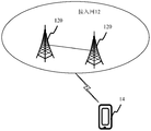
- Fig. 2 is a block diagram showing a communication system according to an exemplary embodiment
- Fig. 3 is a flow chart showing a method for power configuration in multi-bandwidth transmission according to an exemplary embodiment
- Fig. 4 is a flow chart showing a method for power configuration during multi-bandwidth transmission according to another exemplary embodiment
- Fig. 5 is a flowchart showing a method for power configuration in multi-bandwidth transmission according to another exemplary embodiment
- Fig. 6 is a flow chart showing a method for power configuration during multi-bandwidth transmission according to another exemplary embodiment
- Fig. 7 is a flowchart showing a method for power configuration during multi-bandwidth transmission according to another exemplary embodiment
- Fig. 8 is a flowchart showing a method for power configuration during multi-bandwidth transmission according to another exemplary embodiment
- Fig. 9 is a flow chart showing a method for power configuration in multi-bandwidth transmission according to another exemplary embodiment
- Fig. 10 is a block diagram showing a power configuration device in multi-bandwidth transmission according to an exemplary embodiment
- Fig. 11 is a block diagram showing a power configuration device during multi-bandwidth transmission according to another exemplary embodiment
- Fig. 12 is a schematic structural diagram of a terminal according to an exemplary embodiment
- Fig. 13 is a block diagram showing an access network device according to an exemplary embodiment.
- Multi-bandwidth transmission refers to the transmission method in which the terminal simultaneously uses more than two bandwidths to transmit uplink to the base station.
- multi-bandwidth transmission includes, but is not limited to, scenarios such as carrier aggregation scenarios and multiple uplink active bandwidth parts (Band With Part, BWP) and/or sub-band (Sub-band) configured to the terminal in the NR system.
- BWP Band With Part
- Sub-band sub-band
- Carrier aggregation It can refer to continuous carrier aggregation or discontinuous carrier aggregation. In the embodiments of the present disclosure, carrier aggregation refers to that the terminal uses two or more carriers in different frequency bands to jointly transmit signals to the base station.
- Uplink transmission time ratio (duty cycle): The ratio of the uplink transmission time to the total time (uplink transmission time + downlink reception time) in a subframe.
- the uplink transmit power of the terminal is classified according to the power class Power class.
- the transmit power of power level 3 is 23dBm (that is, decibel milliwatt).
- the transmission power of power level 2 is 26dBm.
- HPUE The terminal entering a higher power level than power level 3 is called HPUE.
- different power levels correspond to different power levels, and different power levels correspond to different SARs.
- SAR is an indicator that measures the amount of radiation to the human body when the terminal transmits wireless signals in terminal design.
- the OTA index corresponding to the SAR and the emission capability is a pair of contradictory indexes.
- the UE's emission capability needs to exceed the emission capability of the OTA index, but cannot exceed the radiation requirement of the SAR.
- HPUE will have the problem of SAR exceeding the standard, that is, when the power level is high, the cumulative radiation in a certain period of time may exceed the radiation requirement of SAR.
- the LTE, NR TDD or FDD bandwidth aggregation networking of different power levels may have different power levels for different bandwidths.
- the SAR value in certain time windows may exceed the standard, and the situation is more complicated; or, in Africa
- multiple bandwidths allocated to the terminal are all in the uplink transmission state, which may also cause the SAR value in some time windows to exceed the standard.
- LTE bandwidth, NR bandwidth A, and NR bandwidth B have their own uplink and downlink configurations.
- the terminal is in three Uplink transmission is being carried out on the bandwidth, at this time it is easy to cause the SAR to exceed the standard;
- the NR bandwidth B uses a high power level for uplink transmission, the transmit power on the NR bandwidth B during the time period of area 2 Superimposed with the transmit power on the LTE bandwidth, it is also easy to cause the SAR to exceed the standard; in another case, if the inspection is conducted in a larger time window, for example, the frame is the unit of the time window, the frame 3 in Figure 1 is due to the uplink configuration Too much can easily lead to excessive SAR.
- the present disclosure provides a power configuration method during multi-bandwidth transmission.
- the power value coordination between multiple bandwidths is performed in the scenario of multi-bandwidth transmission on n bandwidths, so as to control the uplink transmission power of the terminal to avoid SAR exceeding the standard .
- the equivalent power value of a single bandwidth is a value used to equivalently measure the power value of the terminal when it performs uplink transmission on a single bandwidth. This value can be used as a criterion for judging whether the SAR on a single bandwidth exceeds the standard.
- the calculation method of the equivalent power value of a single bandwidth Taking a single bandwidth as the j-th bandwidth as an example, the entire evaluation time window includes n time sub-windows, and the terminal uses correspondingly in the n time sub-windows on the j-th bandwidth.
- one power class corresponds to one uplink transmit power.
- the power of PC2 is 26dBm (ie, decibel milliwatt)
- the power of PC3 is 23dBm.
- the equivalent power value corresponding to the j-th bandwidth is equal to:
- P eq_Band_j is the equivalent power value of the j-th bandwidth under the designated duty cycle; DC as_j is the designated duty cycle corresponding to the j-th bandwidth; T window is the entire evaluation time window; DC pi is the i-th sub-evaluation time period P i is the power corresponding to the actual power level in the i-th sub-assessment period; T i is the i-th sub-assessment period, each sub-assessment period does not overlap each other, i is not greater than An integer of n.
- the actual power level in each sub-assessment period may be the same or different.
- the actual duty cycle in each sub-assessment period may be the same or different.
- the designated duty cycle corresponding to a single bandwidth is configured by the base station or determined in a predefined manner.
- the designated duty cycle corresponding to each bandwidth is the same or different.
- any one of the actual duty cycles used by the terminal in the j-th bandwidth can be used as the designated duty cycle; or, the smallest actual duty cycle used by the terminal in the j-th bandwidth
- the value is used as the designated duty cycle; or, the maximum value of the actual duty cycle used by the terminal in the j-th bandwidth is the designated duty cycle; or, the predefined duty cycle is determined as the designated duty cycle. For example, 50% is determined as the designated duty cycle, 75% is determined as the designated duty cycle, or 100% is determined as the designated duty cycle.
- Overall equivalent power value It is a value used to equivalently measure the power of the entire terminal for multi-bandwidth transmission over n bandwidths.
- the overall equivalent power value is calculated based on the equivalent power value corresponding to each bandwidth of the terminal in the n bandwidths. In a multi-bandwidth transmission scenario, this value can be used as a criterion for judging whether the SAR of the entire terminal exceeds the standard.
- the first calculation method of the overall equivalent power value For each of the n bandwidths, multiply the equivalent power value corresponding to the bandwidth, the designated duty cycle, and the evaluation time window to obtain the first product corresponding to the bandwidth ; Accumulate the first multipliers corresponding to the n bandwidths to obtain the overall equivalent power value. That is:
- P eq is the overall equivalent power value of the terminal, DC as is the designated duty cycle corresponding to the entire terminal, P eq_Band_j is the equivalent power value of bandwidth j under the designated uplink transmission time ratio DC as_j ; DC as_ j is bandwidth j The corresponding designated duty cycle; T window is the entire evaluation time window, and P eq_Band_j x DC as_ j x T window represents the first product.
- the second calculation method of the overall equivalent power value For each of the n bandwidths, multiply the equivalent power value corresponding to the bandwidth by the specified duty cycle to obtain the second product corresponding to the bandwidth; The bandwidth is respectively corresponding to the second multiplication and accumulation to obtain the overall equivalent power value. That is:
- P eq is the overall equivalent power value of the terminal, DC as is the designated duty cycle corresponding to the entire terminal, P eq_Band_j is the equivalent power value of bandwidth j under the designated uplink transmission time ratio DC as_j ; DC as_ j is bandwidth j The corresponding designated duty cycle; P eq_Band_j x DC as_j represents the second product.
- Fig. 2 is a block diagram of a communication system provided by an exemplary embodiment of the present disclosure.
- the communication system may be a 5G NR system.
- the communication system may include: an access network 12 and a terminal 14.
- the access network 12 includes several access network devices 120.
- the access network device 120 and the core network device 110 communicate with each other through a certain interface technology, such as the S1 interface in the LTE system, and the NG interface in the 5G NR system.
- the access network device 120 may be a base station, which is a device deployed in an access network to provide a wireless communication function for a terminal.
- the base station may include various forms of macro base stations, micro base stations, relay stations, access points, and so on.
- the names of devices with base station functions may be different. For example, in LTE systems, they are called eNodeB or eNB; in 5G NR systems, they are called gNodeB or gNB. As communication technology evolves, the description of the name "base station" may change.
- the terminal 14 may include various handheld devices with wireless communication functions, vehicle-mounted devices, wearable devices, computing devices or other processing devices connected to a wireless modem, as well as various forms of user equipment (UE), mobile stations ( Mobile Station, MS), terminal (English: terminal device), etc.
- UE user equipment
- MS Mobile Station
- terminal International: terminal device
- the access network device 120 and the terminal 14 communicate with each other through a certain air interface technology, such as a Uu interface.
- Fig. 3 is a flowchart of a method for power configuration during multi-bandwidth transmission according to an exemplary embodiment. This method can be executed by the communication system shown in FIG. 2. The method includes:
- Step 301 The base station determines the configuration upper limit of the overall equivalent power value when the terminal performs multi-bandwidth transmission on n bandwidths.
- the terminal uses n bandwidths for multi-bandwidth transmission, and n is an integer greater than 1.
- multi-bandwidth transmission on n bandwidths includes: multi-bandwidth transmission under carrier aggregation, and/or multi-bandwidth transmission under non-carrier aggregation.
- Multi-bandwidth transmission can also be referred to as: multi-bandwidth simultaneous transmission, multi-bandwidth coordinated transmission, multi-bandwidth coordinated transmission, and other possible descriptions, which are not limited in the present disclosure.
- the overall equivalent power value refers to the integration of n equivalent power values corresponding to the terminal's uplink transmission on n bandwidths into a power value under a specified duty cycle.
- the overall equivalent power value is calculated according to the equivalent power values respectively corresponding to the terminal on the n bandwidths.
- the configuration upper limit of the overall equivalent power value is a criterion for judging whether the SAR exceeds the standard.
- the configuration upper limit of the overall equivalent power value can be configured by the base station, and can also be reported by the terminal to the base station.
- Step 302 The base station generates configuration information of the first bandwidth among the n bandwidths for the terminal.
- the first bandwidth is the bandwidth that needs to be configured this time among the n bandwidths, and the first bandwidth is all or a part of the n bandwidths.
- the present disclosure does not limit the number of the first bandwidths.
- the base station generates configuration information of the first bandwidth for the terminal, and the configuration information is used to configure power configuration parameters when the terminal performs uplink transmission on the first bandwidth.
- the power configuration parameters include: power level and/or duty cycle.
- the base station generates configuration information of the first bandwidth in the n bandwidths for the terminal, and the overall equivalent power value on the n bandwidths corresponding to the configuration information is not higher than the above-mentioned configuration upper limit. That is, the overall equivalent power value of the terminal configured by the configuration information when performing uplink transmission on the n bandwidths is not higher than the above-mentioned configuration upper limit.
- Step 303 The base station sends configuration information to the terminal.
- the base station sends the generated configuration information of the first bandwidth to the terminal, where the configuration information is used to configure the power configuration parameters when the terminal performs uplink transmission on the first bandwidth.
- the configuration information includes configuration information of one or more first bandwidths, which is used to configure power configuration parameters when the terminal performs uplink transmission on the one or more first bandwidths.
- Step 304 The terminal receives the configuration information sent by the base station.
- Step 305 The terminal determines the power configuration parameter when performing uplink transmission on the first bandwidth according to the configuration information.
- the power configuration parameter includes at least one of a duty cycle when the terminal performs uplink transmission on the first bandwidth, and a power level when the terminal performs uplink transmission on the first bandwidth.
- the method provided in this embodiment integrates the equivalent power value of the terminal on n bandwidths into the overall equivalent power value of the entire terminal in a scenario where the terminal uses multi-bandwidth transmission.
- the configuration upper limit of the overall equivalent power value is used as the criterion for judging whether the SAR exceeds the standard, so that when the base station generates the configuration information of the first bandwidth of the n bandwidths to the terminal, it can perform reasonable configuration based on the uniform configuration upper limit of the overall equivalent power value , To ensure that the overall equivalent power value on the n bandwidths allocated to the terminal is not higher than the configuration upper limit, thereby reducing or avoiding the problem of SAR exceeding in certain time windows.
- the process of generating configuration information of the first bandwidth in n bandwidths by the base station for the terminal includes the following steps:
- Step 3021 The base station obtains the equivalent power value corresponding to each of the n bandwidths of the terminal.
- the base station may initially generate the first power value and the first duty cycle of the first bandwidth according to at least one factor such as service, coverage, power consumption, and antenna configuration.
- the first power value refers to the actual transmit power when the terminal performs uplink transmission on the first bandwidth.
- the equivalent power value corresponding to each of the n bandwidths can be calculated by the base station.
- the equivalent power value of the first bandwidth can be calculated by the base station; it can also be calculated by the terminal and reported to the base station.
- the equivalent power value of the second bandwidth outside the bandwidth may be calculated in advance by the terminal and reported to the base station. This embodiment does not limit this.
- Step 3022 Calculate the overall equivalent power value of the terminal according to the equivalent power value and the designated duty cycle corresponding to each bandwidth of the terminal.
- the base station After obtaining the corresponding equivalent power value and designated duty cycle for each bandwidth, the base station calculates the overall equivalent power value of the terminal according to Formula 2 or Formula 3.
- the designated uplink transmission time ratio DC as corresponding to the entire terminal in Formula 2 or Formula 3 is configured by the base station or determined in a predefined manner.
- any one of the actual duty cycles used by the terminal in n bandwidths can be used as the designated duty cycle; or, the minimum value of the actual duty cycles used by the terminal in n bandwidths can be used as the designated duty cycle; or , Take the maximum value of the actual duty cycles used by the terminal in the n bandwidths as the designated duty cycle; or, determine the predefined duty cycle as the designated duty cycle.
- Step 3023 Determine whether the overall equivalent power value is higher than the configuration upper limit.
- the base station predicts whether the SAR of the terminal will exceed the standard after this configuration.
- step 3024 is executed.
- step 3025 is executed.
- Step 3024 When the overall equivalent power value is not higher than the configuration upper limit, generate configuration information of the first bandwidth.
- the base station when the overall equivalent power value is not higher than the configuration upper limit, the base station generates configuration information of the first bandwidth according to the first duty cycle and/or the first power value of the first bandwidth. For example, according to the first duty cycle and the changed items in the first power value, the configuration information of the first bandwidth is generated.
- Step 3025 When the overall equivalent power value is higher than the configuration upper limit, regenerate configuration information of the first bandwidth.
- the base station When the overall equivalent power value is higher than the configuration upper limit, the base station reduces the first duty cycle and/or the first power value of the first bandwidth, and recalculates the overall equivalent power value of the terminal, and enters step 3023 again until the terminal.
- the configuration information of the first bandwidth is generated according to the first duty cycle and/or the first power value of the first bandwidth.
- the base station obtains the equivalent power value corresponding to each of the n bandwidths of the terminal, including the following two cases:
- the base station calculates each bandwidth according to the default duty cycle and preset power level corresponding to each of the n bandwidths.
- the terminal when the terminal has connected to the network and uses multiple bandwidths for uplink transmission, due to changes in at least one factor such as service, coverage, power consumption, antenna configuration, etc., all or part of the first bandwidth power exists in the n bandwidths Configuration parameters need to be adjusted.
- the base station adjusts the first duty cycle and/or first power value of the first bandwidth according to the adjustment requirement, and according to the adjusted first duty cycle and/or first power value of the first bandwidth.
- a power value recalculate the equivalent power value corresponding to the first bandwidth.
- the base station When the first bandwidth is a part of n bandwidths, the base station also needs to obtain the equivalent power value corresponding to the second bandwidth other than the first bandwidth in the n bandwidths.
- the base station obtains the second duty cycle and the second power value of the second bandwidth other than the first bandwidth among the n bandwidths, and the base station calculates the second duty cycle and the second power value according to the second duty cycle and the second power value. 2.
- the equivalent power value corresponding to the bandwidth For example, the base station reads the second duty cycle and the second power value of the second bandwidth in the history buffer, or the base station receives the second duty cycle and the second power value of the second bandwidth reported by the terminal.
- the second power value is the actual power when the terminal performs uplink transmission on the second bandwidth.
- the base station obtains the equivalent power value corresponding to the second bandwidth other than the first bandwidth among the n bandwidths. For example, the base station reads the equivalent power value of the second bandwidth in the history buffer, or the base station receives the equivalent power value of the second bandwidth reported by the terminal.
- the base station After obtaining the equivalent power value corresponding to the first bandwidth and the equivalent power value corresponding to the second bandwidth, the base station calculates the overall equivalent power value of the terminal according to Formula 2 or Formula 3 to further determine whether the overall equivalent power value is higher than Configure the upper limit.
- the base station when the overall equivalent power value is higher than the configuration upper limit, in addition to regenerating the configuration information of the first bandwidth, the base station may also lower the second bandwidth of the second bandwidth.
- Two duty cycle and/or second power value For example: the terminal uses bandwidth A, bandwidth B, and bandwidth C for uplink transmission at the same time.
- the power configuration parameters corresponding to bandwidth A need to be increased due to business requirements, if the adjusted overall equivalent power value is higher than the configuration upper limit , The base station can lower the bandwidth B and/or bandwidth C corresponding power configuration parameters.
- the base station calculates the equivalent power value corresponding to the second bandwidth according to the second duty cycle and the second power value of the adjusted second bandwidth; according to the equivalent power value corresponding to the first bandwidth and the equivalent power corresponding to the second bandwidth Calculate the overall equivalent power value.
- the power configuration parameter of the second bandwidth that has been adjusted down has changed, and therefore the second bandwidth that has been down adjusted has also become the first bandwidth that needs to be configured this time.
- the base station since the process of adjusting the second bandwidth cannot be an infinite number of times, the base station also stores a preset number of times, and the preset number of times is used to avoid multiple invalidation of the second bandwidth. Turn down. As shown in Figure 5, the base station decides to continue to adjust or refuse to adjust the second bandwidth according to the preset times, and the steps are as follows:
- Step 11 Determine whether the number of adjustments is higher than the preset number.
- a preset number of times is stored in the base station, and the preset number is used to instruct the base station to adjust the second duty cycle and/or the upper limit of the second power value of the second bandwidth.
- the base station determines whether the number of times of lowering the second bandwidth is higher than the preset number.
- step 14 is executed; otherwise, step 12 is returned to.
- Step 12 Adjust the second duty cycle and/or the second power value of the second bandwidth.
- the base station reduces the second duty cycle when the terminal performs uplink transmission on the second bandwidth.
- the base station lowers the second power value when the terminal performs uplink transmission on the second bandwidth.
- the base station simultaneously reduces the second duty cycle and the second power value when the terminal performs uplink transmission on the second bandwidth.
- Step 13 Calculate the overall equivalent power value of the terminal according to the second duty cycle and/or the second power value of the adjusted second bandwidth.
- the base station After recalculating the overall equivalent power value of the terminal, the base station executes step 3023 again.
- Step 14 The base station refuses to adjust the second duty cycle and/or the second power value of the second bandwidth.
- the base station may cancel this configuration.
- the method provided in this embodiment reduces the second duty cycle and/or the second power value of the second bandwidth to ensure the overall equivalent power of the terminal while ensuring the normal configuration of the first bandwidth.
- the value is not higher than the upper limit of the configuration to avoid exceeding the SAR limit in certain time windows.
- the method provided in this embodiment controls the time required for the configuration of the base station by limiting the upper limit of the number of adjustments, ensuring that the terminal can obtain the configuration information of the base station in time, thereby ensuring the delay requirement when the terminal performs uplink transmission.
- the service priority of all or part of the second bandwidth may become higher, that is, there is the second bandwidth.
- the service priority of is higher than the service priority of the first bandwidth.
- the second bandwidth with a lower service priority is preferentially selected for lowering.
- all the service priorities of the second bandwidth are higher than the service priorities of the first bandwidth, and the following adjustment methods may also be adopted:
- the first duty cycle and/or the first equivalent power of the first bandwidth is reduced value.
- the base station recalculates the overall equivalent power value according to the first duty cycle and/or the first equivalent power value of the reduced first bandwidth, and when the overall equivalent power value is not higher than the configuration upper limit, according to the first bandwidth of the first bandwidth
- a duty cycle and/or a first power value generates configuration information of the first bandwidth.
- the base station when determining whether the SAR of the terminal exceeds the standard, the overall equivalent power value of the terminal is used for calculation. In some optional embodiments, when the overall equivalent power value is calculated for the first time, the base station may calculate the remaining equivalent power value quota. When it is necessary to determine whether the SAR of the terminal exceeds the standard, it is only necessary to calculate whether the adjusted incremental power value is higher than the remaining equivalent power value. Referring to Figure 6, the process may include the following steps:
- Step 21 When the overall equivalent power value is not higher than the configuration upper limit, the remaining equivalent power value quota is calculated according to the configuration upper limit and the overall equivalent power value.
- the remaining equivalent power value quota (configuration upper limit-the overall equivalent power value of the terminal). That is, when the overall equivalent power value is not higher than the configuration upper limit, the base station will cooperate with the upper limit to subtract the overall equivalent power value to obtain the remaining equivalent power value quota.
- Step 22 When the third duty cycle and the third power value of the third bandwidth need to be adjusted, adjust at least one of the third duty cycle and the third power value of the third bandwidth according to the adjustment requirement.
- the adjustment requirement includes at least one of service, coverage area, power consumption, and antenna configuration.
- the base station adjusts the third duty cycle and/or the third power value of the third bandwidth according to at least one of the foregoing adjustment requirements.
- the third power value is the actual power when the terminal performs uplink transmission on the third bandwidth.
- the third duty cycle and/or the third power value of the third bandwidth it may be adjusted to be higher or lower.
- Step 23 According to the third duty cycle and/or the third power value of the third bandwidth, the increment of the equivalent power value of the third bandwidth is calculated.
- the increment (the equivalent power value of the third bandwidth after this adjustment-the equivalent power value of the third bandwidth before this adjustment).
- Step 24 When the increment of the equivalent power value of the third bandwidth is not higher than the remaining equivalent power value quota, generate configuration information of the third bandwidth.
- the relationship between the calculation time of the remaining equivalent power value quota and the calculation time of the increment is not limited. The above two calculations can be performed at the same time, or the remaining equivalent power value quota can be calculated first and then the second calculation time.
- the increment of the equivalent power value of the third bandwidth it is also possible to calculate the increment of the equivalent power value of the third bandwidth first, and then calculate the remaining equivalent power value quota.
- the base station determines whether the SAR value of the terminal exceeds the standard by calculating and comparing the increment of the equivalent power value of the third bandwidth with the remaining equivalent power value quota, without recalculating the overall
- the equivalent power value simplifies the calculation and reduces the calculation amount of the base station.
- step 301 may adopt any one of the following three implementation modes:
- the base station receives the configuration upper limit of the overall equivalent power value reported by the terminal, and the configuration upper limit is calculated by the terminal according to the configuration upper limit of the equivalent power value of each bandwidth;
- the base station receives the upper limit of the sub-configuration of the equivalent power value of each bandwidth reported by the terminal, and the base station determines the upper limit of the overall equivalent power value of the terminal according to the upper limit of the sub-configuration;
- the base station receives the first sub-configuration upper limit when each bandwidth reported by the terminal works independently under a specified duty cycle, and determines the configuration upper limit of the overall equivalent power value of the terminal according to the first sub-configuration upper limit.
- the terminal first calculates the configuration upper limit of the overall equivalent power value, and then the terminal reports the configuration upper limit of the overall equivalent power value to the base station.
- the process can include the following steps:
- Step 30101 The terminal obtains the upper limit of the first sub-configuration of the power value of each of the n bandwidths when working independently under a specified duty cycle.
- step 30102 the terminal determines the upper limit of the second sub-configuration when each bandwidth is used for multi-bandwidth transmission according to the upper limit of the first sub-configuration of the power value of each bandwidth when working independently under the specified duty cycle.
- the upper limit of the second sub-configuration is smaller than the upper limit of the first sub-configuration. That is, the upper limit of the second sub-configuration needs to be rolled back to a certain extent relative to the upper limit of the first sub-configuration.
- the terminal calculates the average value of the first sub-configuration upper limit of the equivalent power values of n bandwidths when independently working under the corresponding duty cycle, and determines the quotient of the average value and n as each bandwidth The upper limit of the second sub-configuration for multi-bandwidth transmission;
- the quotient of 90 and 3 is determined as 30 as the upper limit of the second sub-configuration for multi-bandwidth transmission for each bandwidth.
- the terminal calculates the maximum value of the first sub-configuration upper limit of the equivalent power values of n bandwidths when independently working under the corresponding duty cycle, and determines the quotient of the maximum value and n as each bandwidth The upper limit of the second sub-configuration for multi-bandwidth transmission;
- the upper limit of the first sub-configuration of bandwidth D is 80%
- the upper limit of the first sub-configuration of bandwidth E is 90%
- the upper limit of the first sub-configuration of bandwidth F is 60%
- the upper limit of the first sub-configuration of bandwidth E among the three bandwidths Maximum, the quotient of 90% and 3, 30%, is determined as the upper limit of the second sub-configuration for each bandwidth for multi-bandwidth transmission.
- the terminal calculates the minimum value of the first sub-configuration upper limit of the equivalent power values of n bandwidths when they work independently under the corresponding duty cycle, and determines the quotient of the minimum value and n as each bandwidth The upper limit of the second sub-configuration for multi-bandwidth transmission;
- the upper limit of the first sub-configuration of bandwidth D is 80%
- the upper limit of the first sub-configuration of bandwidth E is 90%
- the upper limit of the first sub-configuration of bandwidth F is 60%
- the upper limit of the first sub-configuration of bandwidth F among the three bandwidths The smallest, the quotient of 60% and 3, 20%, is determined as the upper limit of the second sub-configuration for each bandwidth for multi-bandwidth transmission.
- the terminal calculates the average value of the first sub-configuration upper limit of the equivalent power value of the n bandwidths when working independently under the corresponding duty cycle, and divides the average value into n weights.
- the division value is determined as the upper limit of the second sub-configuration when the n bandwidths are used for multi-bandwidth transmission, the n weights correspond to the n bandwidths one-to-one, and the sum of the n weights is 1;
- the upper limit of the first sub-configuration of the bandwidth M and the bandwidth N is 80%, and the weight of the two bandwidths is 0.5. If 80% is divided according to the weight, the second sub-configuration of the bandwidth M and the bandwidth N is used for multi-bandwidth transmission.
- the upper limit of the configuration is 40%.
- the size of the n weights can be set according to at least one factor such as service priority, power consumption, coverage, and antenna configuration on each bandwidth.
- the terminal calculates the maximum value of the first sub-configuration upper limit of the equivalent power value when the n bandwidths work independently under the corresponding duty cycle, and divides the maximum value according to n weights.
- the division value is determined as the upper limit of the second sub-configuration when the n bandwidths are used for multi-bandwidth transmission, the n weights correspond to the n bandwidths one-to-one, and the sum of the n weights is 1;
- the upper limit of the first sub-configuration of bandwidth Q is both 50%
- the upper limit of the first sub-configuration of bandwidth U is both 70%
- the upper limit of the first sub-configuration of bandwidth V is both 90%
- the weight of bandwidth Q is 0.3
- the upper limit of bandwidth U is
- the weight of the bandwidth V is 0.5
- the weight of the bandwidth V is 0.2.
- the upper limit of the first sub-configuration of the bandwidth V is the largest
- the upper limit of the second sub-configuration of the bandwidth Q for multi-bandwidth transmission is 27%.
- the upper limit of the second sub-configuration is 45%
- the upper limit of the second sub-configuration when the bandwidth V performs multi-bandwidth transmission is 18%.
- the terminal calculates the minimum value of the first sub-configuration upper limit of the equivalent power values of n bandwidths when working independently under the corresponding duty cycle, and divides the minimum values into n weights.
- the division value is determined as the upper limit of the second sub-configuration when n bandwidths are used for multi-bandwidth transmission, the n weights correspond to the n bandwidths one-to-one, and the sum of the n weights is 1.
- the upper limit of the first sub-configuration of bandwidth Q is both 50%
- the upper limit of the first sub-configuration of bandwidth U is both 70%
- the upper limit of the first sub-configuration of bandwidth V is both 90%
- the weight of bandwidth Q is 0.3
- the upper limit of bandwidth U is
- the weight of the bandwidth V is 0.5
- the weight of the bandwidth V is 0.2.
- the upper limit of the first sub-configuration of bandwidth Q is the smallest
- the upper limit of the second sub-configuration of bandwidth Q for multi-bandwidth transmission is 15%.
- the upper limit of the second sub-configuration is 25%
- the upper limit of the second sub-configuration when the bandwidth V performs multi-bandwidth transmission is 10%.
- Step 30103 The terminal determines the configuration upper limit of the overall equivalent power value according to the second sub-configuration upper limit and the designated duty cycle when performing multi-bandwidth transmission for each bandwidth.
- the second sub-configuration upper limit when the terminal performs multi-bandwidth transmission and the designated uplink transmission time ratio DC As_j is multiplied by the evaluation time window to obtain the third product corresponding to the bandwidth; the third product corresponding to n bandwidths is accumulated and added to obtain the configuration upper limit of the overall equivalent power value.
- the overall equivalent power value is calculated by formula 3, based on a similar calculation principle, for each of the n bandwidths, the second sub-configuration upper limit when the bandwidth is multi-bandwidth transmission and the designated uplink transmission time ratio DC as_j , The fourth product corresponding to the bandwidth is obtained; the fourth product corresponding to the n bandwidths is accumulated and added to obtain the configuration upper limit of the overall equivalent power value.
- Step 30104 The terminal reports the configuration upper limit of the overall equivalent power value to the base station.
- Step 30105 The base station receives and saves the configuration upper limit of the overall equivalent power value reported by the terminal.
- the terminal calculates and reports the second sub-configuration upper limit to the base station, and then the base station calculates the configuration upper limit of the overall equivalent power value.
- the process can include the following steps:
- Step 30106 The terminal reports to the base station the upper limit of the second sub-configuration under the specified duty cycle of each of the n bandwidths.
- Step 30107 The base station receives the second sub-configuration upper limit of each of the n bandwidths reported by the terminal under the specified duty cycle.
- Step 30108 The base station determines the configuration upper limit of the overall equivalent power value according to the second sub-configuration upper limit of each bandwidth under the specified duty cycle.
- the base station calculates the configuration upper limit of the overall equivalent power value according to Formula 2 or Formula 3. For the calculation process, refer to step 30103, which will not be repeated here.
- the base station calculates the configuration upper limit of the overall equivalent power value.
- the process can include the following steps:
- Step 30109 The terminal reports to the base station the upper limit of the first sub-configuration of the power value of each of the n bandwidths when independently working under a specified duty cycle.
- Step 30110 The base station receives the first sub-configuration upper limit of the power value of each of the n bandwidths reported by the terminal when it independently works under a specified duty cycle.
- the base station determines the upper limit of the second sub-configuration when each bandwidth is used for multi-bandwidth transmission according to the upper limit of the first sub-configuration of the power value when each bandwidth works independently under the specified duty cycle.
- the upper limit of the second sub-configuration is smaller than the upper limit of the first sub-configuration.
- the base station calculates the average value of the first sub-configuration upper limit of the equivalent power values of n bandwidths when they work independently at the corresponding power level, and determines the quotient of the average value and n as each bandwidth The upper limit of the second sub-configuration for multi-bandwidth transmission;
- the base station calculates the maximum value of the first sub-configuration upper limit of the equivalent power values of n bandwidths when they work independently at the corresponding power level, and determines the quotient of the maximum value and n as each The second sub-configuration upper limit when the bandwidth is used for multi-bandwidth transmission;
- the base station calculates the minimum value of the first sub-configuration upper limit of the equivalent power values of n bandwidths when they work independently at the corresponding power level, and determines the quotient of the minimum value and n as each The second sub-configuration upper limit when the bandwidth is used for multi-bandwidth transmission;
- the base station calculates the average value of the first sub-configuration upper limit of the equivalent power values of n bandwidths when they work independently at the corresponding power level, and divides the average value according to n weights.
- the division values are determined as the upper limit of the second sub-configuration when the n bandwidths are used for multi-bandwidth transmission, the n weights correspond to the n bandwidths one-to-one, and the sum of the n weights is 1;
- the base station calculates the maximum value of the first sub-configuration upper limit of the equivalent power values of the n bandwidths when they work independently at the corresponding power level, and divides the maximum value into n weights.
- the division values are determined as the upper limit of the second sub-configuration when the n bandwidths are used for multi-bandwidth transmission, the n weights correspond to the n bandwidths one-to-one, and the sum of the n weights is 1;
- the base station calculates the minimum value of the first sub-configuration upper limit of the equivalent power values of n bandwidths when they work independently at the corresponding power level, and divides the minimum value into n weights.
- the two division values are determined as the upper limit of the second sub-configuration when the n bandwidths are used for multi-bandwidth transmission, the n weights correspond to the n bandwidths one-to-one, and the sum of the n weights is 1.
- Step 30112 The base station determines the configuration upper limit of the overall equivalent power value according to the second sub-configuration upper limit and the designated duty cycle when performing multi-bandwidth transmission for each bandwidth.
- the second sub-configuration upper limit when the base station performs multi-bandwidth transmission and the designated uplink transmission time ratio DC As_j is multiplied by the evaluation time window to obtain the third product corresponding to the bandwidth; the third product corresponding to n bandwidths is accumulated and added to obtain the configuration upper limit of the overall equivalent power value.
- the overall equivalent power value is calculated using formula 3, based on similar calculation principles, for each of the n bandwidths, the second sub-configuration upper limit when the base station performs multi-bandwidth transmission and the designated uplink transmission time ratio DC as_j , the fourth product corresponding to the bandwidth is obtained; the fourth product corresponding to the n bandwidths is accumulated and added to obtain the configuration upper limit of the overall equivalent power value.
- the equivalent power value of the foregoing single bandwidth can also be calculated from the equivalent duty cycle of the single bandwidth.
- the overall equivalent power value of the terminal can also be calculated from the overall equivalent duty cycle of the terminal.
- the equivalent duty cycle of a single bandwidth is a value used to equivalently measure the duty cycle of the terminal when it performs uplink transmission on a single bandwidth. This value can be used as a criterion for judging whether the SAR on a single bandwidth exceeds the standard.
- the calculation method of the equivalent duty cycle of a single bandwidth Taking a single bandwidth as the j-th bandwidth as an example, the entire evaluation time window includes n time sub-windows, and the terminal uses correspondingly in the n time sub-windows on the j-th bandwidth.
- n duty cycles and n power levels Among them, one power class (Power Class, PC) corresponds to one uplink transmit power.
- the power of PC2 is 26dBm (ie, decibel milliwatt)
- the power of PC3 is 23dBm.
- the equivalent duty cycle corresponding to the j-th bandwidth is equal to:
- DC eq_Band_j (DC p1 x P 1 x T 1 +DC p2 x P 2 x T 2 +DC p3 x P 3 x T 3 +...+DC pi x P i xT i +...+DC pn x P n x T n )/(P as_j x T window ); formula four
- DC eq_Band_j is the equivalent duty cycle of the j-th bandwidth at the specified power level; P as_j is the transmit power of the specified power level corresponding to the j-th bandwidth; T window is the entire evaluation time window; DC pi is the i-th band the actual duty cycle evaluation time period; actual power level P i is the power corresponding to the i-th piece of evaluation period; T i is the i-th evaluation period, do not overlap between each of the sub-evaluation period, i Is an integer not greater than n.
- the actual power level in each sub-assessment period may be the same or different.
- the designated power level corresponding to a single bandwidth is configured by the base station or determined in a predefined manner.
- the specified power level corresponding to each bandwidth is the same or different.
- any one of the actual power levels used by the terminal in the j-th bandwidth can be used as the designated power level; or, the minimum of the actual power levels used by the terminal in the j-th bandwidth
- the level is regarded as the designated power level; or, the largest level among the actual power levels used by the terminal in the j-th bandwidth is regarded as the designated power level; or, the predefined power level is determined as the designated power level.
- Overall equivalent duty cycle is a value used to equivalently measure the duty cycle when the entire terminal performs multi-bandwidth transmission on n bandwidths.
- the overall equivalent duty cycle is calculated based on the equivalent duty cycle corresponding to each bandwidth of the terminal on the n bandwidths. In a multi-bandwidth transmission scenario, this value can be used as a criterion for judging whether the SAR of the entire terminal exceeds the standard.
- the first calculation method of the overall equivalent duty cycle For each of the n bandwidths, multiply the equivalent duty cycle corresponding to the bandwidth, the specified power value, and the evaluation time window to obtain the first product corresponding to the bandwidth ; Accumulate the first multiplications corresponding to the n bandwidths to obtain the overall equivalent duty cycle. That is:
- DC eq (DC eq_Band_1 x P as_1 x T window +DC eq_Band_2 x P as_2 x T window +DC eq_Band_3 x P as_3 x T window +...+DC eq_Band_j x P as_j x T window +...DC eq_Band_n x P as_n x T window )/(P as x T window ); formula five
- DC eq is the overall equivalent duty cycle of the terminal, P as is the designated power value corresponding to the entire terminal, the designated power value corresponds to the designated power level, and DC eq_Band_j is the equivalent duty cycle of bandwidth j under the designated power value P as_j ; P as_j is the specified power value corresponding to bandwidth j; T window is the entire evaluation time window, and DC eq_Band_j x P as_j x T window represents the first product.
- the second calculation method for the overall equivalent duty cycle For each of the n bandwidths, multiply the equivalent duty cycle corresponding to the bandwidth by the specified power value to obtain the second product corresponding to the bandwidth;
- the bandwidths respectively correspond to the second multiplication accumulation and addition to obtain the overall equivalent duty cycle. That is:
- DC eq (DC eq_Band_1 x P as_1 + DC eq_Band_2 x P as_2 + DC eq_Band_3 x P as_3 +...+DC eq_Band_j x P as_j +...DC eq_Band_n x P as_n )/Pas; formula six
- DC eq is the overall equivalent duty cycle of the terminal, P as is the designated power value corresponding to the entire terminal, the designated power value corresponds to the designated power level, and DC eq_Band_j is the equivalent duty cycle of bandwidth j under the designated power value P as_j ; P as_j is the designated power value corresponding to bandwidth j, and DC eq_Band_j x P as_j represents the second product.
- the specified power value P as and the specified duty cycle (DC as ) are determined, and the overall equivalent duty cycle (DC eq ) and the overall equivalent power value (P eq ) can correspond to each other.
- Equation 8 The conversion principle of Equation 8 is the same as that of Equation 7, which determines the specified power value P as_j of the j-th bandwidth among n bandwidths and the specified uplink transmission time ratio DC as_j , and the equivalent uplink transmission time ratio DC of the j-th bandwidth eq_Band_j and the equivalent power value P eq_Band_j can correspond to each other.
- the base station or terminal can calculate the equivalent duty cycle of a single bandwidth through formula 4, and then calculate the equivalent power value of a single bandwidth through formula 7;
- the base station or terminal can directly calculate the overall equivalent duty cycle of the terminal through formula 4 and formula 5/6, and then calculate the overall equivalent power value of the terminal through formula 8;
- the base station or terminal can calculate the equivalent duty cycle of a single bandwidth by formula 4, and then calculate the equivalent power value of the single bandwidth by formula 7; the base station or terminal can calculate the overall equivalent duty cycle of the terminal by formula 5/6.
- Fig. 10 shows a block diagram of a power configuration device for multi-bandwidth transmission according to an exemplary embodiment of the present disclosure.
- the device can be implemented as all or part of the access network equipment through software, hardware or a combination of the two.
- the device includes: a processing module 420 and a sending module 440;
- the processing module 420 is configured to determine the configuration upper limit of the overall equivalent power value when the terminal performs multi-bandwidth transmission on n bandwidths, where n is an integer greater than 1.
- the processing module 420 is configured to generate configuration information of the first bandwidth in the n bandwidths for the terminal, and the overall equivalent power value in the n bandwidths corresponding to the configuration information is not higher than the configuration upper limit;
- the sending module 440 is configured to send configuration information to the terminal, and the above-mentioned configuration information is used to configure power configuration parameters when the terminal performs uplink transmission on the first bandwidth.
- the processing module 420 includes:
- the first processing submodule 4201 is configured to obtain the equivalent power value corresponding to each of the n bandwidths of the terminal, where the n bandwidths include the first bandwidth configured this time;
- the second processing sub-module 4202 is configured to calculate the overall equivalent power value of the terminal according to the equivalent power value corresponding to each bandwidth of the terminal and the duty cycle of the designated uplink transmission time;
- the third processing submodule 4203 is configured to generate configuration information of the first bandwidth when the overall equivalent power value is not higher than the configuration upper limit, and the configuration information of the first bandwidth is used to configure the first bandwidth of the terminal on the first bandwidth. Power value and/or first duty cycle.
- the second processing submodule 4202 is configured to, for each of the n bandwidths, multiply the equivalent power value corresponding to the bandwidth, the designated duty cycle, and the evaluation time window to obtain the first bandwidth corresponding to the bandwidth.
- One product accumulate and add the first multiplications corresponding to each of the n bandwidths to obtain the overall equivalent power value; or, for each of the n bandwidths, multiply the equivalent power value corresponding to the bandwidth by the specified duty cycle to get The second product corresponding to the bandwidth; the second product corresponding to the n bandwidths is accumulated and added to obtain the overall equivalent power value.
- the equivalent power value corresponding to the j-th bandwidth is equal to:
- P eq_Band_j (DC p1 x P 1 x T 1 +DC p2 x P 2 x T 2 +DC p3 x P 3 x T 3 +...+DC pi x P i x T i +...DC pn x P n x T n )/(DC as_j x T window );
- P eq_Band_j is the equivalent power value of the j-th bandwidth under the designated duty cycle
- DC as_j is the corresponding designated duty cycle of the j-th bandwidth
- T window is the entire evaluation time window
- DC pi is the i-th sub-evaluation time duty cycle within a segment
- the time period P i is to assess the actual power level corresponding to the power of the i-th piece
- T i is the i-th evaluation period, do not overlap between each of the sub-evaluation period.
- the first processing sub-module 4201 is configured to calculate the equivalent power value corresponding to each bandwidth according to the default duty cycle and the preset power value corresponding to each of the n bandwidths.
- the first processing submodule 4201 is configured to adjust the first power value and the first duty cycle of the first bandwidth according to the adjustment requirement when the first power value and the first duty cycle of the first bandwidth need to be adjusted. At least one of the cycles, the equivalent power value corresponding to the first bandwidth is calculated according to the first power value and the first duty cycle;
- the first processing submodule 4201 is configured to obtain the second power value and the second duty cycle of the second bandwidth excluding the first bandwidth among the n bandwidths, and calculate the second power cycle according to the second power value and the second duty cycle.
- the processing module 420 includes:
- the fourth processing submodule 4204 is configured to reduce the second power value of the second bandwidth and/or the second duty cycle when the overall equivalent power value is higher than the configuration upper limit.
- the processing module 420 includes:
- the fifth processing submodule 4205 is configured to reject the second power value of the second bandwidth and/or the second duty cycle when the number of times of adjustment is higher than the preset number and the overall equivalent power value is still higher than the configured upper limit. Adjustment.
- the processing module 420 includes:
- the sixth processing submodule 4206 is configured to lower the first bandwidth of the first bandwidth when the overall equivalent power value is higher than the configuration upper limit, and there is a service priority of the second bandwidth higher than the service priority of the first bandwidth Effective power value and/or first duty cycle.
- the device further includes:
- the processing module 420 is configured to calculate the remaining equivalent power value quota according to the configuration upper limit and the overall equivalent power value when the overall equivalent power value is not higher than the configuration upper limit;
- the processing module 420 is configured to adjust at least one of the third power value and the third duty cycle of the third bandwidth according to the adjustment requirement when the equivalent power value and the duty cycle of the third bandwidth need to be adjusted;
- the processing module 420 is configured to calculate the increment of the equivalent power value of the third bandwidth according to the third power value of the third bandwidth and/or the third duty cycle;
- the processing module 420 is configured to generate configuration information of the third bandwidth when the increment of the equivalent power value of the third bandwidth is not higher than the remaining equivalent power value quota, and the configuration information of the uplink transmit power is used to configure the terminal The third power value and/or the third duty cycle on the third bandwidth.
- the device further includes a receiving module 460;
- the receiving module 460 is configured to receive the configuration upper limit of the overall equivalent power value reported by the terminal.
- the receiving module 460 is configured to receive the upper limit of the second sub-configuration when each of the n bandwidths reported by the terminal performs multi-bandwidth transmission under a designated duty cycle;
- the processing module 420 is configured to determine the configuration upper limit of the overall equivalent power value according to the second sub-configuration upper limit when multi-bandwidth transmission is performed for each bandwidth in a designated duty cycle.
- the processing module 420 is configured to multiply the second sub-configuration upper limit, the specified duty cycle, and the evaluation time window for each bandwidth for multi-bandwidth transmission under the specified duty cycle to obtain the third product; The third product is added to determine the configuration upper limit of the overall equivalent power value.
- the processing module 420 is configured to obtain the fourth product by adding the second sub-configuration upper limit for the multi-bandwidth transmission under the designated duty cycle and the designated duty cycle for each bandwidth; add the fourth product to determine the overall equivalent The configuration upper limit of the power value;
- the receiving module 460 is configured to receive the first sub-configuration upper limit when each of the n bandwidths reported by the terminal works independently under a specified duty cycle;
- the processing module 420 is configured to determine the upper limit of the second sub-configuration for each bandwidth for multi-bandwidth transmission according to the upper limit of the first sub-configuration when each bandwidth works independently under a specified duty cycle. Sub-configuration upper limit;
- the processing module 420 is configured to determine the configuration upper limit of the overall equivalent power value according to the designated duty cycle and the second sub-configuration upper limit when performing multi-broadband transmission for each bandwidth.
- the processing module 420 includes:
- the seventh processing sub-module 4207 is configured to calculate the average value of the upper limit of the first sub-configuration of the equivalent power values of the n bandwidths when they work independently at the corresponding power level, and determine the quotient of the average value and n as each bandwidth The upper limit of the second sub-configuration for multi-bandwidth transmission;
- the seventh processing sub-module 4207 is configured to calculate the maximum value of the first sub-configuration upper limit of the equivalent power values of n bandwidths when independently working at the corresponding power level, and determine the quotient of the maximum value and n as every The upper limit of the second sub-configuration for multi-bandwidth transmission of two bandwidths;
- the seventh processing sub-module 4207 is configured to calculate the minimum value of the first sub-configuration upper limit of the equivalent power values of n bandwidths when they work independently at the corresponding power level, and determine the quotient of the minimum value and n as every The upper limit of the second sub-configuration for multi-bandwidth transmission with one bandwidth;
- the seventh processing sub-module 4207 is configured to calculate the average value of the first sub-configuration upper limit of the equivalent power values of n bandwidths when they work independently at the corresponding power level, and divide the average value according to n weights.
- the n division values are determined as the upper limit of the second sub-configuration when the n bandwidths are used for multi-bandwidth transmission, the n weights correspond to the n bandwidths one-to-one, and the sum of the n weights is 1;
- the seventh processing sub-module 4207 is configured to calculate the maximum value of the first sub-configuration upper limit of the equivalent power values of n bandwidths when they work independently at the corresponding power level, and divide the maximum value according to n weights
- the n division values are determined as the upper limit of the second sub-configuration when the n bandwidths are used for multi-bandwidth transmission, the n weights correspond to the n bandwidths one-to-one, and the sum of the n weights is 1;
- the seventh processing sub-module 4207 is configured to calculate the minimum value of the first sub-configuration upper limit of the equivalent power values of n bandwidths when they work independently at the corresponding power level, and divide the minimum value according to n weights
- the n division values are determined as the upper limit of the second sub-configuration when the n bandwidths are used for multi-bandwidth transmission, the n weights correspond to the n bandwidths one-to-one, and the sum of the n weights is 1.
- the power configuration device for multi-bandwidth transmission uses a processing module to determine the upper limit of the configuration of the overall equivalent power value when the terminal performs multi-bandwidth transmission on n bandwidths, where n is an integer greater than 1. ; Generate the configuration information of the first bandwidth in the n bandwidths for the terminal, the overall equivalent power value on the n bandwidths corresponding to the above configuration information is not higher than the configuration upper limit, the overall equivalent power value is based on the terminal in n The corresponding equivalent power value on the bandwidth is calculated; and then the configuration information is sent to the terminal through the sending module, and the above configuration information is used to configure the power configuration parameters when the terminal performs uplink transmission on the first bandwidth.
- the device adapts the power value of the terminal so that the overall equivalent power value of the n bandwidth allocated to the terminal is not higher than the upper limit of the configuration, avoiding the corresponding SAR The value exceeds the standard.
- Fig. 11 shows a block diagram of a power configuration device for multi-bandwidth transmission according to an exemplary embodiment of the present disclosure.
- the device can be implemented as all or part of the terminal through software, hardware or a combination of the two.
- the device includes: a receiving module 560 and a processing module 520;
- the receiving module 560 is configured to receive configuration information sent by the base station, and the overall equivalent power value on the n bandwidths of the multi-bandwidth transmission corresponding to the configuration information is not higher than the configuration upper limit;
- the processing module 520 is configured to determine the power configuration parameters for uplink transmission on the first bandwidth according to the configuration information.
- the first bandwidth is one or more of the n bandwidths when the terminal transmits in multiple bandwidths.
- the overall equivalent uplink transmission time ratio duty cycle is not higher than the configured upper limit.
- the device further includes:
- the sending module 540 is configured to report the configuration upper limit of the overall equivalent power value to the base station;
- the sending module 540 is configured to report to the base station the upper limit of the second sub-configuration when each of the n bandwidths performs multi-bandwidth transmission under a specified duty cycle;
- the sending module 540 is configured to report to the base station the first sub-configuration upper limit of the power value of each of the n bandwidths when operating independently under a specified duty cycle.
- the device further includes:
- the processing module 520 is configured to calculate the upper limit of the sub-power value corresponding to the j-th broadband in the i-th sub-evaluation time period, the corresponding duty cycle, and the corresponding i-th sub-evaluation time period of the n bandwidth The upper limit of the second sub-configuration for each bandwidth under the specified duty cycle.
- the power configuration device for multi-bandwidth transmission receives configuration information sent by the base station through the receiving module, and the overall equivalent power value on the n bandwidths of multi-bandwidth transmission corresponding to the configuration information is not high.
- the overall equivalent power value is calculated according to the equivalent power values corresponding to the terminal on the n bandwidths, and the processing module determines the power configuration parameters for uplink transmission on the first bandwidth according to the configuration information.
- the device adapts the power value of the terminal according to the configuration information sent by the base station, so that the overall equivalent power value of the n bandwidth allocated to the terminal is not higher than the configuration Upper limit to avoid exceeding the corresponding SAR value.
- FIG. 12 shows a schematic structural diagram of a terminal provided by an exemplary embodiment of the present disclosure.
- the terminal includes: a processor 601, a receiver 602, a transmitter 603, a memory 604, and a bus 605.
- the processor 601 includes one or more processing cores, and the processor 601 executes various functional applications and information processing by running software programs and modules.
- the receiver 602 and the transmitter 603 may be implemented as a communication component, and the communication component may be a communication chip.
- the memory 604 is connected to the processor 601 through a bus 605.
- the memory 604 may be used to store at least one instruction, and the processor 601 is used to execute the at least one instruction to implement each step in the foregoing method embodiment.
- the memory 604 can be implemented by any type of volatile or non-volatile storage device or a combination thereof.
- the volatile or non-volatile storage device includes, but is not limited to: magnetic or optical disk, electrically erasable and programmable Read-only memory (EEPROM), erasable programmable read-only memory (EPROM), static anytime access memory (SRAM), read-only memory (ROM), magnetic memory, flash memory, programmable read-only memory (PROM) .
- a non-transitory computer-readable storage medium including instructions, such as a memory including instructions, which can be executed by a processor of a terminal to complete the power configuration method for multi-bandwidth transmission.
- the method executed by the terminal side may be ROM, random access memory (RAM), CD-ROM, magnetic tape, floppy disk, optical data storage device, etc.
- a non-transitory computer-readable storage medium When the instructions in the non-transitory computer storage medium are executed by the processor of the terminal, the terminal can execute the above-mentioned power configuration method for multi-bandwidth transmission.
- Fig. 13 is a block diagram showing an access network device 700 according to an exemplary embodiment.
- the access network device 700 may be a base station.
- the access network device 700 may include: a processor 701, a receiver 702, a transmitter 703, and a memory 704.
- the receiver 702, the transmitter 703 and the memory 704 are respectively connected to the processor 701 through a bus.
- the processor 701 includes one or more processing cores, and the processor 701 executes the method executed by the access network device in the power configuration method for multi-bandwidth transmission provided by the embodiments of the present disclosure by running software programs and modules.
- the memory 704 can be used to store software programs and modules. Specifically, the memory 704 may store an operating system 7041, an application module 7042 required by at least one function.
- the receiver 702 is used to receive communication data sent by other devices, and the transmitter 703 is used to send communication data to other devices.
- An exemplary embodiment of the present disclosure also provides a power configuration system (or communication system) for multi-bandwidth transmission, the system including: a terminal and an access network device;
- the terminal includes the power configuration device for multi-bandwidth transmission provided by the embodiment shown in FIG. 11;
- the access network includes the power configuration device for multi-bandwidth transmission provided in the embodiment shown in 10.
- An exemplary embodiment of the present disclosure also provides a power configuration system (or communication system) during multi-bandwidth transmission.
- the downlink signal receiving system includes: a terminal and an access network device;
- the terminal includes the terminal provided in the embodiment shown in FIG. 12;
- the access network equipment includes the access network equipment provided in the embodiment shown in FIG. 13.
- An exemplary embodiment of the present disclosure also provides a computer-readable storage medium in which at least one instruction, at least a program, code set or instruction set is stored, the at least one instruction, the At least one program, the code set, or the instruction set is loaded and executed by the processor to implement the steps performed by the terminal or the access network device in the power configuration method for multi-bandwidth transmission provided by the foregoing method embodiments.
Landscapes
- Engineering & Computer Science (AREA)
- Signal Processing (AREA)
- Computer Networks & Wireless Communication (AREA)
- Mobile Radio Communication Systems (AREA)
Abstract
La présente invention, qui appartient au domaine des communications, concerne un procédé, un appareil, un dispositif et un système de configuration de puissance destinés à une transmission à bande passante multiple. Le procédé comprend les étapes suivantes : une station de base détermine la limite supérieure de configuration de la valeur globale de puissance équivalente d'un terminal lors de l'exécution d'une transmission à bande passante multiple sur n bandes passantes ; la station de base génère, pour le terminal, des informations de configuration d'une première bande passante parmi n bandes passantes, la valeur globale de puissance équivalente sur les n bandes passantes correspondant aux informations de configuration n'étant pas supérieure à la limite supérieure de la configuration ; la station de base envoie les informations de configuration au terminal. Dans la présente invention, la limite supérieure de configuration de la valeur globale de puissance équivalente est adoptée en tant que critère permettant de déterminer si le SAR dépasse la norme, et le rapport cyclique et/ou la valeur de puissance de n bandes passantes est raisonnablement configuré sur la base de la limite supérieure de configuration, ce qui garantit que la valeur globale de puissance équivalente des n bandes passantes attribuées au terminal n'est pas supérieure à la limite supérieure de configuration, réduisant ou évitant le problème selon lequel le SAR dépasse la norme dans certaines fenêtres temporelles.
Priority Applications (4)
| Application Number | Priority Date | Filing Date | Title |
|---|---|---|---|
| PCT/CN2019/075285 WO2020164144A1 (fr) | 2019-02-15 | 2019-02-15 | Procédé, appareil, dispositif et système de configuration de puissance destinés à une transmission à bande passante multiple |
| CN201980000161.1A CN110140389B (zh) | 2019-02-15 | 2019-02-15 | 多带宽传输时的功率配置方法、装置、设备及系统 |
| EP19915562.3A EP3923638A4 (fr) | 2019-02-15 | 2019-02-15 | Procédé, appareil, dispositif et système de configuration de puissance destinés à une transmission à bande passante multiple |
| US17/310,603 US11864125B2 (en) | 2019-02-15 | 2019-02-15 | Power configuration method, apparatus, device, and system for multi-bandwidth transmission |
Applications Claiming Priority (1)
| Application Number | Priority Date | Filing Date | Title |
|---|---|---|---|
| PCT/CN2019/075285 WO2020164144A1 (fr) | 2019-02-15 | 2019-02-15 | Procédé, appareil, dispositif et système de configuration de puissance destinés à une transmission à bande passante multiple |
Publications (1)
| Publication Number | Publication Date |
|---|---|
| WO2020164144A1 true WO2020164144A1 (fr) | 2020-08-20 |
Family
ID=67566638
Family Applications (1)
| Application Number | Title | Priority Date | Filing Date |
|---|---|---|---|
| PCT/CN2019/075285 Ceased WO2020164144A1 (fr) | 2019-02-15 | 2019-02-15 | Procédé, appareil, dispositif et système de configuration de puissance destinés à une transmission à bande passante multiple |
Country Status (4)
| Country | Link |
|---|---|
| US (1) | US11864125B2 (fr) |
| EP (1) | EP3923638A4 (fr) |
| CN (1) | CN110140389B (fr) |
| WO (1) | WO2020164144A1 (fr) |
Families Citing this family (6)
| Publication number | Priority date | Publication date | Assignee | Title |
|---|---|---|---|---|
| CN109983809B (zh) * | 2019-02-15 | 2022-06-21 | 北京小米移动软件有限公司 | 多带宽传输时的功率配置方法、装置、设备及系统 |
| US11832249B2 (en) * | 2019-05-13 | 2023-11-28 | Qualcomm Incorporated | Dynamic duty cycle |
| CN112584374B (zh) * | 2019-09-27 | 2022-03-25 | 维沃移动通信有限公司 | 能力参数确定方法、上行调度方法、终端和网络侧设备 |
| CN114731652B (zh) * | 2020-11-05 | 2025-10-17 | 北京小米移动软件有限公司 | 通信处理方法、装置、通信设备及存储介质 |
| US12003446B2 (en) * | 2021-10-15 | 2024-06-04 | Qualcomm Incorporated | Dynamic network power mode switching and timeline |
| CN113891444B (zh) * | 2021-10-20 | 2023-08-11 | 中国联合网络通信集团有限公司 | 一种发射功率确定方法、装置和存储介质 |
Citations (6)
| Publication number | Priority date | Publication date | Assignee | Title |
|---|---|---|---|---|
| CN102595477A (zh) * | 2011-01-10 | 2012-07-18 | 上海贝尔股份有限公司 | 一种用于传输功率余量报告的方法及装置 |
| CN102685869A (zh) * | 2009-12-30 | 2012-09-19 | 华为技术有限公司 | 一种功率控制方法和装置 |
| CN103329602A (zh) * | 2011-01-11 | 2013-09-25 | 三星电子株式会社 | 用于移动通信系统的上行链路传输功率配置方法和装置 |
| WO2014173329A1 (fr) * | 2013-04-26 | 2014-10-30 | Mediatek Inc. | Configuration de puissance maximale de sortie privilégiant un ue en agrégation de porteuses |
| CN108702709A (zh) * | 2018-05-31 | 2018-10-23 | 北京小米移动软件有限公司 | 控制上行发射功率的方法和装置、基站及用户设备 |
| CN109152030A (zh) * | 2017-06-16 | 2019-01-04 | 中兴通讯股份有限公司 | 功率共享的方法及装置 |
Family Cites Families (5)
| Publication number | Priority date | Publication date | Assignee | Title |
|---|---|---|---|---|
| US8909945B2 (en) * | 2005-04-08 | 2014-12-09 | Interdigital Technology Corporation | Method for transmit and receive power control in mesh systems |
| US7813739B2 (en) * | 2007-09-27 | 2010-10-12 | Koon Hoo Teo | Method for reducing inter-cell interference in wireless OFDMA networks |
| CN103220768B (zh) * | 2012-01-21 | 2018-06-19 | 中兴通讯股份有限公司 | 一种载波聚合系统中上行信号功率削减方法及装置 |
| FR3009152B1 (fr) * | 2013-07-25 | 2015-07-31 | Thales Sa | Procede de gestion des frequences hf en utilisation large bande |
| CN106961721B (zh) | 2016-01-11 | 2020-05-15 | 中兴通讯股份有限公司 | 一种实现上行功率控制的方法及终端 |
-
2019
- 2019-02-15 WO PCT/CN2019/075285 patent/WO2020164144A1/fr not_active Ceased
- 2019-02-15 US US17/310,603 patent/US11864125B2/en active Active
- 2019-02-15 EP EP19915562.3A patent/EP3923638A4/fr active Pending
- 2019-02-15 CN CN201980000161.1A patent/CN110140389B/zh active Active
Patent Citations (6)
| Publication number | Priority date | Publication date | Assignee | Title |
|---|---|---|---|---|
| CN102685869A (zh) * | 2009-12-30 | 2012-09-19 | 华为技术有限公司 | 一种功率控制方法和装置 |
| CN102595477A (zh) * | 2011-01-10 | 2012-07-18 | 上海贝尔股份有限公司 | 一种用于传输功率余量报告的方法及装置 |
| CN103329602A (zh) * | 2011-01-11 | 2013-09-25 | 三星电子株式会社 | 用于移动通信系统的上行链路传输功率配置方法和装置 |
| WO2014173329A1 (fr) * | 2013-04-26 | 2014-10-30 | Mediatek Inc. | Configuration de puissance maximale de sortie privilégiant un ue en agrégation de porteuses |
| CN109152030A (zh) * | 2017-06-16 | 2019-01-04 | 中兴通讯股份有限公司 | 功率共享的方法及装置 |
| CN108702709A (zh) * | 2018-05-31 | 2018-10-23 | 北京小米移动软件有限公司 | 控制上行发射功率的方法和装置、基站及用户设备 |
Also Published As
| Publication number | Publication date |
|---|---|
| CN110140389A (zh) | 2019-08-16 |
| EP3923638A1 (fr) | 2021-12-15 |
| CN110140389B (zh) | 2022-05-20 |
| EP3923638A4 (fr) | 2022-10-12 |
| US11864125B2 (en) | 2024-01-02 |
| US20220124632A1 (en) | 2022-04-21 |
Similar Documents
| Publication | Publication Date | Title |
|---|---|---|
| CN110140389B (zh) | 多带宽传输时的功率配置方法、装置、设备及系统 | |
| WO2020164145A1 (fr) | Procédé, appareil, dispositif et système de configuration de puissance pendant une transmission à bande passante multiple | |
| CN113993150B (zh) | 波束管理方法及装置、用户设备、芯片及计算机介质 | |
| CN113784428A (zh) | 无线通信的方法和设备 | |
| CN102291811B (zh) | 一种上行功率控制方法和设备 | |
| US12328682B2 (en) | Techniques for per communication link energy reservation | |
| CN113316241A (zh) | 无线通信的方法和终端设备 | |
| US20250234306A1 (en) | Ue feedback for cross-link interference mitigation | |
| US6747967B2 (en) | Method and system for computing the optimal slot to cell assignment in cellular systems employing time division duplex | |
| CN114270955B (zh) | 通信方法及装置 | |
| CN103037377A (zh) | 一种同频干扰协调方法和装置 | |
| US20230337252A1 (en) | Downlink scheduling across a cellular carrier aggregation | |
| CN114902750A (zh) | 发射功率调整的方法、装置、终端、基站及存储介质 | |
| CN113303004A (zh) | 一种资源配置方法、网络设备、终端设备 | |
| KR20230019970A (ko) | 전력 제어 방법 및 장치 | |
| CN108365907B (zh) | 一种消除干扰的方法和装置 | |
| EP3826375B1 (fr) | Procédé de détermination de puissance d'émission en liaison montante, dispositif de réseau, et support de stockage | |
| US20250274879A1 (en) | Apparatus and method using different optimum maximum power reduction values linearly dependent on different bandwidth groups | |
| WO2013008167A1 (fr) | Ordonnancement de paquets dans un réseau de télécommunication cellulaire en vue de l'établissement de télécommunications de dispositif à dispositif | |
| WO2020087977A1 (fr) | Procédé et dispositif de transmission de données | |
| CN112655250B (zh) | 无线通信的方法、终端设备和网络设备 | |
| CN117560658A (zh) | 通信方法和通信装置 | |
| WO2023086701A1 (fr) | Techniques de réservation d'énergie par liaison de communication | |
| CN111836351A (zh) | 一种功率分配方法及装置 | |
| US10129882B1 (en) | Systems and methods for allocating resource blocks based on uplink transmission parameters |
Legal Events
| Date | Code | Title | Description |
|---|---|---|---|
| 121 | Ep: the epo has been informed by wipo that ep was designated in this application |
Ref document number: 19915562 Country of ref document: EP Kind code of ref document: A1 |
|
| NENP | Non-entry into the national phase |
Ref country code: DE |
|
| ENP | Entry into the national phase |
Ref document number: 2019915562 Country of ref document: EP Effective date: 20210909 |
|
| WWG | Wipo information: grant in national office |
Ref document number: 202147041319 Country of ref document: IN |