WO2020166010A1 - Appareil terminal, appareil de station de base et système de communication sans fil - Google Patents
Appareil terminal, appareil de station de base et système de communication sans fil Download PDFInfo
- Publication number
- WO2020166010A1 WO2020166010A1 PCT/JP2019/005370 JP2019005370W WO2020166010A1 WO 2020166010 A1 WO2020166010 A1 WO 2020166010A1 JP 2019005370 W JP2019005370 W JP 2019005370W WO 2020166010 A1 WO2020166010 A1 WO 2020166010A1
- Authority
- WO
- WIPO (PCT)
- Prior art keywords
- terminal device
- section
- signal
- base station
- unit
- Prior art date
- Legal status (The legal status is an assumption and is not a legal conclusion. Google has not performed a legal analysis and makes no representation as to the accuracy of the status listed.)
- Ceased
Links
Images








Classifications
-
- H—ELECTRICITY
- H04—ELECTRIC COMMUNICATION TECHNIQUE
- H04W—WIRELESS COMMUNICATION NETWORKS
- H04W16/00—Network planning, e.g. coverage or traffic planning tools; Network deployment, e.g. resource partitioning or cells structures
- H04W16/02—Resource partitioning among network components, e.g. reuse partitioning
- H04W16/04—Traffic adaptive resource partitioning
-
- H—ELECTRICITY
- H04—ELECTRIC COMMUNICATION TECHNIQUE
- H04W—WIRELESS COMMUNICATION NETWORKS
- H04W52/00—Power management, e.g. Transmission Power Control [TPC] or power classes
- H04W52/04—Transmission power control [TPC]
- H04W52/38—TPC being performed in particular situations
Definitions
- the present invention relates to a terminal device, a base station device, and a wireless communication system including the terminal device and the base station device.
- eMBB Enhanced Mobile BroadBand
- Massive MTC Machine Type Communications
- URLLC Ultra-Reliable and Low Latency Communication
- URLLC is not easy to implement.
- the required error rate in URLLC is 10 ⁇ 5 .
- radio resources are limited, it is not possible to increase the resources used indefinitely.
- the target value of the uplink and downlink delay in the user plane is 0.5 msec. This target value is 1/10 or less of LTE. As described above, URLLC is required to satisfy ultra-high reliability and low latency at the same time.
- the URLLC data is required to have ultra-high reliability and low delay as described above. Therefore, preemption is being studied as one of the methods of preferentially processing URLLC data as compared with non-URLLC data.
- preemption is being studied as one of the methods of preferentially processing URLLC data as compared with non-URLLC data.
- a wireless communication system in which preemption is performed when URLLC data is generated, a resource is immediately assigned to this URLLC data. As a result, low delay is realized. Further, in the resource to which the URLLC data is transmitted, the transmission of the non-URLLC data is stopped. As a result, the non-URLLC signal does not interfere with the URLLC signal, so that high reliability is achieved.
- Patent Document 1 A method has been proposed in which a non-priority device can relinquish control of a channel when the priority device starts transmission (for example, Patent Document 1). Further, a method of suppressing unnecessary radio waves and effectively utilizing limited resources has been proposed (for example, Patent Document 2).
- control information for preemption is transmitted from a base station to a non-URLLC terminal. Then, the non-URLLC terminal stops the transmission according to this control information.
- each terminal device has a period during which it does not receive the signal transmitted from the base station. For example, when the intensity of the radio wave received from the base station becomes weaker than the threshold value, the terminal device measures the radio wave received from the neighboring cells. At this time, the terminal device may not receive the signal transmitted from the base station. Then, if the control information for preemption is transmitted from the base station during this period, the terminal device cannot execute preemption. In this case, the non-URLLC signal may interfere with the URLLC signal, which may reduce the reliability of the URLLC data.
- An object of one aspect of the present invention is to suppress interference in a wireless communication system and improve communication reliability.
- a terminal device can receive a downlink signal transmitted from a base station, a transmitter that transmits an uplink signal to the base station, and receive the downlink signal.
- a control information acquisition unit that acquires from the base station control information related to a second section that is set immediately after the first section that is not requested, and the reception unit does not receive the downlink signal in the first section.
- a control unit that controls transmission of an uplink signal by the transmission unit in the second section according to the control information.
- the interference of the wireless communication system is suppressed and the communication reliability is improved.
- FIG. 1 shows an example of a wireless communication system according to an embodiment of the present invention.
- the wireless communication system 100 includes a base station device 1 and a plurality of terminal devices 2 (2a to 2c) in this example.
- the base station device 1 is realized by, for example, a next generation base station device (gNB: Next generation Node B). In the following description, the base station device may be called a “base station”.
- the terminal device 2 is realized by, for example, a UE (User Equipment).
- the base station 1 transmits a downlink signal to the terminal device 2 located in the cell of the base station 1. That is, each terminal device 2 can receive the downlink signal transmitted from the base station 1. In addition, each terminal device 2 transmits an uplink signal to the base station 1. That is, the base station 1 can receive the uplink signal from the terminal device 2 located in the cell.
- the terminal device 2a supports URLLC communication.
- the terminal device 2a may have a function of performing non-URLLC communication (for example, eMBB communication).
- the terminal devices 2b and 2c support non-URLLC communication.
- the terminal devices 2b and 2c may have a function of performing URLLC communication.
- URLLC requires a low delay, as described above. Therefore, when the URLLC data is generated in the terminal device 2a, the wireless resource is immediately assigned to the URLLC data. At this time, if the URLLC signal and the non-URLLC signal are transmitted at the same time, interference occurs between the URLLC signal and the non-URLLC signal. And this interference may reduce the quality of URLLC communication. Therefore, the wireless communication system 100 has a preemption function.
- Fig. 2 shows an example of preemption.
- each of the terminal devices 2b and 2c sends a scheduling request SR to the base station 1.
- This scheduling request SR requests resources for transmitting non-URLLC signals on the uplink.
- the base station 1 determines the resource for transmitting the non-URLLC signal according to the scheduling request SR.
- the base station 1 uses the grant signal to notify the terminal devices 2b and 2c of the resource for transmitting the non-URLLC signal. After that, the terminal devices 2b and 2c can transmit the non-URLLC signal by using the notified resource.
- the terminal device 2a transmits the scheduling request SR to the base station 1.
- the scheduling request SR requests a resource for transmitting a URLLC signal on the uplink.
- the base station 1 determines the resource for transmitting the URLLC signal according to the scheduling request SR.
- the base station 1 uses the permission signal to notify the terminal device 2a of the resource for transmitting the URLLC signal.
- the terminal device 2a can transmit the URLLC signal using the notified resource.
- the base station 1 transmits the preemption indicator PI to the terminal devices 2b and 2c.
- the preemption indicator PI requests preemption processing. That is, the preemption indicator PI gives an instruction to stop the uplink transmission.
- the terminal devices 2b and 2c receive the preemption indicator PI, the terminal devices 2b and 2c stop the uplink transmission. As a result, the interference from the non-URLLC signal to the URLLC signal is suppressed.
- FIG. 3 shows an example of the preemption sequence. This sequence corresponds to the preemption process shown in FIG. However, in FIG. 3, the terminal device 2c is omitted.
- the terminal device 2b transmits a scheduling request SR for transmitting a non-URLLC signal to the base station 1. Then, the base station 1 transmits a permission signal corresponding to this scheduling request SR to the terminal device 2b. Thereafter, the terminal device 2b can transmit the non-URLLC signal by using the resource notified by the permission signal.
- the terminal device 2a transmits to the base station 1 a scheduling request SR for transmitting a URLLC signal. Then, the base station 1 transmits a permission signal corresponding to this scheduling request SR to the terminal device 2b. Moreover, the base station 1 transmits the preemption indicator PI to the terminal device 2b.
- the preemption indicator PI requests the terminal device 2b for preemption processing. Specifically, the preemption indicator PI requests the terminal device 2b to cancel the uplink transmission. Therefore, when the terminal device 2a transmits the URLLC signal to the base station 1, the terminal device 2b does not transmit the uplink signal. As a result, the interference from the non-URLLC signal to the URLLC signal is suppressed.
- FIG. 4 shows an example of a case where the terminal device cannot receive the preemption indicator PI.
- a predetermined measurement section is set for the terminal device 2b.
- An example of the measurement section is Measurement GAP.
- the measurement section is used by the terminal device to measure the neighboring cells. For example, when the reception power of the downlink reference signal transmitted from the base station 1 becomes lower than a predetermined threshold value, the terminal device 2b measures the reception power of the neighboring cells using the measurement section. Then, the terminal device 2b executes, for example, handover or the like according to the measurement result.
- the terminal apparatus 2b When the terminal device 2b performs peripheral cell measurement using the measurement section, the terminal apparatus 2b may not be able to receive the downlink signal transmitted from the base station 1 in the measurement section. Therefore, when the base station 1 transmits the preemption indicator PI in the measurement section of the terminal device 2b, the terminal device 2b may not be able to receive the preemption indicator PI. In the following description, when the terminal device 2b performs the peripheral cell measurement in the measurement section, the terminal apparatus 2b does not receive the downlink signal transmitted from the base station 1 in the measurement section.
- the peripheral cell measurement is an example of wireless measurement.
- the terminal device 2b when the base station 1 transmits the preemption indicator PI to the terminal device 2b, the terminal device 2b measures the peripheral cells using the measurement section. Then, the terminal device 2b does not receive the preemption indicator PI. In this case, the terminal device 2b does not stop transmitting the uplink signal. That is, the terminal device 2b transmits the non-URLLC signal. As a result, interference occurs between the URLLC signal transmitted from the terminal device 2a and the non-URLLC signal transmitted from the terminal device 2b.
- the terminal device 2b does not necessarily have to use the measurement section to measure the peripheral cells. For example, when the reception power of the downlink reference signal transmitted from the base station 1 is higher than a predetermined threshold value, the terminal device 2b does not have to measure the reception power of the neighboring cells using the measurement section. In this case, the terminal device 2b can receive the downlink signal in the measurement section. Therefore, the measurement section (for example, Measurement GAP) represents a section in which it is not required to receive the downlink signal.
- the measurement section is not limited to the measurement GAP.
- the measurement section may be Autonomous GAP. Note that the measurement section is, for example, a section in which the terminal device 2b is not required to receive a signal from the corresponding serving cell (base station 1), or transmits to the serving cell (base station 1). May be a section that is not required.
- the terminal device 2 may not be able to receive the preemption indicator PI. Then, when the base station 1 transmits the preemption indicator PI but the terminal device 2 does not receive the preemption indicator PI, interference occurs between the URLLC signal and the non-URLLC signal as shown in FIG. May occur.
- the wireless communication system 100 according to the embodiment of the present invention has a function of suppressing such interference.
- FIG. 5 shows an example of the base station 1.
- the base station 1 includes a UL receiving unit 10, a schedule control unit 21, a PI control unit 22, a measurement section control unit 23, a low power section control unit 24, and a DL transmission unit 30.
- the base station 1 may include other functions or elements not shown in FIG.
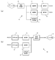
- the UL reception unit 10 includes an antenna unit 11, a wireless reception unit 12, demodulation units 13 and 15, decoding units 14 and 16, and a reference signal reception unit 17, as shown in FIG. 6A.
- the UL receiver 10 may have other functions or elements not shown in FIG.
- the wireless reception unit 12 receives the uplink signal transmitted from the terminal device 2 via the antenna unit 11.
- the uplink signal includes PUCCH (Physical Uplink Control Channel), PUSCH (Physical Uplink Shared Channel), and uplink reference signal (RS).
- the demodulation unit 13 and the decoding unit 14 reproduce the PUCCH signal from the uplink signal.
- the demodulation unit 15 and the decoding unit 16 reproduce the PUSCH signal from the uplink signal.
- the reference signal receiving unit 17 acquires the reference signal from the uplink signal.
- the schedule control unit 21 allocates resources to the scheduling request SR received from the terminal device 2.
- the schedule control unit 21 also generates a Grant signal.
- the grant signal includes information indicating the resources allocated to the scheduling request SR. It should be noted that the schedule control unit 21 can determine the resource for transmitting the URLLC signal and the resource for transmitting the non-URLLC signal.
- the PI control unit 22 When the schedule control unit 21 permits the transmission of the URLLC signal, the PI control unit 22 generates the preemption indicator PI.
- the preemption indicator PI requests the terminal device 2 for preemption processing. That is, the preemption indicator PI requests the terminal device 2 to stop the uplink transmission.
- the measurement section control unit 23 generates control information C1 representing the measurement section.
- the control information C1 includes information indicating the length of the measurement GAP and information indicating the cycle in which the measurement GAP is set.
- the measurement section control unit 23 notifies the terminal device 2 of the control information C1 by RRC (Radio Resource Control) signaling. Further, the control information C1 is transmitted to the terminal device 2 using, for example, a PDCCH (Physical Downlink Control Channel).
- RRC Radio Resource Control
- the low power section control unit 24 generates control information C2 indicating the low power section.
- the control information C2 includes information about the length of the low power section (for example, information indicating the length) and transmission power information indicating the transmission power of the terminal device 2 in the low power section. Note that the low power section control unit 24 notifies the terminal device 2 of the control information C2 by RRC signaling. Further, the control information C2 is transmitted to the terminal device 2 using, for example, the PDCCH.
- the control information 2C may be described as information regarding the transmission power.
- the DL transmission unit 30 includes coding units 31 and 33, modulation units 32 and 34, a reference signal generation unit 35, a wireless transmission unit 36, and an antenna unit 37.
- the DL transmitter 30 may include other functions or elements not shown in FIG. 6(b).
- the encoding unit 31 and the modulation unit 32 generate a PDCCH signal.
- the encoding unit 33 and the modulation unit 34 generate a PDSCH (Physical Downlink Shared Channel) signal.
- the reference signal generation unit 35 generates an uplink reference signal.
- the wireless transmission unit 36 transmits the PDCCH signal, the PDSCH signal, and the uplink reference signal via the antenna unit 37.
- FIG. 7 shows an example of arrangement of the measurement section and the low power section.
- the low power section is set immediately after the measurement section, as shown in FIG.
- a section that does not correspond to either the measurement section or the low power section is used as a normal section.
- the terminal device 2 transmits the uplink signal with lower power than in the normal section.
- the length of the low power section is determined by the low power section control unit 24.
- the low power section control unit 24 also determines the transmission power of the terminal device 2 in the low power section.
- the transmission power of the terminal device 2 in the low power section is determined relatively to the transmission power in the normal section, for example. That is, the transmission power of the terminal device 2 in the low power section is controlled to be lower than the transmission power in the normal section by the offset value P offset . In this case, the low power section control unit 24 determines the offset value P offset .
- the measurement section is, for example, Measurement GAP for measuring neighboring cells.
- the low power section is set immediately after each Measurement GAP, as shown in FIG.
- the measurement MAP length MGL and the cycle MGRP are notified from the base station 1 to the terminal device 2 as the control information C1.
- the measurement section may be an autonomous GAP, as shown in Fig. 7(c).
- the low power section is set immediately after Autonomous GAP.
- the terminal device 2 can autonomously determine the timing and length GL of the autonomous GAP.
- FIG. 8 shows an example of the terminal device 2.
- the terminal device 2 includes a DL reception unit 40, a PI detection unit 51, a transmission cancellation control unit 52, control information reception units 53 and 56, storage units 54 and 57, a measurement section control unit 55, a low power section control unit 58, and autonomous control.
- the unit 59 and the UL transmission unit 60 are provided.
- the terminal device 2 may have other functions or elements not shown in FIG.
- the DL reception unit 40 includes an antenna unit 41, a wireless reception unit 42, demodulation units 43 and 45, decoding units 44 and 46, and a reference signal reception unit 47.
- the DL reception unit 40 may include other functions or elements not shown in FIG.
- the radio receiving unit 42 receives the downlink signal transmitted from the base station 1 via the antenna unit 41.
- the downlink signal includes PDCCH, PDSCH, and downlink reference signal (RS).
- the demodulation unit 43 and the decoding unit 44 reproduce the PDCCH signal from the downlink signal.
- the demodulation unit 45 and the decoding unit 46 reproduce the PDSCH signal from the downlink signal.
- the reference signal receiving unit 47 acquires the reference signal from the downlink signal.
- the PI detection unit 51 detects the preemption indicator PI transmitted from the base station 1.
- the preemption indicator PI is transmitted using the PDCCH, as described above.
- the transmission cancellation control unit 52 generates a transmission stop signal and gives it to the UL transmission unit 60 when the PI detection unit 51 detects the preemption indicator PI.
- the transmission stop signal indicates to stop the uplink transmission. Therefore, when the terminal device 2 receives the preemption indicator PI, the terminal device 2 suspends the uplink transmission for a predetermined period.
- the control information receiving unit 53 receives the control information C1 transmitted from the base station 1.
- the control information C1 represents the length and cycle of the measurement GAP as described above. Further, the control information C1 is transmitted using the PDCCH. Then, the control information C1 is stored in the storage unit 54.
- the measurement section control unit 55 determines whether or not the terminal device 2 receives the downlink signal transmitted from the base station 1 in the measurement section. For example, when the received power of the downlink reference signal detected by the DL reception unit 40 is lower than a predetermined threshold value, the terminal device 2 executes the neighboring cell measurement using the measurement section. In this case, the measurement section control unit 55 determines that the terminal device 2 does not receive the downlink signal transmitted from the base station 1 in the measurement section.
- the measurement section may be a measurement GAP or an autonomous GAP.
- the measurement section control unit 55 refers to the control information C1 stored in the storage unit 54 and generates a transmission stop signal.
- the transmission stop signal indicates stop of uplink transmission. Then, the transmission stop signal is given to the UL transmission unit 60. Therefore, when the terminal device 2 does not receive the downlink signal in the measurement period, the terminal device 2 stops the uplink transmission in the measurement period.
- the measurement section control unit 55 when the terminal device 2 does not receive the downlink signal in the measurement section, the measurement section control unit 55 generates a reception stop signal and/or a frequency switching signal.
- the reception stop signal gives an instruction to stop downlink reception.
- the frequency switching signal instructs the DL receiving unit 40 to switch the downlink frequency to be received. Then, the reception stop signal and/or the frequency switching signal is given to the DL reception unit 40. Therefore, when the terminal device 2 does not receive the downlink signal in the measurement section, the terminal device 2 stops the downlink reception and/or switches the reception frequency for performing the peripheral cell measurement.
- the measurement section control unit 55 gives a start instruction to the low power section control unit 58.
- the start instruction is given from the measurement section control unit 55 to the low power section control unit 58 when the measurement section ends. That is, the low power section control unit 58 can detect the end timing of the measurement section by this start instruction.
- the control information receiving unit 56 receives the control information C2 transmitted from the base station 1.
- the control information C2 includes the length information indicating the length of the low power section and the transmission power information indicating the transmission power of the terminal device 2 in the low power section. Further, the control information C2 is transmitted using the PDCCH. Then, the control information C2 is stored in the storage unit 57.
- the low power section control unit 58 When the low power section control unit 58 receives the start instruction from the measurement section control unit 55, the low power section control unit 58 refers to the control information C2 stored in the storage unit 57 and generates a transmission power control signal.
- the transmission power control signal indicates the uplink transmission power. Specifically, the transmission power control signal represents the period during which the uplink transmission power is reduced and the amount of reduction in the uplink transmission power. Then, the transmission power control signal is provided to the UL transmission unit 60. Therefore, when the terminal device 2 does not receive the downlink signal in the measurement section, the terminal device 2 reduces the uplink transmission power according to the transmission power control signal. That is, the low power section is set.
- the autonomous control unit 59 generates control information D1 for setting Autonomous GAP.
- This control information D1 is given to the measurement section control unit 55.
- Autonomous GAP is treated as a measurement section by the measurement section control unit 55.
- the terminal device 2 does not have to include the autonomous control unit 59.
- the UL transmission unit 60 includes coding units 61 and 63, modulation units 62 and 64, a reference signal generation unit 65, a transmission power control unit 66, a wireless transmission unit 67, and an antenna unit 68. Equipped with.
- the UL transmitter 60 may include other functions or elements not shown in FIG. 9B.
- the encoding unit 61 and the modulation unit 62 generate a PUCCH signal.
- the encoder 63 and the modulator 64 generate a PUSCH signal.
- the reference signal generation unit 35 generates an uplink reference signal.
- the transmission power control unit 66 controls the uplink transmission power based on the transmission power control signal provided from the low power section control unit 58. For example, when the low power section is set by the low power section control unit 58, the transmission power control unit 66 reduces the uplink transmission power until the low power section ends.
- the wireless transmission unit 67 transmits the PUCCH signal, the PUSCH signal, and the uplink reference signal via the antenna unit 67. At this time, the wireless transmission unit 67 controls the uplink transmission power under the control of the transmission power control unit 66.
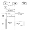
- FIG. 10 shows an example of a communication sequence according to the embodiment of the present invention.
- the terminal devices 2a and 2b are located in the cell of the base station 1.
- the terminal device 2a performs URLLC communication
- the terminal device 2b performs non-URLLC communication.
- the initial setting sequence is executed between the base station 1 and the terminal device 2b.
- the base station 1 transmits the control information C1 and C2 to the terminal device 2b.
- the control information C1 and C2 are notified from the base station 1 to the terminal device 2b by RRC signaling.
- the control information C1 and C2 are notified from the base station 1 to the terminal device 2 by an RRC reconfiguration sequence.
- control information C1 includes information indicating the length and cycle of the measurement section (that is, Measurement GAP).
- the control information C1 includes GAP information (MGL and MGRP shown in FIG. 7).
- GAP information is described in, for example, 3GPP TS38.331 V15.2.1 (2018-06)NR; Radio Resource Control (RRC) protocol specification.
- RRC Radio Resource Control
- the control information C2 includes length information indicating the length of the low power section and transmission power information for controlling the uplink transmission power.
- the length of the low power section is preferably equal to or longer than the length of the time resource allocated to the URLLC signal.
- the length of the low power section is preferably one slot or more.
- the slot length depends on the subcarrier spacing. For example, when the subcarrier intervals are 15 kHz, 30 kHz, 60 kHz, 120 kHz, and 240 kHz, the slot lengths are 1 ms, 0.5 ms, 0.25 ms, 0.125 ms, and 0.0626 ms, respectively.
- the information for controlling the uplink transmission power in the low power section is set as an offset value, for example. In this case, the offset value is selected from, for example, ⁇ 3 dB, ⁇ 4 dB,..., ⁇ 10 dB.
- control information C1 and C2 are described in the RRC reconfiguration message as shown in FIG. 11(b).
- C2_SectionLength represents the length of the low power section
- C2_ULTxPowerOffset represents the offset value of the uplink transmission power. Further, in the example shown in FIG. 11B, the control information C1 is omitted.
- control information C1 and C2 are transmitted from the base station 1 to the terminal device 2b using the PDCCH. Moreover, the control information C1 and C2 may be transmitted simultaneously or separately.
- the terminal device 2b stores the control information C1 and C2 received from the base station 1 in its own memory. Specifically, the control information C1 is stored in the storage unit 54, and the control information C2 is stored in the storage unit 57.
- the terminal device 2b When non-URLLC data is generated in the terminal device 2b, the terminal device 2b transmits the scheduling request SR to the base station 1.
- This scheduling request SR requests uplink resources for transmitting non-URLLC signals.
- the base station 1 determines the resource to be allocated to the terminal device 2b based on the scheduling request SR. Then, the base station 1 generates a permission signal and transmits it to the terminal device 2b.
- This permission signal includes information indicating the resource assigned to the terminal device 2b.
- the terminal device 2a transmits the scheduling request SR to the base station 1.
- This scheduling request SR requests an uplink resource for transmitting a URLLC signal.
- the base station 1 determines a resource to be assigned to the terminal device 2a based on the scheduling request SR. Then, the base station 1 generates a permission signal and transmits it to the terminal device 2a.
- the permission signal includes information indicating the resource assigned to the terminal device 2a.
- the base station 1 When the base station 1 receives the scheduling request SR for transmitting the uplink URLLC signal, the base station 1 transmits the permission signal to the terminal device 2a and the preemption indicator PI to the terminal device 2b.
- the preemption indicator PI requests the terminal device 2b for preemption processing (that is, cancellation of uplink transmission).
- the terminal device 2a and the terminal device 2b operate independently of each other. Therefore, the preemption indicator PI generated due to the scheduling request SR of the terminal device 2a is transmitted to the terminal device 2b regardless of the state of the terminal device 2b.
- the preemption indicator PI is transmitted from the base station 1 in the measurement section (that is, Measurement GAP) of the terminal device 2b.
- the terminal device 2b shall perform peripheral cell measurement in this measurement area. That is, it is assumed that the terminal device 2b does not receive the downlink signal transmitted from the base station 1 in this measurement section. In this case, the terminal device 2b does not receive the preemption indicator PI.
- the low power section is set as described with reference to FIG.
- the low power section is set immediately after the measurement section.
- the length of the low power section is determined by the base station 1 in this example. Further, in this example, the base station 1 also determines the offset value of the uplink transmission power in the low power section.
- the terminal device 2a transmits the URLLC signal by using the resource determined by the base station 1.
- the terminal device 2b transmits the non-URLLC signal. In this case, interference may occur between the URLLC signal transmitted from the terminal device 2a and the non-URLLC signal transmitted from the terminal device 2b.
- this non-URLLC signal is transmitted in the low power section. That is, the transmission power of this non-URLLC signal is reduced according to the control signal C2 generated by the base station 1. Therefore, the interference from the non-URLLC signal to the URLLC signal is suppressed. That is, the quality of the URLLC signal is improved as compared with the case shown in FIG.
- the terminal device 2b can transmit the non-URLLC signal in the low power section. Then, depending on the amount of power reduction in the low power section and/or the radio wave environment between the terminal device 2b and the base station 1, even if the non-URLLC signal is transmitted at low power, the base station 1 There is a possibility that the non-URLLC signal can be correctly received. In this case, the efficiency of non-URLLC communication is improved. That is, in the communication method according to the embodiment of the present invention, the efficiency of non-URLLC communication is improved while suppressing the interference from the non-URLLC signal to the URLLC signal.
- the uplink transmission power in the low power section is lowered, the interference from the non-URLLC signal to the URLLC signal is suppressed.
- the uplink transmission power in the low power section is too low, the base station 1 cannot receive the non-URLLC signal transmitted from the terminal device 2b. Therefore, it is preferable to determine the reduction amount of the uplink transmission power in the low power section in consideration of both the suppression of interference and the efficiency of non-URLLC communication.
- the terminal device 2b when the terminal device 2b performs the peripheral cell measurement, the terminal device 2b does not receive the downlink signal transmitted from the base station 1 in the measurement section. Therefore, the terminal device 2b cannot determine whether or not the preemption indicator PI is generated in the measurement section.
- the terminal device 2b transmits the non-URLLC signal even though the preemption indicator PI is generated in the measurement section, interference may occur between the non-URLLC signal and the URLLC signal.
- the terminal device 2b stops transmitting the non-URLLC signal even though the preemption indicator PI is not generated in the measurement section the communication efficiency of the terminal device 2b decreases. Therefore, also in this sense, setting the low power section immediately after the measurement section improves the efficiency of non-URLLC communication while suppressing the interference from the non-URLLC signal to the URLLC signal.
- FIG. 12 is a flowchart showing an example of processing for controlling the measurement section in the terminal device 2.
- the terminal device 2 constantly monitors the reception power of the downlink reference signal transmitted from the base station 1. Then, when the reception power of the downlink reference signal becomes lower than a predetermined threshold value, the DL reception unit 40 generates a start trigger for starting the peripheral cell measurement.
- the terminal device 2 receives the control information C1 and C2 from the base station 1.
- the control information C1 includes information indicating the length and cycle of the measurement section (that is, Measurement GAP).
- the control information C2 also includes information indicating the length of the low power section and the uplink transmission power. Then, the control information C1 and C2 are stored in the storage units 54 and 57, respectively.
- the terminal device 2 autonomously executes the peripheral cell measurement, the terminal device 2 generates the control information D1 including the information indicating the length of the measurement section (that is, Autonomous GAP).
- the measurement section control unit 55 monitors a start trigger for instructing the start of peripheral cell measurement.
- the start trigger is generated by the DL reception unit 40 as described above. Further, when the start trigger is not generated, the terminal device 2 executes a normal communication operation.
- the measurement section control unit 55 monitors the start timing of GAP in S2.
- GAP is Measurement GAP or Autonomous GAP.
- the measurement section control unit 55 controls communication in the measurement section. For example, the measurement section control unit 55 generates a transmission stop signal instructing to stop the uplink transmission and gives it to the UL transmission unit 60.
- the measurement section control unit 55 generates a reception stop signal instructing to stop downlink reception and gives it to the DL reception unit 40.
- the measurement section control unit 55 generates a frequency switching signal for receiving the reference signal of the peripheral cell and gives it to the DL receiving unit 40. By this control, peripheral cell measurement is realized.
- the measurement section control unit 55 issues a start notification and gives it to the low power section control unit 58.
- This start notification instructs the start of the low power section. Therefore, when the measurement section control unit 55 issues a start notification, the low power section control unit 58 starts communication control in the low power section.
- the measurement section control unit 55 monitors an end trigger that gives an instruction to end the peripheral cell measurement.
- the termination trigger is generated by the DL reception unit 40, for example, when the reception power of the downlink reference signal becomes higher than a predetermined threshold. Alternatively, the termination trigger is generated when the terminal device 2 executes the handover. Then, when the end trigger is generated, the process of the measurement section control unit 55 ends.
- the terminal device 2 executes the peripheral cell measurement, the terminal device 2 does not receive the downlink signal transmitted from the base station 1 in the measurement section. Then, the terminal device 2 cannot determine whether or not the preemption indicator PI is generated in the measurement section. Therefore, the terminal device 2 issues a start notification and gives it to the low power section control unit 58 in order to set the low power section immediately after this measurement section.
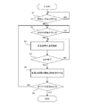
- FIG. 13 is a flowchart showing an example of processing for controlling the low power section in the terminal device 2. As described with reference to FIG. 12, when the measurement section ends, the measurement section control unit 55 gives a start instruction to the low power section control unit 58.
- the low power section control unit 58 monitors the start notification. Then, when the start notification is received, the low power section control unit 58 activates a counter in S12. That is, when the measurement section ends, the counter is activated. It should be noted that this counter counts the elapsed time from the start time point of the low power section.
- the low power section control unit 58 controls communication in the low power section. Specifically, the low power section control unit 58 reduces the transmission power of the uplink signal according to the control information C2 notified from the base station 1.
- the transmission power PP PUSCH [dBm] of PUSCH in the low power section is expressed by equation (1).
- P PUSCH represents the transmission power of PUSCH in the normal period.
- min represents an operator that selects the smaller value from the values in parentheses.
- P offset represents the offset value represented by the control information C2.
- the transmission power PP PUCCH [dBm] of PUCCH in the low power section is expressed by equation (2).
- P PUCCH represents the transmission power of PUCCH in the normal period.
- the transmission power PP SRS [dBm] of the uplink reference signal SRS in the low power section is expressed by Expression (3).
- P SRS represents the transmission power of the uplink reference signal SRS in the normal section.
- the process of reducing the transmission power is continued until the count value reaches the value indicating the length of the low power section (C2_SectionLength in the example shown in FIG. 11B). Then, when the count value reaches this value, the process of the low power section control unit 58 ends. After that, the terminal device 2 transmits the uplink signal with normal power.
- the low power section is set immediately after the measurement section. Then, in the low power section, the terminal device 2 transmits the uplink signal with lower power than in the normal section.
- the measurement section is an example of "a section in which the terminal device is not required to receive the downlink signal". Therefore, the terminal device 2 may set the low power section immediately after the predetermined section other than the measurement section. For example, when measuring the SFTD (SFN and Frame Timing Difference) by switching the secondary radio frequency for an asynchronous NR peripheral cell, in order to suppress the influence of the radio frequency switching, a section in which communication with the connected cell is prohibited Is set. In this case, the low power period may be set immediately after this section.
- SFTD SFN and Frame Timing Difference
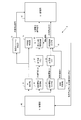
- FIG. 14 shows an example of a terminal device according to another embodiment of the present invention.
- the terminal device 2 according to another embodiment includes a PI detection/monitoring unit 71 in addition to the configuration shown in FIG.
- the DL reception unit 40, the PI detection unit 51, the transmission cancellation control unit 52, the control information reception units 53 and 56, the storage units 54 and 57, the measurement section control unit 55, the autonomous control unit 59, and the UL transmission unit 60 are shown in FIG. It is substantially the same in FIG. However, the low power section control unit 58 operates in cooperation with the PI detection/monitoring unit 71 as necessary.
- the PI detection/monitoring unit 71 monitors whether or not the terminal device 2 receives the preemption indicator PI from the base station 1 in the low power section.
- the preemption indicator PI is detected by the PI detection unit 51. Then, when the PI detection unit 51 detects the preemption indicator PI in the low power period, the PI detection monitoring unit 71 generates an early end notification and gives it to the low power period control unit 58.
- the low power section control unit 58 sets the low power section immediately after the measurement section, similarly to the configuration shown in FIG. Here, the length of the low power section is determined by the base station 1. However, when the low power section control unit 58 receives the early end notification from the PI detection monitoring section 71, the low power section control unit 58 ends the low power section.
- FIG. 15 shows an example of a communication sequence according to another embodiment.
- the terminal devices 2a and 2b are located in the cell of the base station 1.
- the terminal device 2a performs URLLC communication
- the terminal device 2b performs non-URLLC communication.
- the low power section is set immediately after the measurement section.
- the length LPL of the low power section is determined by the base station 1 and is notified to the terminal device 2b as control information C2.
- the terminal device 2a transmits the scheduling request SR for the URLLC signal to the base station 1 in the low power section of the terminal device 2b. Then, the base station 1 transmits the permission signal to the terminal device 2a and the preemption indicator PI to the terminal device 2b. In this case, the terminal device 2b receives the preemption indicator PI from the base station 1 in the low power section. Note that, unlike the measurement period, the terminal device 2b receives the downlink signal transmitted from the base station 1 in the low power period.
- the PI detection monitoring section 71 gives an early end notification to the low power section control section 58. Then, the low power section control unit 58 forcibly ends the low power section in response to the early end notification. Further, the transmission cancellation control unit 52 sets the transmission suspension section according to the received preemption indicator PI. In the transmission suspension period, the terminal device 2b does not transmit the uplink signal.
- the transmission suspension section is set, for example, immediately after the low power section control unit 58 forcibly ends the low power section. Further, it is preferable that the length of the transmission suspension section is equal to or longer than the length of the time resource assigned to the URLLC signal corresponding to the preemption indicator PI received by the terminal device 2b.
- the terminal device 2b when the terminal device 2b receives the preemption indicator PI in the low power section, the terminal device 2b does not transmit the uplink signal. That is, when the terminal device 2a transmits the URLLC signal, the terminal device 2b does not transmit the uplink signal. Therefore, the quality of the URLLC signal is maintained.
- FIG. 16 is a flowchart showing an example of processing for controlling a low power section in a terminal device according to another embodiment. Note that the processing of S11 to S13 is substantially the same in FIG. 13 and FIG. 16, that is, when the measurement section ends, the low power section control unit 58 sets the low power section.
- the low power section control unit 58 waits for an early end notification.
- the early termination notification is issued by the PI detection monitoring unit 71 when the terminal device 2b receives the preemption indicator PI in the low power section.
- the process of the low power section control unit 58 proceeds to S14. That is, when the terminal device 2b does not receive the preemption indicator PI, the processing in the low power section is continued. On the other hand, when the early termination notification is issued, the process of the low power section control unit 58 is immediately terminated. That is, when the terminal device 2b receives the preemption indicator PI in the low power period, the low power period ends.
- the transmission cancellation control unit 52 sets the transmission stop period according to the preemption indicator PI. In this case, the terminal device 2b does not transmit the uplink signal until the transmission suspension period ends.
- FIG. 17 shows an example of the hardware configuration of the base station 1 and the terminal device 2.
- the base station 1 includes a wireless reception unit 81, a wireless transmission unit 82, a processor 83, and a memory 84.
- the wireless receiver 81 and the wireless transmitter 82 correspond to the UL receiver 10 and the DL transmitter 30 shown in FIG. 5, respectively.
- the processor 83 provides the function of the base station 1 by executing the communication program stored in the memory 84. Specifically, the processor 83 executes the communication program describing the processes of the schedule control unit 21, the PI control unit 22, the measurement section control unit 23, and the low power section control unit 24, and the function of the base station 1 is provided. ..
- the terminal device 2 includes a wireless reception unit 91, a wireless transmission unit 92, a processor 93, and a memory 94.
- the wireless receiver 91 and the wireless transmitter 92 correspond to the DL receiver 40 and the UL transmitter 60 shown in FIG. 8, respectively.
- the processor 93 provides the function of the terminal device 2 by executing the communication program stored in the memory 94.
- the communication program describing the processing of the PI detection unit 51, the transmission cancellation control unit 52, the control information reception units 53 and 56, the measurement section control unit 55, the low power section control unit 58, and the autonomous control unit 59 is a processor. It is performed by 93 and the function of the terminal device 2 is provided.
- the PI detection unit 51 the transmission cancellation control unit 52, the control information reception units 53 and 56, the measurement section control unit 55, the low power section control unit 58, the autonomous control unit.
- the communication program describing the processing of the PI detection and monitoring unit 71 is executed by the processor 93, and the function of the terminal device 2 is provided.
Landscapes
- Engineering & Computer Science (AREA)
- Computer Networks & Wireless Communication (AREA)
- Signal Processing (AREA)
- Mobile Radio Communication Systems (AREA)
Abstract
Un appareil terminal comprend une unité de transmission, une unité de réception, une unité d'acquisition d'information de commande, et une unité de commande. L'unité de réception reçoit un signal de liaison descendante transmis à partir de la station de base. L'unité de transmission transmet un signal de liaison montante à la station de base. L'unité d'acquisition d'informations de commande acquiert, à partir de la station de base, des informations de commande relatives à une seconde section qui est établie immédiatement après une première section durant laquelle la réception du signal de liaison descendante n'est pas demandée. Lorsque l'unité de réception ne reçoit pas de signal de liaison descendante pendant la première section, l'unité de commande commande la transmission du signal de liaison montante par l'unité de transmission pendant la seconde section conformément aux informations de commande.
Priority Applications (1)
| Application Number | Priority Date | Filing Date | Title |
|---|---|---|---|
| PCT/JP2019/005370 WO2020166010A1 (fr) | 2019-02-14 | 2019-02-14 | Appareil terminal, appareil de station de base et système de communication sans fil |
Applications Claiming Priority (1)
| Application Number | Priority Date | Filing Date | Title |
|---|---|---|---|
| PCT/JP2019/005370 WO2020166010A1 (fr) | 2019-02-14 | 2019-02-14 | Appareil terminal, appareil de station de base et système de communication sans fil |
Publications (1)
| Publication Number | Publication Date |
|---|---|
| WO2020166010A1 true WO2020166010A1 (fr) | 2020-08-20 |
Family
ID=72043898
Family Applications (1)
| Application Number | Title | Priority Date | Filing Date |
|---|---|---|---|
| PCT/JP2019/005370 Ceased WO2020166010A1 (fr) | 2019-02-14 | 2019-02-14 | Appareil terminal, appareil de station de base et système de communication sans fil |
Country Status (1)
| Country | Link |
|---|---|
| WO (1) | WO2020166010A1 (fr) |
Citations (2)
| Publication number | Priority date | Publication date | Assignee | Title |
|---|---|---|---|---|
| EP3340697A1 (fr) * | 2016-12-23 | 2018-06-27 | ASUSTek Computer Inc. | Procédé et appareil de multiplexage de transmissions pour différents services dans un système de communication sans fil |
| JP2018191104A (ja) * | 2017-05-01 | 2018-11-29 | ソニー株式会社 | 通信装置、基地局装置、方法及び記録媒体 |
-
2019
- 2019-02-14 WO PCT/JP2019/005370 patent/WO2020166010A1/fr not_active Ceased
Patent Citations (2)
| Publication number | Priority date | Publication date | Assignee | Title |
|---|---|---|---|---|
| EP3340697A1 (fr) * | 2016-12-23 | 2018-06-27 | ASUSTek Computer Inc. | Procédé et appareil de multiplexage de transmissions pour différents services dans un système de communication sans fil |
| JP2018191104A (ja) * | 2017-05-01 | 2018-11-29 | ソニー株式会社 | 通信装置、基地局装置、方法及び記録媒体 |
Non-Patent Citations (1)
| Title |
|---|
| FUJITSU: "Discussion on uplink preemption indication", 3GPP TSG RAN WG1 #95 R1-1812415, 26 November 2018 (2018-11-26), XP051478615 * |
Similar Documents
| Publication | Publication Date | Title |
|---|---|---|
| US11178721B2 (en) | Mobile communication system, user terminal, and base station | |
| EP2712113B1 (fr) | Procédé et appareil permettant d'utiliser une pluralité de cellules dans un système de communication | |
| RU2713410C1 (ru) | Способ функционирования сотовой сети, включающий в себя высокочастотную пакетную передачу | |
| JP7593950B2 (ja) | ビーム管理方法及び装置、ユーザ機器 | |
| KR102123434B1 (ko) | 셀룰러 이동 통신 시스템에서 스케쥴링 요청 방법 및 장치 | |
| US9860007B2 (en) | User terminal, radio base station, and radio communication method | |
| EP2802180A1 (fr) | Procédé de commande de communication D2D et dispositif de contrôleur correspondant et dispositif mobile | |
| CN111869152A (zh) | 波束指示方法、装置和系统 | |
| CN108668374B (zh) | 一种调度请求的传输方法及装置 | |
| EP3881627B1 (fr) | Communications avec des ressources de liaison montante préconfigurées | |
| US20210337511A1 (en) | Facilitating bandwidth part selection in wireless communication systems | |
| KR20140121319A (ko) | 무선 통신 시스템에서 채널 정보 전송 방법 및 장치 | |
| US20200396728A1 (en) | Communication Method And Communications Apparatus | |
| WO2015015766A1 (fr) | Dispositif de communication, son procédé de commande, dispositif de station de base, son procédé de commande et programme | |
| JP7347664B2 (ja) | 無線通信方法、装置及びシステム | |
| EP4710487A1 (fr) | Procédés, dispositifs de communication semi-duplex et équipement d'infrastructure | |
| CN107493603A (zh) | 调整帧结构的方法、网络设备与终端 | |
| US20240365376A1 (en) | Network nodes, systems, methods, circuitry and computer program products | |
| CN113661670B (zh) | Ue、无线电网络节点和其中执行的方法 | |
| WO2020166010A1 (fr) | Appareil terminal, appareil de station de base et système de communication sans fil | |
| US20240205905A1 (en) | Communication method and device | |
| KR102911086B1 (ko) | 무선통신시스템에서 SCell(secondary cell) 빔실패보고를 위한 스케쥴링 요청과 다른 상향링크 전송 간에 우선순위를 결정하는 방법 및 장치 | |
| JP2023110023A (ja) | 通信のための方法、端末デバイス、及びコンピュータ読み取り可能な媒体 | |
| WO2023156708A1 (fr) | Affinement de faisceau de réception d'équipement utilisateur basé sur la mesure d'un second équipement utilisateur |
Legal Events
| Date | Code | Title | Description |
|---|---|---|---|
| 121 | Ep: the epo has been informed by wipo that ep was designated in this application |
Ref document number: 19915138 Country of ref document: EP Kind code of ref document: A1 |
|
| NENP | Non-entry into the national phase |
Ref country code: DE |
|
| 122 | Ep: pct application non-entry in european phase |
Ref document number: 19915138 Country of ref document: EP Kind code of ref document: A1 |
|
| NENP | Non-entry into the national phase |
Ref country code: JP |