WO2020166211A1 - Robot mobile, procédé de commande d'un robot mobile, et programme - Google Patents
Robot mobile, procédé de commande d'un robot mobile, et programme Download PDFInfo
- Publication number
- WO2020166211A1 WO2020166211A1 PCT/JP2019/050492 JP2019050492W WO2020166211A1 WO 2020166211 A1 WO2020166211 A1 WO 2020166211A1 JP 2019050492 W JP2019050492 W JP 2019050492W WO 2020166211 A1 WO2020166211 A1 WO 2020166211A1
- Authority
- WO
- WIPO (PCT)
- Prior art keywords
- drive
- leg
- traveling
- switching
- wheel
- Prior art date
- Legal status (The legal status is an assumption and is not a legal conclusion. Google has not performed a legal analysis and makes no representation as to the accuracy of the status listed.)
- Ceased
Links
Images





Classifications
-
- B—PERFORMING OPERATIONS; TRANSPORTING
- B62—LAND VEHICLES FOR TRAVELLING OTHERWISE THAN ON RAILS
- B62D—MOTOR VEHICLES; TRAILERS
- B62D57/00—Vehicles characterised by having other propulsion or other ground- engaging means than wheels or endless track, alone or in addition to wheels or endless track
- B62D57/02—Vehicles characterised by having other propulsion or other ground- engaging means than wheels or endless track, alone or in addition to wheels or endless track with ground-engaging propulsion means, e.g. walking members
- B62D57/032—Vehicles characterised by having other propulsion or other ground- engaging means than wheels or endless track, alone or in addition to wheels or endless track with ground-engaging propulsion means, e.g. walking members with alternately or sequentially lifted supporting base and legs; with alternately or sequentially lifted feet or skid
-
- B—PERFORMING OPERATIONS; TRANSPORTING
- B25—HAND TOOLS; PORTABLE POWER-DRIVEN TOOLS; MANIPULATORS
- B25J—MANIPULATORS; CHAMBERS PROVIDED WITH MANIPULATION DEVICES
- B25J5/00—Manipulators mounted on wheels or on carriages
-
- B—PERFORMING OPERATIONS; TRANSPORTING
- B60—VEHICLES IN GENERAL
- B60K—ARRANGEMENT OR MOUNTING OF PROPULSION UNITS OR OF TRANSMISSIONS IN VEHICLES; ARRANGEMENT OR MOUNTING OF PLURAL DIVERSE PRIME-MOVERS IN VEHICLES; AUXILIARY DRIVES FOR VEHICLES; INSTRUMENTATION OR DASHBOARDS FOR VEHICLES; ARRANGEMENTS IN CONNECTION WITH COOLING, AIR INTAKE, GAS EXHAUST OR FUEL SUPPLY OF PROPULSION UNITS IN VEHICLES
- B60K31/00—Vehicle fittings, acting on a single sub-unit only, for automatically controlling vehicle speed, i.e. preventing speed from exceeding an arbitrarily established velocity or maintaining speed at a particular velocity, as selected by the vehicle operator
-
- B—PERFORMING OPERATIONS; TRANSPORTING
- B62—LAND VEHICLES FOR TRAVELLING OTHERWISE THAN ON RAILS
- B62D—MOTOR VEHICLES; TRAILERS
- B62D57/00—Vehicles characterised by having other propulsion or other ground- engaging means than wheels or endless track, alone or in addition to wheels or endless track
- B62D57/02—Vehicles characterised by having other propulsion or other ground- engaging means than wheels or endless track, alone or in addition to wheels or endless track with ground-engaging propulsion means, e.g. walking members
- B62D57/028—Vehicles characterised by having other propulsion or other ground- engaging means than wheels or endless track, alone or in addition to wheels or endless track with ground-engaging propulsion means, e.g. walking members having wheels and mechanical legs
-
- G—PHYSICS
- G05—CONTROLLING; REGULATING
- G05D—SYSTEMS FOR CONTROLLING OR REGULATING NON-ELECTRIC VARIABLES
- G05D1/00—Control of position, course, altitude or attitude of land, water, air or space vehicles, e.g. using automatic pilots
- G05D1/02—Control of position or course in two dimensions
- G05D1/021—Control of position or course in two dimensions specially adapted to land vehicles
Definitions
- the present disclosure relates to a traveling robot, a traveling robot control method, and a program.
- the invention relates to a walking robot that moves by moving the legs back and forth and a running robot that switches and moves between wheels that rotate and move wheels, a running robot control method, and a program.
- traveling robots that move by moving between walking legs by moving the legs back and forth and by running wheels by rotating the wheels.
- it is necessary to store and fix the legs above the ground contact surface of the wheels when the wheels are traveling.
- it is necessary to control the ground contact surface of the legs to be located below the wheels.
- the leg and wheel driving sources are not provided, that is, a plurality of actuators such as motors are not provided, and the leg and wheel driving are performed by one driving source. It is preferable to adopt a configuration for executing the driving of.
- an actuator sharing configuration there is a problem that a time lag occurs at the time of switching between the leg and the wheel, and the moving speed decreases during this switching period.
- Patent Document 1 Japanese Unexamined Patent Publication No. 2009-113135 is an example of conventional technology that discloses a traveling robot that moves by switching between leg traveling and wheel traveling.
- This document discloses a bipedal walking robot having a three-point grounded tip by wheels and a support at the tip of the leg.
- This configuration has an advantage that the legs and the wheels can be switched in a short time.
- an actuator for driving wheels is required, which increases weight cost.
- the weight of the legs must be supported by using the leg actuators, so that the energy efficiency of the movement is poor.
- Patent Document 2 Japanese Patent Laid-Open No. 2008-260117 discloses a robot that has wheels at a hip joint and controls electric power supply by using a common power source for a hip joint actuator and an actuator for driving wheels to switch between legs and wheels. Is disclosed. The leg is moved to a predetermined position while the wheels are moving. In this configuration, although the leg and the wheel have the same power source, it is necessary to drive the actuator for compensating the weight of the leg when the wheel is traveling, which results in a large energy consumption. In addition, an extra drive wheel actuator is required.
- Patent Document 3 Japanese Patent Laid-Open No. 2008-0623066
- Japanese Patent Laid-Open No. 2008-062306 Japanese Patent Laid-Open No. 2008-062306
- the leg and the wheel can be seamlessly moved, but the leg length must be equal to or less than the radius of the circular frame of the wheel, and the leg length cannot be freely designed.
- Patent Document 4 Japanese Patent Laid-Open No. 2008-049429 discloses a robot that drives legs and wheels with the same number of motors. It is a robot that drives the motors synchronously to move the wheels and differentially drives the legs to swing to move the legs. In this configuration, the motor is efficiently used for both the wheel movement and the leg movement, but the wheel is required for the number of joints of the leg, and there is a drawback that the weight increases. In addition, the movement modes of the legs and wheels cannot be changed seamlessly.
- the present disclosure has been made in view of the above problems, for example, in a robot that performs continuous traveling by switching between leg traveling and wheel traveling, it is possible to suppress a decrease in moving speed when switching between leg and wheel. It is an object to provide a traveling robot, a traveling robot control method, and a program.
- the first aspect of the present disclosure is Drive unit, A clutch that switches the transmission destination of the driving force of the drive unit, A leg driven by the driving force of the drive unit, Wheels driven by the driving force of the drive unit, Has a controller,
- the control unit is There is a traveling robot that executes traveling speed control before drive switching so that the traveling speed after drive switching is substantially equal to the traveling speed before drive switching at the time of drive switching between leg drive and wheel drive.
- the second aspect of the present disclosure is A traveling robot control method executed in a traveling robot,
- the traveling robot is A drive unit and a clutch that switches the transmission destination of the drive force of the drive unit, Legs and wheels driven by the driving force of the driving unit, Has a controller,
- the control unit In the traveling robot control method, the traveling speed control is executed before the drive switching so that the traveling speed after the drive switching is substantially equal to the traveling speed before the drive switching when the drive is switched between the leg drive and the wheel drive.
- the third aspect of the present disclosure is It is a program to execute the traveling robot control in the traveling robot,
- the traveling robot is A drive unit and a clutch that switches the transmission destination of the drive force of the drive unit, Legs and wheels driven by the driving force of the driving unit, Has a controller,
- the program in the control unit, In the program, when the drive is switched between the leg drive and the wheel drive, the traveling speed control is executed before the drive switching so that the traveling speed after the drive switching becomes substantially equal to the traveling speed before the drive switching.
- the program of the present disclosure is, for example, a program that can be provided by a storage medium or a communication medium provided in a computer-readable format to an information processing device or a computer system that can execute various program codes.
- a program that can be provided by a storage medium or a communication medium provided in a computer-readable format to an information processing device or a computer system that can execute various program codes.
- system in this specification is a logical set configuration of a plurality of devices, and is not limited to one in which the devices of the respective configurations are in the same housing.
- FIG. 1 is a diagram showing a traveling robot 100 of the present disclosure.
- the traveling robot 100 according to the present disclosure is a traveling robot that switches and moves between walking-type leg traveling in which the legs are moved back and forth and wheel traveling in which the wheels are rotated.
- the traveling robot shown in FIG. 1 has a configuration in which an actuator such as a motor that is a drive unit is shared. In this way, by adopting a configuration in which one driving unit is shared, it is possible to reduce the overall weight.
- the traveling robot 100 can perform (a) leg traveling and (b) wheel traveling.
- the traveling robot 100 is traveling in the arrow direction (from left to right).
- the traveling robot 100 switches between (a) leg traveling and (b) wheel traveling during traveling. be able to.
- switching between (a) leg traveling and (b) wheel traveling is realized without causing a speed decrease or a large speed change.
- the traveling robot 100 has legs 101, wheels 102, a clutch 103, and a lock mechanism 104.
- the leg 101 is used when performing walking type leg running.
- the joint is rotated by the driving force of an actuator such as a motor. That is, the driving force of an actuator such as a motor is converted into rotational driving of the joints r1, r2, r3, and r4 shown in the figure, and the leg 101 is moved back and forth to perform walking type leg running.
- the wheels 102 are used when traveling on wheels.
- the wheels 102 are rotationally driven by the driving force of an actuator such as a motor. That is, the driving force of an actuator such as a motor is converted into rotational driving of the axle parts of r5 and r6 shown in the figure, and the wheels 102 are rotated to drive the wheels.
- the clutch 103 has a drive force transmission switching mechanism that switches between a leg drive setting for transmitting the drive force of an actuator such as a motor to the leg 101 and a wheel drive setting for transmitting to the wheels 102.
- a leg drive setting for transmitting the drive force of an actuator such as a motor
- a wheel drive setting for transmitting to the wheels 102.
- it has a dog clutch that switches the transmission destination of power of an actuator such as a motor.
- the power of the actuator When walking using the leg 101, the power of the actuator is transmitted to the joint part of the leg 101 via the clutch 103 to drive the leg. During this leg driving period, the driving force is not transmitted to the wheels 102. Further, when the wheels 102 are running, the power of the actuator is transmitted to the wheels via the clutch 103. No driving force is transmitted to the legs during this period.
- the mechanism for switching the power transmission of the actuator is not limited to the dog clutch, but may be an electromagnetic clutch or the like.
- the lock mechanism 104 is a mechanism for fixing the leg 101 during traveling of the wheels shown in FIG. 1(b).
- the lock mechanism 104 for example, a mechanism for fixing the leg 101 to the robot body by inserting a pin provided in the lock mechanism 104 into a hole or a recess provided in the leg 101 can be used.
- This locking process of the leg 101 by the lock mechanism 104 prevents the leg 101 from coming into contact with the wheel 102 or the ground, that is, when the wheel is traveling as shown in FIG. 1B, that is, when power is not transmitted to the leg 101. Can be prevented. Note that the driving force from the same driving source as the driving sources of the legs 101 and the wheels 102 can be used for the locking process and the unlocking process of the lock mechanism 104.
- the lock mechanism 104 uses one lock mechanism 104 shared by the front and rear legs 101, but the lock mechanism 104 may be individually configured for each leg.
- the lock mechanism 104 may have a configuration in which all of these four legs are fixed by one lock mechanism. Further, a lock mechanism having the same structure as the clutch mechanism 103 described above may be used.
- the traveling robot 100 shown in FIG. 1 has sensors and encoders for measuring the rotation angles of the legs 101 and the wheels 102, and a speedometer. It also has a sensor that detects the traveling environment. The sensor determines the environment of the traveling surface such as whether the ground is smooth or uneven. For example, wheels are run on level ground and legs are run on level ground.
- the senor detects whether the running surface is flat, uphill, downhill, the angle of the slope, and whether the stairs are uphill or downhill, and the size of the step. To do.
- the sensor is composed of, for example, a camera, a distance sensor, or the like.
- the control unit of the traveling robot executes traveling control based on the detection information from these sensors and speedometers. Specifically, switching control between leg traveling using the legs 101 and wheel traveling using the wheels 102 is performed. Further, leg traveling using the legs 101, wheel traveling using the wheels 102, and traveling speed control during each traveling are performed.
- the control unit of the traveling robot 100 performs, for example, wheel traveling on level ground and leg traveling on uneven ground.
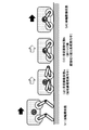
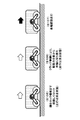
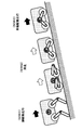
- FIG. 2 shows an example of transition from the leg drive state to the wheel drive state.
- the state of the traveling robot when transitioning from the leg drive state to the wheel drive state changes as follows with the passage of time.
- T1 Leg drive state
- t2 Glide movement state a (leg storage processing is being executed)
- T3 Glide movement state b (during drive switching processing after leg lock)
- the leg drive state is a state in which driving force from an actuator such as a motor is transmitted to the leg 101, and traveling by leg drive is executed.
- the sliding movement state “a” is an execution period of the storage processing of the legs 101.
- the driving force from the actuator such as the motor is transmitted to the leg 101, and this driving force is used for storing the leg 101, that is, for moving the leg 101 to the lock position of the lock mechanism 104. It Therefore, during this period, the driving force from the actuator such as the motor cannot be used for the moving process of the traveling robot 100.
- the wheel 102 to which the driving force is not transmitted, runs by idling.
- Wheel driving state is a state after the driving force from the actuator such as a motor is switched to the wheels 102.
- the driving force from an actuator such as a motor is transmitted to the wheels 102, and the wheels 102 are rotationally driven.
- the traveling robot 100 moves by driving and rotating wheels 102.
- This period is a period in which the clutch 103 switches the transmission destination of the driving force of the actuator such as a motor from the leg 101 to the wheel 102.
- the driving force of an actuator such as a motor is not used for the movement of the traveling robot 100, and the movement is performed by the wheel 102 gliding by idling.
- the lock mechanism is ON, and the leg is fixed at the position of the lock mechanism 104.
- Driving force transmission state (leg) OFF
- Driving force transmission state (wheel) ON
- Lock mechanism state ON This is the state. That is, the driving force of an actuator such as a motor is not transmitted to the legs 101 but to the wheels 102.
- the driving force of the actuator such as the motor is transmitted to the wheels 102, and the traveling robot 100 moves by the rotation of the wheels 102.
- the lock mechanism is ON, and the leg is fixed at the position of the lock mechanism 104.
- the process of storing and locking the leg 104 and the process of switching the drive force transmission destination from the actuator such as the motor by the clutch control are performed. Will be required.
- the driving force from the actuator such as the motor cannot be used for moving (running) the traveling robot 100. That is, a driving force unusable traveling period occurs in which the driving force cannot be applied to the movement process. As a result, the speed of the traveling robot 100 is reduced during the traveling period when the driving force cannot be used.
- this driving force unusable traveling period occurs both during the switching process from the leg drive to the wheel drive and during the switching process from the wheel drive to the leg drive.
- the traveling robot 100 executes control that suppresses a decrease in speed during the traveling period where the driving force cannot be used.
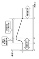
- the graph shown in FIG. 4 is a graph in which the horizontal axis represents time (t) and the vertical axis represents speed (v), and shows the change in speed when switching from leg drive traveling to wheel drive traveling.
- the time t0 to t1 and the time t1 to t2 are leg drive traveling periods.
- Times t2 to t3 are periods required for leg storage and switching of driving force by clutch operation (switching from legs to wheels). This period is the traveling period in which the driving force cannot be used.
- the period from time t3 is the wheel drive traveling period.
- the control unit of the traveling robot 100 sets the leg drive acceleration travel period immediately before the leg drive travel is completed, that is, immediately before the leg drive travel period is transitioned to the drive force unavailable travel period. It is a period of time t1 to t2 shown in the figure.
- the control unit of the traveling robot 100 according to the present disclosure performs the drive control of the legs 101 and executes the acceleration processing for increasing the traveling speed of the traveling robot 100 immediately before entering the traveling period in which the driving force cannot be used. Specifically, for example, a kicking motion by the leg 101 is executed to accelerate the traveling robot 100.
- the driving force cannot be used in the traveling period from time t2, that is, the driving force switching (switching from the leg to the wheel) processing by the leg storage and the clutch operation is performed, and the moving speed gradually decreases. ..
- the switching of the driving force by the leg storage and the clutch operation switching from the leg to the wheel
- the driving force of the actuator such as the motor
- the traveling speed of the traveling robot 100 at the wheel drive traveling start time t3 is substantially equal to the speed V0 during the time t0 to t1 during which the leg drive traveling is executed. That is, the wheel drive traveling can be started without causing a large reduction in speed.
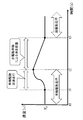
- FIG. 5 shows a change in speed when switching from wheel drive traveling to leg drive traveling.
- the time t0 to t1 and the time t1 to t2 are the wheel drive traveling period.
- Time t2 to t3 is a period required for unlocking the legs and switching the driving force by switching the clutch (switching the wheels to the legs). This period is the traveling period in which the driving force cannot be used.
- the period from time t3 is the leg drive traveling period.
- the control unit of the traveling robot 100 of the present disclosure sets the wheel drive acceleration travel period immediately before the wheel drive travel is completed, that is, immediately before the wheel drive travel period is transitioned to the drive power unavailable travel period. It is a period of time t1 to t2 shown in the figure.
- the control unit of the traveling robot 100 according to the present disclosure performs drive control of the wheels 102 and executes an acceleration process for increasing the traveling speed of the traveling robot 100 immediately before entering the traveling period in which the driving force cannot be used. Specifically, the traveling speed of the wheels 102 is increased to accelerate the traveling robot 100.
- the driving force cannot be used from the time t2, that is, the period for executing the process of switching the driving force by switching the lock of the leg and operating the clutch (switching from the wheel to the leg) is performed, and the moving speed gradually decreases. To do.
- the switching of the driving force by the leg lock release and the clutch operation (switching from the wheel to the leg) is completed, the driving force of the actuator such as the motor is transmitted to the leg 101, and the traveling by the leg driving is started.
- the traveling speed of the traveling robot 100 at the leg drive traveling start time t3 is substantially equal to the speed V0 during the time t0 to t1 during which the wheel drive traveling is executed. That is, the leg drive traveling can be started without causing a large speed reduction.
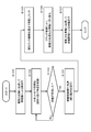
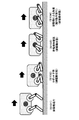
- a switching sequence from leg drive to wheel drive executed by the traveling robot 100 of the present disclosure will be described with reference to the flowchart shown in FIG. 6.
- the processing according to the flowchart shown in FIG. 6 can be executed by the control unit (data processing unit) of the traveling robot 100 according to a program stored in the storage unit of the traveling robot 100, for example.
- it can be performed as a program execution process by a processor such as a CPU having a program execution function.
- the processing of each step of the flow shown in FIG. 6 will be described below.
- Step S101 First, in step S101, the control unit of the traveling robot 100 of the present disclosure transmits the driving force of an actuator such as a motor to the leg 101 to execute leg traveling by leg drive. This state is the leg drive traveling state shown in FIG. 7 (S101).
- Step S102 the control unit starts the descending process of the traveling robot 100. This is a preparation process for shifting to traveling by the wheels 102. Specifically, the legs 101 are bent to lower the traveling robot 100.
- This state is the robot descending state shown in FIG. 7 (S102). Even in this state, the driving force of the actuator such as the motor is transmitted to the leg 101, and the leg traveling by the leg drive is continued.
- Step S103 the control unit determines whether or not the wheels 102 of the traveling robot 100 are grounded. If not grounded, the process returns to step S102 to continue the descending process. When it is confirmed that the wheels 102 of the traveling robot 100 are grounded, the process proceeds to step S104.
- This state is the wheel ground contact confirmation state shown in FIG. 7 (S103). Even in this state, the driving force of the actuator such as the motor is transmitted to the leg 101, and the leg traveling by the leg drive is continued.
- Step S104 When it is confirmed in step S103 that the wheels 102 of the traveling robot 100 are in contact with the ground, the control unit executes the acceleration process by leg drive in step S104. For example, a kicking operation is executed to execute an acceleration process for increasing the traveling speed of the traveling robot. This process corresponds to the process of the leg drive traveling acceleration period from time t1 to t2 described above with reference to FIG.
- This state is the acceleration state by the leg drive shown in FIG. 7 (S104). Even in this state, the driving force of the actuator such as the motor is transmitted to the leg 101, and the leg traveling by the leg drive is continued.
- Step S105 After the acceleration process by the kicking motion or the like in step S104, in step S105, the control unit next moves the leg 101 to the position of the lock mechanism 104 to lock or fix the leg 101 to the lock mechanism 104.
- the driving force for moving the leg 101 that is, for moving to the position of the lock mechanism 104 is supplied from an actuator such as a motor. Therefore, the driving force cannot be used for the moving process of the traveling robot 100. That is, the wheel 102 is in a gliding state to which no driving force is supplied.
- This processing corresponds to the processing in the first half of the sliding state by the non-driving wheels at the times t2 to t3 described above with reference to FIG.
- this state is an execution state of the process of moving the leg 101 to the lock mechanism 104 and locking it as shown in FIG. 8 (S105).
- the driving force of the actuator such as the motor is transmitted to the leg 101, and this driving force is used for moving the leg 101 to the lock mechanism.
- the traveling robot 100 is in a gliding state due to the wheels 102 to which the driving force is not supplied.
- Step S106 When the locking of the leg 101 to the lock mechanism 104 is completed in step S105, next, in step S106, the control unit controls the clutch 103 so that the driving force of the actuator such as a motor is transmitted from the leg 101 to the wheel 102. Switch to.
- This processing corresponds to the latter half processing of the sliding state by the non-driving wheels at the times t2 to t3 described above with reference to FIG. Further, this state is an execution state of processing for switching the driving force from the legs 101 to the wheels 102 by the clutch control shown in FIG. 8 (S106). During this time, the driving force of the actuator such as the motor is switched from the leg 101 to the wheel 102. However, during this switching period, the traveling robot 100 is in a sliding state due to the wheels 102 to which the driving force is not supplied.
- Step S107 When the switching of the transmission destination of the driving force in step S106, that is, the switching process from the leg 101 to the wheel 102 is completed, the control unit transmits the driving force of the actuator such as the motor to the wheel 102 to rotate the wheel 102 in step S107. Let That is, the traveling robot 100 is driven by wheels.
- This processing corresponds to the processing of the wheel drive traveling state from time t3 described above with reference to FIG. Further, this state is the wheel drive traveling state shown in FIG. 8 (S107).
- the driving force of an actuator such as a motor is transmitted to the wheels 102, and the traveling robot 100 travels by driving the wheels.
- the traveling robot 100 executes the acceleration process by the leg 101, for example, the kicking action immediately before the locking process of the leg 101 and the switching of the transmission destination of the driving force by the clutch control (from the leg to the wheel).
- This acceleration process reduces the influence of deceleration that occurs when switching the driving force transmission destination by the locking process of the legs 101 and the clutch control, and makes the speed at the start of wheel drive traveling almost the same as the speed at the time of leg drive traveling. It becomes possible to maintain. That is, the wheel drive traveling can be started without causing a large reduction in speed.
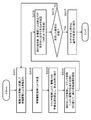
- a switching sequence from wheel drive to leg drive executed by the traveling robot 100 of the present disclosure will be described with reference to the flowchart shown in FIG. 9.
- the process according to the flowchart shown in FIG. 9 can be executed by the control unit (data processing unit) of the traveling robot 100 according to a program stored in the storage unit of the traveling robot 100, for example.
- it can be performed as a program execution process by a processor such as a CPU having a program execution function.
- the processing of each step of the flow shown in FIG. 9 will be described below.
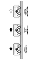
- Step S201 First, in step S201, the control unit of the traveling robot 100 of the present disclosure transmits the driving force of an actuator such as a motor to the wheels 102 and executes traveling by driving the wheels. This state is the wheel drive traveling state shown in FIG. 10 (S201).
- Step S202 the control unit executes acceleration processing by driving the wheels.
- the process of increasing the rotation speed of the wheel 102 is executed to execute the acceleration process of the traveling robot.
- This process corresponds to the process in the wheel drive traveling acceleration period from time t1 to t2 described above with reference to FIG.
- This state is the acceleration state by the wheel drive shown in FIG. 10 (S202). Even in this state, the driving force of the actuator such as the motor is transmitted to the wheels 102, and the traveling by driving the wheels is continued.
- Step S203 After the acceleration process in step S202, the control unit next controls the clutch 103 in step S203 to switch the transmission destination of the driving force of the actuator such as the motor from the wheel 102 to the leg 101.
- This processing corresponds to the processing in the first half of the gliding state by the non-driving wheels between times t2 and t3 described above with reference to FIG. Further, this state is the wheel drive stopped state shown in FIG. 10 (S203). During this time, the driving force of the actuator such as the motor is switched from the wheel 102 to the leg 101. During this switching period, the traveling robot 100 is in a gliding state due to the wheels 102 to which the driving force is not supplied.
- Step S204 When the clutch control in step S203, that is, the switching of the transmission destination of the driving force of the actuator such as the motor from the wheel 102 to the leg 101 is completed, the control unit then releases the leg 101 from the lock mechanism 104 in step S204. Further, the grounding process of the leg 101 is started by the driving force of an actuator such as a motor. This process corresponds to the latter half process of the sliding state by the non-driving wheels at the times t2 to t3 described above with reference to FIG.
- this state is the state where the grounding process by the leg drive shown in FIG. 11 (S204) is started. During this period, the driving force of the actuator such as the motor is transmitted to the leg 101, and this driving force is used for the movement process of the leg 101 necessary for the grounding of the leg 101. Therefore, the traveling robot 100 is in a sliding state due to the wheels 102 to which the driving force is not supplied.
- Steps S205 to S206 the control unit confirms that the leg 101 is in contact with the ground, and further determines whether or not stable driving is possible by driving the leg 101. Specifically, for example, for each of the four legs, contact and separation with respect to the traveling surface are executed on a trial basis, and it is determined whether stable leg drive traveling is possible. It should be noted that this process is executed in a gliding state by non-driving wheels with the wheels 102 grounded.
- step S207 When it is determined that stable leg drive traveling is not possible, the process returns to step S201, and wheel drive is switched. On the other hand, when it is determined that stable leg drive traveling is possible, the process proceeds to step S207.
- steps S205 to S206 also corresponds to the processing of the latter half of the sliding state by the non-driving wheels at the times t2 to t3 described above with reference to FIG. That is, the traveling robot 100 is in a gliding state by the wheels 102 to which the driving force is not supplied.
- Step S207 When it is determined in steps S205 to S206 that stable leg drive traveling is possible, the control unit raises the robot in step S207 to start normal leg drive traveling.
- This processing corresponds to the processing of the leg drive traveling state from time t3 described above with reference to FIG.
- This state is the leg drive traveling state shown in FIG. 11 (S207).
- the driving force of an actuator such as a motor is transmitted to the wheels 102, and the traveling robot 100 travels by driving the wheels.
- the traveling robot 100 of the present disclosure performs acceleration processing by the wheels 102, for example, before switching the transmission destination of the driving force (wheel to leg) processing by clutch control, unlocking the leg 101, and grounding processing. Acceleration is performed by increasing the rotation speed of the wheel 102. This acceleration process reduces the influence of deceleration that occurs during the process of switching the driving force transmission destination by the clutch control and the process of landing the legs, and makes the speed at the start of the leg drive travel almost the same as the speed at the wheel drive travel. It is possible to maintain the speed. That is, the leg drive traveling can be started without causing a large speed reduction.
- the traveling robot 100 having four legs 101 and four wheels 102 has four legs and four drive wheels has been described as an example.
- the processing of the present disclosure is applicable not only to a traveling robot having four legs and four driving wheels but also to various traveling robots having different numbers of legs and wheels.
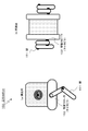
- the traveling robot 120 shown in FIG. 12 has a three-wheel configuration in which two drive wheels 122 are driven by an actuator such as a motor, and non-drive wheels 123 to which the driving force of the actuator is not transmitted are provided. There are four legs 121, and the driving force of the actuator is transmitted to all of them.
- the traveling robot 150 shown in FIG. 13 has a configuration in which two drive crawlers (caterpillars) 152 driven by an actuator such as a motor are provided.
- the number of legs 151 is two, and the legs 151 are driven by the driving force of the actuator.
- the processing of the present disclosure is applicable not only to a traveling robot having four legs and four driving wheels but also to various traveling robots having different numbers of legs and wheels.
- the traveling surface of the traveling robot 100 has been described as a plane, but the traveling surface of the traveling robot 100 is not limited to a plane.
- An operation example of the traveling robot 100 when the traveling surface is not a plane will be described with reference to FIG.
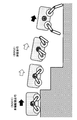
- FIG. 14 shows an example in which the traveling surface has a stepped shape and the traveling robot 100 descends the stepped traveling surface.
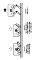
- step S301 the traveling robot 100 travels on the uppermost stage of the stairs by driving the wheels. It is assumed that wheel drive traveling is switched to leg drive traveling in the process of going down the stairs.
- the traveling robot 100 moves to the gliding state as shown in step S302 of the figure without contacting the surface of the stairs, which is the traveling surface, and then uses the legs 101 at the bottom of the stairs. Land and start driving with leg drive.
- the suppressed acceleration control is performed in consideration of the influence of the acceleration due to the fall.
- the traveling robot 100 calculates the fall distance and the gliding time based on the information detected by the sensor, calculates the level of the required acceleration processing, and executes the acceleration processing.
- FIG. 15 is an example in which the traveling robot 100 has a staircase-shaped traveling surface as in FIG. 14, but the traveling robot 100 climbs the staircase-shaped traveling surface.
- step S321 the traveling robot 100 is leg-driving at the bottom of the stairs. In the process of going up the stairs, leg drive traveling is switched to wheel drive traveling.
- the traveling robot 100 jumps as shown in step S322 in the figure without using the surface of the stairs, which is the traveling surface, to travel, and lands on the wheels 102 at the top of the stairs. Wheels are started to drive. In the acceleration process at the time of switching the drive in this case, greater acceleration control is performed in consideration of the influence of deceleration due to the jump process.
- the traveling robot 100 calculates the height of the jump and the gliding time based on the information detected by the sensor, calculates the level of the required acceleration processing, and executes the acceleration processing.
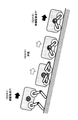
- FIG. 16 shows an example in which the traveling surface is a slope and the traveling robot 100 descends the slope.
- step S341 the traveling robot 100 is leg driven to travel down a slope.
- the leg drive traveling is switched to the wheel drive traveling.
- the traveling robot 100 shifts to the wheel-driven traveling in step S343 after shifting to the sliding state by the non-driving wheels as shown in step S342 in the process of going down the slope which is the traveling surface.
- the suppressed acceleration control is performed in consideration of the influence of the acceleration due to the fall on the slope.
- the traveling robot 100 calculates the fall distance and the gliding time on a slope based on the detection information from the sensor, calculates the level of the required acceleration processing, and executes the acceleration processing.
- FIG. 17 shows an example in which the traveling surface is a slope, but the traveling robot 100 climbs a slope.
- the traveling robot 100 is leg-driven so as to travel up a slope. It is assumed that leg drive traveling is switched to wheel drive traveling in the course of climbing the slope.
- the traveling robot 100 shifts to a gliding state by non-driving wheels as shown in step S362 in the process of climbing a slope which is a traveling surface, and then shifts to wheel driving traveling in step S363.
- larger acceleration control is performed in consideration of the influence of deceleration due to climbing a slope.
- the traveling robot 100 calculates the height of climbing up a slope and the gliding time of non-driving wheels based on the information detected by the sensor, calculates the required level of acceleration processing, and executes the acceleration processing.
- the traveling robot of the present disclosure performs control according to various traveling surfaces.
- acceleration processing such as kicking operation is executed at the end of leg drive traveling so that the speed at the start of wheel drive traveling substantially matches the speed at the time of leg drive traveling.
- the wheel rotation speed is controlled at the end of wheel drive traveling so that the speed at the start of leg drive traveling substantially matches the speed at the time of wheel drive traveling.
- FIG. 18 is a block diagram showing a configuration example of the traveling robot 100 of the present disclosure.
- the traveling robot 100 has a control unit 201, an input unit 202, an output unit 203, a sensor group 204, a drive unit 205, a communication unit 206, and a storage unit 207.
- the control unit 201 controls processing executed by the traveling robot 100. For example, the processing according to the control program stored in the storage unit 207 is executed.
- the control unit 201 has a processor having a program execution function.
- the input unit 202 is an interface that allows a user to input various data, and is configured by a touch panel, a code reading unit, various switches, and the like.
- the output unit 203 is a speaker that outputs an alert or a sound, a display that outputs an image, and an output unit that outputs a light or the like.
- the sensor group 204 includes various sensors such as a camera, a microphone, a radar, and a distance sensor.
- the drive unit 205 is configured by an actuator such as a motor that is a drive unit of wheels and legs for moving the traveling robot 100, a direction control mechanism, and the like.
- the communication unit 206 executes communication processing with, for example, the management server and external devices such as external sensors.
- the storage unit 207 stores travel route information, program information executed by the control unit 201, and the like.
- the technology disclosed in this specification may have the following configurations.
- the control unit is A traveling robot that executes traveling speed control before drive switching so that the traveling speed after drive switching becomes substantially equal to the traveling speed before drive switching when switching between leg drive and wheel drive.
- the control unit is The traveling robot according to (1), wherein when the drive is switched between leg drive and wheel drive, the wheels are set to a sliding movement state in which the wheels slide in a non-driving state.
- the control unit is When the drive is switched from the leg drive to the wheel drive, the leg drive mode is executed at the time of executing the leg drive before the drive switching so that the traveling speed by the wheel drive after the drive switching is substantially equal to the traveling speed by the leg drive before the drive switching.
- the traveling robot according to (1) or (2), which changes the acceleration process and executes the acceleration process.
- the control unit is The traveling robot according to (3), wherein a kicking motion by the leg is executed as the acceleration process.
- the control unit is When the drive is switched from the wheel drive to the leg drive, the wheel drive mode is set at the time of executing the wheel drive before the drive switching so that the traveling speed by the leg drive after the drive switching is substantially equal to the travel speed by the wheel drive before the drive switching.
- the traveling robot according to any one of (1) to (4), which changes the acceleration processing and executes the acceleration processing.
- the control unit is As the acceleration processing, the traveling robot according to (5), which executes control to increase the rotation speed of the wheels.
- the traveling robot is Having a locking mechanism for the legs
- the control unit is The traveling robot according to any one of (1) to (6), which executes a process of maintaining the leg in a fixed state by the lock mechanism when the wheels are driven.
- the control unit is When switching from leg drive to wheel drive, The traveling robot according to any one of (1) to (7), wherein the driving force from the driving unit is used for a leg moving process for fixing the leg to a lock mechanism.
- the control unit is Acceleration control at the time of leg drive execution before drive switching, which is executed at the time of drive switching from leg drive to wheel drive,
- the leg movement process of fixing the leg to the lock mechanism and the process of switching the transmission destination of the driving force of the drive unit by the clutch from the leg to the wheel are executed in consideration of the speed reduction within the execution period (1) to ( 8)
- the traveling robot according to any one of the above.
- the control unit is Acceleration control at the time of wheel drive execution before drive switching, which is executed at the time of drive switching from wheel drive to leg drive, It is executed in consideration of a speed reduction within the execution period of the process of switching the transmission destination of the driving force of the drive unit by the clutch from the wheel to the leg and the leg moving process of unlocking the leg and grounding (1).
- a traveling robot according to any one of (9) to (9).
- a traveling robot control method executed by a traveling robot The traveling robot is A drive unit and a clutch that switches the transmission destination of the drive force of the drive unit, Legs and wheels driven by the driving force of the driving unit, Has a controller, The control unit, A traveling robot control method for executing traveling speed control before drive switching so that the traveling speed after drive switching is substantially equal to the traveling speed before drive switching at the time of drive switching between leg drive and wheel drive.
- a program for executing traveling robot control in a traveling robot is A drive unit and a clutch that switches the transmission destination of the drive force of the drive unit, Legs and wheels driven by the driving force of the driving unit, Has a controller,
- the program in the control unit, A program that executes traveling speed control before drive switching so that the traveling speed after drive switching is approximately equal to the traveling speed before drive switching when drive switching between leg drive and wheel drive.
- the series of processes described in the specification can be executed by hardware, software, or a composite configuration of both.
- the program in which the processing sequence is recorded is installed in the memory in the computer incorporated in the dedicated hardware and executed, or the program is stored in the general-purpose computer capable of executing various processing. It can be installed and run.
- the program can be recorded in a recording medium in advance.
- the program can be received via a network such as LAN (Local Area Network) or the Internet and installed in a recording medium such as a built-in hard disk.
- system in the present specification is a logical set configuration of a plurality of devices, and is not limited to one in which the devices of the respective configurations are in the same housing.
- a traveling robot that performs switching traveling between leg drive and wheel drive, it is possible to suppress speed reduction when switching between leg drive and wheel drive.
- it has a drive unit, a clutch that switches the transmission destination of the drive force of the drive unit, legs and wheels that are driven by the drive force of the drive unit, and a control unit.
- the control unit executes the traveling speed control before the drive switching so that the traveling speed after the drive switching becomes substantially equal to the traveling speed before the drive switching.
- the control unit sets the wheel to the sliding movement state in which the wheel slides in the non-driving state at the time of switching the drive between the leg drive and the wheel drive.
- acceleration processing is executed before drive switching so that the traveling speed after drive switching becomes substantially equal to the traveling speed before drive switching.
- traveling robot 101 leg 102 wheel 103 clutch 104 locking mechanism 120 traveling robot 121 leg 122 driving wheel 123 non-driving wheel 150 traveling robot 151 leg 152 driving crawler (caterpillar) 201 control unit 202 input unit 203 output unit 204 sensor group 205 drive unit 206 communication unit 207 storage unit
Landscapes
- Engineering & Computer Science (AREA)
- Mechanical Engineering (AREA)
- Chemical & Material Sciences (AREA)
- Combustion & Propulsion (AREA)
- Transportation (AREA)
- Radar, Positioning & Navigation (AREA)
- Aviation & Aerospace Engineering (AREA)
- Remote Sensing (AREA)
- Physics & Mathematics (AREA)
- General Physics & Mathematics (AREA)
- Automation & Control Theory (AREA)
- Robotics (AREA)
- Manipulator (AREA)
- Control Of Position, Course, Altitude, Or Attitude Of Moving Bodies (AREA)
Abstract
L'invention concerne, dans un robot mobile qui commute entre un entraînement par jambe et un entraînement par roue pour se déplacer, la suppression d'une réduction de vitesse lors d'une commutation entre un entraînement par jambe et un entraînement par roue. La présente invention comprend une unité d'entraînement, un embrayage qui commute la destination de la transmission pour la force d'entraînement de l'unité d'entraînement, une jambe et une roue qui sont entraînées par la force d'entraînement de l'unité d'entraînement, et une unité de commande. Au moment d'une commutation d'entraînement entre un entraînement par jambe et un entraînement par roue, l'unité de commande effectue une commande de vitesse de déplacement avant la commutation d'entraînement, de telle sorte que la vitesse de déplacement après la commutation d'entraînement sera presque égale à la vitesse de déplacement avant la commutation d'entraînement. Au moment d'une commutation d'entraînement entre un entraînement par jambe et un entraînement par roue, l'unité de commande met la roue dans un état de mouvement de glissement, dans lequel celle-ci est amenée à glisser dans un état non entraîné. Au moment d'une commutation d'entraînement, un processus d'accélération est effectué avant la commutation d'entraînement, de telle sorte que la vitesse de déplacement après la commutation d'entraînement sera presque égale à la vitesse de déplacement avant la commutation d'entraînement.
Priority Applications (2)
| Application Number | Priority Date | Filing Date | Title |
|---|---|---|---|
| CN201980091519.6A CN113453847A (zh) | 2019-02-13 | 2019-12-24 | 行进机器人、行进机器人控制方法和程序 |
| US17/428,038 US20220106001A1 (en) | 2019-02-13 | 2019-12-24 | Traveling robot, traveling robot control method, and program |
Applications Claiming Priority (2)
| Application Number | Priority Date | Filing Date | Title |
|---|---|---|---|
| JP2019-023211 | 2019-02-13 | ||
| JP2019023211A JP2020134999A (ja) | 2019-02-13 | 2019-02-13 | 走行ロボット、および走行ロボット制御方法、並びにプログラム |
Publications (1)
| Publication Number | Publication Date |
|---|---|
| WO2020166211A1 true WO2020166211A1 (fr) | 2020-08-20 |
Family
ID=72044648
Family Applications (1)
| Application Number | Title | Priority Date | Filing Date |
|---|---|---|---|
| PCT/JP2019/050492 Ceased WO2020166211A1 (fr) | 2019-02-13 | 2019-12-24 | Robot mobile, procédé de commande d'un robot mobile, et programme |
Country Status (4)
| Country | Link |
|---|---|
| US (1) | US20220106001A1 (fr) |
| JP (1) | JP2020134999A (fr) |
| CN (1) | CN113453847A (fr) |
| WO (1) | WO2020166211A1 (fr) |
Cited By (6)
| Publication number | Priority date | Publication date | Assignee | Title |
|---|---|---|---|---|
| CN113562088A (zh) * | 2021-07-21 | 2021-10-29 | 河南工业贸易职业学院 | 一种多传感器移动机器人 |
| CN115214817A (zh) * | 2022-07-29 | 2022-10-21 | 南京信息工程大学 | 一种可滑行的四足机器人 |
| CN115447690A (zh) * | 2021-06-09 | 2022-12-09 | 腾讯科技(深圳)有限公司 | 一种机械腿和机器人 |
| JP2023010242A (ja) * | 2021-07-09 | 2023-01-20 | 日本精工株式会社 | 駆動制御装置、駆動装置、車輪及び車両 |
| WO2023149355A1 (fr) * | 2022-02-02 | 2023-08-10 | 川崎重工業株式会社 | Robot quadrupède |
| WO2024202490A1 (fr) * | 2023-03-24 | 2024-10-03 | ソニーグループ株式会社 | Corps mobile |
Families Citing this family (8)
| Publication number | Priority date | Publication date | Assignee | Title |
|---|---|---|---|---|
| US11548373B1 (en) * | 2018-12-10 | 2023-01-10 | Amazon Technologies, Inc. | Thermal management for a delivery autonomous ground vehicle |
| JPWO2023013113A1 (fr) * | 2021-08-02 | 2023-02-09 | ||
| CN115056880B (zh) * | 2022-06-10 | 2024-08-02 | 佛山科学技术学院 | 一种多运动态机器人的运动态切换控制方法 |
| CN115123418B (zh) * | 2022-06-30 | 2024-01-16 | 杭州云深处科技有限公司 | 一种用于四足机器人的轮腿更换机构及更换方法 |
| KR102868444B1 (ko) * | 2022-12-09 | 2025-10-02 | 박기범 | 농업용 전동 운반차 |
| US20240351710A1 (en) * | 2023-04-19 | 2024-10-24 | Hyundai Motor Company | Hybrid vehicle for use in lunar exploration |
| CN116620444B (zh) * | 2023-05-26 | 2025-08-12 | 国科卫华(天津)智能科技有限公司 | 一种六驱可重构机器人 |
| CN117302380A (zh) * | 2023-10-27 | 2023-12-29 | 北京晶品特装科技股份有限公司 | 一种具有摆腿的轮式机器人底盘装置及机器人 |
Citations (3)
| Publication number | Priority date | Publication date | Assignee | Title |
|---|---|---|---|---|
| JPS6261485U (fr) * | 1985-10-04 | 1987-04-16 | ||
| JPS63275486A (ja) * | 1987-04-30 | 1988-11-14 | Kobe Steel Ltd | 移動装置 |
| US7017687B1 (en) * | 2002-11-21 | 2006-03-28 | Sarcos Investments Lc | Reconfigurable articulated leg and wheel |
Family Cites Families (4)
| Publication number | Priority date | Publication date | Assignee | Title |
|---|---|---|---|---|
| JP4590639B2 (ja) * | 2006-09-04 | 2010-12-01 | 国立大学法人 新潟大学 | 脚型車輪型兼用移動装置 |
| JP2008260117A (ja) * | 2007-03-16 | 2008-10-30 | Nsk Ltd | 脚車輪型ロボット及び脚車輪装置 |
| CN104608837B (zh) * | 2015-01-16 | 2017-04-26 | 燕山大学 | 轮腿混合式四足机器人 |
| CN106240669B (zh) * | 2016-07-27 | 2018-06-26 | 江苏安格尔机器人有限公司 | 机器人行走装置 |
-
2019
- 2019-02-13 JP JP2019023211A patent/JP2020134999A/ja active Pending
- 2019-12-24 US US17/428,038 patent/US20220106001A1/en not_active Abandoned
- 2019-12-24 WO PCT/JP2019/050492 patent/WO2020166211A1/fr not_active Ceased
- 2019-12-24 CN CN201980091519.6A patent/CN113453847A/zh not_active Withdrawn
Patent Citations (3)
| Publication number | Priority date | Publication date | Assignee | Title |
|---|---|---|---|---|
| JPS6261485U (fr) * | 1985-10-04 | 1987-04-16 | ||
| JPS63275486A (ja) * | 1987-04-30 | 1988-11-14 | Kobe Steel Ltd | 移動装置 |
| US7017687B1 (en) * | 2002-11-21 | 2006-03-28 | Sarcos Investments Lc | Reconfigurable articulated leg and wheel |
Cited By (10)
| Publication number | Priority date | Publication date | Assignee | Title |
|---|---|---|---|---|
| CN115447690A (zh) * | 2021-06-09 | 2022-12-09 | 腾讯科技(深圳)有限公司 | 一种机械腿和机器人 |
| JP2023010242A (ja) * | 2021-07-09 | 2023-01-20 | 日本精工株式会社 | 駆動制御装置、駆動装置、車輪及び車両 |
| JP7721993B2 (ja) | 2021-07-09 | 2025-08-13 | 日本精工株式会社 | 駆動制御装置、駆動装置、車輪及び車両 |
| CN113562088A (zh) * | 2021-07-21 | 2021-10-29 | 河南工业贸易职业学院 | 一种多传感器移动机器人 |
| WO2023149355A1 (fr) * | 2022-02-02 | 2023-08-10 | 川崎重工業株式会社 | Robot quadrupède |
| JP2023112851A (ja) * | 2022-02-02 | 2023-08-15 | 川崎重工業株式会社 | 4足歩行ロボット |
| JP7813593B2 (ja) | 2022-02-02 | 2026-02-13 | 川崎重工業株式会社 | 4足歩行ロボット |
| CN115214817A (zh) * | 2022-07-29 | 2022-10-21 | 南京信息工程大学 | 一种可滑行的四足机器人 |
| CN115214817B (zh) * | 2022-07-29 | 2023-04-25 | 南京信息工程大学 | 一种可滑行的四足机器人 |
| WO2024202490A1 (fr) * | 2023-03-24 | 2024-10-03 | ソニーグループ株式会社 | Corps mobile |
Also Published As
| Publication number | Publication date |
|---|---|
| JP2020134999A (ja) | 2020-08-31 |
| CN113453847A (zh) | 2021-09-28 |
| US20220106001A1 (en) | 2022-04-07 |
Similar Documents
| Publication | Publication Date | Title |
|---|---|---|
| WO2020166211A1 (fr) | Robot mobile, procédé de commande d'un robot mobile, et programme | |
| US11378953B2 (en) | Autoscrubber convertible between manual and autonomous operation | |
| JP4511344B2 (ja) | 使用者によって推進される車椅子および車椅子を推進する方法 | |
| US20070272463A1 (en) | Omni-directional robot cleaner | |
| JP5761347B2 (ja) | 倒立型移動体制御装置、その制御方法及びプログラム | |
| JPWO2013038998A1 (ja) | 自走ロボットおよび自走台車 | |
| US11975787B2 (en) | Control device for mobile body | |
| WO2018074117A1 (fr) | Dispositif mobile et système de gestion de dispositif mobile | |
| JP2010160735A (ja) | 移動ロボット、走行計画マップ生成方法、管理システム | |
| JP6759734B2 (ja) | 履帯式走行体 | |
| JP2024068767A (ja) | カートロボット | |
| JP4327566B2 (ja) | 前輪の接地と浮遊が切換え可能な走行体および走行状態切換え方法 | |
| US9139224B2 (en) | Inverted pendulum type vehicle | |
| JP3022354B2 (ja) | 移動車に任意の並行移動運動と任意の回転運動を組み合せた運動を実行させるための方法 | |
| JP7243722B2 (ja) | 制御装置および制御方法 | |
| JP2006085369A (ja) | 移動体装置及びその制御方法 | |
| JP6823147B1 (ja) | 移動体 | |
| Adachi et al. | Development of a leg-wheel hybrid mobile robot and its step-passing algorithm | |
| JP2024090520A (ja) | カートロボット | |
| JP7207316B2 (ja) | 情報処理装置、自律型移動装置、および方法、並びにプログラム | |
| JP7527950B2 (ja) | 制御装置及びプログラム | |
| Strah et al. | Autonomous stair climbing of a wheeled double inverted pendulum | |
| JP2024089312A (ja) | カートロボット | |
| KR20200072032A (ko) | 지상 이동체 및 그의 제어 방법 | |
| WO2024101205A1 (fr) | Robot de chariot |
Legal Events
| Date | Code | Title | Description |
|---|---|---|---|
| 121 | Ep: the epo has been informed by wipo that ep was designated in this application |
Ref document number: 19915170 Country of ref document: EP Kind code of ref document: A1 |
|
| NENP | Non-entry into the national phase |
Ref country code: DE |
|
| 122 | Ep: pct application non-entry in european phase |
Ref document number: 19915170 Country of ref document: EP Kind code of ref document: A1 |