WO2020170710A1 - 高強度鋼板、熱延鋼板の製造方法、冷延フルハード鋼板の製造方法および高強度鋼板の製造方法 - Google Patents
高強度鋼板、熱延鋼板の製造方法、冷延フルハード鋼板の製造方法および高強度鋼板の製造方法 Download PDFInfo
- Publication number
- WO2020170710A1 WO2020170710A1 PCT/JP2020/002392 JP2020002392W WO2020170710A1 WO 2020170710 A1 WO2020170710 A1 WO 2020170710A1 JP 2020002392 W JP2020002392 W JP 2020002392W WO 2020170710 A1 WO2020170710 A1 WO 2020170710A1
- Authority
- WO
- WIPO (PCT)
- Prior art keywords
- less
- steel sheet
- martensite
- average
- temperature
- Prior art date
- Legal status (The legal status is an assumption and is not a legal conclusion. Google has not performed a legal analysis and makes no representation as to the accuracy of the status listed.)
- Ceased
Links
Classifications
-
- C—CHEMISTRY; METALLURGY
- C21—METALLURGY OF IRON
- C21D—MODIFYING THE PHYSICAL STRUCTURE OF FERROUS METALS; GENERAL DEVICES FOR HEAT TREATMENT OF FERROUS OR NON-FERROUS METALS OR ALLOYS; MAKING METAL MALLEABLE, e.g. BY DECARBURISATION OR TEMPERING
- C21D9/00—Heat treatment, e.g. annealing, hardening, quenching or tempering, adapted for particular articles; Furnaces therefor
- C21D9/46—Heat treatment, e.g. annealing, hardening, quenching or tempering, adapted for particular articles; Furnaces therefor for sheet metals
-
- C—CHEMISTRY; METALLURGY
- C22—METALLURGY; FERROUS OR NON-FERROUS ALLOYS; TREATMENT OF ALLOYS OR NON-FERROUS METALS
- C22C—ALLOYS
- C22C38/00—Ferrous alloys, e.g. steel alloys
-
- C—CHEMISTRY; METALLURGY
- C22—METALLURGY; FERROUS OR NON-FERROUS ALLOYS; TREATMENT OF ALLOYS OR NON-FERROUS METALS
- C22C—ALLOYS
- C22C38/00—Ferrous alloys, e.g. steel alloys
- C22C38/14—Ferrous alloys, e.g. steel alloys containing titanium or zirconium
-
- C—CHEMISTRY; METALLURGY
- C22—METALLURGY; FERROUS OR NON-FERROUS ALLOYS; TREATMENT OF ALLOYS OR NON-FERROUS METALS
- C22C—ALLOYS
- C22C38/00—Ferrous alloys, e.g. steel alloys
- C22C38/60—Ferrous alloys, e.g. steel alloys containing lead, selenium, tellurium, or antimony, or more than 0.04% by weight of sulfur
Definitions
- the present invention relates to a high-strength steel plate, a hot-rolled steel plate manufacturing method, a cold-rolled full-hard steel plate manufacturing method, and a high-strength steel plate manufacturing method.
- High-strength steel sheets used for automobile structural members and reinforcing members are required to have excellent workability.
- workability in processing a component having a complicated shape, not only individual characteristics such as elongation and hole expandability are excellent, but also all of them are required to be excellent.
- press-formed parts are often combined by resistance welding (spot welding), and may be welded to hot-dip galvanized steel sheets.
- spot welding spot welding
- zinc may melt on the surface of the steel sheet during spot welding, and residual stress may be generated in the vicinity of the welded portion, which may cause liquid metal brittleness and cracks in the steel sheet.
- the high-strength steel plate is a non-galvanized steel plate, if the other steel plate to be welded is a galvanized steel plate, the zinc will melt.
- spot welding since stress is applied to the welded portion in order to maintain the rigidity of the entire automobile body, it is feared that hydrogen that enters from the use environment may cause delayed fracture.
- the high-strength steel sheet has workability, cracking of the resistance weld portion due to liquid metal brittleness and delayed fracture does not easily occur, and it has excellent resistance to cracking of the resistance weld portion. Need to be present.
- Patent Document 1 discloses a technique of improving surface crack resistance during resistance welding by controlling the contents of Si, Al, and Mn.
- the present invention has been developed in view of the above circumstances, and an object of the present invention is to provide a high-strength steel sheet excellent in workability and crack resistance of resistance welded portions.
- the high-strength steel sheet in the present invention is a steel sheet having a tensile strength (TS) of 780 MPa or more.
- TS tensile strength
- excellent workability means having both excellent elongation and excellent hole expandability.
- excellent elongation and excellent hole expandability can mean those having an elongation of 14% or more and a hole expansion rate of 35% or more, respectively, in the tests described below.
- the resistance to cracking in resistance welding means that the occurrence of cracking during resistance welding and the occurrence of cracking in the resistance welding portion due to hydrogen in the operating environment are both suppressed.
- a predetermined angle for example, 6 degrees
- cracks did not occur in the resistance welding part, and hydrogen was added to the welded body by cathodic electrolytic charging. It can mean that no rupture is seen after a certain time.
- This invention is based on the above findings, and its gist is as follows.
- the balance has a component composition consisting of Fe and inevitable impurities, Where Mo, N, Ti and B are expressed by the formula (1): [Mo]+2 ⁇ ([Ti]-3.4 ⁇ [N])+45 ⁇ [B] ⁇ 0.20 (Here, [Mo], [Ti], [N] and [B] are the contents (mass %) of Mo, Ti, N and B, respectively, and [N] is 0 mass %.
- the ferrite has an average crystal grain size of 6 ⁇ m or less, and an average aspect ratio of 2.0 or less
- the martensite has an average crystal grain size of 5 ⁇ m or less, and an average aspect ratio of 2.0 or less
- the bainite has an average crystal grain size of 5 ⁇ m or less
- the average free path of the martensite is 8.0 ⁇ m or less, and, among the martensite, the martensite grains in which 10 or more carbides having a grain size of 0.1 ⁇ m or more exist in the martensite grains have a volume relative to the total martensite.
- the above component composition is mass% and further Cr: 0.80% or less, Cu: 0.50% or less, Ni: 0.50% or less,
- [5] A method for producing cold-rolled full-hard steel sheet, in which the hot-rolled steel sheet obtained by the production method of [4] is pickled and cold-rolled.
- the cold rolled full hard steel sheet obtained by the manufacturing method of [5] is heated to a soaking temperature of 750°C to 900°C at an average heating rate of 0.5°C/min to 5.0°C/min.
- a method for producing a high-strength steel sheet which is maintained at the temperature for 1 hour or more and then cooled to room temperature at an average cooling rate of 1.0°C/h or more and 100°C/h or less.
- a high-strength steel sheet having high tensile strength, excellent workability (excellent elongation and hole expandability), and excellent resistance weld cracking resistance is provided together with its manufacturing method.
- the manufacturing method of a hot-rolled steel plate and the manufacturing method of a cold-rolled full hard steel plate which can bring about the said high strength steel plate are provided.
- C 0.05% or more and 0.18% or less C is an element effective in strengthening the steel sheet, and contributes to the formation of the second phase (including pearlite, bainite, and martensite) other than the first phase, ferrite. It is an important element. If the C content is less than 0.05%, it is difficult to secure the necessary volume fraction of pearlite, bainite, and martensite, and it is difficult to obtain the desired strength. Therefore, the content is 0.05% or more. It is preferably 0.075% or more. When the content of C is excessive, the hardness after resistance welding becomes hard, the toughness at the time of resistance welding decreases, and the crack resistance of the resistance welding part deteriorates.
- martensite with high hardness which is insufficient in the formation of carbides, becomes excessive, so that good hole expandability and delayed fracture properties cannot be obtained. Further, the volume fraction of martensite increases, making it difficult to secure the volume fraction of ferrite, and the elongation decreases. Therefore, its content should be 0.18% or less. It is preferably 0.16% or less.
- Si 0.8% or less Si is an element that contributes to the strengthening by strengthening the solid solution of ferrite.
- the content is excessive, the toughness during resistance welding decreases and the resistance to cracking of the resistance weld becomes poor. to degrade. Further, martensite in which a predetermined amount of carbide is formed cannot be obtained, and good hole expandability and delayed fracture properties cannot be obtained. Therefore, the content is 0.8% or less. It is preferably 0.50% or less. It is more preferably 0.30% or less. The lower limit is not particularly limited, but 0.005% or more is preferable because an extremely low Si content increases cost.
- Mn 1.5% to 3.0%
- Mn is an element that contributes to strengthening by promoting solid solution strengthening and formation of the second phase. It is also an element that stabilizes austenite and is necessary for controlling the volume fraction of the second phase. In order to obtain these effects, its content should be 1.5% or more. It is preferably 2.1% or more. More preferably, it is 2.2% or more. On the other hand, when the content is excessive, Mn bands are generated, so that the hole expandability and resistance weld cracking resistance deteriorate. Therefore, the content is 3.0% or less. It is preferably 2.6% or less.
- P 0.05% or less
- P is an element that contributes to strengthening by solid solution strengthening, but if the content is excessive, segregation to the grain boundaries becomes significant and the grain boundaries become brittle, so resistance welding Part cracking property decreases. Therefore, the content is set to 0.05% or less. It is preferably 0.04% or less.
- the lower limit is not particularly limited, but an extremely low P content increases the steelmaking cost, so 0.0005% or more is preferable.
- the content of S is 0.005% or less.
- the content is 0.005% or less. It is preferably 0.0045% or less.
- the lower limit is not particularly limited, but 0.0002% or more is preferable because an extremely low S content increases the steelmaking cost.
- Al 0.01% or more and 0.10% or less
- Al is an element necessary for deoxidation, and its content is 0.01% or more in order to obtain this effect. On the other hand, if it exceeds 0.10%, the effect is saturated, so the content is made 0.10% or less. It is preferably 0.06% or less.
- N 0.010% or less
- N is an element that forms coarse nitrides and deteriorates the hole expandability. This tendency becomes remarkable when N exceeds 0.010%. Therefore, its content is 0.010% or less. It is preferably 0.008% or less.
- the lower limit is not particularly limited, but 0.0005% or more is preferable because extremely low N conversion increases cost.
- Mo 0.05% or more and 0.50% or less
- Mo is an element that contributes to strengthening by promoting the formation of the second phase. It is an element that stabilizes austenite during annealing and is necessary for controlling the volume fraction of the second phase. Further, it is an important element in the present invention because the hardenability can be secured even if the cooling rate during annealing is low. In order to obtain these effects, the content is 0.05% or more. It is preferably 0.08% or more. On the other hand, if the content is excessive, the second phase is excessively generated, and the elongation and the hole expandability deteriorate. Therefore, its content should be 0.50% or less. It is preferably 0.43% or less.
- Ti 0.01% or more and 0.10% or less Ti is an element that contributes to strengthening by forming fine carbonitrides. It also contributes to suppressing the reaction of B, which is an essential element in the present invention, with N. Furthermore, it is an important element in the present invention because it can control the grain growth of fine carbonitrides during annealing and generate ferrite and martensite that are close to spherical. In order to obtain these effects, the content is 0.01% or more. It is preferably 0.03% or more. It is more preferably 0.04% or more. On the other hand, if Ti is added in a large amount, the elongation is significantly reduced, so the content is made 0.10% or less. It is preferably 0.09% or less.
- B 0.0002% or more and 0.0100% or less B improves the hardenability and contributes to the strengthening by promoting the formation of the second phase. It is an element that does not lower the martensite transformation start point while ensuring the hardenability. is there. In addition, segregation at grain boundaries improves grain boundary strength, which is effective for delayed fracture resistance. In order to obtain these effects, the content is 0.0002% or more. It is preferably 0.0005% or more. On the other hand, if the content is excessive, toughness is deteriorated and resistance weld cracking resistance is deteriorated. Therefore, the content is 0.0100% or less. It is preferably 0.0050% or less.
- [Mo], [Ti], [N] and [B] are the contents (mass %) of Mo, Ti, N and B, respectively, and even if [N] is 0 mass %. Good.
- the above formula (1) secures a predetermined structure, and is an index in securing strength, workability and resistance weld cracking resistance, and when the value on the left side is less than 0.20, the predetermined structure is Otherwise, it may be difficult to combine strength, workability, and resistance weld cracking resistance. Therefore, the value on the left side is 0.20 or more. It is preferably 0.21 or more. The upper limit is 1.15, and since it is difficult to secure ductility with an increase in quenching elements, it is preferably 0.85 or less.
- the high-strength steel sheet of the present invention may further contain one or more of the following components.
- V 0.06% or less
- V is an element that contributes to the strength increase by forming fine carbonitrides.
- its content is preferably 0.01% or more in order to obtain this effect. It is more preferably 0.015% or more.
- its content is 0.06% or less. It is preferably 0.055% or less.
- Nb 0.05% or less
- Nb is an element that contributes to strengthening by forming fine carbonitrides like V.
- its content is preferably 0.005% or more in order to obtain this effect. It is more preferably 0.01% or more.
- the content is set to 0.05% or less. It is preferably 0.035% or less.
- Cr 0.80% or less Cr is an element that contributes to strengthening by promoting the formation of the second phase. Further, Cr is an element that stabilizes austenite during annealing, and is effective in controlling the volume fraction of the second phase.
- its content is preferably 0.01% or more in order to obtain these effects. It is more preferably 0.05% or more.
- the content is excessive, the second phase is excessively generated, which may adversely affect elongation and bending workability, and excessively generate a surface oxide, which deteriorates galvanizability and chemical conversion treatability. Therefore, its content is 0.80% or less. It is preferably 0.65% or less.
- Cu 0.50% or less
- Cu is an element that contributes to strengthening by solid solution strengthening and also contributes to strengthening by promoting generation of the second phase.
- its content is preferably 0.05% or more in order to obtain these effects. It is more preferably 0.12% or more.
- the content if the content exceeds 0.50%, the effect is saturated, and surface defects due to Cu are likely to occur. Therefore, its content should be 0.50% or less. It is preferably 0.33% or less.
- Ni 0.50% or less
- Ni is an element that contributes to strengthening by solid solution strengthening and also contributes to strengthening by promoting generation of the second phase.
- its content is preferably 0.05% or more in order to obtain these effects. It is more preferably 0.08% or more.
- Ni is particularly effective when Cu is contained because it has an effect of suppressing surface defects caused by Cu when it is contained together with Cu.
- its content should be 0.50% or less. It is preferably 0.35% or less.
- Sb 0.02% or less
- Sb is an element that has the effect of suppressing the decarburization layer that occurs in the surface layer of the steel sheet and that contributes to the improvement of the crack resistance of the resistance weld by making the hardness distribution of the surface layer uniform.
- its content is preferably 0.002% or more in order to obtain these effects. It is more preferably 0.005% or more.
- the Sb content is 0.02% or less. It is preferably 0.015% or less.
- Ca and REM are elements that reduce the adverse effect on the hole expansibility by spheroidizing the shape of the sulfide.
- the content is preferably 0.0005% or more in order to obtain these effects. More preferably, it is 0.0008% or more.
- the content is 0.0050% or less. Preferably, it is 0.0032% or less.
- the balance other than the above is Fe and inevitable impurities.
- the unavoidable impurities include, for example, Zn, Co, Sn, Zr, etc., and the permissible ranges of these contents are: Zn: 0.01% or less, Co: 0.10% or less, Sn: 0.10% or less, Zr:0.10. % Or less.
- the microstructure is Volume fraction, 30% or more and 70% or less of ferrite, Martensite is 20% or more and 70% or less, Perlite is 10% or less (including 0%) and bainite is 20% or less (including 0%),
- the ferrite has an average crystal grain size of 6 ⁇ m or less, and an average aspect ratio of 2.0 or less
- the martensite has an average crystal grain size of 5 ⁇ m or less, and an average aspect ratio of 2.0 or less
- the bainite has an average crystal grain size of 5 ⁇ m or less
- the mean free path of the martensite is 8.0 ⁇ m or less, and, among the martensite, the martensite grains, martensite grains having a grain size of 0.1 ⁇ m or more and 10 or more carbides, the volume with respect to all martensite.
- the ratio is 50% or more.
- volume fraction such as volume fraction, average crystal grain size, aspect ratio, and mean free path:
- the volume fractions of ferrite, martensite, bainite, and pearlite were 3000 times higher than that of the steel plate after the plate thickness cross section parallel to the rolling direction was polished and corroded with 3 vol.% Nital, using SEM (scanning electron microscope) At a magnification, 10 fields of view (1 field of view is 50 ⁇ m ⁇ 40 ⁇ m) are observed at a position 1/4 in the plate thickness direction from the surface, and the area fraction is determined by the point counting method (based on ASTM E562-83 (1988)). It is measured, and the area fraction is taken as the volume fraction.
- the volume fraction thus obtained is the volume fraction of the entire hot press member.
- the microstructure granular carbides are observed, but in the calculation of the area fraction of each phase, when carbides are present in each phase, the area including the areas of these carbides is also included. The percentage. The same applies to the following.
- the average crystal grain size of ferrite, bainite, and martensite can be obtained by importing a photo in which the crystal grains of ferrite, bainite, and martensite have been identified in advance from the steel sheet micrograph using Image-Pro of Media Cybernetics. It is possible to calculate the area of each phase, calculate the circle equivalent diameter for the crystal grains of ferrite, bainite and martensite, and for each of the ferrite, bainite and martensite, it was determined by averaging the values of the circle equivalent diameter. It is a thing.
- the volume fraction of martensite grains in which 10 or more carbides having a grain size of 0.1 ⁇ m or more are present in the martensite grains is obtained as follows. After polishing the plate thickness cross section parallel to the rolling direction of the steel plate, corroding it with 3 vol.% Nital and using a TEM (transmission electron microscope) at a magnification of 20000 times, about 1/4 position from the surface in the plate thickness direction , 10 fields of view (1 field of view: 0.5 ⁇ m ⁇ 0.5 ⁇ m) were observed, 25 martensite grains were selected in descending order of average crystal grain size, and the point count method (ASTM E562-83 ( 1988)), and calculate the area fraction to obtain the volume fraction.
- TEM transmission electron microscope
- the number of carbides having a grain size of 0.1 ⁇ m or more present in the grains is counted.
- the particle size of the carbide is the equivalent circle diameter.
- the area fraction of martensite grains in which 10 or more carbides having a grain size of 0.1 ⁇ m or more exist in the grains is determined as the volume fraction.
- the mean free path of martensite is calculated by the following mathematical formula 1.
- L M Martensite mean free path
- d M Martensite mean crystal grain size
- ⁇ Circularity
- the volume fraction of ferrite If the volume fraction of ferrite exceeds 70%, it is difficult to achieve a tensile strength of 780 MPa. Therefore, the volume fraction should be 70% or less. It is preferably 65% or less. On the other hand, when the volume fraction is less than 30%, the second phase is excessively generated and voids are easily generated during punching in the hole expanding test, so that the hole expandability is deteriorated. Furthermore, if the volume fraction is less than 30%, the elongation will decrease. Therefore, the volume fraction should be 30% or more. It is preferably 35%, more preferably 40% or more.
- the average crystal grain size of ferrite is 6 ⁇ m or less.
- the lower limit is not particularly limited, it can be industrially set to 0.5 ⁇ m or more. It is preferably 5.5 ⁇ m or less, and more preferably 2 ⁇ m or more.
- the average aspect ratio of ferrite exceeds 2.0, the voids generated during punching in the hole expansion test will be easy to connect during hole expansion, and the hole expandability will deteriorate. Therefore, the average aspect ratio is 2.0 or less.
- the lower limit is 1.0, and may be 1.0. It is preferably 1.8 or less, and more preferably 1.3 or more. More preferably, it is 1.6 or less.
- the volume fraction of martensite is 20% or more in order to secure the desired strength. It is preferably at least 23%.
- the volume fraction should be 70% or less. It is preferably 65% or less, more preferably 60% or less.
- the average crystal grain size of martensite is set to 5 ⁇ m or less.
- the lower limit is not particularly limited, it can be industrially set to 0.2 ⁇ m or more. It is preferably 4.5 ⁇ m or less, and more preferably 2.5 ⁇ m or more.
- the average aspect ratio of martensite exceeds 2.0, the voids generated during punching during the hole expansion test are likely to be connected during hole expansion, resulting in poor hole expandability. Therefore, the average aspect ratio is 2.0 or less.
- the lower limit is 1.0, and may be 1.0. It is preferably 1.8 or less, and more preferably 1.3 or more.
- the martensite grains having 10 or more carbides with a grain size of 0.1 ⁇ m or more in the grain should be 50% or more in the total martensite volume fraction. If the volume fraction is less than 50%, a large amount of high-hardness martensite will be generated, and void formation will excessively increase during punching, resulting in deterioration of hole expandability. In addition, hydrogen trap sites in the resistance weld and the heat affected zone (HAZ) are insufficient, so it is difficult to obtain sufficient delayed fracture resistance. Therefore, the volume fraction should be 50% or more. It is preferably 55% or more. On the other hand, the upper limit may be 95%, preferably 90% or less.
- the mean free path of martensite exceeds 8.0 ⁇ m, void formation during punching in the hole expansion test increases excessively, resulting in deterioration of hole expandability. Furthermore, a concentration distribution of Mn, etc. occurs in the heat-affected zone (HAZ) after resistance welding, causing internal cracking during resistance welding and delayed fracture characteristics after resistance welding. Therefore, the mean free path of martensite is 8.0 ⁇ m or less.
- the mean free path can be, for example, 3.0 ⁇ m or more.
- the volume fraction should be 10% or less. It is preferably 5% or less, and may be 0%.
- Bainite Since bainite contributes to strengthening, it may be generated in the microstructure, but since it contains a high dislocation density, if the volume fraction exceeds 20%, void formation after punching in the hole expanding test increases excessively. Therefore, the hole expandability deteriorates. Therefore, the volume fraction should be 20% or less. It is preferably 15% or less, and may be 0%.
- the average grain size of bainite exceeds 5 ⁇ m, the toughness deteriorates due to the coarsening of grains during resistance welding, causing internal cracking and delayed fracture after resistance welding. Therefore, the average grain size of bainite is set to 5 ⁇ m or less.
- the lower limit is not particularly limited, it can be industrially set to 0.5 ⁇ m or more. It is preferably 4 ⁇ m or less, and more preferably 2 ⁇ m or more.
- the microstructure of the high-strength steel sheet of the present invention is basically composed of ferrite, martensite, pearlite and bainite (however, the volume fraction of pearlite and bainite may be 0%). Besides, residual austenite and unrecrystallized ferrite may be contained. Even in this case, if the ferrite, martensite, pearlite and bainite satisfy the above conditions, the object of the present invention can be achieved.
- the residual structure other than ferrite, martensite, pearlite and bainite is preferably 5% or less, more preferably 3% or less, and may be 0%.
- the high strength steel plate of the present invention may be provided with a plating layer.
- the plating layer is not particularly limited and may be, for example, either a hot dip layer or an electroplating layer, or an alloyed plating layer.
- the plating metal is not particularly limited and may be aluminum plating or the like in addition to zinc plating.
- the high strength steel plate of the present invention includes a plated steel plate.
- the plate thickness of the high-strength steel plate is not particularly limited, and can be 0.4 mm or more and 3.0 mm or less.
- the plate thickness is preferably 0.5 mm or more, more preferably 0.55 mm or more, preferably 2.8 mm or less, and more preferably 2.6 mm or less.
- the plate thickness refers to the plate thickness of the base steel plate excluding the plating layer.
- the hot rolling start temperature of the steel slab is preferably 1100°C or higher and 1300°C or lower, and after the steel slab is cast, hot rolling is performed at a temperature of 1100°C or higher and 1300°C or lower without reheating. It is preferable to start hot rolling after starting or after reheating to 1100° C. or higher and 1300° C. or lower. That is, in the present invention, after the steel slab is manufactured, the steel slab is once cooled to room temperature and then reheated. An energy-saving process such as a method of immediately rolling after heating, or a method of direct-rolling/direct rolling in which casting is followed by rolling as it is can be applied without any problem.
- the rolling reduction of the final pass of finish rolling is 12% or more, a large number of shear bands are introduced into the austenite grains, and The nucleation site of ferrite transformation increases, the structure of the hot-rolled steel sheet can be refined, the Mn band is eliminated, and the martensite in hot-rolled steel sheet, cold-rolled full-hard steel sheet, and high-strength steel sheet after annealing. It is necessary because the mean free path of can be reduced. It is also necessary for ferrite and martensite to obtain a predetermined aspect ratio.
- the rolling reduction in the final pass is 13% or more.
- the rolling reduction in the final pass is 16% or more.
- the upper limit is not particularly limited, but by increasing the hot rolling load, the plate thickness variation in the width direction of the plate becomes large, and in order to avoid deterioration in resistance weld cracking resistance, 30% The following are preferred.
- the rolling ratio of the pass immediately before the final pass 11% or more
- the strain accumulation effect is further enhanced, and a shear band is formed in the austenite grains.
- the nucleation site of ferrite transformation is further increased, and the structure of the hot-rolled steel sheet is further refined to eliminate the Mn band and reduce the mean free path of martensite. .. It is also necessary for ferrite and martensite to obtain a predetermined aspect ratio.
- the rolling reduction immediately before the final pass is 12% or more.
- the upper limit is not particularly limited, but by increasing the hot rolling load, the plate thickness variation in the width direction of the plate increases, and in order to avoid deterioration of the resistance weld cracking resistance, 16%, The following are preferred.
- Edge ratio of the pass immediately before the final pass to the final pass reduction ratio is preferably 1.1 or less.
- a predetermined aspect ratio may not be obtained for ferrite and martensite.
- the number of passes other than the final pass, the pass immediately before the final pass, and the reduction rate are not particularly limited.
- the number of passes may be two, the final pass and the pass immediately before the final pass.
- the total number of passes including these two passes may be 4 or more, for example, 5 or more, and 20 or less. It is possible and 16 or less are preferable.
- Hot rolling improves the resistance weld cracking resistance after annealing by uniformly refining the structure of the steel sheet and reducing the material anisotropy.
- the finish rolling finish temperature is set to 840°C or higher. It is preferably 870°C or higher.
- the finish rolling end temperature exceeds 950°C, the hot rolled structure becomes coarse and the crystal grains after annealing also become coarse. Therefore, the finish rolling finish temperature is set to 950°C or lower. It is preferably 930°C or lower.
- the primary cooling is performed at a primary average cooling rate of 70° C./s or more to a first cooling stop temperature of 700° C. or less.
- the primary average cooling rate is less than 70°C/s, ferrite and martensite are coarsened, so that the steel sheet structure of the hot-rolled steel sheet becomes inhomogeneous and the hole expandability, resistance weld cracking resistance and delayed fracture property are descend.
- the primary average cooling temperature is 70°C/s or higher. It is preferably 75°C/s or more.
- the upper limit of the first average cooling temperature is not particularly limited, but may be 150° C./s or less, for example. If the first cooling stop temperature in primary cooling exceeds 700°C, the structure of the hot-rolled steel sheet becomes coarse and the final microstructure becomes coarse, resulting in poor hole expansibility, resistance to weld cracking and delayed fracture properties. To do. Therefore, the first cooling stop temperature is set to 700°C or lower. It is preferably 680°C or lower. The first cooling stop temperature is not particularly limited as long as it is higher than the winding start temperature of 610° C. or lower, and may be 630° C. or higher, for example.
- the secondary average cooling rate of 5° C./s or more and 50° C./s or less is used to cool from the cooling stop temperature to the winding start temperature of 610° C. or less.
- the second average cooling rate is 5°C/s or more, preferably 8°C/s or more.
- the second average cooling rate can be 45°C/s or less, preferably 40°C/s or less.
- the temperature is cooled to a winding start temperature of 610° C. or lower, and then winding is started.
- the lower limit of the winding start temperature is not particularly limited, but the temperature at the time of winding becomes too low, hard martensite is excessively generated, from the viewpoint of avoiding an increase in cold rolling load, 300 C. or higher is preferable.
- -Winding start temperature 610°C or less
- the winding start temperature is preferably 600° C. or lower.
- the winding start temperature is preferably 300°C or higher.
- the steel plate After the above-mentioned winding, the steel plate is cooled by air cooling etc. and used for the production of the cold rolled full hard steel plate described below.
- the hot rolled steel sheet is an intermediate product to be traded, the hot rolled steel sheet is usually traded in a cooled state after winding.
- the plate thickness of the hot-rolled steel sheet is not particularly limited, and is preferably 0.8 mm or more and 5.0 mm or less, more preferably 1.1 mm or more and 4.5 mm or less.
- the cold rolled full hard steel sheet can be manufactured by cold rolling the hot rolled steel sheet obtained by the above manufacturing method.
- the cold-rolled full-hard steel sheet refers to a cold-rolled steel sheet that is used for various purposes in a state where no annealing treatment is performed after cold rolling, that is, in a full-hard state.
- Various applications include production of high-strength steel sheets, and high-strength steel sheets may be continuously produced after production of cold-rolled full-hard steel sheets.
- the cold rolling conditions can be appropriately set, for example, from the viewpoint of desired thickness and the like.
- the reduction ratio of cold rolling is usually 30% or less.
- Pickling is performed before the cold rolling in order to remove the scale on the surface of the hot rolled steel sheet.
- the pickling conditions can be set appropriately.
- the plate thickness of the cold rolled full hard steel plate is not particularly limited, and is preferably 0.4 mm or more and 3.0 mm or less, more preferably 0.5 mm or more and 2.8 mm or less.
- the high-strength steel plate can be manufactured by heating and cooling (annealing) a cold rolled full hard steel plate.
- This annealing step is a step for advancing the recrystallization of ferrite and forming fine ferrite, martensite and bainite in the microstructure for increasing the strength, and is 0.5°C/min or more and 5.0°C/min or less. It is heated to a soaking temperature of 750° C. or higher and 900° C. or lower at an average heating rate, held at the temperature for 1 hour or longer, and then cooled to room temperature at an average cooling rate of 1.0° C./h or more and 100° C./h or less.
- the average heating rate is 5.0°C/min or less. It is preferably 4.5°C/min or less.
- the average heating rate is 0.5°C/min or more. It is preferably 1.0°C/min or more.
- -Soaking temperature (holding temperature): 750°C or more and 900°C or less
- the soaking temperature is the temperature range that is the two-phase region of ferrite and austenite or the austenite single phase region. If the temperature is less than 750°C, the ferrite fraction increases, and it becomes difficult to secure the strength. Further, martensite in which a predetermined amount of carbide is formed cannot be obtained, and good hole expandability and good delayed fracture properties cannot be obtained. Therefore, the soaking temperature is 750°C or higher. If the soaking temperature is too high, the growth of austenite crystal grains becomes remarkable, and the crystal grains become coarse, so that the crack resistance of the resistance weld zone deteriorates. Therefore, the soaking temperature is set to 900°C or lower. It is preferably 880°C or lower.
- Soaking time 1 hour or more At the above soaking temperature, the soaking time is required to be 1 hour or more for the progress of recrystallization, spheroidization of crystal grains and austenite transformation of a part or all of the structure. .. Further, if the soaking time is less than 1 hour, the ferrite fraction increases, and it becomes difficult to secure the strength. Further, martensite in which a predetermined amount of carbide is formed cannot be obtained, and good hole expandability and good delayed fracture properties cannot be obtained. It is preferably 2 hours or more.
- the upper limit is not particularly limited, but if the soaking time is excessively long, micro segregation of Mn is promoted, and hole expandability and resistance weld cracking resistance may be deteriorated, so 100 hours or less is preferable. It is more preferably 72 hours or less.
- -Cooling conditions during annealing Cool to room temperature at an average cooling rate of 1.0°C/h or more and 100°C/h or less. After soaking, the soaking temperature to room temperature is 1.0°C/h or more and 100°C/h or less. It is necessary to cool at an average cooling rate. If the average cooling rate is less than 1.0°C/h, it is difficult to secure the strength because ferrite transformation proceeds during cooling and the volume fraction of the second phase decreases. Therefore, the average cooling rate is 1.0°C/h or more. It is preferably 1.3° C./h or more.
- the average cooling rate exceeds 100°C/h, martensite is excessively formed, the TS is lowered and the El is lowered, and the desired aspect ratio of ferrite and martensite cannot be obtained, resulting in poor hole expansibility. .. Further, martensite in which a predetermined amount of carbide is formed cannot be obtained, and good delayed fracture rupture properties cannot be obtained. Therefore, the average cooling rate is 100°C/h or less. It is preferably 73° C./h or less.
- the steel plate may be plated to form a plating layer.
- the plated layer may be either a hot-dip plated layer or an electroplated layer, or may be an alloyed plated layer.
- the plating metal is not particularly limited and may be aluminum plating or the like in addition to zinc plating.
- the high-strength steel sheet of the present invention can secure hole expandability and resistance weld cracking resistance by controlling the above-described composition and microstructure without performing plating treatment.
- Hot-dip galvanizing can be performed under normal conditions.
- the temperature of the steel sheet immersed in the plating bath is preferably (hot dip galvanizing bath temperature ⁇ 40)° C. or higher and (hot dip galvanizing bath temperature +50)° C. or lower.
- the temperature of the steel plate to be immersed in the plating bath is lower than the hot-dip galvanizing bath temperature -40°C, when the steel plate is immersed in the plating bath, part of the molten zinc solidifies and deteriorates the appearance of the plating. There is. Therefore, it is preferable to set the lower limit to (hot dip galvanizing bath temperature ⁇ 40)° C.
- zinc plating can be alloyed in the temperature range of 450°C to 600°C.
- the Fe concentration in the plating can be controlled to 7% to 15%, and the adhesion of the plating and the corrosion resistance after coating are improved.
- the temperature is lower than 450°C, alloying does not proceed sufficiently, which leads to a reduction in sacrificial anticorrosion action and a reduction in slidability. ..
- a galvanizing bath containing 0.10 mass% or more and 0.20 mass% or less of Al. After plating, wiping can be performed to adjust the basis weight of plating.
- Temper rolling may be performed after annealing.
- the preferable range of the elongation rate is 0.05% or more and 2.0% or less.
- the hot rolling heating temperature is 1250°C and the finish rolling finish temperature (FDT) is finished under the conditions shown in Table 2.
- Hot rolling was performed with a total of 7 passes of rolling to obtain a hot rolled steel sheet.
- the first cooling stop temperature at the primary average cooling rate (cold speed 1) shown in Table 2
- winding was performed to obtain a hot rolled steel sheet (HR).
- the cold-rolled steel sheet thus obtained was annealed in a box-type annealing furnace (BAF) under the conditions shown in Table 2 to obtain a cold-rolled steel sheet (CR).
- a portion of the alloy was hot dip galvanized and then alloyed to obtain a galvannealed steel sheet (GA).
- the plating treatment is: zinc plating bath temperature: 460°C, zinc plating bath Al concentration: 0.14 mass% (when alloying treatment is applied), 0.18 mass% (when no alloying treatment is applied), plating adhesion per side The amount was 45 g/m 2 (double-sided plating).
- Some of the steel sheets were non-alloyed galvanized steel sheets (GI) without galvanizing.
- the microstructure (volume fraction, average crystal grain size, aspect ratio, volume fraction of specific martensite grains, average free path) of the obtained steel sheet was measured by the above-mentioned method. The results are shown in Table 3.
- Tensile Strength (TS) and Elongation (El) From the obtained steel sheet, a JIS No. 5 tensile test piece was sampled so that the direction perpendicular to the rolling was the longitudinal direction (tensile direction) of the JIS No. 5 tensile test piece, and the tensile strength (JIS Z 2241:2011) was used to determine tensile strength ( TS) and elongation (El) were measured. A steel sheet having a good elongation was obtained when El (%) was 14% or more.
- Hole expandability Based on JIS Z 2256:2010, punch a 10 mm ⁇ hole with a clearance of 12.5% from the obtained steel plate, set it on the testing machine so that the burr is on the die side, and then use a 60° conical punch.
- the hole expansion ratio ( ⁇ ) was measured by molding.
- a steel sheet having ⁇ (%) of 35% or more was defined as a steel sheet having good hole expandability.
- Resistance weld cracking resistance As a longitudinal direction perpendicular to the rolling direction of the obtained steel sheet, using one test piece cut into 50 ⁇ 150 mm, the other using a 590 MPa class hot dip galvanized steel sheet with a plate thickness of 1.2 mm, Resistance welding (spot welding) was performed. Resistance spot welding was carried out using a servo motor pressure type single-phase direct current (50Hz) resistance welding machine with the plate set of two steel plates stacked at an angle of 6°. The welding conditions were a pressure of 3.5 kN and a hold time of 0.1 seconds. The welding current and welding time were adjusted so that the nugget diameter was 4.2 mm. After welding, the test piece was cut in half and the cross section was observed with an optical microscope. Those in which no crack of 0.1 mm or more was observed were evaluated as good resistance to cracking in the resistance weld ( ⁇ ).
- resistance welding spot welding
- spot welding was performed using two tensile shear test pieces obtained according to JIS Z 3136:1999.
- Resistance spot welding was carried out on a plate stack of two steel plates using a servo motor pressure type single-phase DC (50 Hz) resistance welder.
- the welding conditions were a pressure of 3.5 kN and a hold time of 0.1 seconds.
- the welding current and welding time were adjusted so that the nugget diameter was 4.2 mm.
- the resulting welded body was subjected to a tensile shear test in accordance with JIS Z 3136:1999 to measure the load when the steel sheet peeled off.
- a tensile shear test piece was prepared in the same manner as above, and a load of 0.8 ⁇ FS was applied. Then, it was immersed in a 3.0% NaCl+0.3% NH 4 SCN solution at room temperature, and hydrogen was added thereto by cathodic electrolytic charging. The current density was 1.5 mA/cm 2 , and the counter electrode was platinum. Those that did not fracture even after 100 hours were rated as good ( ⁇ ) for delayed fracture resistance.
Landscapes
- Chemical & Material Sciences (AREA)
- Engineering & Computer Science (AREA)
- Materials Engineering (AREA)
- Mechanical Engineering (AREA)
- Metallurgy (AREA)
- Organic Chemistry (AREA)
- Physics & Mathematics (AREA)
- Thermal Sciences (AREA)
- Crystallography & Structural Chemistry (AREA)
- Heat Treatment Of Sheet Steel (AREA)
Abstract
加工性と耐抵抗溶接部割れ性に優れる高強度鋼板を提供する。 所定の成分組成を有するとともに、体積分率で、フェライトが30%以上70%以下、マルテンサイトが20%以上70%以下、パーライトが10%以下(0%含む)およびベイナイトが20%以下(0%含む)であり、前記フェライトが、平均結晶粒径6μm以下、かつ平均アスペクト比2.0以下を有し、前記マルテンサイトが、平均結晶粒径5μm以下、かつ平均アスペクト比2.0以下を有し、前記ベイナイトが、平均結晶粒径5μm以下を有し、前記マルテンサイトの平均自由行程が8.0μm以下であり、前記マルテンサイトのうち、マルテンサイト粒内に、粒径0.1μm以上の炭化物が10個以上存在するマルテンサイト粒が、全マルテンサイトに対する体積分率で50%以上であるミクロ組織を有することを特徴とする高強度鋼板である。
Description
本発明は、高強度鋼板、熱延鋼板の製造方法、冷延フルハード鋼板の製造方法および高強度鋼板の製造方法に関する。
近年、環境問題の高まりからCO2排出規制が厳格化しており、自動車分野においては燃費向上に向けた車体の軽量化が課題となっている。そのために自動車部品への高強度鋼板の適用による薄肉化が進められており、引張強度(TS)が780MPa以上の鋼板の適用が進められている。
自動車の構造用部材や補強用部材に使用される高強度鋼板は、加工性に優れることが要求される。特に、複雑形状を有する部品の加工には、伸び、穴広げ性といった個別の特性が優れているだけでなく、その全てが優れていることが求められる。
さらに、プレス成形された部品は、抵抗溶接(スポット溶接)により組み合わせることが多く、溶融亜鉛めっき鋼板と溶接される場合がある。この場合、スポット溶接時に、鋼板表面の亜鉛が溶融し、また、溶接部近傍に残留応力が生成することで、液体金属脆性が発生して鋼板に割れが生じてしまう懸念がある。これは、高強度鋼板が非亜鉛めっき鋼板であっても、溶接されるもう一方の鋼板が亜鉛めっき鋼板であれば、その亜鉛が溶融してしまうため、起こり得る問題である。さらにスポット溶接後は、自動車車体全体の剛性を保つために溶接部に応力がかかることから、使用環境から進入する水素によって遅れ破壊が生じることが懸念される。
そのため、上記の用途に高強度鋼板を適用するには、高強度鋼板が加工性を有し、液体金属脆性や遅れ破壊による抵抗溶接部の割れが生じ難く、耐抵抗溶接部割れ性に優れていることが必要である。
これまでに、高強度鋼板の耐抵抗溶接部割れ性を向上させる手段はいくつか報告されている。例えば、特許文献1には、Si、Al、Mnの含有量を制御することで、抵抗溶接時の耐表面割れ性を改善する技術が開示されている。
しかしながら、特許文献1に開示される鋼板において、引張強度(TS)が780MPa以上の高強度を同時に達成することは困難であり、十分な強度と穴広げ性を確保しているとはいえない。このように、高強度鋼板において、加工性と耐抵抗溶接部割れ性の双方に優れたものを実現することは困難であり、その他の鋼板を含めても、これらの特性を兼備する鋼板は開発されていないのが実情である。
本発明は、上記実情に鑑み開発されたものであって、加工性と耐抵抗溶接部割れ性に優れる高強度鋼板を提供することを目的とする。
ここで、本発明における高強度鋼板は、引張強度(TS)が780MPa以上の鋼板をいうこととする。
本明細書において、優れた加工性は、優れた伸びと優れた穴広げ性の両方を兼ね備えることをいう。例えば、優れた伸びと優れた穴広げ性とは、後述する試験で、それぞれ伸び14%以上、穴広げ率35%以上のものを意味し得る。
本明細書において、耐抵抗溶接部割れ性は、抵抗溶接時の割れの発生および使用環境中の水素による抵抗溶接部の割れの発生がいずれも抑制されていることをいう。例えば、後述する試験で、鋼板と電極を所定の角度(例えば、6度)をもって溶接した場合に抵抗溶接部に割れが生じず、溶接体に対して陰極電解チャージにて水素を添加した場合に所定の時間後の破断が見られないものを意味し得る。
ここで、本発明における高強度鋼板は、引張強度(TS)が780MPa以上の鋼板をいうこととする。
本明細書において、優れた加工性は、優れた伸びと優れた穴広げ性の両方を兼ね備えることをいう。例えば、優れた伸びと優れた穴広げ性とは、後述する試験で、それぞれ伸び14%以上、穴広げ率35%以上のものを意味し得る。
本明細書において、耐抵抗溶接部割れ性は、抵抗溶接時の割れの発生および使用環境中の水素による抵抗溶接部の割れの発生がいずれも抑制されていることをいう。例えば、後述する試験で、鋼板と電極を所定の角度(例えば、6度)をもって溶接した場合に抵抗溶接部に割れが生じず、溶接体に対して陰極電解チャージにて水素を添加した場合に所定の時間後の破断が見られないものを意味し得る。
本発明者らは鋭意検討を重ねた結果、高強度鋼板において、加工性(伸びおよび穴広げ性)と耐抵抗溶接部割れ性の両方を向上させるためには、鋼板のミクロ組織について、フェライト、マルテンサイト、パーライトおよびベイナイトの体積分率を特定の比率となるようにするとともに、これらの結晶粒を微細化し、球状(断面の場合円形)に近い性状に制御すること、中でも、穴広げ性に及ぼす影響が大きいマルテンサイトの分散状態とマルテンサイト性状を制御することが有効であることを見出した。詳細には、以下のとおりである。
(1)穴広げ試験における打ち抜き時に、軟質なフェライトと硬質なマルテンサイトにボイドが生成してしまい、そのボイド数が多くなると穴広げ性が劣化する。このボイド生成抑制には、フェライトとマルテンサイトとの硬度差を低減させることが有効であり、また、ボイド生成挙動はフェライトおよびマルテンサイトの形状によって変化するところ、これらを球状(断面の場合円形)に近い形状にすることが有効である。所定の成分組成で、所定の熱処理を実施することで、球状(断面の場合円形)に近い形状のオートテンパーされたマルテンサイトを含有させることが可能となり、穴広げ性が飛躍的に向上する。
(2)抵抗溶接時の液体金属脆性による割れは、溶接時に鋼板表面の亜鉛が溶融し、また、溶接部近傍に残留応力が発生することによるもので、ナゲット近傍の熱影響部(HAZ部)に発生する。スパッタが発生しない適正な電流範囲においても、引張強度が780MPa級まで高強度となると、鋼板同士が重なりあっている表面で割れ(内割れ)が生じることがあり、特に、溶接用の電極が鋼板と所定の角度で溶接されると、内部応力が増加し割れが生成しやすくなる。本明細書における抵抗溶接部割れには、この内割れを含む。この内割れが発生すると、特に溶接部の疲労強度の減少などが懸念されるため、自動車用等に使用される場合はこの内割れを回避する必要がある。
内割れ部を観察すると、熱影響部(HAZ)の溶接後にマルテンサイト単相となる場所で粒界破壊しているため、内割れの抑制には、溶接後の結晶粒を微細化させることが有効であり、そのためには母材の結晶粒を微細化しておくことが重要である。さらに、粒界強度を上昇させることにより、耐液体金属脆性が向上する。所定の成分組成で、所定の熱処理を実施することで、最適なミクロ組織が得られ、耐抵抗溶接部割れ性が向上する。
内割れ部を観察すると、熱影響部(HAZ)の溶接後にマルテンサイト単相となる場所で粒界破壊しているため、内割れの抑制には、溶接後の結晶粒を微細化させることが有効であり、そのためには母材の結晶粒を微細化しておくことが重要である。さらに、粒界強度を上昇させることにより、耐液体金属脆性が向上する。所定の成分組成で、所定の熱処理を実施することで、最適なミクロ組織が得られ、耐抵抗溶接部割れ性が向上する。
(3)自動車車体として仕上げた後、製造した自動車について、実際に走行を繰り返していると、雨等により電気化学的に水素が鋼板上に発生し、一部は鋼板に侵入する。鋼板に応力が発生していなければ、この水素を要因とした遅れ破壊は生じないが、抵抗スポット溶接により応力が生じている場合がある。水素が侵入しても炭化物が水素のトラップサイトとすることで、遅れ破壊を抑制することができる。そのためには、マルテンサイトをオートテンパーすることで、炭化物を生成させておくことが有用である。
この発明は、上記の知見に立脚するものであり、その要旨構成は以下のとおりである。
[1] 質量%で、
C:0.05%以上0.18%以下、
Si:0.8%以下、
Mn:1.5%以上3.0%以下、
P:0.05%以下、
S:0.005%以下、
Al:0.01%以上0.10%以下、
N:0.010%以下、
Mo:0.05%以上0.50%以下、
Ti:0.01%以上0.10%以下、および
B:0.0002%以上0.0100%以下を含有し、
残部がFeおよび不可避的不純物からなる成分組成を有し、
ここで、Mo、N、TiおよびBが式(1):
[Mo]+2×([Ti]-3.4×[N])+45×[B]≧0.20
(ここで、[Mo]、[Ti]、[N]および[B]は、それぞれ、Mo、Ti、NおよびBの含有量(質量%)であり、[N]は0質量%であってもよい。)を満たし、
体積分率で、
フェライトが30%以上70%以下、
マルテンサイトが20%以上70%以下、
パーライトが10%以下(0%含む)および
ベイナイトが20%以下(0%含む)であり、
ここで、
前記フェライトが、平均結晶粒径6μm以下、かつ平均アスペクト比2.0以下を有し、
前記マルテンサイトが、平均結晶粒径5μm以下、かつ平均アスペクト比2.0以下を有し、
前記ベイナイトが、平均結晶粒径5μm以下を有し、
前記マルテンサイトの平均自由行程が8.0μm以下であり、かつ
前記マルテンサイトのうち、マルテンサイト粒内に、粒径0.1μm以上の炭化物が10個以上存在するマルテンサイト粒が、全マルテンサイトに対する体積分率で50%以上であるミクロ組織を有する、
高強度鋼板。
C:0.05%以上0.18%以下、
Si:0.8%以下、
Mn:1.5%以上3.0%以下、
P:0.05%以下、
S:0.005%以下、
Al:0.01%以上0.10%以下、
N:0.010%以下、
Mo:0.05%以上0.50%以下、
Ti:0.01%以上0.10%以下、および
B:0.0002%以上0.0100%以下を含有し、
残部がFeおよび不可避的不純物からなる成分組成を有し、
ここで、Mo、N、TiおよびBが式(1):
[Mo]+2×([Ti]-3.4×[N])+45×[B]≧0.20
(ここで、[Mo]、[Ti]、[N]および[B]は、それぞれ、Mo、Ti、NおよびBの含有量(質量%)であり、[N]は0質量%であってもよい。)を満たし、
体積分率で、
フェライトが30%以上70%以下、
マルテンサイトが20%以上70%以下、
パーライトが10%以下(0%含む)および
ベイナイトが20%以下(0%含む)であり、
ここで、
前記フェライトが、平均結晶粒径6μm以下、かつ平均アスペクト比2.0以下を有し、
前記マルテンサイトが、平均結晶粒径5μm以下、かつ平均アスペクト比2.0以下を有し、
前記ベイナイトが、平均結晶粒径5μm以下を有し、
前記マルテンサイトの平均自由行程が8.0μm以下であり、かつ
前記マルテンサイトのうち、マルテンサイト粒内に、粒径0.1μm以上の炭化物が10個以上存在するマルテンサイト粒が、全マルテンサイトに対する体積分率で50%以上であるミクロ組織を有する、
高強度鋼板。
[2] 前記成分組成が、質量%で、さらに
V:0.06%以下、および
Nb:0.05%以下からなる群より選択される1種以上を含有する、[1]の高強度鋼板。
V:0.06%以下、および
Nb:0.05%以下からなる群より選択される1種以上を含有する、[1]の高強度鋼板。
[3] 前記成分組成が、質量%で、さらに
Cr:0.80%以下、
Cu:0.50%以下、
Ni:0.50%以下、
Sb:0.02%以下、ならびに
CaおよびREMから選択される1種以上:0.0050%以下からなる群より選択される1種以上を含有する、[1]または[2]に記載の高強度鋼板。
Cr:0.80%以下、
Cu:0.50%以下、
Ni:0.50%以下、
Sb:0.02%以下、ならびに
CaおよびREMから選択される1種以上:0.0050%以下からなる群より選択される1種以上を含有する、[1]または[2]に記載の高強度鋼板。
[4] [1]~[3]のいずれかの成分組成を有する鋼素材を、仕上げ圧延の最終パスの圧下率:12%以上、前記最終パスの直前のパスの圧下率:11%以上、仕上げ圧延終了温度:840℃以上950℃以下の条件で熱間圧延し、
前記熱間圧延後、70℃/s以上の第1次平均冷却速度で、700℃以下の第1冷却停止温度まで1次冷却をし、
前記第1次冷却後、5℃/s以上50℃/s以下の第2次平均冷却速度で、610℃以下の巻取り開始温度まで第2次冷却をし、
次いで、巻き取る、
熱延鋼板の製造方法。
前記熱間圧延後、70℃/s以上の第1次平均冷却速度で、700℃以下の第1冷却停止温度まで1次冷却をし、
前記第1次冷却後、5℃/s以上50℃/s以下の第2次平均冷却速度で、610℃以下の巻取り開始温度まで第2次冷却をし、
次いで、巻き取る、
熱延鋼板の製造方法。
[5] [4]の製造方法で得られた熱延鋼板を酸洗し、冷間圧延する、冷延フルハード鋼板の製造方法。
[6] [5] の製造方法で得られた冷延フルハード鋼板を、0.5℃/min以上5.0℃/min以下の平均加熱速度で、750℃以上900℃以下の均熱温度まで加熱し、前記温度で1時間以上保持した後、1.0℃/h以上100℃/h以下の平均冷却速度で室温まで冷却する、高強度鋼板の製造方法。
本発明によれば、高い引張強度、優れた加工性(優れた伸びおよび穴広げ性)を有し、優れた耐抵抗溶接部割れ性を有する高強度鋼板が、その製造方法とともに提供される。
また、本発明によれば、上記高強度鋼板をもたらすことができる、熱延鋼板の製造方法、冷延フルハード鋼板の製造方法が提供される。
本発明の高強度鋼板を自動車の構造部品の部材等とすることで、車体軽量化による燃費改善を図ることができる。また、本発明の製造方法は、このような高強度鋼板を安定して提供することを可能とする。このため、本発明の産業的な利用価値は大きい。
また、本発明によれば、上記高強度鋼板をもたらすことができる、熱延鋼板の製造方法、冷延フルハード鋼板の製造方法が提供される。
本発明の高強度鋼板を自動車の構造部品の部材等とすることで、車体軽量化による燃費改善を図ることができる。また、本発明の製造方法は、このような高強度鋼板を安定して提供することを可能とする。このため、本発明の産業的な利用価値は大きい。
以下、本発明について具体的に説明する。
[高強度鋼板の成分組成]
本発明の一実施形態である高強度鋼板の成分組成について説明する。成分組成における単位はいずれも「質量%」であるが、特に断らない限り、単に「%」で表わす。
[高強度鋼板の成分組成]
本発明の一実施形態である高強度鋼板の成分組成について説明する。成分組成における単位はいずれも「質量%」であるが、特に断らない限り、単に「%」で表わす。
C : 0.05%以上0.18%以下
Cは鋼板の高強度化に有効な元素であり、また、第1相であるフェライト以外の第2相(パーライト、ベイナイト、マルテンサイトを含む)の形成に寄与する重要な元素である。Cの含有量が0.05%未満では、必要なパーライト、ベイナイト、マルテンサイトの体積分率の確保が難しく、所望の強度を得るのが困難である。このため、その含有量は0.05%以上とする。好ましくは0.075%以上である。Cの含有量が過剰であると、抵抗溶接後の硬度が硬くなり、抵抗溶接時の靭性が低下し、耐抵抗溶接部割れ性が低下する。また炭化物の生成が不十分な高硬度のマルテンサイトが過剰となり、良好な穴広げ性および遅れ破壊特性が得られない。さらに、マルテンサイトの体積分率が多くなり、フェライトの体積分率の確保が困難となり、伸びが低下する。このため、その含有量は0.18%以下とする。好ましくは0.16%以下である。
Cは鋼板の高強度化に有効な元素であり、また、第1相であるフェライト以外の第2相(パーライト、ベイナイト、マルテンサイトを含む)の形成に寄与する重要な元素である。Cの含有量が0.05%未満では、必要なパーライト、ベイナイト、マルテンサイトの体積分率の確保が難しく、所望の強度を得るのが困難である。このため、その含有量は0.05%以上とする。好ましくは0.075%以上である。Cの含有量が過剰であると、抵抗溶接後の硬度が硬くなり、抵抗溶接時の靭性が低下し、耐抵抗溶接部割れ性が低下する。また炭化物の生成が不十分な高硬度のマルテンサイトが過剰となり、良好な穴広げ性および遅れ破壊特性が得られない。さらに、マルテンサイトの体積分率が多くなり、フェライトの体積分率の確保が困難となり、伸びが低下する。このため、その含有量は0.18%以下とする。好ましくは0.16%以下である。
Si : 0.8%以下
Siはフェライトを固溶強化することで高強度化に寄与する元素であるが、含有量が過剰であると、抵抗溶接時における靭性が低下し、耐抵抗溶接部割れ性が劣化する。また所定量の炭化物が生成したマルテンサイトが得られず、良好な穴広げ性および遅れ破壊特性が得られない。このため、その含有量は0.8%以下とする。好ましくは0.50%以下である。より好ましくは0.30%以下である。下限は特に限定されないが、極めて低いSi化はコストを上昇させるため、0.005%以上が好ましい。
Siはフェライトを固溶強化することで高強度化に寄与する元素であるが、含有量が過剰であると、抵抗溶接時における靭性が低下し、耐抵抗溶接部割れ性が劣化する。また所定量の炭化物が生成したマルテンサイトが得られず、良好な穴広げ性および遅れ破壊特性が得られない。このため、その含有量は0.8%以下とする。好ましくは0.50%以下である。より好ましくは0.30%以下である。下限は特に限定されないが、極めて低いSi化はコストを上昇させるため、0.005%以上が好ましい。
Mn : 1.5%以上3.0%以下
Mnは固溶強化および第2相の生成を促進することで高強度化に寄与する元素である。また、オーステナイトを安定化させる元素であり、第2相の体積分率の制御に必要である。これらの効果を得るため、その含有量は1.5%以上とする。好ましくは2.1%以上である。より好ましくは2.2%以上である。一方、含有量が過剰であると、Mnバンドが生成するため、穴広げ性および耐抵抗溶接部割れ性が劣化する。このため、その含有量は3.0%以下とする。好ましくは2.6%以下である。
Mnは固溶強化および第2相の生成を促進することで高強度化に寄与する元素である。また、オーステナイトを安定化させる元素であり、第2相の体積分率の制御に必要である。これらの効果を得るため、その含有量は1.5%以上とする。好ましくは2.1%以上である。より好ましくは2.2%以上である。一方、含有量が過剰であると、Mnバンドが生成するため、穴広げ性および耐抵抗溶接部割れ性が劣化する。このため、その含有量は3.0%以下とする。好ましくは2.6%以下である。
P : 0.05%以下
Pは固溶強化により高強度化に寄与する元素であるが、含有量が過剰であると、粒界への偏析が著しくなって粒界を脆化させるため、耐抵抗溶接部割れ性が低下する。このため、その含有量は0.05%以下とする。好ましくは0.04%以下である。下限は特に限定されないが、極めて低いP化は製鋼コストを上昇させるため、0.0005%以上が好ましい。
Pは固溶強化により高強度化に寄与する元素であるが、含有量が過剰であると、粒界への偏析が著しくなって粒界を脆化させるため、耐抵抗溶接部割れ性が低下する。このため、その含有量は0.05%以下とする。好ましくは0.04%以下である。下限は特に限定されないが、極めて低いP化は製鋼コストを上昇させるため、0.0005%以上が好ましい。
S : 0.005%以下
Sは含有量が多くなると、MnS等の硫化物の生成が多くなり、穴広げ試験の打ち抜き時にボイドの起点となって、穴広げ性を低下させる元素である。このため、その含有量は0.005%以下とする。好ましくは、0.0045%以下である。下限は特に限定されないが、極めて低いS化は製鋼コストを上昇させるため、0.0002%以上が好ましい。
Sは含有量が多くなると、MnS等の硫化物の生成が多くなり、穴広げ試験の打ち抜き時にボイドの起点となって、穴広げ性を低下させる元素である。このため、その含有量は0.005%以下とする。好ましくは、0.0045%以下である。下限は特に限定されないが、極めて低いS化は製鋼コストを上昇させるため、0.0002%以上が好ましい。
Al : 0.01%以上0.10%以下
Alは脱酸に必要な元素であり、この効果を得るため、その含有量は0.01%以上とする。一方、0.10%を超えると効果が飽和するため、その含有量は0.10%以下とする。好ましくは0.06%以下である。
Alは脱酸に必要な元素であり、この効果を得るため、その含有量は0.01%以上とする。一方、0.10%を超えると効果が飽和するため、その含有量は0.10%以下とする。好ましくは0.06%以下である。
N : 0.010%以下
Nは粗大な窒化物を形成して穴広げ性を劣化させる元素である。Nが0.010%を超えると、この傾向が顕著となる。このため、その含有量は0.010%以下とする。好ましくは0.008%以下である。下限は特に限定されないが、極めて低いN化はコストを上昇させるため、0.0005%以上が好ましい。
Nは粗大な窒化物を形成して穴広げ性を劣化させる元素である。Nが0.010%を超えると、この傾向が顕著となる。このため、その含有量は0.010%以下とする。好ましくは0.008%以下である。下限は特に限定されないが、極めて低いN化はコストを上昇させるため、0.0005%以上が好ましい。
Mo : 0.05%以上0.50%以下
Moは第2相の生成を促進することで高強度化に寄与する元素である。また、焼鈍中にオーステナイトを安定化させる元素であり、第2相の体積分率の制御に必要である。さらに、焼鈍中の冷却速度が低くても焼入れ性を確保できる点から、本発明において重要な元素である。これらの効果を得るため、その含有量は0.05%以上とする。好ましくは0.08%以上である。一方、含有量が過剰であると、第2相が過剰に生成し、伸びや穴広げ性が劣化する。このため、その含有量は0.50%以下とする。好ましくは0.43%以下である。
Moは第2相の生成を促進することで高強度化に寄与する元素である。また、焼鈍中にオーステナイトを安定化させる元素であり、第2相の体積分率の制御に必要である。さらに、焼鈍中の冷却速度が低くても焼入れ性を確保できる点から、本発明において重要な元素である。これらの効果を得るため、その含有量は0.05%以上とする。好ましくは0.08%以上である。一方、含有量が過剰であると、第2相が過剰に生成し、伸びや穴広げ性が劣化する。このため、その含有量は0.50%以下とする。好ましくは0.43%以下である。
Ti : 0.01%以上0.10%以下
Tiは微細な炭窒化物を形成することで高強度化に寄与する元素である。また、本発明において必須の元素であるBが、Nと反応するのを抑制することにも寄与する。さらに、焼鈍中の微細な炭窒化物の粒成長を制御し、球状に近いフェライトやマルテンサイトを生成することができる点から、本発明において重要な元素である。これらの効果を得るため、その含有量は0.01%以上とする。好ましくは0.03%以上である。より好ましくは0. 04%以上である。一方、多量にTiを添加すると、伸びが著しく低下するため、その含有量は0.10%以下とする。好ましく0.09%以下である。
Tiは微細な炭窒化物を形成することで高強度化に寄与する元素である。また、本発明において必須の元素であるBが、Nと反応するのを抑制することにも寄与する。さらに、焼鈍中の微細な炭窒化物の粒成長を制御し、球状に近いフェライトやマルテンサイトを生成することができる点から、本発明において重要な元素である。これらの効果を得るため、その含有量は0.01%以上とする。好ましくは0.03%以上である。より好ましくは0. 04%以上である。一方、多量にTiを添加すると、伸びが著しく低下するため、その含有量は0.10%以下とする。好ましく0.09%以下である。
B : 0.0002%以上0.0100%以下
Bは焼入れ性を向上させ、第2相の生成を促進することで高強度化に寄与し、焼入れ性を確保しつつ、マルテンサイト変態開始点を低下させない元素である。また粒界に偏析することで粒界強度を向上させるため、耐遅れ破壊特性に有効である。これらの効果を得るため、その含有量は0.0002%以上とする。好ましくは0.0005%以上である。一方、含有量が過剰であると、靭性を劣化させ、耐抵抗溶接割れ性を低下させる。このため、その含有量は0.0100%以下とする。好ましくは0.0050%以下である。
Bは焼入れ性を向上させ、第2相の生成を促進することで高強度化に寄与し、焼入れ性を確保しつつ、マルテンサイト変態開始点を低下させない元素である。また粒界に偏析することで粒界強度を向上させるため、耐遅れ破壊特性に有効である。これらの効果を得るため、その含有量は0.0002%以上とする。好ましくは0.0005%以上である。一方、含有量が過剰であると、靭性を劣化させ、耐抵抗溶接割れ性を低下させる。このため、その含有量は0.0100%以下とする。好ましくは0.0050%以下である。
本発明では、Mo、Ti、NおよびBの含有量が式(1)を満足する必要がある。
[Mo]+2×([Ti]-3.4×[N])+45×[B]≧0.20・・・(1)
[Mo]+2×([Ti]-3.4×[N])+45×[B]≧0.20・・・(1)
ここで、[Mo]、[Ti]、[N]および[B]は、それぞれ、Mo、Ti、NおよびBの含有量(質量%)であり、[N]は0質量%であってもよい。
上記式(1)は、所定の組織を確保し、強度、加工性や耐抵抗溶接部割れ性を確保する上での指標になるものであり、左辺の値が0.20未満では、所定の組織が得られず、強度、加工性や耐抵抗溶接部割れ性を兼備することが困難になり得る。このため、左辺の値は、0.20以上とする。好ましくは0.21以上である。上限は、1.15であり、焼入れ元素増加に伴い延性が確保困難のため、好ましくは0.85以下である。
本発明の高強度鋼板は、以下の成分の1種または2種以上を、さらに含有することができる。
V : 0.06%以下
Vは微細な炭窒化物を形成することで強度上昇に寄与する元素である。Vを含有させる場合、この効果を得るため、その含有量は0.01%以上が好ましい。より好ましくは0.015%以上である。一方、多量に含有させると、抵抗溶接時における靭性が低下して耐抵抗溶接部割れ性に悪影響を与え得る。このため、その含有量は0.06%以下とする。好ましくは0.055%以下である。
Vは微細な炭窒化物を形成することで強度上昇に寄与する元素である。Vを含有させる場合、この効果を得るため、その含有量は0.01%以上が好ましい。より好ましくは0.015%以上である。一方、多量に含有させると、抵抗溶接時における靭性が低下して耐抵抗溶接部割れ性に悪影響を与え得る。このため、その含有量は0.06%以下とする。好ましくは0.055%以下である。
Nb : 0.05%以下
NbもVと同様に微細な炭窒化物を形成することで高強度化に寄与する元素であるが。Nbを含有させる場合、この効果を得るため、その含有量は0.005%以上が好ましい。より好ましくは0.01%以上である。一方、多量に含有させると、抵抗溶接時における靭性が低下して耐抵抗溶接部割れ性が劣化する。このため、その含有量は0.05%以下とする。好ましくは0.035%以下である。
NbもVと同様に微細な炭窒化物を形成することで高強度化に寄与する元素であるが。Nbを含有させる場合、この効果を得るため、その含有量は0.005%以上が好ましい。より好ましくは0.01%以上である。一方、多量に含有させると、抵抗溶接時における靭性が低下して耐抵抗溶接部割れ性が劣化する。このため、その含有量は0.05%以下とする。好ましくは0.035%以下である。
Cr : 0.80%以下
Crは第2相の生成を促進することで高強度化に寄与する元素である。また、Crは焼鈍中にオーステナイトを安定化させる元素であり、第2相の体積分率の制御に有効である。Crを含有させる場合、これらの効果を得るため、その含有量は0.01%以上が好ましい。より好ましくは0.05%以上である。含有量が過剰であると、第2相が過剰に生成し、伸びと曲げ加工性に悪影響を与え得るうえに、表面酸化物が過剰に生成し、亜鉛めっき性や化成処理性が劣化する。このため、その含有量は0.80%以下とする。好ましくは0.65%以下である。
Crは第2相の生成を促進することで高強度化に寄与する元素である。また、Crは焼鈍中にオーステナイトを安定化させる元素であり、第2相の体積分率の制御に有効である。Crを含有させる場合、これらの効果を得るため、その含有量は0.01%以上が好ましい。より好ましくは0.05%以上である。含有量が過剰であると、第2相が過剰に生成し、伸びと曲げ加工性に悪影響を与え得るうえに、表面酸化物が過剰に生成し、亜鉛めっき性や化成処理性が劣化する。このため、その含有量は0.80%以下とする。好ましくは0.65%以下である。
Cu : 0.50%以下
Cuは固溶強化により高強度化に寄与し、また、第2相の生成を促進することでも高強度化に寄与する元素である。Cuを含有させる場合、これらの効果を得るため、その含有量は0.05%以上が好ましい。より好ましくは0.12%以上である。一方、含有量が0.50%を超えると効果が飽和し、またCuに起因する表面欠陥が発生しやすくなる。このため、その含有量は0.50%以下とする。好ましくは0.33%以下である。
Cuは固溶強化により高強度化に寄与し、また、第2相の生成を促進することでも高強度化に寄与する元素である。Cuを含有させる場合、これらの効果を得るため、その含有量は0.05%以上が好ましい。より好ましくは0.12%以上である。一方、含有量が0.50%を超えると効果が飽和し、またCuに起因する表面欠陥が発生しやすくなる。このため、その含有量は0.50%以下とする。好ましくは0.33%以下である。
Ni : 0.50%以下
NiもCuと同様、固溶強化により高強度化に寄与し、また、第2相の生成を促進することでも高強度化に寄与する元素である。Niを含有させる場合、これら効果を得るため、その含有量は0.05%以上が好ましい。より好ましくは0.08%以上である。Niは、Cuと同時に含有させると、Cu起因の表面欠陥を抑制する効果があるため、Cuを含有させる場合に、特に有効である。一方、多量に含有させると、抵抗溶接時における靭性が低下し、耐抵抗溶接部割れ性に悪影響を与え得る。このため、その含有量は0.50%以下とする。好ましくは0.35%以下である。
NiもCuと同様、固溶強化により高強度化に寄与し、また、第2相の生成を促進することでも高強度化に寄与する元素である。Niを含有させる場合、これら効果を得るため、その含有量は0.05%以上が好ましい。より好ましくは0.08%以上である。Niは、Cuと同時に含有させると、Cu起因の表面欠陥を抑制する効果があるため、Cuを含有させる場合に、特に有効である。一方、多量に含有させると、抵抗溶接時における靭性が低下し、耐抵抗溶接部割れ性に悪影響を与え得る。このため、その含有量は0.50%以下とする。好ましくは0.35%以下である。
Sb : 0.02%以下
Sbは、鋼板表層部に生じる脱炭層を抑制する効果を有し、表層の硬度分布を均一とすることで、耐抵抗溶接部割れ性の向上に寄与する元素である。Sbを含有させる場合、これらの効果を得るため、その含有量は0.002%以上が好ましい。より好ましくは0.005%以上である。一方、含有量が0.02%を超えると、圧延負荷荷重が増大し、生産性を低下させる。このため、Sb量は0.02%以下とする。好ましくは0.015%以下である。
Sbは、鋼板表層部に生じる脱炭層を抑制する効果を有し、表層の硬度分布を均一とすることで、耐抵抗溶接部割れ性の向上に寄与する元素である。Sbを含有させる場合、これらの効果を得るため、その含有量は0.002%以上が好ましい。より好ましくは0.005%以上である。一方、含有量が0.02%を超えると、圧延負荷荷重が増大し、生産性を低下させる。このため、Sb量は0.02%以下とする。好ましくは0.015%以下である。
CaおよびREMから選択される1種以上:0.0050%以下
CaおよびREMは、硫化物の形状を球状化して穴広げ性への悪影響を低減する元素である。CaおよびREMから選択される1種以上を含有させる場合、これらの効果を得るため、その含有量は0.0005%以上が好ましい。より好ましくは0.0008%以上である。一方、含有量が0.0050%を超えると、効果が飽和する。このため、その含有量は0.0050%以下とする。好ましくは、0.0032%以下である。
CaおよびREMは、硫化物の形状を球状化して穴広げ性への悪影響を低減する元素である。CaおよびREMから選択される1種以上を含有させる場合、これらの効果を得るため、その含有量は0.0005%以上が好ましい。より好ましくは0.0008%以上である。一方、含有量が0.0050%を超えると、効果が飽和する。このため、その含有量は0.0050%以下とする。好ましくは、0.0032%以下である。
上記以外の残部はFeおよび不可避的不純物とする。不可避的不純物としては、例えば、Zn、Co、Sn、Zr等が挙げられ、これらの含有量の許容範囲は、Zn:0.01%以下、Co:0.10%以下、Sn:0.10%以下、Zr:0.10%以下である。
[高強度鋼板のミクロ組織]
次に、本発明の一次実施形態である高強度鋼板のミクロ組織について詳細に説明する。前記ミクロ組織は、
体積分率で、
フェライトが30%以上70%以下、
マルテンサイトが20%以上70%以下、
パーライトが10%以下(0%含む)および
ベイナイトが20%以下(0%含む)であり、
前記フェライトが、平均結晶粒径6μm以下、かつ平均アスペクト比2.0以下を有し、
前記マルテンサイトが、平均結晶粒径5μm以下、かつ平均アスペクト比2.0以下を有し、
前記ベイナイトが、平均結晶粒径5μm以下を有し、
前記マルテンサイトの平均自由行程が8.0μm以下であり、かつ
前記マルテンサイトのうち、マルテンサイト粒内に、粒径0.1μm以上の炭化物が10個以上存在するマルテンサイト粒が、全マルテンサイトに対する体積分率で50%以上である。
次に、本発明の一次実施形態である高強度鋼板のミクロ組織について詳細に説明する。前記ミクロ組織は、
体積分率で、
フェライトが30%以上70%以下、
マルテンサイトが20%以上70%以下、
パーライトが10%以下(0%含む)および
ベイナイトが20%以下(0%含む)であり、
前記フェライトが、平均結晶粒径6μm以下、かつ平均アスペクト比2.0以下を有し、
前記マルテンサイトが、平均結晶粒径5μm以下、かつ平均アスペクト比2.0以下を有し、
前記ベイナイトが、平均結晶粒径5μm以下を有し、
前記マルテンサイトの平均自由行程が8.0μm以下であり、かつ
前記マルテンサイトのうち、マルテンサイト粒内に、粒径0.1μm以上の炭化物が10個以上存在するマルテンサイト粒が、全マルテンサイトに対する体積分率で50%以上である。
体積分率、平均結晶粒径、アスペクト比、平均自由行程等の測定方法:
フェライト、マルテンサイト、ベイナイトおよびパーライトの体積分率は、鋼板の圧延方向に平行な板厚断面を研磨後、3 vol.%ナイタールで腐食し、SEM(走査型電子顕微鏡)を用いて3000倍の倍率で、表面から板厚方向に1/4の位置について、10視野(1視野は50μm×40μm)を観察し、ポイントカウント法(ASTM E562-83(1988)に準拠)により、面積分率を測定し、その面積分率を体積分率としたものである。このようにして求められる体積分率は、熱間プレス部材の全体に対する体積分率である。なお、本発明においては、ミクロ組織中、粒状の炭化物が観察されるが、各相の面積分率の算出にあたっては、各相中に炭化物が存在する場合、これらの炭化物の面積も含めた面積分率とする。以下も同様である。
フェライト、マルテンサイト、ベイナイトおよびパーライトの体積分率は、鋼板の圧延方向に平行な板厚断面を研磨後、3 vol.%ナイタールで腐食し、SEM(走査型電子顕微鏡)を用いて3000倍の倍率で、表面から板厚方向に1/4の位置について、10視野(1視野は50μm×40μm)を観察し、ポイントカウント法(ASTM E562-83(1988)に準拠)により、面積分率を測定し、その面積分率を体積分率としたものである。このようにして求められる体積分率は、熱間プレス部材の全体に対する体積分率である。なお、本発明においては、ミクロ組織中、粒状の炭化物が観察されるが、各相の面積分率の算出にあたっては、各相中に炭化物が存在する場合、これらの炭化物の面積も含めた面積分率とする。以下も同様である。
フェライト、ベイナイトおよびマルテンサイトの平均結晶粒径は、Media Cybernetics社のImage-Proを用いて、鋼板組織写真からフェライト、ベイナイトおよびマルテンサイトの結晶粒をあらかじめ識別しておいた写真を取り込むことで、各相の面積を算出可能にしておき、フェライト、ベイナイトおよびマルテンサイトの結晶粒について円相当直径を算出し、フェライト、ベイナイトおよびマルテンサイトのそれぞれについて、円相当直径の値を平均することにより求めたものである。
フェライトおよびマルテンサイトのアスペクト比については、上記写真から、それぞれ平均結晶粒径の大きいものから25個の結晶粒について、長軸長さと短軸長さを算出し、結晶粒ごとに長軸長さを短軸長さで除し、それらの値を平均して求めたものである。
マルテンサイトのうち、マルテンサイト粒内に粒径0.1μm以上の炭化物が10個以上存在するマルテンサイト粒の体積分率は、以下のようにして求めたものである。鋼板の圧延方向に平行な板厚断面を研磨後、3 vol.%ナイタールで腐食し、TEM(透過型電子顕微鏡)用いて20000倍の倍率で、表面から板厚方向に1/4の位置について、10視野(1視野は0.5μm×0.5μm)を観察し、マルテンサイト粒を、平均結晶粒径の大きい順にマルテンサイト粒を25個選択し、それぞれについて、ポイントカウント法(ASTM E562-83(1988)に準拠)により、面積分率を求め、体積分率とする。また、選択した25個のマルテンサイト粒について、粒内に存在する粒径0.1μm以上の炭化物の数をカウントする。その際、炭化物の粒径は、円相当直径とする。粒内に粒径0.1μm以上の炭化物が10個以上存在するマルテンサイト粒の面積分率を求め、体積分率とする。25個のマルテンサイト粒の体積分率の合計(X)に対する、マルテンサイト粒内に粒径0.1μm以上の炭化物が10個以上存在するマルテンサイト粒の体積分率の合計(Xc)の割合を求め、マルテンサイトのうち、粒内に粒径0.1μm以上の炭化物を10個以上有するマルテンサイト粒の体積分率(Xc/X×100)とする。
マルテンサイトの平均自由行程は下記数式1で求めたものである。

LM:マルテンサイトの平均自由行程
dM:マルテンサイトの平均結晶粒径
π:円周率
f:マルテンサイトの面積率(=体積分率)
dM:マルテンサイトの平均結晶粒径
π:円周率
f:マルテンサイトの面積率(=体積分率)
フェライト:
フェライトの体積分率が70%超では、引張強度780MPaを達成することが困難である。このため、体積分率は70%以下とする。好ましくは65%以下である。一方、体積分率が30%未満では、第2相が過剰に生成し、穴広げ試験における打ち抜き時にボイドが生成し易いため、穴広げ性が劣化する。さらに、体積分率が30%未満では、伸びが低下する。このため、体積分率は30%以上とする。好ましくは35%であり、より好ましくは40%以上である。
フェライトの体積分率が70%超では、引張強度780MPaを達成することが困難である。このため、体積分率は70%以下とする。好ましくは65%以下である。一方、体積分率が30%未満では、第2相が過剰に生成し、穴広げ試験における打ち抜き時にボイドが生成し易いため、穴広げ性が劣化する。さらに、体積分率が30%未満では、伸びが低下する。このため、体積分率は30%以上とする。好ましくは35%であり、より好ましくは40%以上である。
フェライトの平均結晶粒径が6μm超では、抵抗溶接時に結晶粒がさらに粗大化することで靭性が劣化し抵抗溶接部割れが生じ、さらに、抵抗溶接部の遅れ破壊特性を劣化する。このため、フェライトの平均結晶粒径は6μm以下とする。一方、下限は特に限定されないが、工業的には0.5μm以上とすることができる。5.5μm以下が好ましく、また、2μm以上が好ましい。
フェライトの平均アスペクト比が2.0超では、穴広げ試験における打ち抜き時に生成したボイドが、穴広げ時に連結しやすくなるため、穴広げ性が劣化する。このため、平均アスペクト比は2.0以下とする。一方、下限は1.0であり、1.0であってもよい。1.8以下が好ましく、また、1.3以上が好ましい。さらに好ましくは1.6以下が好ましい。
マルテンサイト:
マルテンサイトの体積分率は、所望の強度を確保するため、20%以上とする。好ましくは23%以上である。一方で、体積分率が70%超では、穴広げ試験における打ち抜き時のボイド生成が過剰に増加するため、穴広げ性が劣化する。このため、体積分率は70%以下とする。好ましくは65%以下であり、より好ましくは60%以下である。
マルテンサイトの体積分率は、所望の強度を確保するため、20%以上とする。好ましくは23%以上である。一方で、体積分率が70%超では、穴広げ試験における打ち抜き時のボイド生成が過剰に増加するため、穴広げ性が劣化する。このため、体積分率は70%以下とする。好ましくは65%以下であり、より好ましくは60%以下である。
マルテンサイトの平均結晶粒径が5μm超では、抵抗溶接時に結晶粒がさらに粗大化して、靭性を劣化させ、抵抗溶接部割れを生じやすく、また、マルテンサイトとフェライトとの界面に生成するボイドが連結しやすく、穴広げ性が劣化する。このため、マルテンサイトの平均結晶粒径は5μm以下とする。一方、下限は特に限定されないが、工業的には0.2μm以上とすることができる。4.5μm以下が好ましく、また、2.5μm以上が好ましい。
マルテンサイトの平均アスペクト比が2.0超では、穴広げ試験における時の打ち抜き時に生成したボイドが、穴広げ時に連結しやすくなるため、穴広げ性が劣化する。このため、平均アスペクト比は2.0以下とする。一方、下限は1.0であり、1.0であってもよい。1.8以下が好ましく、また、1.3以上が好ましい。
また、マルテンサイトのうち、粒内に粒径0.1μm以上の炭化物を10個以上有するマルテンサイト粒が全マルテンサイト中の体積分率で50%以上とする。体積分率が50%未満では、高硬度のマルテンサイトが多数となり、打ち抜き時にボイド生成が過剰に増加するため、穴広げ性が劣化する。さらに、抵抗溶接部および熱影響部(HAZ)の水素のトラップサイトが不十分となるため、十分な耐遅れ破壊特性が得られにくい。そのため、体積分率は50%以上とする。好ましくは、55%以上である。一方、上限は95%とすることができ、好ましくは90%以下である。
マルテンサイトの平均自由行程が8.0μm超では、穴広げ試験の打ち抜き時のボイド生成が過剰に増加するため、穴広げ性が劣化する。さらに、抵抗溶接後の熱影響部(HAZ)にMn等の濃度分布が生じ、抵抗溶接時の内割れや、抵抗溶接後の遅れ破壊特性が低下する。このため、マルテンサイトの平均自由行程は8.0μm以下とする。平均自由工程は、例えば、3.0μm以上とすることができる。
パーライト:
パーライトは高強度化に寄与するため、ミクロ組織内に生成していてもよいが、硬いセメンタイトを多く含むため、体積分率が10%超では、穴広げ試験時の打ち抜き後のボイド生成が過剰に増加するため、穴広げ性が劣化する。このため、体積分率は10%以下とする。好ましくは5%以下であり、0%であってもよい。
パーライトは高強度化に寄与するため、ミクロ組織内に生成していてもよいが、硬いセメンタイトを多く含むため、体積分率が10%超では、穴広げ試験時の打ち抜き後のボイド生成が過剰に増加するため、穴広げ性が劣化する。このため、体積分率は10%以下とする。好ましくは5%以下であり、0%であってもよい。
ベイナイト:
ベイナイトは高強度化に寄与するため、ミクロ組織内に生成していてもよいが、高い転位密度を含むため体積分率が20%超では、穴広げ試験における打ち抜き後のボイド生成が過剰に増加するため、穴広げ性が劣化する。このため、体積分率は20%以下とする。好ましくは15%以下であり、0%であってもよい。
ベイナイトは高強度化に寄与するため、ミクロ組織内に生成していてもよいが、高い転位密度を含むため体積分率が20%超では、穴広げ試験における打ち抜き後のボイド生成が過剰に増加するため、穴広げ性が劣化する。このため、体積分率は20%以下とする。好ましくは15%以下であり、0%であってもよい。
ベイナイトの平均結晶粒径が5μm超では、抵抗溶接時に結晶粒がさらに粗大化することで靭性が劣化し内割れや、抵抗溶接後に遅れ破壊が生じる。このため、ベイナイトの平均結晶粒径は5μm以下とする。一方、下限は特に限定されないが、工業的には0.5μm以上とすることができる。4μm以下が好ましく、また、2μm以上が好ましい。
残部組織:
本発明の高強度鋼板のミクロ組織は、基本的に、フェライト、マルテンサイト、パーライトおよびベイナイトから構成されるが(ただし、パーライト、ベイナイトの体積分率は0%であってもよい。)、これら以外に残留オーステナイトや未再結晶フェライトが含まれる場合がある。この場合であっても、フェライト、マルテンサイト、パーライトおよびベイナイトが上記の条件を満たせば、本発明の目的を達成できる。フェライト、マルテンサイト、パーライトおよびベイナイト以外の残部組織は5%以下が好ましく、さらに好ましくは3%以下であり、0%であってもよい。
本発明の高強度鋼板のミクロ組織は、基本的に、フェライト、マルテンサイト、パーライトおよびベイナイトから構成されるが(ただし、パーライト、ベイナイトの体積分率は0%であってもよい。)、これら以外に残留オーステナイトや未再結晶フェライトが含まれる場合がある。この場合であっても、フェライト、マルテンサイト、パーライトおよびベイナイトが上記の条件を満たせば、本発明の目的を達成できる。フェライト、マルテンサイト、パーライトおよびベイナイト以外の残部組織は5%以下が好ましく、さらに好ましくは3%以下であり、0%であってもよい。
本発明の高強度鋼板は、めっき層を備えていてもよい。めっき層は、特に限定されず、例えば、溶融めっき層、電気めっき層のいずれでもよく、また、合金化されためっき層でもよい。めっき金属は、特に限定されず、亜鉛めっき以外に、アルミニウムめっき等であってもよい。本発明の高強度鋼板は、めっき鋼板を包含する。
高強度鋼板の板厚は、特に限定されず、0.4mm以上3.0mm以下とすることができる。板厚は、0.5mm以上が好ましく、0.55mm以上がより好ましく、また、2.8mm以下が好ましく、2.6mm以下がより好ましい。なお、高強度鋼板がめっき層を備える場合、板厚は、めっき層を除いた母材鋼板としての板厚を指すものとする。
[高強度鋼板の製造方法]
次に、本発明の一実施形態である高強度鋼板の製造方法について説明する。この製造方法は、
上記成分組成を有する鋼素材を、仕上げ圧延の最終パスの圧下率:12%以上、前記最終パスの直前のパスの圧下率:11%以上、仕上げ圧延終了温度:840℃以上950℃以下の条件で熱間圧延し、
前記熱間圧延後、70℃/s以上の第1次平均冷却速度で、700℃以下の第1冷却停止温度まで第1次冷却をし、
前記第1次冷却後、5℃/s以上50℃/s以下の第2次平均冷却速度で、610℃以下の巻取り開始温度まで第2次冷却をし、
次いで、巻き取って、熱延鋼板を得て、
熱延鋼板に酸洗を施した後、引き続き、冷間圧延を行い、冷延フルハード鋼板を得て、
次いで、冷延鋼板を、0.5℃/min以上5.0℃/min以下の平均加熱速度で、750℃以上900℃以下の均熱温度まで加熱し、前記温度で1時間以上保持した後、1.0℃/h以上100℃/h以下の平均冷却速度で室温まで冷却することを含む方法である。
次に、本発明の一実施形態である高強度鋼板の製造方法について説明する。この製造方法は、
上記成分組成を有する鋼素材を、仕上げ圧延の最終パスの圧下率:12%以上、前記最終パスの直前のパスの圧下率:11%以上、仕上げ圧延終了温度:840℃以上950℃以下の条件で熱間圧延し、
前記熱間圧延後、70℃/s以上の第1次平均冷却速度で、700℃以下の第1冷却停止温度まで第1次冷却をし、
前記第1次冷却後、5℃/s以上50℃/s以下の第2次平均冷却速度で、610℃以下の巻取り開始温度まで第2次冷却をし、
次いで、巻き取って、熱延鋼板を得て、
熱延鋼板に酸洗を施した後、引き続き、冷間圧延を行い、冷延フルハード鋼板を得て、
次いで、冷延鋼板を、0.5℃/min以上5.0℃/min以下の平均加熱速度で、750℃以上900℃以下の均熱温度まで加熱し、前記温度で1時間以上保持した後、1.0℃/h以上100℃/h以下の平均冷却速度で室温まで冷却することを含む方法である。
<熱延鋼板の製造方法>
本発明において、鋼スラブの熱間圧延開始温度は、好ましくは、1100℃以上1300℃以下であり、鋼スラブを鋳造後、再加熱することなく1100℃以上1300℃以下の温度で熱間圧延を開始するか、あるいは1100℃以上1300℃以下に再加熱した後、熱間圧延を開始することが好ましい。すなわち、本発明においては、鋼スラブを製造した後、いったん室温まで冷却し、その後、再加熱する従来法に加え、冷却することなく、温片のままで加熱炉に装入する方法、あるいは保熱を行った後に直ちに圧延する方法、あるいは鋳造後そのまま圧延する直送圧延・直接圧延する方法等の省エネルギープロセスも問題なく適用できる。
本発明において、鋼スラブの熱間圧延開始温度は、好ましくは、1100℃以上1300℃以下であり、鋼スラブを鋳造後、再加熱することなく1100℃以上1300℃以下の温度で熱間圧延を開始するか、あるいは1100℃以上1300℃以下に再加熱した後、熱間圧延を開始することが好ましい。すなわち、本発明においては、鋼スラブを製造した後、いったん室温まで冷却し、その後、再加熱する従来法に加え、冷却することなく、温片のままで加熱炉に装入する方法、あるいは保熱を行った後に直ちに圧延する方法、あるいは鋳造後そのまま圧延する直送圧延・直接圧延する方法等の省エネルギープロセスも問題なく適用できる。
・仕上げ圧延の最終パスの圧下率:12%以上
本発明において、仕上げ圧延の最終パスの圧下率を12%以上にすることは、オーステナイト粒内にせん断帯が多数導入され、熱間圧延後のフェライト変態の核生成サイトが増大して、熱延鋼板の組織の微細化が図れる点、さらにMnバンドが解消され、熱延鋼板、冷延フルハード鋼板、および焼鈍後の高強度鋼板におけるマルテンサイトの平均自由行程を低下できるという点から必要である。また、フェライト及びマルテンサイトについて、所定のアスペクト比を得るためにも必要である。好ましくは、最終パスの圧下率は13%以上である。より好ましくは、最終パスの圧下率は16%以上である。一方、上限は、特に限定されないが、熱延負荷荷重が増大することで、板の幅方向での板厚変動が大きくなり、耐抵抗溶接部割れ性が劣化することを回避するため、30%以下が好ましい。
本発明において、仕上げ圧延の最終パスの圧下率を12%以上にすることは、オーステナイト粒内にせん断帯が多数導入され、熱間圧延後のフェライト変態の核生成サイトが増大して、熱延鋼板の組織の微細化が図れる点、さらにMnバンドが解消され、熱延鋼板、冷延フルハード鋼板、および焼鈍後の高強度鋼板におけるマルテンサイトの平均自由行程を低下できるという点から必要である。また、フェライト及びマルテンサイトについて、所定のアスペクト比を得るためにも必要である。好ましくは、最終パスの圧下率は13%以上である。より好ましくは、最終パスの圧下率は16%以上である。一方、上限は、特に限定されないが、熱延負荷荷重が増大することで、板の幅方向での板厚変動が大きくなり、耐抵抗溶接部割れ性が劣化することを回避するため、30%以下が好ましい。
・最終パスの直前のパスの圧下率:11%以上
本発明において、最終パスの直前のパスの圧下率を11%以上にすることは、歪蓄積効果がより高まってオーステナイト粒内にせん断帯が多数導入され、フェライト変態の核生成サイトがさらに増大して、熱延鋼板の組織がより微細化することにより、Mnバンドが解消され、マルテンサイトの平均自由行程を低下できるという観点から必要である。また、フェライト及びマルテンサイトについて、所定のアスペクト比を得るためにも必要である。好ましくは、最終パスの直前のパスの圧下率は12%以上である。一方、上限は、特に限定されないが、熱延負荷荷重が増大することで、板の幅方向での板厚変動が大きくなり、耐抵抗溶接部割れ性が劣化することを回避するため、16%以下が好ましい。
本発明において、最終パスの直前のパスの圧下率を11%以上にすることは、歪蓄積効果がより高まってオーステナイト粒内にせん断帯が多数導入され、フェライト変態の核生成サイトがさらに増大して、熱延鋼板の組織がより微細化することにより、Mnバンドが解消され、マルテンサイトの平均自由行程を低下できるという観点から必要である。また、フェライト及びマルテンサイトについて、所定のアスペクト比を得るためにも必要である。好ましくは、最終パスの直前のパスの圧下率は12%以上である。一方、上限は、特に限定されないが、熱延負荷荷重が増大することで、板の幅方向での板厚変動が大きくなり、耐抵抗溶接部割れ性が劣化することを回避するため、16%以下が好ましい。
最終パスの圧下率に対する最終パスの直前のパスの圧下率の比は、1.1以下が好ましい。最終パスの直前のパスの圧下率が最終パスの圧下率より過度に高い場合、フェライト及びマルテンサイトについて、所定のアスペクト比が得られない場合がある。最終パス、最終パスの直前のパス以外のパスの回数、圧下率は特に限定されない。例えば、パスの回数は、最終パスと最終パスの直前のパスの2つがあればよく、この2つも含め合計で4以上としてもよく、例えば5以上が挙げられ、また、20以下とすることができ、16以下が好ましい。
・仕上げ圧延終了温度
熱間圧延は、鋼板内の組織均一微細化、材質の異方性低減により、焼鈍後の耐抵抗溶接部割れ性を向上させるため、さらにフェライト及びマルテンサイトについて、所定のアスペクト比を確保し穴広げ性を向上させるため、オーステナイト単相域にて終了する必要がある。このため、仕上げ圧延終了温度は840℃以上とする。好ましくは870℃以上である。一方、仕上げ圧延終了温度が950℃超では、熱延組織が粗大になり、焼鈍後の結晶粒も粗大化する。このため、仕上げ圧延終了温度は950℃以下とする。好ましくは930℃以下である。
熱間圧延は、鋼板内の組織均一微細化、材質の異方性低減により、焼鈍後の耐抵抗溶接部割れ性を向上させるため、さらにフェライト及びマルテンサイトについて、所定のアスペクト比を確保し穴広げ性を向上させるため、オーステナイト単相域にて終了する必要がある。このため、仕上げ圧延終了温度は840℃以上とする。好ましくは870℃以上である。一方、仕上げ圧延終了温度が950℃超では、熱延組織が粗大になり、焼鈍後の結晶粒も粗大化する。このため、仕上げ圧延終了温度は950℃以下とする。好ましくは930℃以下である。
・仕上げ圧延後の冷却条件
第1次冷却として70℃/s以上の第1次平均冷却速度で、仕上げ圧延終了温度から700℃以下の第1冷却停止温度まで冷却した後、2次冷却として5℃/s以上50℃/s以下の第2次平均冷却速度で610℃以下まで冷却する。
第1次冷却として70℃/s以上の第1次平均冷却速度で、仕上げ圧延終了温度から700℃以下の第1冷却停止温度まで冷却した後、2次冷却として5℃/s以上50℃/s以下の第2次平均冷却速度で610℃以下まで冷却する。
熱間圧延終了後、冷却過程でオーステナイトがフェライト変態するが、高温ではそのフェライトが粗大化するため、熱間圧延終了後は急冷を実施することで、組織を出来るだけ均質化すると同時に、析出物生成を抑制する。このため、第1次冷却として70℃/s以上の第1次平均冷却速度で700℃以下の第1冷却停止温度まで冷却する。
第1次平均冷却速度が70℃/s未満ではフェライトおよびマルテンサイトが粗大化されるため、熱延鋼板の鋼板組織が不均質となり、穴広げ性、耐抵抗溶接部割れ性および遅れ破壊特性が低下する。このため、第1次平均冷却温度は70℃/s以上とする。好ましくは75℃/s以上である。第1次平均冷却温度の上限は、特に限定されないが、例えば150℃/s以下とすることができる。
第1次冷却における第1冷却停止温度が700℃超では、熱延鋼板の組織が粗大化し、最終的なミクロ組織が粗大となり、穴広げ性、耐抵抗溶接部割れ性および遅れ破壊特性が低下する。このため、第1冷却停止温度は700℃以下とする。好ましくは680℃以下である。第1冷却停止温度は、610℃以下である巻取り開始温度より高い温度であれば、特に限定されず、例えば、630℃以上とすることができる。
第1次平均冷却速度が70℃/s未満ではフェライトおよびマルテンサイトが粗大化されるため、熱延鋼板の鋼板組織が不均質となり、穴広げ性、耐抵抗溶接部割れ性および遅れ破壊特性が低下する。このため、第1次平均冷却温度は70℃/s以上とする。好ましくは75℃/s以上である。第1次平均冷却温度の上限は、特に限定されないが、例えば150℃/s以下とすることができる。
第1次冷却における第1冷却停止温度が700℃超では、熱延鋼板の組織が粗大化し、最終的なミクロ組織が粗大となり、穴広げ性、耐抵抗溶接部割れ性および遅れ破壊特性が低下する。このため、第1冷却停止温度は700℃以下とする。好ましくは680℃以下である。第1冷却停止温度は、610℃以下である巻取り開始温度より高い温度であれば、特に限定されず、例えば、630℃以上とすることができる。
その後の2次冷却として、5℃/s以上50℃/s以下の第2次平均冷却速度で、上記冷却停止温度から610℃以下の巻取り開始温度まで冷却する。第2次平均冷却速度が5℃/s未満の冷却では、熱延鋼板のミクロ組織にフェライトまたはパーライトが過剰に生成し、焼鈍後の薄鋼板の穴広げ性や耐抵抗溶接部割れ性が低下する。第2次平均冷却速度は5℃/s以上とし、好ましくは8℃/s以上である。第2次平均冷却速度が50℃/sを超えると、所定量の炭化物が生成したマルテンサイトが得られず、良好な穴広げ性および良好な遅れ破壊破特性が得られない。第2次平均冷却速度は45℃/s以下とすることができ、好ましくは40℃/s以下である。
一方、610℃超の温度までの冷却では、熱延鋼板の組織が粗大化して、焼鈍後の組織が粗大化し、薄鋼板の穴広げ性、耐抵抗溶接部割れ性および遅れ破壊特性が低下する。上記平均冷却速度で、610℃以下の巻取り開始温度に冷却し、続けて巻取りを開始する。巻取り開始温度の下限は、特に限定されないが、巻取り時の温度が低温になりすぎて、硬質なマルテンサイトが過剰に生成し、冷間圧延負荷が増大することを回避する点から、300℃以上が好ましい。
一方、610℃超の温度までの冷却では、熱延鋼板の組織が粗大化して、焼鈍後の組織が粗大化し、薄鋼板の穴広げ性、耐抵抗溶接部割れ性および遅れ破壊特性が低下する。上記平均冷却速度で、610℃以下の巻取り開始温度に冷却し、続けて巻取りを開始する。巻取り開始温度の下限は、特に限定されないが、巻取り時の温度が低温になりすぎて、硬質なマルテンサイトが過剰に生成し、冷間圧延負荷が増大することを回避する点から、300℃以上が好ましい。
・巻取り開始温度:610℃以下
巻取り開始温度が610℃超では、熱延鋼板の組織に粗大なパーライトが生成して、最終的な鋼板組織に粗大なマルテンサイトが生成し、穴広げ性や耐抵抗溶接部割れ性が劣化する。巻取り開始温度は、好ましくは600℃以下である。巻取り開始温度は、300℃以上が好ましい。
巻取り開始温度が610℃超では、熱延鋼板の組織に粗大なパーライトが生成して、最終的な鋼板組織に粗大なマルテンサイトが生成し、穴広げ性や耐抵抗溶接部割れ性が劣化する。巻取り開始温度は、好ましくは600℃以下である。巻取り開始温度は、300℃以上が好ましい。
上記巻取り後、空冷等により鋼板は冷やされ、下記の冷延フルハード鋼板の製造に用いられる。なお、熱延鋼板が中間製品として取引対象となる場合、通常、巻取後に冷やされた状態で取引対象となる。
熱延鋼板の板厚は、特に限定されず、0.8mm以上5.0mm以下が好ましく、より好ましくは1.1mm以上4.5mm以下である。
<冷延フルハード鋼板の製造方法>
冷延フルハード鋼板は、上記製造方法で得られた熱延鋼板を冷間圧延することにより製造することができる。本明細書において、冷延フルハード鋼板とは、冷間圧延後に焼鈍処理を施さない状態、つまりフルハードの状態で各種用途へ供される冷延鋼板をいう。各種用途には、高強度鋼板の製造も含むこととし、冷延フルハード鋼板の製造後、連続的に高強度鋼板を製造してもよい。
冷延フルハード鋼板は、上記製造方法で得られた熱延鋼板を冷間圧延することにより製造することができる。本明細書において、冷延フルハード鋼板とは、冷間圧延後に焼鈍処理を施さない状態、つまりフルハードの状態で各種用途へ供される冷延鋼板をいう。各種用途には、高強度鋼板の製造も含むこととし、冷延フルハード鋼板の製造後、連続的に高強度鋼板を製造してもよい。
冷間圧延条件は、例えば、所望の厚み等の観点から適宜設定することができる。本発明においては、フェライトの再結晶を促進させ、未再結晶フェライトが過剰に残存し、延性と穴広げ性が低下することを回避するため、30%以上の圧下率で冷間圧延を施すことが好ましい。なお、通常、冷間圧延の圧下率は30%以下である。
熱延鋼板表面のスケールを除去する目的で、上記冷間圧延の前に酸洗を行う。酸洗条件は適宜設定することができる。
冷延フルハード鋼板の板厚は、特に限定されず、0.4mm以上3.0mm以下が好ましく、より好ましくは0.5mm以上2.8mm以下である。
<高強度鋼板の製造方法>
高強度鋼板は、冷延フルハード鋼板を加熱し冷却(焼鈍)することにより製造することができる。
高強度鋼板は、冷延フルハード鋼板を加熱し冷却(焼鈍)することにより製造することができる。
この焼鈍工程は、フェライトの再結晶を進行させるとともに、高強度化のためミクロ組織に微細なフェライト、マルテンサイトやベイナイトを形成するための工程であり、0.5℃/min以上5.0℃/min以下の平均加熱速度で750℃以上900℃以下の均熱温度まで加熱し、前記温度で1時間以上保持した後、1.0℃/h以上100℃/h以下の平均冷却速度で室温まで冷却する。
・平均加熱速度:0.5℃/min以上5.0℃/min以下
焼鈍後の加熱温度を制御することによって、焼鈍後の結晶粒を微細化させることができる。急速に加熱すると再結晶が進行しにくくなり、アスペクト比の大きい結晶粒になり易く、穴広げ性が低下する。また、所定量の炭化物が生成したマルテンサイトが得られず、良好な遅れ破壊破特性が得られない。このため、平均加熱速度は5.0℃/min以下とする。好ましくは4.5℃/min以下である。
また、加熱速度が小さすぎるとフェライトやマルテンサイト粒が粗大化し、また、所定のマルテンサイトの平均自由工程が得られず、穴広げ性が劣化し、耐抵抗溶接部割れ性および遅れ破壊特性が低下する。このため、平均加熱速度は0.5℃/min以上とする。好ましくは1.0℃/min以上である。
焼鈍後の加熱温度を制御することによって、焼鈍後の結晶粒を微細化させることができる。急速に加熱すると再結晶が進行しにくくなり、アスペクト比の大きい結晶粒になり易く、穴広げ性が低下する。また、所定量の炭化物が生成したマルテンサイトが得られず、良好な遅れ破壊破特性が得られない。このため、平均加熱速度は5.0℃/min以下とする。好ましくは4.5℃/min以下である。
また、加熱速度が小さすぎるとフェライトやマルテンサイト粒が粗大化し、また、所定のマルテンサイトの平均自由工程が得られず、穴広げ性が劣化し、耐抵抗溶接部割れ性および遅れ破壊特性が低下する。このため、平均加熱速度は0.5℃/min以上とする。好ましくは1.0℃/min以上である。
・均熱温度(保持温度):750℃以上900℃以下
均熱温度はフェライトとオーステナイトの2相域もしくはオーステナイト単相域である温度域とする。750℃未満ではフェライト分率が多くなるため、強度確保が困難になる。また、所定量の炭化物が生成したマルテンサイトが得られず、良好な穴広げ性および良好な遅れ破壊破特性が得られない。このため、均熱温度は750℃以上とする。均熱温度が高すぎると、オーステナイトの結晶粒成長が顕著となり、結晶粒が粗大化することで耐抵抗溶接部割れ性が低下する。このため、均熱温度は900℃以下とする。好ましくは880℃以下である。
均熱温度はフェライトとオーステナイトの2相域もしくはオーステナイト単相域である温度域とする。750℃未満ではフェライト分率が多くなるため、強度確保が困難になる。また、所定量の炭化物が生成したマルテンサイトが得られず、良好な穴広げ性および良好な遅れ破壊破特性が得られない。このため、均熱温度は750℃以上とする。均熱温度が高すぎると、オーステナイトの結晶粒成長が顕著となり、結晶粒が粗大化することで耐抵抗溶接部割れ性が低下する。このため、均熱温度は900℃以下とする。好ましくは880℃以下である。
・均熱時間:1時間以上
上記の均熱温度において、再結晶の進行、結晶粒の球状化および一部もしくは全ての組織のオーステナイト変態のためには、均熱時間は1時間以上必要である。また、均熱時間が1時間に満たない場合、フェライト分率が多くなるため、強度確保が困難になる。また、所定量の炭化物が生成したマルテンサイトが得られず、良好な穴広げ性および良好な遅れ破壊破特性が得られない。好ましくは、2時間以上である。一方、上限は特に限定されないが、均熱時間が過剰に長いと、Mnのミクロ偏析が助長され、穴広げ性や耐抵抗溶接部割れ性が劣化し得るため、100時間以下が好ましい。より好ましくは72時間以下である。
上記の均熱温度において、再結晶の進行、結晶粒の球状化および一部もしくは全ての組織のオーステナイト変態のためには、均熱時間は1時間以上必要である。また、均熱時間が1時間に満たない場合、フェライト分率が多くなるため、強度確保が困難になる。また、所定量の炭化物が生成したマルテンサイトが得られず、良好な穴広げ性および良好な遅れ破壊破特性が得られない。好ましくは、2時間以上である。一方、上限は特に限定されないが、均熱時間が過剰に長いと、Mnのミクロ偏析が助長され、穴広げ性や耐抵抗溶接部割れ性が劣化し得るため、100時間以下が好ましい。より好ましくは72時間以下である。
・焼鈍時の冷却条件:1.0℃/h以上100℃/h以下の平均冷却速度で室温まで冷却
上記の均熱後は、均熱温度から室温まで、1.0℃/h以上100℃/h以下の平均冷却速度で冷却する必要がある。平均冷却速度が1.0℃/h未満では、冷却中にフェライト変態が進行して、第2相の体積分率が減少するため、強度確保が困難である。このため、平均冷却速度は1.0℃/h以上とする。好ましくは1.3℃/h以上である。一方、平均冷却速度が100℃/h超では、マルテンサイトが過剰に生成、高TS低El化するとともに、所望のフェライトおよびマルテンサイトのアスペクト比を得ることができず、穴広げ性が低下する。また、所定量の炭化物が生成したマルテンサイトが得られず、良好な遅れ破壊破特性が得られない。このため、平均冷却速度は100℃/h以下とする。好ましくは73℃/h以下である。
上記の均熱後は、均熱温度から室温まで、1.0℃/h以上100℃/h以下の平均冷却速度で冷却する必要がある。平均冷却速度が1.0℃/h未満では、冷却中にフェライト変態が進行して、第2相の体積分率が減少するため、強度確保が困難である。このため、平均冷却速度は1.0℃/h以上とする。好ましくは1.3℃/h以上である。一方、平均冷却速度が100℃/h超では、マルテンサイトが過剰に生成、高TS低El化するとともに、所望のフェライトおよびマルテンサイトのアスペクト比を得ることができず、穴広げ性が低下する。また、所定量の炭化物が生成したマルテンサイトが得られず、良好な遅れ破壊破特性が得られない。このため、平均冷却速度は100℃/h以下とする。好ましくは73℃/h以下である。
焼鈍後、鋼板をめっき処理し、めっき層を設けてもよい。めっき層は、溶融めっき層、電気めっき層のいずれでもよく、また、合金化されためっき層でもよい。めっき金属は、特に限定されず、亜鉛めっき以外に、アルミニウムめっき等であってもよい。ただし、本発明の高強度鋼板は、めっき処理をせずとも、上記の成分組成およびミクロ組織の制御により、穴広げ性や耐抵抗溶接部割れ性は確保できる。
めっき処理は、溶融亜鉛めっきが好ましい。溶融亜鉛めっきは、通常の条件で行うことができる。めっき浴に浸漬する鋼板温度は、(溶融亜鉛めっき浴温度-40)℃以上(溶融亜鉛めっき浴温度+50)℃以下とすることが好ましい。めっき浴に浸漬する鋼板温度が(溶融亜鉛めっき浴温度-40)℃を下回ると、鋼板がめっき浴に浸漬される際に、溶融亜鉛の一部が凝固してしまい、めっき外観を劣化させる場合がある。このため、下限を(溶融亜鉛めっき浴温度-40)℃とすることが好ましい。また、めっき浴に浸漬する鋼板温度が(溶融亜鉛めっき浴温度+50)℃を超えると、めっき浴の温度が上昇するため、量産性に問題がある。このため、上限を(溶融亜鉛めっき浴温度+50)℃とすることが好ましい。
めっき後は、450℃以上600℃以下の温度域で亜鉛めっきを合金化処理することができる。450℃以上600℃以下の温度域で合金化処理することにより、めっき中のFe濃度は7%以上15%以下に制御することができ、めっきの密着性や塗装後の耐食性が向上する。450℃未満では、合金化が十分に進行せず、犠牲防食作用の低下や摺動性の低下を招き、600℃より高い温度では、合金化の進行が顕著となり、耐パウダリング性が低下する。
溶融亜鉛めっきには、Al量を0.10質量%以上0.20質量%以下含む亜鉛めっき浴を用いることが好ましい。めっき後は、めっきの目付け量を調整するために、ワイピングを行うことができる。
焼鈍後に調質圧延を実施してもよい。この場合、伸長率の好ましい範囲は0.05%以上2.0%以下である。
以下、本発明の実施例を説明する。
本発明は、以下の実施例によって制限を受けるものではなく、本発明の趣旨に適合し得る範囲で適当に変更を加えて実施することも可能であり、それらはいずれも本発明の技術的範囲に含まれる。
本発明は、以下の実施例によって制限を受けるものではなく、本発明の趣旨に適合し得る範囲で適当に変更を加えて実施することも可能であり、それらはいずれも本発明の技術的範囲に含まれる。
表1に示す成分組成の鋼を溶製し、鋳造して厚さ220mmのスラブを製造した後に、熱間圧延加熱温度を1250℃、仕上げ圧延終了温度(FDT)を表2に示す条件で仕上げ圧延の総パス回数7回で熱間圧延を行い、熱延鋼板とした。
次いで、表2で示す第1次平均冷却速度(冷速1)で第1冷却停止温度まで冷却した後、第2次平均冷却温度(冷速2)で巻取り開始温度(CT)まで冷却し、巻取を行い、熱延鋼板(HR)を得た。
次いで、表2で示す第1次平均冷却速度(冷速1)で第1冷却停止温度まで冷却した後、第2次平均冷却温度(冷速2)で巻取り開始温度(CT)まで冷却し、巻取を行い、熱延鋼板(HR)を得た。
得られた熱延鋼板を酸洗した後、表2に示す板厚となるよう冷間圧延を施し、冷延フルハード鋼板(FH)を製造した。
得られた冷延鋼板を箱型焼鈍炉(BAF)において、表2に示す条件で焼鈍処理を行い、冷延鋼板(CR)を得た。なお一部は溶融亜鉛めっき処理を施した後、合金化処理を行い、合金化溶融亜鉛めっき鋼板(GA)を得た。ここで、めっき処理は、亜鉛めっき浴温度:460℃、亜鉛めっき浴Al濃度:0.14質量%(合金化処理する場合)、0.18質量%(合金化処理を施さない場合)、片面あたりのめっき付着量45g/m2(両面めっき)とした。なお一部の鋼板においては亜鉛めっきの合金化をせずに非合金の溶融亜鉛めっき鋼板(GI)とした。
得られた鋼板のミクロ組織(体積分率、平均結晶粒径、アスペクト比、特定のマルテンサイト粒の体積分率、平均自由行程)について、前述の方法で測定を行った。結果を表3に示す。
特性の評価は以下のようにして行った。結果を表3に示す。
引張強さ(TS)および伸び(El):
得られた鋼板から、圧延直角方向がJIS5号引張試験片の長手方向(引張方向)となるようにJIS5号引張試験片を採取し、引張試験(JIS Z 2241:2011)により、引張強さ(TS)、伸び(El)を測定した。El(%)が、14%以上を有するものを良好な伸びを有する鋼板とした。
得られた鋼板から、圧延直角方向がJIS5号引張試験片の長手方向(引張方向)となるようにJIS5号引張試験片を採取し、引張試験(JIS Z 2241:2011)により、引張強さ(TS)、伸び(El)を測定した。El(%)が、14%以上を有するものを良好な伸びを有する鋼板とした。
穴広げ性:
得られた鋼板から、JIS Z 2256:2010に準拠し、クリアランス12.5%にて、10mmφの穴を打抜き、かえりがダイ側になるように試験機にセットした後、60°の円錐ポンチで成形することにより穴広げ率(λ)を測定した。λ(%)が、35%以上を有するものを良好な穴広げ性を有する鋼板とした。
得られた鋼板から、JIS Z 2256:2010に準拠し、クリアランス12.5%にて、10mmφの穴を打抜き、かえりがダイ側になるように試験機にセットした後、60°の円錐ポンチで成形することにより穴広げ率(λ)を測定した。λ(%)が、35%以上を有するものを良好な穴広げ性を有する鋼板とした。
耐抵抗溶接部割れ性:
得られた鋼板の圧延方向に対して直角の方向を長手として、50×150mmに切断した試験片を1枚用いて、もう1枚は板厚1.2mmの590MPa級溶融亜鉛めっき鋼板を用いて、抵抗溶接(スポット溶接)を実施した。サーボモータ加圧式で単相直流(50Hz)の抵抗溶接機を用いて、2枚の鋼板を重ねた板組を6°傾けた状態で抵抗スポット溶接を実施した。溶接条件は加圧力を3.5kN、ホールドタイムは0.1秒とした。溶接電流と溶接時間はナゲット径が4.2mmになるように調整した。溶接後は試験片を半切して、断面を光学顕微鏡で観察し、0.1mm以上のき裂が認められないものを耐抵抗溶接部割れ性が良好(○)とした。
得られた鋼板の圧延方向に対して直角の方向を長手として、50×150mmに切断した試験片を1枚用いて、もう1枚は板厚1.2mmの590MPa級溶融亜鉛めっき鋼板を用いて、抵抗溶接(スポット溶接)を実施した。サーボモータ加圧式で単相直流(50Hz)の抵抗溶接機を用いて、2枚の鋼板を重ねた板組を6°傾けた状態で抵抗スポット溶接を実施した。溶接条件は加圧力を3.5kN、ホールドタイムは0.1秒とした。溶接電流と溶接時間はナゲット径が4.2mmになるように調整した。溶接後は試験片を半切して、断面を光学顕微鏡で観察し、0.1mm以上のき裂が認められないものを耐抵抗溶接部割れ性が良好(○)とした。
抵抗スポット溶接後の遅れ破壊に関しては、JIS Z 3136:1999に準拠して得られた引張せん断試験片を2枚用いて抵抗溶接(スポット溶接)を実施した。サーボモータ加圧式で単相直流(50Hz)の抵抗溶接機を用いて、2枚の鋼板を重ねた板組に抵抗スポット溶接を実施した。溶接条件は加圧力を3.5kN、ホールドタイムは0.1秒とした。溶接電流と溶接時間はナゲット径が4.2mmになるように調整した。
得られた溶接体をJIS Z 3136:1999に準拠した引張せん断試験によって鋼板が剥離するときの荷重を測定した。このときの剥離強度をFSとし、上記と同様の方法で引張せん断試験片を作製し、0.8×FSの荷重を負荷した。その後に、室温で3.0%NaCl+0.3% NH4SCN溶液に浸漬して、陰極電解チャージにて水素を添加した。電流密度は1.5mA/cm2、対極は白金とした。100時間後も破断しないものを耐遅れ破壊特性が良好(○)とした。
得られた溶接体をJIS Z 3136:1999に準拠した引張せん断試験によって鋼板が剥離するときの荷重を測定した。このときの剥離強度をFSとし、上記と同様の方法で引張せん断試験片を作製し、0.8×FSの荷重を負荷した。その後に、室温で3.0%NaCl+0.3% NH4SCN溶液に浸漬して、陰極電解チャージにて水素を添加した。電流密度は1.5mA/cm2、対極は白金とした。100時間後も破断しないものを耐遅れ破壊特性が良好(○)とした。


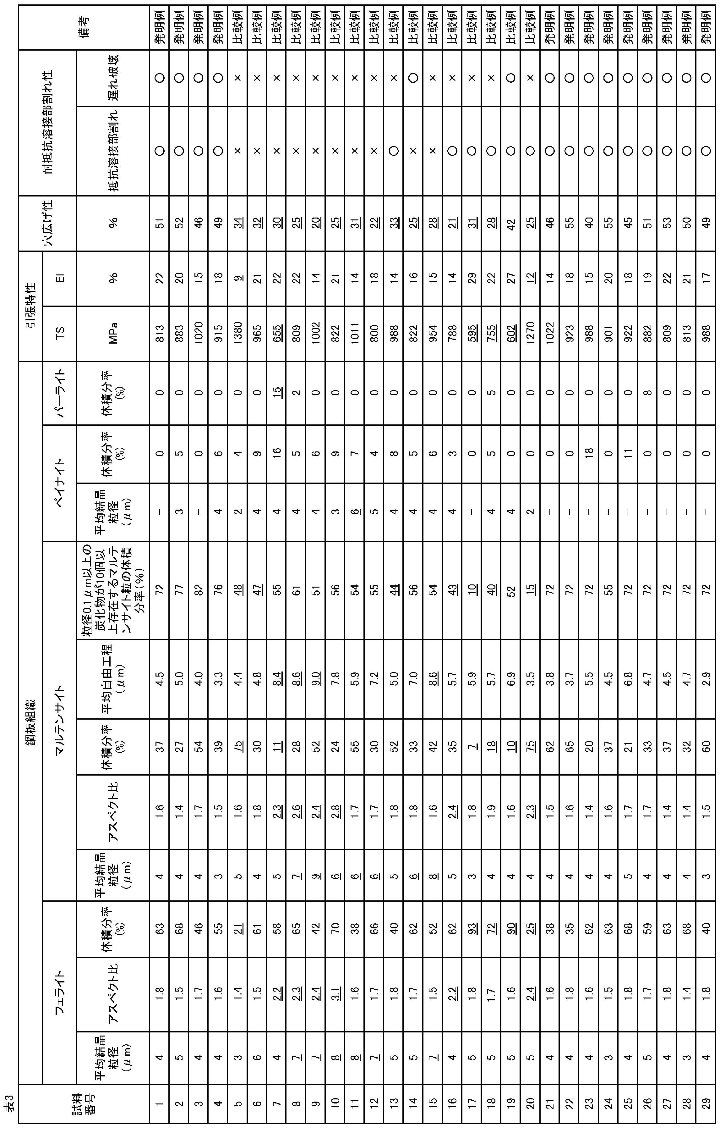
発明例はいずれも、TSが780MPa以上の高強度を有し、かつ加工性(伸びおよび穴広げ性)と耐抵抗溶接部割れ性の両方を兼備する鋼板であることがわかる。
Claims (6)
- 質量%で、
C:0.05%以上0.18%以下、
Si:0.8%以下、
Mn:1.5%以上3.0%以下、
P:0.05%以下、
S:0.005%以下、
Al:0.01%以上0.10%以下、
N:0.010%以下、
Mo:0.05%以上0.50%以下、
Ti:0.01%以上0.10%以下、および
B:0.0002%以上0.0100%以下を含有し、
残部がFeおよび不可避的不純物からなる成分組成を有し、
ここで、Mo、N、TiおよびBが式(1):
[Mo]+2×([Ti]-3.4×[N])+45×[B]≧0.20
(ここで、[Mo]、[Ti]、[N]および[B]は、それぞれ、Mo、Ti、NおよびBの含有量(質量%)であり、[N]は0質量%であってもよい。)を満たし、
体積分率で、
フェライトが30%以上70%以下、
マルテンサイトが20%以上70%以下、
パーライトが10%以下(0%含む)および
ベイナイトが20%以下(0%含む)であり、
ここで、
前記フェライトが、平均結晶粒径6μm以下、かつ平均アスペクト比2.0以下を有し、
前記マルテンサイトが、平均結晶粒径5μm以下、かつ平均アスペクト比2.0以下を有し、
前記ベイナイトが、平均結晶粒径5μm以下を有し、
前記マルテンサイトの平均自由行程が8.0μm以下であり、かつ
前記マルテンサイトのうち、マルテンサイト粒内に、粒径0.1μm以上の炭化物が10個以上存在するマルテンサイト粒が、全マルテンサイトに対する体積分率で50%以上であるミクロ組織を有する、
高強度鋼板。 - 前記成分組成が、質量%で、さらに
V:0.06%以下、および
Nb:0.05%以下からなる群より選択される1種以上を含有する、請求項1に記載の高強度鋼板。 - 前記成分組成が、質量%で、さらに
Cr:0.80%以下、
Cu:0.50%以下、
Ni:0.50%以下、
Sb:0.02%以下、ならびに
CaおよびREMから選択される1種以上:0.0050%以下からなる群より選択される1種以上を含有する、請求項1または2に記載の高強度鋼板。 - 請求項1~3のいずれか一項に記載の成分組成を有する鋼素材を、仕上げ圧延の最終パスの圧下率:12%以上、前記最終パスの直前のパスの圧下率:11%以上、仕上げ圧延終了温度:840℃以上950℃以下の条件で熱間圧延し、
前記熱間圧延後、70℃/s以上の第1次平均冷却速度で、700℃以下の第1冷却停止温度まで第1次冷却をし、
前記第1次冷却後、5℃/s以上50℃/s以下の第2次平均冷却速度で、610℃以下の巻取り開始温度まで第2次冷却をし、
次いで、巻き取る、
熱延鋼板の製造方法。 - 請求項4に記載の製造方法で得られた熱延鋼板を酸洗し、冷間圧延する、冷延フルハード鋼板の製造方法。
- 請求項5に記載の製造方法で得られた冷延フルハード鋼板を、0.5℃/min以上5.0℃/min以下の平均加熱速度で、750℃以上900℃以下の均熱温度まで加熱し、前記温度で1時間以上保持した後、1.0℃/h以上100℃/h以下の平均冷却速度で室温まで冷却する、高強度鋼板の製造方法。
Priority Applications (1)
| Application Number | Priority Date | Filing Date | Title |
|---|---|---|---|
| JP2020526464A JP6950826B2 (ja) | 2019-02-21 | 2020-01-23 | 高強度鋼板、熱延鋼板の製造方法、冷延フルハード鋼板の製造方法および高強度鋼板の製造方法 |
Applications Claiming Priority (2)
| Application Number | Priority Date | Filing Date | Title |
|---|---|---|---|
| JP2019-029808 | 2019-02-21 | ||
| JP2019029808 | 2019-02-21 |
Publications (1)
| Publication Number | Publication Date |
|---|---|
| WO2020170710A1 true WO2020170710A1 (ja) | 2020-08-27 |
Family
ID=72144270
Family Applications (1)
| Application Number | Title | Priority Date | Filing Date |
|---|---|---|---|
| PCT/JP2020/002392 Ceased WO2020170710A1 (ja) | 2019-02-21 | 2020-01-23 | 高強度鋼板、熱延鋼板の製造方法、冷延フルハード鋼板の製造方法および高強度鋼板の製造方法 |
Country Status (2)
| Country | Link |
|---|---|
| JP (1) | JP6950826B2 (ja) |
| WO (1) | WO2020170710A1 (ja) |
Cited By (5)
| Publication number | Priority date | Publication date | Assignee | Title |
|---|---|---|---|---|
| WO2022210396A1 (ja) * | 2021-03-31 | 2022-10-06 | 日本製鉄株式会社 | 鋼板、鋼板の製造方法、および中間鋼板の製造方法 |
| JPWO2022269742A1 (ja) * | 2021-06-22 | 2022-12-29 | ||
| WO2023008516A1 (ja) * | 2021-07-28 | 2023-02-02 | 日本製鉄株式会社 | 鋼板及びその製造方法 |
| CN116209781A (zh) * | 2020-09-30 | 2023-06-02 | 日本制铁株式会社 | 钢板 |
| JP2023541175A (ja) * | 2020-09-22 | 2023-09-28 | ポスコ カンパニー リミテッド | 衝突性能に優れた熱延鋼板及びその製造方法 |
Citations (4)
| Publication number | Priority date | Publication date | Assignee | Title |
|---|---|---|---|---|
| WO2017169941A1 (ja) * | 2016-03-31 | 2017-10-05 | Jfeスチール株式会社 | 薄鋼板およびめっき鋼板、並びに、熱延鋼板の製造方法、冷延フルハード鋼板の製造方法、熱処理板の製造方法、薄鋼板の製造方法およびめっき鋼板の製造方法 |
| WO2017169940A1 (ja) * | 2016-03-31 | 2017-10-05 | Jfeスチール株式会社 | 薄鋼板およびめっき鋼板、並びに、熱延鋼板の製造方法、冷延フルハード鋼板の製造方法、熱処理板の製造方法、薄鋼板の製造方法およびめっき鋼板の製造方法 |
| WO2018030500A1 (ja) * | 2016-08-10 | 2018-02-15 | Jfeスチール株式会社 | 高強度薄鋼板およびその製造方法 |
| WO2018043452A1 (ja) * | 2016-08-30 | 2018-03-08 | Jfeスチール株式会社 | 高強度鋼板およびその製造方法 |
-
2020
- 2020-01-23 WO PCT/JP2020/002392 patent/WO2020170710A1/ja not_active Ceased
- 2020-01-23 JP JP2020526464A patent/JP6950826B2/ja active Active
Patent Citations (4)
| Publication number | Priority date | Publication date | Assignee | Title |
|---|---|---|---|---|
| WO2017169941A1 (ja) * | 2016-03-31 | 2017-10-05 | Jfeスチール株式会社 | 薄鋼板およびめっき鋼板、並びに、熱延鋼板の製造方法、冷延フルハード鋼板の製造方法、熱処理板の製造方法、薄鋼板の製造方法およびめっき鋼板の製造方法 |
| WO2017169940A1 (ja) * | 2016-03-31 | 2017-10-05 | Jfeスチール株式会社 | 薄鋼板およびめっき鋼板、並びに、熱延鋼板の製造方法、冷延フルハード鋼板の製造方法、熱処理板の製造方法、薄鋼板の製造方法およびめっき鋼板の製造方法 |
| WO2018030500A1 (ja) * | 2016-08-10 | 2018-02-15 | Jfeスチール株式会社 | 高強度薄鋼板およびその製造方法 |
| WO2018043452A1 (ja) * | 2016-08-30 | 2018-03-08 | Jfeスチール株式会社 | 高強度鋼板およびその製造方法 |
Cited By (15)
| Publication number | Priority date | Publication date | Assignee | Title |
|---|---|---|---|---|
| JP2023541175A (ja) * | 2020-09-22 | 2023-09-28 | ポスコ カンパニー リミテッド | 衝突性能に優れた熱延鋼板及びその製造方法 |
| US12180556B2 (en) | 2020-09-22 | 2024-12-31 | Posco Co., Ltd | Hot rolled steel sheet having excellent crashworthiness and method for manufacturing same |
| JP7569927B2 (ja) | 2020-09-22 | 2024-10-18 | ポスコ カンパニー リミテッド | 衝突性能に優れた熱延鋼板及びその製造方法 |
| CN116209781A (zh) * | 2020-09-30 | 2023-06-02 | 日本制铁株式会社 | 钢板 |
| WO2022210396A1 (ja) * | 2021-03-31 | 2022-10-06 | 日本製鉄株式会社 | 鋼板、鋼板の製造方法、および中間鋼板の製造方法 |
| EP4296396A4 (en) * | 2021-03-31 | 2024-08-07 | Nippon Steel Corporation | Steel plate, method for producing steel plate, and method for producing intermediate steel plate |
| JPWO2022210396A1 (ja) * | 2021-03-31 | 2022-10-06 | ||
| JP7747986B2 (ja) | 2021-03-31 | 2025-10-02 | 日本製鉄株式会社 | 鋼板および鋼板の製造方法 |
| KR102932191B1 (ko) | 2021-03-31 | 2026-03-04 | 닛폰세이테츠 가부시키가이샤 | 강판, 강판의 제조 방법, 및 중간 강판의 제조 방법 |
| WO2022269742A1 (ja) * | 2021-06-22 | 2022-12-29 | 日本製鉄株式会社 | 熱延鋼板およびその製造方法 |
| JPWO2022269742A1 (ja) * | 2021-06-22 | 2022-12-29 | ||
| JP7688287B2 (ja) | 2021-06-22 | 2025-06-04 | 日本製鉄株式会社 | 熱延鋼板およびその製造方法 |
| KR102936922B1 (ko) | 2021-06-22 | 2026-03-11 | 닛폰세이테츠 가부시키가이샤 | 열연 강판 및 그 제조 방법 |
| WO2023008516A1 (ja) * | 2021-07-28 | 2023-02-02 | 日本製鉄株式会社 | 鋼板及びその製造方法 |
| JPWO2023008516A1 (ja) * | 2021-07-28 | 2023-02-02 |
Also Published As
| Publication number | Publication date |
|---|---|
| JPWO2020170710A1 (ja) | 2021-03-11 |
| JP6950826B2 (ja) | 2021-10-13 |
Similar Documents
| Publication | Publication Date | Title |
|---|---|---|
| US11136643B2 (en) | High-strength steel sheet and method for producing same | |
| JP6501046B1 (ja) | 熱間プレス部材およびその製造方法ならびに熱間プレス用冷延鋼板およびその製造方法 | |
| JP6544494B1 (ja) | 高強度亜鉛めっき鋼板およびその製造方法 | |
| JP7088140B2 (ja) | 高強度薄鋼板およびその製造方法 | |
| JP6394812B2 (ja) | 薄鋼板およびめっき鋼板、並びに、熱延鋼板の製造方法、冷延フルハード鋼板の製造方法、熱処理板の製造方法、薄鋼板の製造方法およびめっき鋼板の製造方法 | |
| JP6296214B1 (ja) | 薄鋼板およびその製造方法 | |
| KR102145293B1 (ko) | 도금 강판 및 그의 제조 방법 | |
| JP6874919B1 (ja) | 高強度薄鋼板およびその製造方法 | |
| JP6308333B2 (ja) | 薄鋼板およびめっき鋼板、並びに、熱延鋼板の製造方法、冷延フルハード鋼板の製造方法、熱処理板の製造方法、薄鋼板の製造方法およびめっき鋼板の製造方法 | |
| US12215405B2 (en) | Hot-pressed member, cold-rolled steel sheet for hot pressing, and manufacturing methods therefor | |
| KR101445465B1 (ko) | 가공성과 스폿 용접성이 우수한 고강도 용융 아연 도금 강판 및 그 제조 방법 | |
| JP6950826B2 (ja) | 高強度鋼板、熱延鋼板の製造方法、冷延フルハード鋼板の製造方法および高強度鋼板の製造方法 | |
| WO2013099712A1 (ja) | 低温靭性と耐食性に優れたプレス加工用溶融めっき高強度鋼板とその製造方法 | |
| WO2019003448A1 (ja) | 熱間プレス部材およびその製造方法ならびに熱間プレス用冷延鋼板 | |
| JPWO2019003539A1 (ja) | 熱間プレス部材およびその製造方法ならびに熱間プレス用冷延鋼板およびその製造方法 | |
| JP7800780B1 (ja) | 高強度鋼板およびその製造方法 | |
| CN116897217A (zh) | 钢板、构件和它们的制造方法 |
Legal Events
| Date | Code | Title | Description |
|---|---|---|---|
| ENP | Entry into the national phase |
Ref document number: 2020526464 Country of ref document: JP Kind code of ref document: A |
|
| 121 | Ep: the epo has been informed by wipo that ep was designated in this application |
Ref document number: 20758547 Country of ref document: EP Kind code of ref document: A1 |
|
| NENP | Non-entry into the national phase |
Ref country code: DE |
|
| 122 | Ep: pct application non-entry in european phase |
Ref document number: 20758547 Country of ref document: EP Kind code of ref document: A1 |