WO2020171024A1 - Stratifié et procédé de production d'un stratifié - Google Patents
Stratifié et procédé de production d'un stratifié Download PDFInfo
- Publication number
- WO2020171024A1 WO2020171024A1 PCT/JP2020/006114 JP2020006114W WO2020171024A1 WO 2020171024 A1 WO2020171024 A1 WO 2020171024A1 JP 2020006114 W JP2020006114 W JP 2020006114W WO 2020171024 A1 WO2020171024 A1 WO 2020171024A1
- Authority
- WO
- WIPO (PCT)
- Prior art keywords
- polymer
- polymer layer
- unit
- layer
- base material
- Prior art date
- Legal status (The legal status is an assumption and is not a legal conclusion. Google has not performed a legal analysis and makes no representation as to the accuracy of the status listed.)
- Ceased
Links
Images

Classifications
-
- H—ELECTRICITY
- H01—ELECTRIC ELEMENTS
- H01B—CABLES; CONDUCTORS; INSULATORS; SELECTION OF MATERIALS FOR THEIR CONDUCTIVE, INSULATING OR DIELECTRIC PROPERTIES
- H01B5/00—Non-insulated conductors or conductive bodies characterised by their form
- H01B5/14—Non-insulated conductors or conductive bodies characterised by their form comprising conductive layers or films on insulating-supports
-
- B—PERFORMING OPERATIONS; TRANSPORTING
- B05—SPRAYING OR ATOMISING IN GENERAL; APPLYING FLUENT MATERIALS TO SURFACES, IN GENERAL
- B05D—PROCESSES FOR APPLYING FLUENT MATERIALS TO SURFACES, IN GENERAL
- B05D1/00—Processes for applying liquids or other fluent materials
- B05D1/36—Successively applying liquids or other fluent materials, e.g. without intermediate treatment
-
- B—PERFORMING OPERATIONS; TRANSPORTING
- B05—SPRAYING OR ATOMISING IN GENERAL; APPLYING FLUENT MATERIALS TO SURFACES, IN GENERAL
- B05D—PROCESSES FOR APPLYING FLUENT MATERIALS TO SURFACES, IN GENERAL
- B05D7/00—Processes, other than flocking, specially adapted for applying liquids or other fluent materials to particular surfaces or for applying particular liquids or other fluent materials
-
- B—PERFORMING OPERATIONS; TRANSPORTING
- B05—SPRAYING OR ATOMISING IN GENERAL; APPLYING FLUENT MATERIALS TO SURFACES, IN GENERAL
- B05D—PROCESSES FOR APPLYING FLUENT MATERIALS TO SURFACES, IN GENERAL
- B05D7/00—Processes, other than flocking, specially adapted for applying liquids or other fluent materials to particular surfaces or for applying particular liquids or other fluent materials
- B05D7/24—Processes, other than flocking, specially adapted for applying liquids or other fluent materials to particular surfaces or for applying particular liquids or other fluent materials for applying particular liquids or other fluent materials
-
- B—PERFORMING OPERATIONS; TRANSPORTING
- B32—LAYERED PRODUCTS
- B32B—LAYERED PRODUCTS, i.e. PRODUCTS BUILT-UP OF STRATA OF FLAT OR NON-FLAT, e.g. CELLULAR OR HONEYCOMB, FORM
- B32B27/00—Layered products comprising a layer of synthetic resin
- B32B27/30—Layered products comprising a layer of synthetic resin comprising vinyl (co)polymers; comprising acrylic (co)polymers
-
- H—ELECTRICITY
- H05—ELECTRIC TECHNIQUES NOT OTHERWISE PROVIDED FOR
- H05K—PRINTED CIRCUITS; CASINGS OR CONSTRUCTIONAL DETAILS OF ELECTRIC APPARATUS; MANUFACTURE OF ASSEMBLAGES OF ELECTRICAL COMPONENTS
- H05K1/00—Printed circuits
- H05K1/02—Details
- H05K1/03—Use of materials for the substrate
Definitions
- the present invention relates to a laminated body in which a polymer layer including a plurality of unit polymer layers containing a tetrafluoroethylene-based polymer is laminated on a long base material layer, and a manufacturing method thereof.
- TFE-based polymer such as polytetrafluoroethylene (PTFE) is excellent in physical properties such as chemical resistance, water/oil repellency, heat resistance, and electrical characteristics. Therefore, when a polymer layer or a film of TFE polymer is laminated on the base material layer, a laminate having the above-mentioned properties can be obtained. Such a laminate is suitably used as a material for a printed wiring board.
- the TFE-based polymer has poor adhesive strength, heat treatment is required when using either the dispersion liquid or the film when forming the polymer layer on the surface of the base material layer. In this case, the high linear expansion coefficient of the TFE polymer causes the warpage of the laminate. Therefore, measures have been taken to limit the thickness of the polymer layer and to combine other layers having different linear expansion coefficients (see Patent Documents 1 and 2).
- the configuration (thickness, layer configuration) of the polymer layer and the usable base material layer are limited, so that there is a limit to the mode.
- a thin base material layer having a large area, in particular, only a thick polymer layer containing TFE polymer as a main component is formed on the surface of a long metal foil, the warpage rate is low, and a laminate in which both are firmly adhered is obtained. Absent.
- the present inventors have found that when using a TFE-based polymer, a polymer layer is formed by laminating a plurality of unit polymer layers, and the conditions (thickness, molding conditions, etc.) of each unit polymer layer are set. It was found that, if set, a laminate having a thick warp and a low warp rate can be obtained.
- a long base material layer is laminated with a polymer layer including a plurality of unit polymer layers containing a tetrafluoroethylene-based polymer, and the absolute value of the linear expansion coefficient of the polymer layer is 50 ppm/° C. or less.
- the polymer layer has a thickness of the unit polymer layer on a side closer to the base material layer larger than a thickness of the unit polymer layer on a side far from the base material layer.
- the laminate according to any one of [1] to [5], which comprises a combination of unit polymer layers.
- the polymer layer has two adjoining unit polymer layers each containing a component different from the tetrafluoroethylene-based polymer, and in the adjoining two unit polymer layers, the one on the side closer to the base material layer.
- a long base material layer is laminated with a polymer layer including a plurality of unit polymer layers containing a tetrafluoroethylene-based polymer, and the absolute value of the linear expansion coefficient of the polymer layer is 50 ppm/° C. or less.
- a method for producing a layered product, each unit polymer layer is formed from a powder dispersion containing the powder of the tetrafluoroethylene-based polymer and a dispersant or a binder and a liquid dispersion medium, Production method.
- the dispersant is a dispersant made of a thermally decomposable fluoropolymer.
- a laminate having a thick polymer layer can be obtained while having a low warpage rate.
- “D50 of powder” is the volume-based cumulative 50% diameter of the powder, the particle size distribution of the powder is measured by the laser diffraction/scattering method, and the cumulative curve is calculated with the total volume of the powder particles as 100%, and the cumulative value. It is the particle size at the point where the cumulative volume becomes 50% on the curve.
- “D90 of powder” is a volume-based cumulative 90% diameter of powder, which is similarly obtained.
- the “melt viscosity of the polymer” is based on ASTM D 1238, and a sample of the polymer (2 g) heated in advance for 5 minutes at the measurement temperature using a flow tester and a die of 2 ⁇ -8L was loaded with 0.7 MPa. It is the value measured by holding at the measurement temperature at.
- the “melting temperature (melting point) of the polymer” is a temperature corresponding to the maximum value of the melting peak of the polymer measured by the differential scanning calorimetry (DSC) method.
- the “viscosity of the powder dispersion” is the viscosity of the powder dispersion measured with an E-type viscometer at a rotor rotation speed of 50 rpm in an environment of 25° C. ⁇ 2° C.
- the “viscosity ratio of the powder dispersion” is the viscosity of the powder dispersion measured with an E-type viscometer while changing the rotor rotation speed in an environment of 25°C ⁇ 2°C. It is a value obtained by dividing by the viscosity when the rotation speed is 50 rpm.
- “Ten-point average roughness (Rzjis)” is a value defined in Annex JA of JIS B 0601:2013.
- "Arithmetic mean roughness (Ra)” is an arithmetic mean roughness measured based on JIS B0601:2013 (ISO4287:1997, Amd.1:2009).
- the reference length lr (cutoff value ⁇ c) for the roughness curve when Ra was determined was 0.8 mm.
- the “warpage ratio of the laminate” is measured by cutting a 180 mm square test piece from the laminate and measuring the test piece according to the measuring method specified in JIS C 6471:1995 (corresponding international standard IEC 249-1:1982). Value.
- the “coefficient of linear expansion of the polymer layer” is the value obtained by preparing a single piece (length 20 cm, width 4 cm) of the polymer layer from the laminate, annealing the single piece at 150° C. for 30 minutes, and then applying nitrogen gas. It is a value (ppm/° C.) obtained from the dimensional change rate of a single piece, which is measured by raising the temperature from 30° C. to 200° C. at 2° C./min while applying a tension of 6 mN in an atmosphere. ..
- FIG. 1 is a sectional view schematically showing an embodiment of a laminated body of the present invention
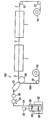
- FIG. 2 is a schematic configuration diagram showing an example of a laminated body manufacturing apparatus used in the present invention.
- the upper side in FIGS. 1 and 2 is referred to as “upper” or “upper”, and the lower side is referred to as “lower” or “lower”.
- the dimensional ratios in FIGS. 1 and 2 are different from the actual ones for convenience of description.
- the laminate 1 shown in FIG. 1 has a long base material layer 2 and a polymer layer 3 laminated on the base material layer 2.
- the polymer layer 3 is located between a plurality of (three in the present embodiment) unit polymer layers 31 containing a tetrafluoroethylene-based polymer (TFE-based polymer) and two adjacent unit polymer layers 31. And a minute space 32.
- TFE-based polymer tetrafluoroethylene-based polymer
- a minute space 32 When distinguishing the three unit polymer layers 31, they are described as a unit polymer layer 311, a unit polymer layer 312, and a unit polymer layer 313 in order from the lower side.
- the two minute spaces 32 they are described as a minute space 321 and a minute space 322 in order from the lower side.
- the interface between the unit polymer layers is distinguished by the component difference between the unit polymer layers and the minute space between the layers, and the case where the unit polymer layers are not highly integrated and are not distinguished. There is.
- the laminated body 1 can be manufactured using, for example, the manufacturing apparatus shown in FIG.
- the manufacturing apparatus 100 illustrated in FIG. 2 includes a roll 10 around which the base material layer 2 is wound, a die coater 12 that applies the powder dispersion liquid 300 to the surface of the base material layer 2 to form a wet film, and a wet film.
- the drying furnace D for removing the liquid dispersion medium to form a dry film, the baking furnace F for baking the dry film to form the unit polymer layer 31, and the base layer 2 on which the unit polymer layer 31 is formed are wound up. And a roll 16.
- the manufacturing apparatus 100 is arranged so as to face the die coater 12 with the guide roll 18 that guides the base material layer 2 unwound from the roll 10 to the die coater 12, and a wet film is formed.
- a guide roll 24 is arranged so as to face the die coater 12 with the guide roll 18 that guides the base material layer 2 unwound from the roll 10 to the die coater 12, and a wet film is formed.
- the die back roll 20 for guiding the base material layer 2 to the drying oven D
- the guide roll 22 for guiding the base material layer 2 having the unit polymer layer 31 formed thereon through the drying furnace D and the firing furnace F to the roll 16.
- a guide roll 24 is arranged so as to face the die coater 12 with the guide roll 18 that guides the base material layer 2 unwo
- the manufacturing apparatus 100 includes a tank 26 that stores the powder dispersion liquid 300, a stirring device 30 that has a stirring blade 28 that stirs the powder dispersion liquid 300 in the tank 26, and ultrasonic waves to the powder dispersion liquid 300 in the tank 26.
- An ultrasonic device 32 for irradiating the liquid a liquid feed line 34 for feeding the powder dispersion liquid 300 in the tank 26 to the die coater 12, a pump 36 provided in the middle of the liquid feed line 34, and a liquid feed line.
- the filter 38 is provided in the middle of 34.
- the base material layer 2 in the present invention is preferably a metal foil. If the metal foil is processed, the laminated body 1 can be suitably used as a printed wiring board.
- the metal forming the metal foil include copper, copper alloy, stainless steel, nickel, nickel alloy (including 42 alloy), aluminum, aluminum alloy, titanium, and titanium alloy.
- a copper foil is preferable, a rolled copper foil having no distinction between front and back or an electrolytic copper foil having distinction between front and back is more preferable, and a rolled copper foil is further preferable. Since the rolled copper foil has a small surface roughness, the transmission loss can be reduced even when the laminated body 1 is processed into a printed wiring board.
- the rolled copper foil is preferably used after being immersed in a hydrocarbon-based organic solvent to remove the rolling oil.
- the ten-point average roughness (Rzjis) of the surface of the base material layer 2 is preferably 0.01 ⁇ m or more, more preferably 0.2 ⁇ m or more, still more preferably 0.7 ⁇ m or more.
- the ten-point average roughness is preferably 4 ⁇ m or less, more preferably 1.5 ⁇ m or less, and further preferably less than 1.0 ⁇ m.
- the adhesiveness with the polymer layer 3 is good, and it is easy to obtain a printed wiring board having excellent transmission characteristics.
- the base material layer 2 may have any thickness as long as it can exert a sufficient function in the intended use of the laminate 1.
- the thickness of the base material layer 2 is preferably less than 20 ⁇ m, more preferably 2 to 15 ⁇ m.
- the surface of the base material layer 2 may be partially or entirely treated with a silane coupling agent.
- the ten-point average roughness of the surface of the base material layer 2 can be appropriately adjusted by etching the surface or forming a roughening treatment layer.
- the powder dispersion liquid 300 in the present invention contains a TFE polymer powder, a dispersant or a binder, and a liquid dispersion medium.
- the D50 of the powder in the present invention is preferably 0.05 to 6 ⁇ m, more preferably 0.2 to 3 ⁇ m. Within this range, the fluidity and dispersibility of the powder will be good, and the electrical properties (low dielectric constant, etc.) and heat resistance of the polymer layer 3 will most likely be exhibited.
- the D90 of the powder is preferably 8 ⁇ m or less, more preferably 5 ⁇ m or less. Within this range, the fluidity and dispersibility of the powder will be good, and the electrical properties (low dielectric constant, etc.) and heat resistance of the polymer layer 3 will most likely be exhibited.
- the powder in the present invention is preferably a powder containing a TFE polymer as a main component.
- the content of the TFE polymer in the powder is preferably 80% by mass or more, more preferably 100% by mass.
- the powder may contain a heat-resistant non-fluorine polymer such as an aromatic polyester, a polyamide-imide, a thermoplastic polyimide, a polyphenylene ether, and a polyphenylene oxide.
- the loosely packed bulk density of the powder is preferably 0.08 to 0.5 g/mL.
- the close packing bulk density of the powder is more preferably 0.1 to 0.8 g/mL.
- the TFE polymer in the present invention is a polymer containing a unit based on tetrafluoroethylene (TFE) (hereinafter, also referred to as “TFE unit”).
- TFE tetrafluoroethylene
- the TFE polymer has a melt viscosity at 380° C. of preferably 1 ⁇ 10 2 to 1 ⁇ 10 8 Pa ⁇ s, more preferably 1 ⁇ 10 3 to 1 ⁇ 10 6 Pa ⁇ s.
- the TFE polymer is a homopolymer (PTFE) composed of TFE units, a copolymer containing TFE units and units based on perfluoro(alkyl vinyl ether) (hereinafter, also referred to as “PAVE units”) (hereinafter, also referred to as “PFA”). ), a copolymer containing a TFE unit and a unit based on hexafluoropropylene (hereinafter, also referred to as “HFP unit”), and a unit based on TFE unit and fluoroalkylethylene (hereinafter, also referred to as “FAE unit”). Copolymers containing are preferred.
- the homopolymer composed of TFE units also includes a polymer containing a very small amount of units other than TFE units (so-called modified PTFE).
- the polymer containing an extremely small amount of other units preferably contains 99.5 mol% or more, and more preferably 99.9 mol% or more of TFE units based on all the units contained in the polymer.
- PTFE includes low molecular weight PTFE.
- the low molecular weight PTFE a polymer obtained by irradiating a high molecular weight PTFE (melt viscosity of about 1 ⁇ 10 9 to 1 ⁇ 10 10 Pa ⁇ s) with radiation (see International Publication No. 2018/026012 etc.), A polymer obtained by using a chain transfer agent when polymerizing TFE (see WO 2010/114033 etc.), having a core-shell structure composed of a core portion and a shell portion, and only the shell portion having the above melt viscosity And the like (see International Publication No. 2016/170918).
- the standard specific gravity (specific gravity measured according to ASTM D4895-04) of low molecular weight PTFE is preferably 2.14 to 2.22, more preferably 2.16 to 2.20.
- the TFE-based polymer also includes a copolymer containing a unit other than the TFE unit.
- the copolymer containing other units preferably contains more than 0.5 mol% of other units with respect to the total units of the polymer.
- a unit having a functional group described later is preferable in addition to the PAVE unit, HFP unit, and FAE unit.
- the TFE polymer preferably has an oxygen-containing polar group. It is considered that the oxygen-containing polar group strongly interacts with the oxides and metal atoms present on the surface of the metal foil which is the base material layer 2, and the polymer layer 3 exhibits high adhesiveness with the base material layer 2.
- the TFE polymer having an oxygen-containing polar group a copolymer having a unit based on a monomer having an oxygen-containing polar group is preferable.
- the oxygen-containing polar group is a polar atomic group containing an oxygen atom.
- the oxygen-containing polar group does not include the ester bond itself and the ether bond itself, but includes an atomic group containing these bonds as a characteristic group.
- the proportion of PAE units is preferably 0.5 to 9.97 mol% with respect to all units constituting the TFE polymer.
- a monomer unit having a cyclic acid anhydride residue is preferable. Two or more types of polar units may be contained in the TFE polymer. Examples of the monomer having a cyclic acid anhydride residue include itaconic acid anhydride, citraconic acid anhydride, 5-norbornene-2,3-dicarboxylic acid anhydride (also known as hymic acid anhydride; hereinafter also referred to as “NAH”) and anhydride. Maleic acid is preferred and NAH is particularly preferred.
- the proportion of the polar unit is preferably 0.01 to 3 mol% with respect to all units constituting the TFE polymer.
- the TFE polymer in this case may further include units other than TFE units, PAE units, and polar units (hereinafter, also referred to as “fourth units”).
- the fourth unit may be two or more types.
- Examples of the monomer forming the fourth unit include ethylene, propylene, vinyl chloride, vinylidene chloride, vinyl fluoride, vinylidene fluoride (VDF), and chlorotrifluoroethylene (CTFE).
- ethylene, VDF and CTFE are preferable, and ethylene is particularly preferable.
- the proportion of the fourth unit in the TFE-based polymer is preferably 0 to 50 mol%, and particularly preferably 0 to 40 mol%, based on all units constituting the TFE-based polymer.
- the melting temperature of the TFE polymer is preferably 140 to 320°C, more preferably 200 to 320°C, particularly preferably 260 to 320°C. In this case, it is easy to further improve the adhesiveness of the polymer layer 3 to the base material layer 2.
- the TFE polymer is preferably PFA containing 2 mol% or more of PAVE units with respect to all units.
- the PFA has a polar functional group including a TFE unit, a PAVE unit and a unit based on a monomer having a polar functional group.
- PFA (1) and PFA (2) having no polar functional group, which contains TFE units and PAVE units and contains 2.0 to 5.0 mol% of PAVE units based on all units, are more preferable.
- PFA (1) contains TFE units in an amount of 90 to 99 mol%, PAVE units in an amount of 1.5 to 9.97 mol%, and units based on a monomer having a polar functional group in an amount of 0.01 to 1. It is preferable to contain 5 mol% of each. Further, itaconic anhydride, citraconic anhydride and NAH are preferable as the monomer having a polar functional group. Specific examples of PFA (1) include the polymers described in WO2018/16644.
- PFA (2) is composed only of TFE units and PAVE units, and may contain 95.0 to 98.0 mol% of TFE units and 2.0 to 5.0 mol% of PAVE units based on all units. preferable.
- the content of PAVE units in PFA (2) is preferably 2.1 mol% or more, and more preferably 2.2 mol% or more, based on all units.
- the PFA (2) having no polar functional group means that the polymer has less than 500 polar functional groups per 10 6 carbon atoms constituting the polymer main chain. means.
- the number of polar functional groups is preferably 100 or less, more preferably less than 50. The lower limit of the number of polar functional groups is usually 0.
- PFA (2) may be produced by using a polymerization initiator, a chain transfer agent, or the like that does not generate a polar functional group as an end group of the polymer main chain, and may have a polar functional group. It may also be produced by fluorinating a PFA or the like having a polar functional group derived from it as an end group of the polymer main chain. Examples of the fluorination treatment method include a method using fluorine gas (see JP-A-2019-194314, etc.).
- the liquid dispersion medium in the present invention is a dispersion medium in which powder is dispersed, is a compound that is liquid at 25° C., and may be an aqueous liquid dispersion medium or a non-aqueous liquid dispersion medium.
- the liquid dispersion medium is preferably water, amide, alcohol, sulfoxide, ester, ketone and glycol ether, more preferably water, ketone and amide, still more preferably ketone and amide.
- the dispersant particularly, an EO polymer described later
- Two or more kinds of liquid dispersion media may be used in combination.
- liquid dispersion medium examples include water, methanol, ethanol, isopropanol, N,N-dimethylformamide, N,N-dimethylacetamide, N-methyl-2-pyrrolidone, dimethyl sulfoxide, diethyl ether, dioxane, ethyl lactate, Examples thereof include ethyl acetate, butyl acetate, methyl ethyl ketone, methyl isopropyl ketone, cyclopentanone, cyclohexanone, ethylene glycol monoisopropyl ether, and cellosolve (methyl cellosolve, ethyl cellosolve, etc.).
- the liquid dispersion medium is preferably a compound that does not instantly volatilize, and specifically, a compound having a boiling point of 80 to 275° C. is more preferable, and a compound having a boiling point of 125 to 250° C. is further preferable. Within this range, when the liquid dispersion medium is distilled off by heating from the powder dispersion liquid 300, volatilization of the liquid dispersion medium and decomposition and flow of the dispersant effectively proceed.
- liquid dispersion medium examples include methyl ethyl ketone, cyclohexane, 2-propanol, 1-propanol, 1-butanol, 1-methoxy-2-propanol, (N-methyl-2-pyrrolidone, ⁇ -butyrolactone, cyclohexanone and cyclopentanone.
- Preferred are methyl ethyl ketone, cyclohexanone and N-methyl-2-pyrrolidone.
- the dispersant in the present invention is preferably a thermally decomposable fluoropolymer, which is different from the TFE polymer, has a thermal decomposition initiation temperature of 50 to 150° C., and has a mass reduction rate at 150° C. of 50% by mass/min or more. Is more preferred. As will be described later, in this range, the component derived from the dispersant is unevenly distributed in the polymer layer, and the warpage rate of the laminate is more easily controlled.
- the thermal decomposition start temperature is a temperature at which the mass reduction of the dispersant starts in the analysis of the dispersant using a thermogravimetric analyzer.
- the mass reduction rate is the mass reduction rate (%) when the dispersant is exposed at 150° C.
- the weight average molecular weight of the thermally decomposable fluoropolymer is preferably 2000 to 80,000, more preferably 6000 to 20,000.
- the heat-decomposable fluoropolymer having such a weight average molecular weight has an excellent function as a dispersant, and at the same time, it is easy to control the amount of components (for example, decomposition products) derived from the heat-decomposable fluoropolymer remaining in the polymer layer 3.
- thermally decomposable fluoropolymer shows an oxyethylene group (hereinafter, also referred to as “EO group”) and a polyfluoroalkyloxycarbonyl group (hereinafter, also referred to as “F group”) from the viewpoint of exhibiting good thermal decomposition behavior. .) are preferred (hereinafter, also referred to as “EO polymer”).
- EO group oxyethylene group
- F group polyfluoroalkyloxycarbonyl group
- the EO group content of the EO polymer is preferably 20 to 50% by mass, more preferably 25 to 40% by mass.
- An EO polymer having an EO group in the above content provides a good balance between the content of EO group and the content of F group, and therefore, it suitably functions as a dispersant in a temperature range where a wet film is a dry film. .. Moreover, when such an EO polymer is used, the amount of the component derived from the EO polymer in the polymer layer 3 can be more easily controlled. Therefore, the polymer layer 3 exhibits high adhesiveness and excellent electrical characteristics, and is easily formed with a low warpage rate.
- n 12 to 200, preferably 20 to 120.
- R H is a hydrogen atom, an alkyl group or a phenyl group, and is preferably a hydrogen atom or a methyl group.
- the side chain containing an EO group having such a structure is preferable because it starts decomposition in a temperature range where the wet film is a dry film. Also, by selecting the number of n and the type of RH , the affinity of the EO polymer for the powder or liquid dispersion medium can be adjusted accordingly.
- Specific examples of the group represented by the above formula include —C(O)O—(CH 2 CH 2 O) 90 —H, —C(O)O—(CH 2 CH 2 O) 120 —H, — C(O)O-(CH 2 CH 2 O) 23 -CH 3 , -C(O)O-(CH 2 CH 2 O) 66 -CH 3 , -C(O)O-(CH 2 CH 2 O ) 90 --CH 3 , --C(O)O--(CH 2 CH 2 O) 120 --CH 3 , --C(O)O--(CH 2 CH 2 O) 30 --(CH 2 ) 12 H, --C (O)O-(CH 2 CH 2 O) 30 -(CH 2 ) 18 H, -C(O)O-(CH 2 CH 2 O) 4 -(CH 2 ) 12 H, -C(O)O -(CH 2 CH 2 O) 6 ⁇ (CH 2 CH(CH 3 )O) 5 -Ph may be mentioned.
- the fluorine content of the EO polymer is preferably 20 to 40% by mass, more preferably 25 to 40% by mass. Since the EO polymer having the above fluorine content has a good balance between the F group content and the EO group content, it suitably functions as a dispersant in the temperature range where the wet film is a dry film. Moreover, when such an EO polymer is used, the amount of the component derived from the EO polymer in the polymer layer 3 can be more easily controlled. Therefore, the polymer layer 3 exhibits high adhesiveness and excellent electrical characteristics, and is easily formed with a low warpage rate.
- the F group is more preferably a group contained in the side chain of the EO polymer and represented by the formula: —C(O)O—Q H —R F.
- Q H is a methylene group (—CH 2 —) or an ethylene group (—CH 2 CH 2 —), and an ethylene group is preferable.
- R F is a polyfluoroalkyl group having 1 to 6 carbon atoms, and is preferably —(CF 2 ) 4 F or —(CF 2 ) 6 F.
- the side chain containing the F group has a small number of carbon atoms in Q H , the influence of electron withdrawing property by the fluorine atom of R F is further increased, and the cleavage of the ester bond is likely to occur. Therefore, it is easier to control the amount of the decomposition product of the EO polymer in the polymer layer 3. Incidentally, by selecting the type of R F, accordingly, it can adjust the affinity of the EO polymer to powder and liquid dispersion medium.
- F group examples include —C(O)OCH 2 (CF 2 ) 6 F, —C(O)OCH 2 (CF 2 ) 4 F, and —C(O)OCH 2 CH 2 (CF 2 ) 6 F, —C(O)OCH 2 CH 2 (CF 2 ) 4 F and the like.
- the amount of the unit EO and the amount of the unit F with respect to all the units contained in the EO polymer are preferably 10 to 40 mol% and 60 to 90 mol% in this order.
- the amount of each unit with respect to all the units contained in the EO polymer is within the above range, the dispersibility of the powder dispersion liquid 300 is further improved, and the amount of the component derived from the EO polymer in the polymer layer 3 can be suitably controlled. Therefore, the polymer layer 3 exhibits various physical properties including adhesiveness and electrical characteristics in a well-balanced manner, and is easily formed with a lower warp rate.
- the EO polymer may be composed of only the unit EO and the unit F, and may further include an additional unit other than the unit EO and the unit F as long as the effects of the present invention are not impaired.
- the binder in the present invention is a different agent from the TFE polymer and the polymer constituting the dispersant, and is preferably polyamideimide or polyimide.
- the powder dispersion liquid contains the binder, the powder powder is prevented from falling off, the uniformity and surface smoothness of the polymer layer 3 are further improved, and the linear expansion property thereof is easily leveled. Furthermore, the dispersion stability and physical properties (viscosity, thixo ratio, etc.) of the powder dispersion are further improved, and the formation of the polymer layer 3 is likely to proceed more densely.
- the binder not only suppresses an increase in the warpage rate of the laminate 1, but also improves the adhesiveness between the base material layer 2 and the polymer layer 3 more easily.
- the 5% weight loss temperature of the binder is preferably 260°C or higher, more preferably 320°C or higher.
- the 5% weight loss temperature of the binder is preferably 600°C or lower.
- the adhesiveness between the base layer 2 and the polymer layer 3 and the two adjacent polymer layers 31 is more likely to be improved.
- the binder is preferably soluble in the liquid dispersion medium of the powder dispersion, and the solubility of the powder dispersion in the liquid dispersion medium at 25° C. (g/100 g of the liquid dispersion medium) is preferably 5 to 30.
- the original physical properties of the TFE-based polymer such as electric properties are directly expressed, and the adhesion is likely to be improved.
- this effect is likely to be improved.
- the polymer forming the binder may be a non-reactive polymer or a reactive polymer.
- the non-reactive polymer means a polymer having no reactive group that causes a reaction under the conditions of use of the powder dispersion.
- a non-reactive polyimide is a polyimide that has already undergone imidization and does not cause further imidization reaction.
- the reactive polymer means a polymer having the above-mentioned reactive group and undergoing a reaction (condensation reaction, addition reaction, etc.) under the conditions of use of the powder dispersion.
- the polymer constituting the binder may be thermoplastic or thermosetting. If the polymer is thermoplastic, the fluidity of the binder resin is enhanced during heating when forming a layer (coating film) from the powder dispersion, a dense and uniform polymer layer is formed, and adhesion is improved. It's easy to do.
- the thermoplastic polymer a non-reactive thermoplastic polymer is preferable.
- the glass transition point of the thermoplastic polymer is preferably 500° C. or lower. The glass transition point is more preferably 200° C. or higher. In this case, in the formation of the polymer layer 3, dense packing is more likely to be promoted.
- thermosetting a reactive thermosetting polymer is preferable.
- binder examples include polyamide imides such as "HPC” series (manufactured by Hitachi Chemical Co., Ltd.), “Neoprim” series (manufactured by Mitsubishi Gas Chemical Co., Inc.), “Spixeria” series (manufactured by Somar), and “Q-PILON”. Series (manufactured by PI Technology Research Institute), "WINGO” series (manufactured by Wingo Technology Co., Ltd.), “Tomade” series (manufactured by T&K TOKA), “KPI-MX” series (manufactured by Kawamura Sangyo Co., Ltd.), "UPIA-AT” Examples include polyimides such as series (manufactured by Ube Industries).
- the proportion of the powder in the powder dispersion liquid 300 in the present invention is preferably 20 to 60% by mass, more preferably 30 to 50% by mass. Within this range, the polymer layer 3 having excellent electric characteristics and heat resistance can be easily formed.
- the proportion of the dispersant in the powder dispersion liquid 300 according to the present invention is preferably 1 to 15% by mass, more preferably 3 to 10% by mass. Within this range, the dispersibility of the powder dispersion liquid 300 is further improved, and the physical properties (electrical characteristics, adhesiveness, etc.) of the polymer layer 3 are more easily improved.
- the proportion of the liquid dispersion medium in the powder dispersion liquid 300 in the present invention is preferably 30 to 70% by mass, more preferably 40 to 60% by mass. Within this range, the coatability of the powder dispersion liquid 300 is excellent, and the layer (coating film) formability is easily improved.
- the powder dispersion liquid 300 in the present invention may contain other materials as long as the effects of the present invention are not impaired.
- Other materials may or may not be dissolved in the powder dispersion liquid 300.
- Such other materials include non-curable resins.
- non-curable resins include non-meltable resins and heat-meltable resins.
- non-meltable resin include a cured product of a curable resin.
- thermofusible resin include thermosetting resins such as thermoplastic polyimide and thermosetting cured products of curable resins.
- thermoplastic resin polyester resin, polyolefin resin, styrene resin, polycarbonate, thermoplastic polyimide, polyarylate, polysulfone, polyarylsulfone, aromatic polyamide, aromatic polyetheramide, polyphenylene sulfide, polyaryl ether ketone, polyamide
- examples thereof include imide, liquid crystalline polyester and polyphenylene ether, and thermoplastic polyimide, liquid crystalline polyester and polyphenylene ether are preferable.
- examples of such other materials include thixotropic agents, antifoaming agents, inorganic fillers, reactive alkoxysilanes, dehydrating agents, plasticizers, weathering agents, antioxidants, heat stabilizers, lubricants, antistatic agents, and additives. Whitening agents, colorants, conductive agents, release agents, surface treatment agents, viscosity modifiers, and flame retardants are also included.
- the viscosity of the powder dispersion 300 in the present invention is preferably 10 to 10000 mPa ⁇ s, more preferably 15 to 1000 mPa ⁇ s, and further preferably 25 to 500 mPa ⁇ s. In this case, not only the dispersibility of the powder dispersion liquid 300 is excellent, but also the coatability and the mixing property with the varnish of different polymers are excellent.
- the thixo ratio ( ⁇ 1 / ⁇ 2 ) of the powder dispersion liquid 300 in the present invention is preferably 0.8 to 1.4. In this case, not only the dispersibility of the powder dispersion liquid 300 is excellent, but also the coatability of the powder dispersion liquid 300 is good, and the homogeneity of the unit polymer layer 31 is easily improved.
- the powder dispersion liquid 300 has a higher mixing property with the varnish of different polymers.
- the viscosity ⁇ 1 of the powder dispersion liquid 300 measured under the condition that the rotation speed is 30 rpm is the viscosity ⁇ of the powder dispersion liquid 300 measured under the condition that the rotation speed is 60 rpm. It is calculated by dividing by 2 .
- the laminated body 1 shown in FIG. 1 is manufactured as follows using the manufacturing apparatus 100 shown in FIG. First, the powder dispersion 300 is applied to the surface of the base material layer 2 unwound from the roll 10 by the die coater 12 and passed through the drying oven D and the firing oven F in order to form the unit polymer layer 311.
- the base material layer 2 is wound around a roll 16.
- the base material layer 2 on which the unit polymer layer 311 is formed is unwound from the roll 16, the unit polymer layer 312 is formed on the surface of the unit polymer layer 311 in the same manner as above, and the base material layer 2 is formed on the roll 10. Roll up.
- the base material layer 2 on which the unit polymer layers 311 and 312 are formed is unwound from the roll 10, the unit polymer layer 313 is formed on the surface of the unit polymer layer 312 in the same manner as described above, and the base material layer 2 is rolled. Roll it up.
- the powder dispersion liquid 300 is preferably dispersed by the stirring device 30 and the ultrasonic device 32 until just before being transferred to the die coater 12. Thereby, the powder contained in the powder dispersion liquid 300 can be sufficiently dispersed and aggregation can be suppressed.
- the temperature in the dispersion treatment is preferably 25 to 75°C, and particularly preferably 35 to 60°C from the viewpoint of promoting the dispersion of the powder.
- the stirring speed in the stirring treatment is preferably 100 to 5000 rpm, more preferably 300 to 1000 rpm. Within this range, it is easy to suppress the alteration (aggregation, filiblization, etc.) of the TFE polymer while uniformly dispersing the powder in the powder dispersion liquid 300.
- the flow form of the powder dispersion liquid 300 in the stirring treatment is preferably an upward flow or a vertical circulation flow from the viewpoint of promoting redispersion of the sedimentary components of the powder dispersion liquid 300.
- the pressure (absolute value) applied to the powder dispersion liquid 300 is more preferably more than 0 MPa and 0.1 MPa or less.
- the shear stress also includes the pressure applied to the powder dispersion liquid 300 when the powder dispersion liquid 300 is passed through the filter 38 in order to remove foreign substances during liquid transfer.
- the pore size of the filter 38 is preferably 50 to 250 ⁇ m.
- the fed powder dispersion 300 is discharged from the die coater 12 and applied to the surface of the substrate layer 2 or the unit polymer layer 31 to be conveyed, so that a wet film (liquid film) is formed. If the powder dispersion liquid 300 is applied while transporting the long base material layer 2 by roll-to-roll as in the present embodiment, the productivity of the laminate 1 is increased.
- the method, the bar coat method, the fountain Mayer bar method, and the slot die coat method can also be used.
- drying temperature volatilization temperature of the liquid dispersion medium
- the drying temperature means the temperature of the atmosphere in the drying furnace D. At this time, it is preferable to volatilize 50% by mass or more of the liquid dispersion medium contained in the powder dispersion liquid 300.
- the drying may be performed in two or more steps at different temperatures. Drying may be performed under either normal pressure or reduced pressure.
- the dry atmosphere may be an oxidizing gas atmosphere (oxygen gas or the like), a reducing gas atmosphere (hydrogen gas or the like), or an inert gas atmosphere (helium gas, neon gas, argon gas, nitrogen gas or the like).
- the drying temperature is preferably 50 to 280°C, more preferably 120 to 260°C.
- the drying time is preferably 0.1 to 30 minutes, more preferably 0.5 to 20 minutes. If the wet film is dried under the above conditions, the laminate 1 can be preferably manufactured while maintaining high productivity.
- the drying oven D an oven, a ventilation drying oven, or a device that radiates heat rays such as infrared rays is used.
- the TFE polymer is fired at a firing temperature higher than the drying temperature to form the unit polymer layer 31. Since the dry film after the liquid dispersion medium is removed from the wet film is baked, the TFE-based polymer is fused in the state where the powder is tightly packed, so that a uniform unit polymer layer 31 is formed. If the powder dispersion liquid 300 contains a heat-melting resin, the unit polymer layer 31 made of a mixture of a TFE polymer and a heat-soluble resin is formed. A unit polymer layer 31 composed of a base polymer and a cured product of a thermosetting resin is formed.
- the firing temperature is preferably 300° C. or higher, more preferably 330 to 380° C., further preferably 350 to 370° C. Within this range, it is easy to balance the fusion of the TFE polymer and the suppression of the generation of hydrofluoric acid due to the decomposition of the TFE polymer.
- the firing temperature means the temperature of the atmosphere in the firing furnace D.
- the firing time is preferably 30 seconds to 30 minutes, more preferably 1 minute to 1 minute 30 seconds. Within this range, it is easy to balance the fusion of the TFE polymer and the productivity of the laminate 1. Further, the firing may be performed under either normal pressure or reduced pressure.
- the firing atmosphere may be an oxidizing gas atmosphere (oxygen gas or the like), a reducing gas atmosphere (hydrogen gas or the like), or an inert gas atmosphere (helium gas, neon gas, argon gas, nitrogen gas or the like).
- a firing atmosphere a reducing gas atmosphere and an inert gas atmosphere are preferable from the viewpoint of suppressing oxidative deterioration of each of the base material layer 2 and the unit polymer layer 31 to be formed.
- the oxygen gas concentration in the inert gas atmosphere is controlled to be low, and the concentration is preferably 100 to 500 ppm, more preferably 200 to 300 ppm.
- the reducing gas atmosphere is preferably a mixed gas composed of an inert gas and a reducing gas, the oxygen gas concentration of which is suppressed to be low, and nitrogen gas and hydrogen gas of 0.1% by volume or more and less than 4% by volume. Is more preferable, and a mixed gas having an oxygen gas concentration suppressed to 100 to 500 ppm is more preferable.
- the oxygen gas concentration in the mixed gas is more preferably 200 to 300 ppm.
- the firing furnace F an oven, a ventilation drying furnace, a device for radiating heat rays such as infrared rays, or the like is used.
- the firing furnace F is preferably a device that irradiates far infrared rays (far infrared furnace) because it can be fired in a short time and is relatively compact.
- the heat source of the firing furnace F may be a combination of an infrared irradiation source and a hot air supply source.
- the effective wavelength band of far infrared rays is preferably 2 to 20 ⁇ m, more preferably 3 to 7 ⁇ m from the viewpoint of promoting uniform fusion of the TFE polymer.
- the drying furnace D and the baking furnace F it is preferable to arrange a heat source above the furnace so as to directly heat the wet film and the dry film. With this arrangement, it is possible to prevent preferential heat conduction from occurring in the base material layer 2. As a result, the wet film and the dry film are likely to be uniformly heated, and the unit polymer layer 31 to be obtained is less likely to be defective in firing.
- the polymer layer 3 is formed and the laminate 1 is obtained.
- the absolute value of the linear expansion coefficient of the polymer layer of the laminate 1 is 50 ppm/°C or less, preferably 30 ppm/°C or less, and more preferably 25 ppm/°C or less.
- the absolute value of the linear expansion coefficient of the polymer layer of the laminate 1 is preferably 0.1 ppm/°C or higher, more preferably 1 ppm/°C or higher.
- the laminate 1 having the polymer layer having such a linear expansion coefficient can further suppress the warp, and thus a printed wiring board having excellent characteristics can be manufactured.
- Such a laminated body 1 can be obtained by appropriately setting the conditions of each unit polymer layer 31.
- Each unit polymer layer 31 preferably contains a TFE polymer as a main component.
- the content of the TFE polymer in each unit polymer layer 31 is preferably 80% by mass or more, and more preferably 90% by mass.
- the upper limit is 100% by mass. Due to the structure in which a plurality of the respective unit polymer layers 31 are laminated, it is possible to obtain a warp-resistant laminate in which only the polymer layer 3 containing a TFE polymer as a main component is formed on a large-area thin base material layer.
- each unit polymer layer 31 is preferably 10 ⁇ m or less, more preferably 8 ⁇ m or less, still more preferably 5 ⁇ m or less.
- the lower limit of the thickness of each unit polymer layer 31 is usually 0.5 ⁇ m.
- the thickness of the unit polymer layer is 10 ⁇ m or less
- physical properties such as chemical resistance of the laminate are more likely to be improved.
- a laminate having the same polymer layer 3 thickness and each unit polymer layer 31 having a thickness of 10 ⁇ m or less is excellent in etching resistance. Specifically, the expansion of the polymer layer 3 when the base material (copper foil or the like) of the laminate is removed with an etching solution is easily suppressed.
- each unit polymer layer 31 is formed by the progress of fusion of the TFE-based polymer in a state where the powder is densely packed. Therefore, each unit polymer layer 31 is considered to be in a tight state.
- a minute space 32 located between two unit polymer layers 31 is likely to be formed. Conceivable. It is considered that the minute space 32 contains an atmospheric gas when the powder dispersion liquid 300 is applied and a gaseous decomposition product of the dispersant.
- the minute space 32 Due to the presence of the minute space 32, the difference in stress between the two adjacent unit polymer layers 31 caused by the expansion and contraction of the TFE polymer is alleviated, and the effect of reducing the linear expansion coefficient of the polymer layer 3 as a whole is further improved. It is thought that it became remarkable. That is, the minute space 32 functions as a buffer that relieves the difference in stress generated between two adjacent unit polymer layers 31. Therefore, it is preferable that such a minute space 32 exists between the unit polymer layers.
- each unit polymer layer 31 may be the same or different.
- the thickness of the unit polymer layer on the side closer to the substrate is preferably larger than the thickness of the unit polymer layer on the side far from the substrate.
- the polymer layer 31 is composed of three or more unit polymer layers, in two adjacent unit polymer layers, the thickness of the unit polymer layer on the side closer to the base material layer is smaller than that of the unit polymer layer on the side far from the base material layer.
- Polymer layers that include a combination of unit polymer layers that are greater than their thickness are preferred.
- the polymer layer including the above-mentioned combination of unit polymer layers may further include a combination in which two adjacent unit polymer layers have the same thickness. Specifically, in the polymer layer 3 shown in FIG.
- the thickness of the unit polymer layer 31 on the lower side is the upper side (base material layer). It is larger than the thickness of the unit polymer layer 31 on the side farther from 2.
- the unit polymer layer 311, the unit polymer layer 312, and the unit polymer layer 313 have a decreasing thickness in this order.
- the warp rate of the unit polymer layer 31 decreases as the distance from the base material layer 2 increases, so that the linear expansion coefficient of the polymer layer 3 as a whole can be suppressed to a lower value.
- the thickness of the polymer layer 3 is preferably larger than the thickness of the base material layer 2. According to the manufacturing method of the present invention, the laminate 1 having the thick polymer layer 3 can be easily obtained.
- the specific thickness of the polymer layer 3 is preferably 20 ⁇ m or more, more preferably 25 ⁇ m or more, still more preferably 30 ⁇ m or more.
- the upper limit of the thickness of the polymer layer 3 is usually 100 ⁇ m.
- the polymer layer 3 preferably contains a component different from the TFE polymer.
- the distribution density of the component contained in the unit polymer layer on the side closer to the substrate is preferably lower than the distribution density of the component contained in the unit polymer layer on the side far from the substrate. ..
- the unit polymer layer on the side closer to the substrate may not contain the above components.
- the polymer layer 3 is composed of three or more unit polymer layers, in two adjacent unit polymer layers, the distribution density of the above components contained in the unit polymer layer on the side closer to the base material layer is far from the base material layer.
- the polymer layer containing the above-mentioned combination of unit polymer layers may further contain a combination in which the distribution density of the above-mentioned components contained in two adjacent unit-polymer layers is equal or a combination in which none of the unit polymer layers contains the above-mentioned component. Good.
- the upper unit polymer layer 31 in two adjacent unit polymer layers 31, contains a component different from that of the TFE polymer layer. It is preferable.
- the above-mentioned components are contained in each unit polymer layer 31, and among the two adjacent unit polymer layers, the unit polymer layer 31 on the side closer to the base material layer
- the distribution density of the above-mentioned components contained in the unit is lower than the distribution density of the above-mentioned components contained in the unit polymer layer 31 on the side far from the substrate.
- the aspect which contains an inorganic filler as a different component is mentioned.
- the inorganic fillers include boron nitride fillers, beryllia fillers, silica fillers, wollastonite fillers, talc fillers, cerium oxide fillers, aluminum oxide fillers, magnesium oxide fillers, zinc oxide fillers and titanium oxide fillers.
- the inorganic fillers contained in each unit polymer layer may be the same inorganic filler or different inorganic fillers.
- the shape and content of the inorganic filler contained in each unit polymer layer may be the same or different. For example, when the polymer layer 3 of the laminate 1 shown in FIG.
- the shape of the silica filler contained in the unit polymer layer 311, the unit polymer layer 312, and the unit polymer 313, which are unit polymer layers, may be scaly, spherical, or fibrous in this order, and may be fibrous or scaly.
- Shape may be spherical, spherical, scaly, may be fibrous, scaly, spherical, may be scaly, spherical, scaly, may be spherical, fibrous, It may be spherical or fibrous, or spherical, fibrous or spherical. In these preferred embodiments, it is easier to adjust various physical properties such as the linear expansion coefficient of the polymer layer of the laminate 1 based on the physical properties of the components.
- Components different from suitable TFE-based polymers include components derived from dispersants.
- the above components are preferably the dispersant itself or a decomposed product (decomposition residue) of the dispersant.
- Components different from the suitable TFE-based polymer include components derived from a binder.
- the above components are preferably the binder itself or a reaction product of the binder (such as a cured product of a curable polymer when the binder is composed of a curable polymer).
- the component different from the TFE-based polymer may be included in the polymer layer 3 as particles, or may be included in the polymer layer 3 by being compatible with the TFE-based polymer. In the former case, it is preferably contained as particles in a layer having a TFE polymer as a matrix.
- each unit polymer layer 31 uses a TFE-based polymer as a matrix 31a, and particles 31b of a component different from the TFE-based polymer are dispersed in this matrix 31a.
- the particles 31b are particles having a component different from that of the TFE polymer, and may be particles of a dispersant (fluoropolymer) or a decomposed product thereof, or particles of a thermoplastic resin separately added to the powder dispersion liquid 300. .. Since the linear expansion coefficient of the particles 31b is higher than the linear expansion coefficient of the TFE-based polymer, if the unit polymer layer 31 includes the particles 31b, the linear expansion coefficient can be further reduced. In addition, as shown in FIG.
- the amount of particles 31b contained in the unit polymer layer 31 on the lower side is higher (the base material layer). It is smaller than the amount of particles 31b contained in the unit polymer layer 31 on the side farther from 2.
- the amount of particles 31b contained in the unit polymer layer 31 increases in the order of the unit polymer layer 311, the unit polymer layer 312, and the unit polymer layer 313.
- the linear expansion coefficient of the unit polymer layer 31 decreases as the distance from the base material layer 2 increases, so that the linear expansion coefficient of the polymer layer 3 as a whole can be suppressed to a lower value.
- the above-mentioned configuration can be formed when the unit polymer layers 31 are laminated. That is, when the polymer layer 3 is formed, the lower unit polymer layer 311 receives a thermal history due to three times of drying and firing, and the intermediate unit polymer layer 312 receives a thermal history due to two times of drying and firing. On the other hand, the upper unit polymer layer 313 receives a thermal history due to one drying/baking. Due to this difference in thermal history, the degree of decomposition of the dispersant varies in the unit polymer layers 311 to 313. This is considered to be a factor in forming the above configuration.
- the unit polymer layers 31 can be easily obtained by stacking the unit polymer layers 31 as in the present invention.
- the thickness (volume) of the minute space 321 is different from the thickness of the minute space 322 due to the difference in the amount of the gaseous decomposition products of the dispersant. It tends to be larger than (volume).
- the particles 31b are particles of a thermoplastic resin, the above configuration can be easily formed by adjusting the amount of the thermoplastic resin contained in the powder dispersion liquid 300 used for each unit polymer layer 31.
- the rotation direction of the roll 16 that winds up the base material layer 2 on which the unit polymer layer 311 is formed is clockwise, whereas the unit polymer layer 312 is formed.
- the rotation direction of the roll 10 that winds the base material layer 2 is counterclockwise.
- the rotation direction of the roll 16 that winds up the base material layer 2 formed up to the unit polymer layer 313 is clockwise.
- the rotation direction of the roll that winds the base material layer 2 is reversed. Therefore, every time the unit polymer layer 31 is formed, the direction of the tensile force applied to the unit polymer layer 31 is reversed. It is considered that this also contributes to the effect of reducing the warpage rate of the laminate 1.
- the surface of the polymer layer 3 may be surface-treated in order to reduce the linear expansion coefficient of the polymer layer 3 or adjust the adhesiveness of the polymer layer 3.
- this surface treatment include annealing treatment, corona discharge treatment, atmospheric pressure plasma treatment, vacuum plasma treatment, UV ozone treatment, excimer treatment, chemical etching, silane coupling treatment, and fine surface roughening treatment.
- the temperature, pressure, and time in the annealing treatment are preferably 120 to 180° C., 0.005 to 0.015 MPa, and 30 to 120 minutes in this order.
- Examples of the plasma irradiation device in the plasma treatment include a high frequency induction system, a capacitive coupling type electrode system, a corona discharge electrode-plasma jet system, a parallel plate type, a remote plasma type, an atmospheric pressure plasma type and an ICP type high density plasma type.
- Examples of the gas used in the plasma treatment include oxygen gas, nitrogen gas, rare gas (argon or the like), hydrogen gas, ammonia gas and the like, and rare gas and nitrogen gas are preferable.
- Specific examples of the gas used for the plasma treatment include argon gas, a mixed gas of hydrogen gas and nitrogen gas, and a mixed gas of hydrogen gas, nitrogen gas, and argon gas.
- the atmosphere in the plasma treatment is preferably an atmosphere in which the volume fraction of rare gas or nitrogen gas is 70% by volume or more, and more preferably an atmosphere in which the volume fraction of these gases is 100% by volume.
- the arithmetic average roughness (Ra) of the surface of the polymer layer 3 is adjusted to 2.0 ⁇ m or less, and it is easy to form fine irregularities on the surface of the polymer layer 3.
- the layer structure of the multilayer laminate is as follows: substrate/polymer layer 3/base material layer 2, metal foil/polymer layer 3/base material layer 2, metal foil/polymer layer 3/base material layer 2/polymer layer 3/metal Foil can be mentioned.
- Metal foil/polymer layer 3/base material layer 2 indicates a layer structure in which a metal foil, a polymer layer 3 and a base material layer 2 are arranged in this order, and the same applies to other layer structures.
- a multilayer laminate having a layer structure of metal foil/polymer layer 3/base material layer 2 can be produced by laminating a metal foil on the surface of the polymer layer 3 of the laminate 1 of the present invention.
- the substrate examples include a heat resistant resin film, a fiber reinforced resin plate, a laminated plate having a heat resistant resin film layer, and a laminated plate having a fiber reinforced resin layer.
- a heat resistant resin film is preferable as the substrate.
- the heat-resistant resin means a polymer compound having a melting temperature of 280° C. or higher, or a polymer compound having a maximum continuous use temperature of 121° C. or higher specified by JIS C 4003:2010 (IEC 60085:2007). ..
- the heat resistant resin film is a film containing at least one kind of heat resistant resin, and may be a single layer film or a multilayer film.
- polyimide aromatic polyimide etc.
- polyarylate polysulfone
- polyaryl sulfone polyether sulfone etc.
- aromatic polyamide aromatic polyetheramide
- polyphenylene sulfide polyaryl ether ketone
- polyamide imide Liquid crystal polyester
- the thickness of the heat-resistant resin film is preferably 0.5 to 100 ⁇ m, more preferably 3 to 25 ⁇ m from the viewpoints of thinning the printed wiring board and mechanical strength.
- the prepreg is a sheet-shaped substrate in which a base material (tow, woven fabric, etc.) of reinforcing fibers (glass fiber, carbon fiber, etc.) is impregnated with a thermosetting resin or a thermoplastic resin.
- the stacking method include a method of hot pressing the stack 1 of the present invention and the substrate.
- the pressing temperature is preferably equal to or lower than the melting temperature of the TFE polymer, particularly preferably 160 to 220°C. Within this range, the polymer layer 3 and the prepreg can be firmly adhered while suppressing thermal deterioration of the prepreg.
- the pressing temperature is preferably 310 to 400°C. Within this range, the polymer layer 3 and the heat-resistant resin film can be firmly bonded while suppressing the heat deterioration of the heat-resistant resin film.
- the hot pressing is preferably performed in a reduced pressure atmosphere, and particularly preferably performed at a vacuum degree of 20 kPa or less. Within this range, it is possible to prevent air bubbles from being mixed into the interface between the polymer layer 3 and the substrate or the metal foil, and suppress deterioration of the multilayer laminate due to oxidation. Further, during hot pressing, it is preferable to raise the temperature after reaching the above vacuum degree. By doing so, the polymer layer 3 is pressure-bonded in a state before being softened, that is, in a state before a certain degree of fluidity and adhesiveness are developed, so that generation of bubbles can be prevented.
- the pressure in the hot press is preferably 0.2 MPa or more.
- the upper limit of the pressure is preferably 10 MPa or less. Within this range, the polymer layer 3 and the substrate can be firmly adhered while suppressing damage to the substrate.
- the multilayer laminate produced by using the laminate 1 of the present invention can be used for manufacturing a printed wiring board as a flexible copper-clad laminate or a rigid copper-clad laminate.
- SAP method electroplating method
- a printed wiring board can be manufactured by using a method of processing a conductor circuit by an additive method (MSAP method) or the like.
- an interlayer insulating film may be formed on the conductor circuit, and a conductor circuit may be further formed on the interlayer insulating film. Further, a solder resist or a coverlay film may be laminated on the conductor circuit.
- the interlayer insulating film, the solder resist, and the coverlay film can be formed by the powder dispersion liquid 300, for example.
- the present invention is not limited to the configurations of the above-described embodiments.
- the laminate of the present invention may have any other configuration added to the configuration of the above-described embodiment, or may be replaced with any configuration exhibiting the same function.
- other arbitrary steps may be added to the configuration of the above-described embodiment, or may be replaced with an arbitrary step exhibiting the same function.
- the number of unit polymer layers 31 is not limited to three, and may be two or four or more.
- at least one of the minute spaces 321 and 322 may be omitted.
- the unit polymer layer 312 may be formed under reduced pressure.
- the powder dispersion liquid 300 may be applied while the base material layer 2 is not conveyed by roll-to-roll and fixed on the base.
- TFE polymer a copolymer containing 97.9 mol%, 0.1 mol% and 2.0 mol% of units based on TFE, units based on NAH and units based on PPVE in this order (melting temperature: 300° C., 380 Melt viscosity at °C: 3 ⁇ 10 5 Pa ⁇ s)
- TFE-based polymer 2 a copolymer containing 98.7 mol% and 1.3 mol% of TFE units and PPVE units in this order (melting temperature 305° C., 380° C. melt viscosity: 3 ⁇ 10 5 Pa ⁇ s)
- Powder 1 Powder of TFE polymer 1 having D50 of 2.6 ⁇ m and D90 of 7.1 ⁇ m
- Powder 2 Powder of TFE polymer 2 having D50 of 2.3 ⁇ m and D90 of 6.9 ⁇ m D50 and D90 were measured by dispersing the powder in water using a laser diffraction/scattering type particle size distribution measuring device (LA-920 measuring device manufactured by Horiba Ltd.).
- dispersion 1 After 47 parts by mass of N-methyl-2-pyrrolidone (NMP), 2.5 parts by mass of fluoropolymer 1 and 50 parts by mass of powder 1 were put into a pot, zirconia balls were put into the pot. Then, the pot was rolled at 150 rpm for 1 hour to disperse the powder 1 in NMP to prepare a dispersion 1.
- Dispersion liquid 2 Put 46.5 parts by mass of N-methyl-2-pyrrolidone (NMP), 2.5 parts by mass of fluoropolymer 1, 0.5 parts by mass of polyimide 1 and 50 parts by mass of powder 1 into a pot. After that, zirconia balls were put into the pot.
- Dispersion 3 was prepared in the same manner as Dispersion 1 except that Powder 2 was used instead of Powder 1.
- Example 1 Manufacturing evaluation example of laminated body (No. 1) [Example 1-1] First, the dispersion liquid 1 was applied to the surface of a long copper foil (thickness 18 ⁇ m) using a bar coater to form a wet film. Next, the copper foil on which the wet film was formed was passed through a drying oven at 120° C. for 5 minutes and dried by heating to obtain a dry film. Then, the dry film was heated at 380° C. for 3 minutes in a nitrogen oven. As a result, the first unit polymer layer (thickness 5 ⁇ m) was formed on the surface of the copper foil. The heat sources in the drying furnace and the firing furnace were arranged above the furnace so that the wet film and the dry film were directly heated.
- Example 1-2 In Example 1-1, the thickness of the unit polymer layers of the first and second layers was 8 ⁇ m, the thickness of the unit polymer layers of the third and fourth layers was 4 ⁇ m, and the unit of the fifth and sixth layers A laminate 12 was produced in the same manner as in Example 1-1, except that the thickness of the polymer layer was 3 ⁇ m.
- Example 1-3 A laminate 13 was produced in the same manner as in Example 1-1, except that Dispersion Liquid 2 was used instead of Dispersion Liquid 1 in the formation of the first unit polymer layer in Example 1-1.
- Example 1-4 A laminate 14 was produced in the same manner as in Example 1-1, except that Dispersion Liquid 3 was used instead of Dispersion Liquid 1 in Example 1-1.
- Example 1-5 Comparative Example
- a laminate 15 was produced in the same manner as in Example 1-1, except that the polymer layer (thickness 30 ⁇ m) was formed by one operation.
- Example 2 Manufacturing evaluation example of laminated body (Part 2) [Example 2-1] A polymer layer consisting of three unit polymer layers (total thickness 24 ⁇ m) was prepared in the same manner as in Example 1-1, except that the thickness of the unit polymer layer was 8 ⁇ m and the operation of forming the unit polymer layer was 3 times. A laminated body 21 having the above was manufactured. [Example 2-2] A polymer layer consisting of two unit polymer layers (total thickness 24 ⁇ m) was prepared in the same manner as in Example 1-1, except that the thickness of the unit polymer layer was 12 ⁇ m and the operation of forming the unit polymer layer was performed twice. A laminate 22 having the above was manufactured.
- the absolute value of the linear expansion coefficient of each laminate was 25 ppm/° C. or less.
- the copper foil of each laminate was removed by etching treatment with an acidic aqueous solution, and the thickness of the polymer layer after the etching treatment was measured.
- the thickness of the polymer film, which is the laminate 21 after the etching treatment, was 26 ⁇ m, and that of the laminate 22 was 30 ⁇ m.
- the laminate of the present invention has excellent electrical properties and adhesiveness, and has a polymer layer firmly fixed to a base material layer, so that it is used as an antenna component, a printed wiring board, a power semiconductor insulating layer, an aircraft component, an automobile component. It can be used after processing.
- Japanese patent application 2019-029014 filed on Feb. 21, 2019, Japanese patent application 2019-075502 filed on Apr. 11, 2019 and Japanese patent application filed on Aug. 06, 2019.
- the entire contents of the specification, claims, abstract and drawings of the application No. 2019-144667 are incorporated herein by reference and are incorporated as the disclosure of the specification of the present invention.
Landscapes
- Engineering & Computer Science (AREA)
- Life Sciences & Earth Sciences (AREA)
- Wood Science & Technology (AREA)
- Microelectronics & Electronic Packaging (AREA)
- Laminated Bodies (AREA)
- Application Of Or Painting With Fluid Materials (AREA)
Abstract
L'invention concerne : un stratifié présentant un faible taux de gauchissement tout en ayant une couche épaisse de polymère à base de TFE ; et une méthode pour le produire. Ce stratifié 1 est obtenu en stratifiant, sur une longue couche de substrat 2, une couche de polymère 3 comprenant une pluralité de couches de polymère unitaire 31 contenant un polymère à base de tétrafluoroéthylène, la couche de polymère 3 ayant une valeur absolue d'un coefficient de dilatation linéaire d'au plus 50 ppm/°C. En outre, dans le stratifié 1, chaque couche de polymère unitaire 31 est formée à partir d'une dispersion liquide en poudre contenant : une poudre de polymère à base de tétrafluoroéthylène ; un dispersant ou un liant ; et un milieu de dispersion liquide.
Priority Applications (3)
| Application Number | Priority Date | Filing Date | Title |
|---|---|---|---|
| JP2021501990A JPWO2020171024A1 (ja) | 2019-02-21 | 2020-02-17 | 積層体及び積層体の製造方法 |
| CN202080015896.4A CN113508036B (zh) | 2019-02-21 | 2020-02-17 | 层叠体和层叠体的制造方法 |
| KR1020217014149A KR102787276B1 (ko) | 2019-02-21 | 2020-02-17 | 적층체 및 적층체의 제조 방법 |
Applications Claiming Priority (6)
| Application Number | Priority Date | Filing Date | Title |
|---|---|---|---|
| JP2019029014 | 2019-02-21 | ||
| JP2019-029014 | 2019-02-21 | ||
| JP2019075502 | 2019-04-11 | ||
| JP2019-075502 | 2019-04-11 | ||
| JP2019144667 | 2019-08-06 | ||
| JP2019-144667 | 2019-08-06 |
Publications (1)
| Publication Number | Publication Date |
|---|---|
| WO2020171024A1 true WO2020171024A1 (fr) | 2020-08-27 |
Family
ID=72144915
Family Applications (1)
| Application Number | Title | Priority Date | Filing Date |
|---|---|---|---|
| PCT/JP2020/006114 Ceased WO2020171024A1 (fr) | 2019-02-21 | 2020-02-17 | Stratifié et procédé de production d'un stratifié |
Country Status (5)
| Country | Link |
|---|---|
| JP (1) | JPWO2020171024A1 (fr) |
| KR (1) | KR102787276B1 (fr) |
| CN (1) | CN113508036B (fr) |
| TW (1) | TWI841684B (fr) |
| WO (1) | WO2020171024A1 (fr) |
Cited By (1)
| Publication number | Priority date | Publication date | Assignee | Title |
|---|---|---|---|---|
| JP2023155181A (ja) * | 2022-04-07 | 2023-10-20 | ダイキン工業株式会社 | 固体組成物、回路基板、及び、固体組成物の製造方法 |
Citations (3)
| Publication number | Priority date | Publication date | Assignee | Title |
|---|---|---|---|---|
| WO2010084867A1 (fr) * | 2009-01-20 | 2010-07-29 | 東洋紡績株式会社 | Film de résine fluorée multicouche et carte de circuits imprimés |
| JP2011011456A (ja) * | 2009-07-02 | 2011-01-20 | Toyobo Co Ltd | 多層フッ素樹脂フィルムおよび多層フッ素樹脂基板 |
| WO2019031071A1 (fr) * | 2017-08-08 | 2019-02-14 | 住友電気工業株式会社 | Matériau de base de carte de circuits imprimés haute fréquence |
Family Cites Families (9)
| Publication number | Priority date | Publication date | Assignee | Title |
|---|---|---|---|---|
| JPH03130146A (ja) * | 1989-10-16 | 1991-06-03 | Matsushita Electric Works Ltd | 積層板の製造方法 |
| JP4598408B2 (ja) * | 2004-01-15 | 2010-12-15 | ジャパンゴアテックス株式会社 | 接着シート |
| US20100129580A1 (en) * | 2007-04-27 | 2010-05-27 | I.S.T. Corporation | Method for the manufacture of a cylindrical laminated body, and laminated body |
| JP5476821B2 (ja) | 2009-07-02 | 2014-04-23 | 東洋紡株式会社 | 多層フッ素樹脂基板 |
| KR20140144177A (ko) * | 2012-03-14 | 2014-12-18 | 스미토모 베이클리트 컴퍼니 리미티드 | 금속장 적층판, 프린트 배선 기판, 반도체 패키지 및 반도체 장치 |
| JP2016046433A (ja) | 2014-08-25 | 2016-04-04 | 住友電工ファインポリマー株式会社 | プリント配線板及びプリント配線板用基板 |
| JP6674136B2 (ja) * | 2016-04-21 | 2020-04-01 | Dic株式会社 | フッ素樹脂粒子分散体、樹脂組成物、金属張積層板、プリプレグ及び金属張積層板の製造方法 |
| KR102353961B1 (ko) * | 2016-07-22 | 2022-01-21 | 에이지씨 가부시키가이샤 | 액상 조성물, 그리고 그 액상 조성물을 사용한, 필름 및 적층체의 제조 방법 |
| WO2018216571A1 (fr) * | 2017-05-24 | 2018-11-29 | 東レ株式会社 | Composition de résine transparente, film de revêtement transparent, et substrat de verre revêtu de résine transparente |
-
2020
- 2020-02-17 CN CN202080015896.4A patent/CN113508036B/zh active Active
- 2020-02-17 WO PCT/JP2020/006114 patent/WO2020171024A1/fr not_active Ceased
- 2020-02-17 KR KR1020217014149A patent/KR102787276B1/ko active Active
- 2020-02-17 JP JP2021501990A patent/JPWO2020171024A1/ja active Pending
- 2020-02-18 TW TW109105117A patent/TWI841684B/zh active
Patent Citations (3)
| Publication number | Priority date | Publication date | Assignee | Title |
|---|---|---|---|---|
| WO2010084867A1 (fr) * | 2009-01-20 | 2010-07-29 | 東洋紡績株式会社 | Film de résine fluorée multicouche et carte de circuits imprimés |
| JP2011011456A (ja) * | 2009-07-02 | 2011-01-20 | Toyobo Co Ltd | 多層フッ素樹脂フィルムおよび多層フッ素樹脂基板 |
| WO2019031071A1 (fr) * | 2017-08-08 | 2019-02-14 | 住友電気工業株式会社 | Matériau de base de carte de circuits imprimés haute fréquence |
Cited By (1)
| Publication number | Priority date | Publication date | Assignee | Title |
|---|---|---|---|---|
| JP2023155181A (ja) * | 2022-04-07 | 2023-10-20 | ダイキン工業株式会社 | 固体組成物、回路基板、及び、固体組成物の製造方法 |
Also Published As
| Publication number | Publication date |
|---|---|
| CN113508036B (zh) | 2023-06-13 |
| KR102787276B1 (ko) | 2025-03-26 |
| KR20210128376A (ko) | 2021-10-26 |
| JPWO2020171024A1 (ja) | 2021-12-23 |
| TW202041379A (zh) | 2020-11-16 |
| TWI841684B (zh) | 2024-05-11 |
| CN113508036A (zh) | 2021-10-15 |
Similar Documents
| Publication | Publication Date | Title |
|---|---|---|
| TWI799496B (zh) | 長條積層體、其製造方法及印刷配線板 | |
| JP7435441B2 (ja) | パウダー分散液、積層体、膜及び含浸織布 | |
| CN112236302B (zh) | 带树脂的金属箔的制造方法、带树脂的金属箔、层叠体及印刷基板 | |
| JP7396301B2 (ja) | パウダー分散液、積層体の製造方法、ポリマー膜の製造方法及び被覆織布の製造方法 | |
| KR102667496B1 (ko) | 수지 부착 금속박의 제조 방법 | |
| WO2020158604A1 (fr) | Stratifié, procédé de production de celui-ci, procédé de production de stratifié composite, et procédé de production de film polymère | |
| CN113348208A (zh) | 分散液 | |
| JPWO2019230568A1 (ja) | 樹脂付金属箔の製造方法及び樹脂付金属箔 | |
| KR102708267B1 (ko) | 분산액, 수지가 부착된 금속박의 제조 방법, 및 프린트 기판의 제조 방법 | |
| WO2021075504A1 (fr) | Liquide de dispersion non aqueux et son procédé de production | |
| JP2021075030A (ja) | 積層体、積層体の製造方法、シート、及びプリント回路基板 | |
| US12119142B2 (en) | Film, method for producing film, metal-clad laminate, and coated metal conductor | |
| WO2020059606A1 (fr) | Stratifié, carte imprimée et procédé de fabrication de celle-ci | |
| WO2020071381A1 (fr) | Dispersion | |
| KR102897538B1 (ko) | 액상 조성물 | |
| JP2019183118A (ja) | 成形体、積層体、パウダー分散液、及びパウダー分散液の製造方法 | |
| WO2020171024A1 (fr) | Stratifié et procédé de production d'un stratifié | |
| JP2020083990A (ja) | 複合体の製造方法及び複合体 |
Legal Events
| Date | Code | Title | Description |
|---|---|---|---|
| 121 | Ep: the epo has been informed by wipo that ep was designated in this application |
Ref document number: 20759680 Country of ref document: EP Kind code of ref document: A1 |
|
| ENP | Entry into the national phase |
Ref document number: 2021501990 Country of ref document: JP Kind code of ref document: A |
|
| NENP | Non-entry into the national phase |
Ref country code: DE |
|
| 122 | Ep: pct application non-entry in european phase |
Ref document number: 20759680 Country of ref document: EP Kind code of ref document: A1 |