WO2020171048A1 - 気密端子および耐圧容器 - Google Patents
気密端子および耐圧容器 Download PDFInfo
- Publication number
- WO2020171048A1 WO2020171048A1 PCT/JP2020/006206 JP2020006206W WO2020171048A1 WO 2020171048 A1 WO2020171048 A1 WO 2020171048A1 JP 2020006206 W JP2020006206 W JP 2020006206W WO 2020171048 A1 WO2020171048 A1 WO 2020171048A1
- Authority
- WO
- WIPO (PCT)
- Prior art keywords
- airtight terminal
- terminal according
- heat insulator
- airtight
- metal base
- Prior art date
- Legal status (The legal status is an assumption and is not a legal conclusion. Google has not performed a legal analysis and makes no representation as to the accuracy of the status listed.)
- Ceased
Links
Images

Classifications
-
- F—MECHANICAL ENGINEERING; LIGHTING; HEATING; WEAPONS; BLASTING
- F04—POSITIVE - DISPLACEMENT MACHINES FOR LIQUIDS; PUMPS FOR LIQUIDS OR ELASTIC FLUIDS
- F04B—POSITIVE-DISPLACEMENT MACHINES FOR LIQUIDS; PUMPS
- F04B39/00—Component parts, details, or accessories, of pumps or pumping systems specially adapted for elastic fluids, not otherwise provided for in, or of interest apart from, groups F04B25/00 - F04B37/00
-
- H—ELECTRICITY
- H01—ELECTRIC ELEMENTS
- H01R—ELECTRICALLY-CONDUCTIVE CONNECTIONS; STRUCTURAL ASSOCIATIONS OF A PLURALITY OF MUTUALLY-INSULATED ELECTRICAL CONNECTING ELEMENTS; COUPLING DEVICES; CURRENT COLLECTORS
- H01R13/00—Details of coupling devices of the kinds covered by groups H01R12/70 or H01R24/00 - H01R33/00
- H01R13/46—Bases; Cases
- H01R13/533—Bases, cases made for use in extreme conditions, e.g. high temperature, radiation, vibration, corrosive environment, pressure
-
- B—PERFORMING OPERATIONS; TRANSPORTING
- B60—VEHICLES IN GENERAL
- B60H—ARRANGEMENTS OF HEATING, COOLING, VENTILATING OR OTHER AIR-TREATING DEVICES SPECIALLY ADAPTED FOR PASSENGER OR GOODS SPACES OF VEHICLES
- B60H1/00—Heating, cooling or ventilating devices
- B60H1/00642—Control systems or circuits; Control members or indication devices for heating, cooling or ventilating devices
-
- F—MECHANICAL ENGINEERING; LIGHTING; HEATING; WEAPONS; BLASTING
- F04—POSITIVE - DISPLACEMENT MACHINES FOR LIQUIDS; PUMPS FOR LIQUIDS OR ELASTIC FLUIDS
- F04B—POSITIVE-DISPLACEMENT MACHINES FOR LIQUIDS; PUMPS
- F04B39/00—Component parts, details, or accessories, of pumps or pumping systems specially adapted for elastic fluids, not otherwise provided for in, or of interest apart from, groups F04B25/00 - F04B37/00
- F04B39/12—Casings; Cylinders; Cylinder heads; Fluid connections
- F04B39/123—Fluid connections
-
- F—MECHANICAL ENGINEERING; LIGHTING; HEATING; WEAPONS; BLASTING
- F16—ENGINEERING ELEMENTS AND UNITS; GENERAL MEASURES FOR PRODUCING AND MAINTAINING EFFECTIVE FUNCTIONING OF MACHINES OR INSTALLATIONS; THERMAL INSULATION IN GENERAL
- F16J—PISTONS; CYLINDERS; SEALINGS
- F16J15/00—Sealings
- F16J15/02—Sealings between relatively-stationary surfaces
- F16J15/06—Sealings between relatively-stationary surfaces with solid packing compressed between sealing surfaces
- F16J15/064—Sealings between relatively-stationary surfaces with solid packing compressed between sealing surfaces the packing combining the sealing function with other functions
-
- F—MECHANICAL ENGINEERING; LIGHTING; HEATING; WEAPONS; BLASTING
- F16—ENGINEERING ELEMENTS AND UNITS; GENERAL MEASURES FOR PRODUCING AND MAINTAINING EFFECTIVE FUNCTIONING OF MACHINES OR INSTALLATIONS; THERMAL INSULATION IN GENERAL
- F16J—PISTONS; CYLINDERS; SEALINGS
- F16J15/00—Sealings
- F16J15/02—Sealings between relatively-stationary surfaces
- F16J15/06—Sealings between relatively-stationary surfaces with solid packing compressed between sealing surfaces
- F16J15/10—Sealings between relatively-stationary surfaces with solid packing compressed between sealing surfaces with non-metallic packing
-
- F—MECHANICAL ENGINEERING; LIGHTING; HEATING; WEAPONS; BLASTING
- F16—ENGINEERING ELEMENTS AND UNITS; GENERAL MEASURES FOR PRODUCING AND MAINTAINING EFFECTIVE FUNCTIONING OF MACHINES OR INSTALLATIONS; THERMAL INSULATION IN GENERAL
- F16J—PISTONS; CYLINDERS; SEALINGS
- F16J15/00—Sealings
- F16J15/02—Sealings between relatively-stationary surfaces
- F16J15/06—Sealings between relatively-stationary surfaces with solid packing compressed between sealing surfaces
- F16J15/10—Sealings between relatively-stationary surfaces with solid packing compressed between sealing surfaces with non-metallic packing
- F16J15/102—Sealings between relatively-stationary surfaces with solid packing compressed between sealing surfaces with non-metallic packing characterised by material
-
- H—ELECTRICITY
- H01—ELECTRIC ELEMENTS
- H01B—CABLES; CONDUCTORS; INSULATORS; SELECTION OF MATERIALS FOR THEIR CONDUCTIVE, INSULATING OR DIELECTRIC PROPERTIES
- H01B17/00—Insulators or insulating bodies characterised by their form
- H01B17/56—Insulating bodies
- H01B17/58—Tubes, sleeves, beads, or bobbins through which the conductor passes
-
- H—ELECTRICITY
- H01—ELECTRIC ELEMENTS
- H01B—CABLES; CONDUCTORS; INSULATORS; SELECTION OF MATERIALS FOR THEIR CONDUCTIVE, INSULATING OR DIELECTRIC PROPERTIES
- H01B3/00—Insulators or insulating bodies characterised by the insulating materials; Selection of materials for their insulating or dielectric properties
- H01B3/18—Insulators or insulating bodies characterised by the insulating materials; Selection of materials for their insulating or dielectric properties mainly consisting of organic substances
- H01B3/28—Insulators or insulating bodies characterised by the insulating materials; Selection of materials for their insulating or dielectric properties mainly consisting of organic substances natural or synthetic rubbers
-
- H—ELECTRICITY
- H01—ELECTRIC ELEMENTS
- H01B—CABLES; CONDUCTORS; INSULATORS; SELECTION OF MATERIALS FOR THEIR CONDUCTIVE, INSULATING OR DIELECTRIC PROPERTIES
- H01B3/00—Insulators or insulating bodies characterised by the insulating materials; Selection of materials for their insulating or dielectric properties
- H01B3/18—Insulators or insulating bodies characterised by the insulating materials; Selection of materials for their insulating or dielectric properties mainly consisting of organic substances
- H01B3/30—Insulators or insulating bodies characterised by the insulating materials; Selection of materials for their insulating or dielectric properties mainly consisting of organic substances plastics; resins; waxes
- H01B3/40—Insulators or insulating bodies characterised by the insulating materials; Selection of materials for their insulating or dielectric properties mainly consisting of organic substances plastics; resins; waxes epoxy resins
-
- H—ELECTRICITY
- H01—ELECTRIC ELEMENTS
- H01B—CABLES; CONDUCTORS; INSULATORS; SELECTION OF MATERIALS FOR THEIR CONDUCTIVE, INSULATING OR DIELECTRIC PROPERTIES
- H01B3/00—Insulators or insulating bodies characterised by the insulating materials; Selection of materials for their insulating or dielectric properties
- H01B3/18—Insulators or insulating bodies characterised by the insulating materials; Selection of materials for their insulating or dielectric properties mainly consisting of organic substances
- H01B3/30—Insulators or insulating bodies characterised by the insulating materials; Selection of materials for their insulating or dielectric properties mainly consisting of organic substances plastics; resins; waxes
- H01B3/44—Insulators or insulating bodies characterised by the insulating materials; Selection of materials for their insulating or dielectric properties mainly consisting of organic substances plastics; resins; waxes vinyl resins; acrylic resins
-
- H—ELECTRICITY
- H01—ELECTRIC ELEMENTS
- H01B—CABLES; CONDUCTORS; INSULATORS; SELECTION OF MATERIALS FOR THEIR CONDUCTIVE, INSULATING OR DIELECTRIC PROPERTIES
- H01B3/00—Insulators or insulating bodies characterised by the insulating materials; Selection of materials for their insulating or dielectric properties
- H01B3/18—Insulators or insulating bodies characterised by the insulating materials; Selection of materials for their insulating or dielectric properties mainly consisting of organic substances
- H01B3/30—Insulators or insulating bodies characterised by the insulating materials; Selection of materials for their insulating or dielectric properties mainly consisting of organic substances plastics; resins; waxes
- H01B3/44—Insulators or insulating bodies characterised by the insulating materials; Selection of materials for their insulating or dielectric properties mainly consisting of organic substances plastics; resins; waxes vinyl resins; acrylic resins
- H01B3/441—Insulators or insulating bodies characterised by the insulating materials; Selection of materials for their insulating or dielectric properties mainly consisting of organic substances plastics; resins; waxes vinyl resins; acrylic resins from alkenes
-
- H—ELECTRICITY
- H01—ELECTRIC ELEMENTS
- H01B—CABLES; CONDUCTORS; INSULATORS; SELECTION OF MATERIALS FOR THEIR CONDUCTIVE, INSULATING OR DIELECTRIC PROPERTIES
- H01B3/00—Insulators or insulating bodies characterised by the insulating materials; Selection of materials for their insulating or dielectric properties
- H01B3/18—Insulators or insulating bodies characterised by the insulating materials; Selection of materials for their insulating or dielectric properties mainly consisting of organic substances
- H01B3/30—Insulators or insulating bodies characterised by the insulating materials; Selection of materials for their insulating or dielectric properties mainly consisting of organic substances plastics; resins; waxes
- H01B3/44—Insulators or insulating bodies characterised by the insulating materials; Selection of materials for their insulating or dielectric properties mainly consisting of organic substances plastics; resins; waxes vinyl resins; acrylic resins
- H01B3/443—Insulators or insulating bodies characterised by the insulating materials; Selection of materials for their insulating or dielectric properties mainly consisting of organic substances plastics; resins; waxes vinyl resins; acrylic resins from vinylhalogenides or other halogenoethylenic compounds
- H01B3/445—Insulators or insulating bodies characterised by the insulating materials; Selection of materials for their insulating or dielectric properties mainly consisting of organic substances plastics; resins; waxes vinyl resins; acrylic resins from vinylhalogenides or other halogenoethylenic compounds from vinylfluorides or other fluoroethylenic compounds
-
- H—ELECTRICITY
- H01—ELECTRIC ELEMENTS
- H01R—ELECTRICALLY-CONDUCTIVE CONNECTIONS; STRUCTURAL ASSOCIATIONS OF A PLURALITY OF MUTUALLY-INSULATED ELECTRICAL CONNECTING ELEMENTS; COUPLING DEVICES; CURRENT COLLECTORS
- H01R13/00—Details of coupling devices of the kinds covered by groups H01R12/70 or H01R24/00 - H01R33/00
- H01R13/40—Securing contact members in or to a base or case; Insulating of contact members
- H01R13/405—Securing in non-demountable manner, e.g. moulding, riveting
-
- H—ELECTRICITY
- H01—ELECTRIC ELEMENTS
- H01R—ELECTRICALLY-CONDUCTIVE CONNECTIONS; STRUCTURAL ASSOCIATIONS OF A PLURALITY OF MUTUALLY-INSULATED ELECTRICAL CONNECTING ELEMENTS; COUPLING DEVICES; CURRENT COLLECTORS
- H01R13/00—Details of coupling devices of the kinds covered by groups H01R12/70 or H01R24/00 - H01R33/00
- H01R13/46—Bases; Cases
- H01R13/52—Dustproof, splashproof, drip-proof, waterproof, or flameproof cases
- H01R13/521—Sealing between contact members and housing, e.g. sealing insert
-
- H—ELECTRICITY
- H01—ELECTRIC ELEMENTS
- H01R—ELECTRICALLY-CONDUCTIVE CONNECTIONS; STRUCTURAL ASSOCIATIONS OF A PLURALITY OF MUTUALLY-INSULATED ELECTRICAL CONNECTING ELEMENTS; COUPLING DEVICES; CURRENT COLLECTORS
- H01R13/00—Details of coupling devices of the kinds covered by groups H01R12/70 or H01R24/00 - H01R33/00
- H01R13/46—Bases; Cases
- H01R13/52—Dustproof, splashproof, drip-proof, waterproof, or flameproof cases
- H01R13/5216—Dustproof, splashproof, drip-proof, waterproof, or flameproof cases characterised by the sealing material, e.g. gels or resins
-
- H—ELECTRICITY
- H01—ELECTRIC ELEMENTS
- H01R—ELECTRICALLY-CONDUCTIVE CONNECTIONS; STRUCTURAL ASSOCIATIONS OF A PLURALITY OF MUTUALLY-INSULATED ELECTRICAL CONNECTING ELEMENTS; COUPLING DEVICES; CURRENT COLLECTORS
- H01R13/00—Details of coupling devices of the kinds covered by groups H01R12/70 or H01R24/00 - H01R33/00
- H01R13/46—Bases; Cases
- H01R13/52—Dustproof, splashproof, drip-proof, waterproof, or flameproof cases
- H01R13/5219—Sealing means between coupling parts, e.g. interfacial seal
-
- H—ELECTRICITY
- H01—ELECTRIC ELEMENTS
- H01R—ELECTRICALLY-CONDUCTIVE CONNECTIONS; STRUCTURAL ASSOCIATIONS OF A PLURALITY OF MUTUALLY-INSULATED ELECTRICAL CONNECTING ELEMENTS; COUPLING DEVICES; CURRENT COLLECTORS
- H01R43/00—Apparatus or processes specially adapted for manufacturing, assembling, maintaining, or repairing of line connectors or current collectors or for joining electric conductors
- H01R43/20—Apparatus or processes specially adapted for manufacturing, assembling, maintaining, or repairing of line connectors or current collectors or for joining electric conductors for assembling or disassembling contact members with insulating base, case or sleeve
-
- H—ELECTRICITY
- H01—ELECTRIC ELEMENTS
- H01R—ELECTRICALLY-CONDUCTIVE CONNECTIONS; STRUCTURAL ASSOCIATIONS OF A PLURALITY OF MUTUALLY-INSULATED ELECTRICAL CONNECTING ELEMENTS; COUPLING DEVICES; CURRENT COLLECTORS
- H01R9/00—Structural associations of a plurality of mutually-insulated electrical connecting elements, e.g. terminal strips or terminal blocks; Terminals or binding posts mounted upon a base or in a case; Bases therefor
- H01R9/16—Fastening of connecting parts to base or case; Insulating connecting parts from base or case
-
- H—ELECTRICITY
- H02—GENERATION; CONVERSION OR DISTRIBUTION OF ELECTRIC POWER
- H02G—INSTALLATION OF ELECTRIC CABLES OR LINES, OR OF COMBINED OPTICAL AND ELECTRIC CABLES OR LINES
- H02G15/00—Cable fittings
- H02G15/013—Sealing means for cable inlets
-
- H—ELECTRICITY
- H02—GENERATION; CONVERSION OR DISTRIBUTION OF ELECTRIC POWER
- H02K—DYNAMO-ELECTRIC MACHINES
- H02K5/00—Casings; Enclosures; Supports
- H02K5/04—Casings or enclosures characterised by the shape, form or construction thereof
- H02K5/10—Casings or enclosures characterised by the shape, form or construction thereof with arrangements for protection from ingress, e.g. water or fingers
-
- H—ELECTRICITY
- H02—GENERATION; CONVERSION OR DISTRIBUTION OF ELECTRIC POWER
- H02K—DYNAMO-ELECTRIC MACHINES
- H02K5/00—Casings; Enclosures; Supports
- H02K5/04—Casings or enclosures characterised by the shape, form or construction thereof
- H02K5/22—Auxiliary parts of casings not covered by groups H02K5/06-H02K5/20, e.g. shaped to form connection boxes or terminal boxes
- H02K5/225—Terminal boxes or connection arrangements
-
- H—ELECTRICITY
- H02—GENERATION; CONVERSION OR DISTRIBUTION OF ELECTRIC POWER
- H02K—DYNAMO-ELECTRIC MACHINES
- H02K9/00—Arrangements for cooling or ventilating
-
- F—MECHANICAL ENGINEERING; LIGHTING; HEATING; WEAPONS; BLASTING
- F04—POSITIVE - DISPLACEMENT MACHINES FOR LIQUIDS; PUMPS FOR LIQUIDS OR ELASTIC FLUIDS
- F04B—POSITIVE-DISPLACEMENT MACHINES FOR LIQUIDS; PUMPS
- F04B35/00—Piston pumps specially adapted for elastic fluids and characterised by the driving means to their working members, or by combination with, or adaptation to, specific driving engines or motors, not otherwise provided for
- F04B35/04—Piston pumps specially adapted for elastic fluids and characterised by the driving means to their working members, or by combination with, or adaptation to, specific driving engines or motors, not otherwise provided for the means being electric
-
- H—ELECTRICITY
- H01—ELECTRIC ELEMENTS
- H01R—ELECTRICALLY-CONDUCTIVE CONNECTIONS; STRUCTURAL ASSOCIATIONS OF A PLURALITY OF MUTUALLY-INSULATED ELECTRICAL CONNECTING ELEMENTS; COUPLING DEVICES; CURRENT COLLECTORS
- H01R13/00—Details of coupling devices of the kinds covered by groups H01R12/70 or H01R24/00 - H01R33/00
- H01R13/46—Bases; Cases
- H01R13/52—Dustproof, splashproof, drip-proof, waterproof, or flameproof cases
- H01R13/5202—Sealing means between parts of housing or between housing part and a wall, e.g. sealing rings
-
- H—ELECTRICITY
- H01—ELECTRIC ELEMENTS
- H01R—ELECTRICALLY-CONDUCTIVE CONNECTIONS; STRUCTURAL ASSOCIATIONS OF A PLURALITY OF MUTUALLY-INSULATED ELECTRICAL CONNECTING ELEMENTS; COUPLING DEVICES; CURRENT COLLECTORS
- H01R13/00—Details of coupling devices of the kinds covered by groups H01R12/70 or H01R24/00 - H01R33/00
- H01R13/73—Means for mounting coupling parts to apparatus or structures, e.g. to a wall
- H01R13/74—Means for mounting coupling parts in openings of a panel
- H01R13/748—Means for mounting coupling parts in openings of a panel using one or more screws
-
- H—ELECTRICITY
- H02—GENERATION; CONVERSION OR DISTRIBUTION OF ELECTRIC POWER
- H02G—INSTALLATION OF ELECTRIC CABLES OR LINES, OR OF COMBINED OPTICAL AND ELECTRIC CABLES OR LINES
- H02G3/00—Installations of electric cables or lines or protective tubing therefor in or on buildings, equivalent structures or vehicles
- H02G3/02—Details
- H02G3/08—Distribution boxes; Connection or junction boxes
- H02G3/088—Dustproof, splashproof, drip-proof, waterproof, or flameproof casings or inlets
Definitions
- the present disclosure relates to an airtight terminal and a pressure resistant container using the same.
- the airtight terminal is a lead that is hermetically sealed to the insertion hole of the eyelet or the metal base via the insulating material made of glass.
- the airtight terminal is used to supply a current to an electric device or element housed in an airtight container or to lead a signal from the electric device or element to the outside.
- an airtight terminal used for a compressor of a refrigerator or an air conditioner is disclosed in International Publication WO2010/117000 (Patent Document 1).
- Patent Document 1 a top plate portion, a tubular portion that extends downward from an outer peripheral end of the top plate portion, and a flange portion that extends obliquely outward from a lower end of the tubular portion.
- a metal base including three small tube portions that form lead sealing holes extending inward from the top plate portion.
- the leads are hermetically sealed in the lead sealing holes of the metal base via a glass insulating material for sealing.
- the engine may stop when the vehicle temporarily stops at a traffic light, etc., for the purpose of reducing the impact of the engine on the environment.
- the air conditioning is stopped every time the vehicle is stopped, which is a problem particularly in the summer and winter, and in extremely cold and extremely hot regions.
- Hybrid motors and electric vehicles use a compressor driven by an electric motor instead of a compressor driven by an engine.
- a compression mechanism is built in an airtight container together with the electric motor as in an indoor air conditioner.
- the in-vehicle electric compressor is preferably as small as possible and small in size and weight in consideration of installation in a narrow engine room.
- the electric motor is driven by electricity supplied through the airtight terminal mounted in the terminal mounting hole of the airtight container.
- Many of the airtight terminals used are those in which pins are arranged in series (single line) for space saving, as shown in, for example, Chinese Utility Model Publication CN2060987969U (Patent Document 2).
- an airtight terminal is attached to a terminal attachment hole of an airtight container that contains a refrigerant and lubricating oil and an electric motor. Electricity is supplied from the power source to the electric motor through the airtight terminal to compress and circulate the refrigerant for heat exchange inside and outside the vehicle. At this time, the airtight terminal may come into contact with the refrigerant inside the container to cool the surface of the metal, and the leads of the terminal outside the container and the surface of the metal base may be condensed. Condensation was not preferable in terms of electrical insulation. There was no idea to prevent surface dew condensation on leads or metal bases in conventional airtight terminals.
- an insulating coating such as silicone rubber was sometimes provided on the metal base outside the container and the outer leads in order to improve electrical insulation. Silicone rubber does not have resistance to refrigerant and oil and cannot be applied to the inside of a container.
- An object of the present disclosure is to provide an airtight terminal that prevents dew condensation on the surface on the outer side in a vehicle-mounted electric compressor, and a pressure vessel using the airtight terminal.
- the metal base having at least one sealing hole, the lead inserted into the sealing hole of the metal base, the metal base and the lead are hermetically sealed.
- the insulating material to be sealed on and the airtight terminal are provided on at least a part of the surface of the airtight terminal which is located on the inner side in a state of being attached to the pressuretight container and is in contact with the refrigerant sealed in the pressuretight container. And a heat insulator.
- the metal surface of the airtight terminal will not come into contact with the refrigerant. Since the surfaces of the metal base and the leads are not directly cooled by the refrigerant, it is possible to prevent dew condensation on the outer side of the airtight terminal.
- the heat insulator may be made of an electric insulating material having a refrigerant resistance and an oil resistance.
- the heat insulator may be made of a material selected from rubber, elastomer, and plastic, or a composite material or composite structure in which rubber, elastomer, and plastic are combined.
- the heat insulator may be made of a plastic selected from epoxy resin and PTFE (polytetrafluoroethylene resin).
- the heat insulator may be made of rubber selected from HNBR (hydrogenated nitrile rubber) and EPDM (ethylene-propylene-diene rubber).
- the above rubber constituting the above heat insulator may be carbon black free or carbon blackless.
- 1 to 5% by mass of one or more kinds of inorganic fillers selected from silica and magnesium silicate may be added to the rubber.
- the rubber may contain less than 10% by mass of one or more kinds of hindered phenolic antioxidants selected from monophenolic antioxidants, bisphenolic antioxidants and polyphenolic antioxidants.
- the heat insulator may have at least a portion that extends along the surface of the lead located on the inner side and covers except the tip portion of the lead.
- the portion of the heat insulator that covers the lead may have a protrusion that wraps around the outer periphery thereof.
- the protrusion may have an outer diameter that matches an inner diameter of a connector connected to a wiring cord of an electric motor arranged inside the pressure vessel, and may prevent refrigerant and lubricating oil from entering the inner diameter portion of the connector. ..
- a plurality of the protrusions may be provided.
- the plurality of protrusions may be provided at intervals.
- the heat insulator may have a portion that covers the surface of the metal base until the inner wall surface of the terminal mounting hole of the pressure vessel is reached in a state where the airtight terminal is attached to the pressure vessel.
- the heat insulator is provided so as to cover at least the entire surface of the airtight terminal inside the terminal mounting hole provided in the pressure-resistant container without a gap except for the tip portion of the lead on the inner side. May be a portion to be inserted into a connector connected to a wiring cord of an electric motor arranged inside the pressure resistant container.
- the metal base may have a plurality of through holes provided for screwing.
- the metal base may have a plurality of the sealing holes arranged in a straight line.
- the airtight terminal according to the embodiment of the present disclosure, it is possible to prevent dew condensation on the surface of the airtight terminal.
- the airtight terminal 10 which concerns on this indication is shown, (a) is a top view which shows an inner side, (b) is a front view, (c) is a bottom view which shows an outer side, (d) is a side view.
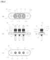
- the airtight terminal 20 which concerns on this indication is shown, (a) is a top view which shows an inner side, (b) is a front view, (c) is a bottom view which shows an outer side, (d) is a side view.
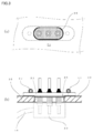
- the airtight terminal which concerns on this indication is shown in the state attached to the pressure resistant container, (a) is the top view which looked at the inner side of a pressure resistant container from which the connector of the electric motor was removed, (b) is the front view of the pressure resistant container.
- An airtight terminal includes a metal base having at least one sealing hole, a lead inserted through the sealing hole of the metal base, and an insulating material that hermetically seals the metal base and the lead. And a heat insulator provided on at least a part of the surface of the airtight terminal, which is located on the inner side in a state where the airtight terminal is attached to the pressure container and is in contact with the refrigerant sealed in the pressure container. There is.
- the predetermined surface of the heat insulator may be provided with a protrusion that circulates around the outer periphery having an outer diameter matching the inner diameter of the wiring connector to the electric motor. Since the exposed surface of the inner side of the airtight terminal is covered with the heat insulator, the refrigerant does not come into direct contact with at least the metal surface of the airtight terminal covered with the heat insulator. For this reason, the surfaces of the metal base and the leads on the inner side of the airtight terminal covered with the heat insulating body are not directly cooled by the refrigerant, so that dew condensation can be suppressed on the outer side of the airtight terminal.
- the heat insulator according to the present invention is made of an electric insulating material having resistance to refrigerant and oil.
- the heat insulating material can be made of a material selected from rubber, elastomer, and plastic, or a composite material or composite structure in which rubber, elastomer, and plastic are combined.
- a material for the heat insulator for example, HNBR (hydrogenated nitrile rubber), EPDM (ethylene-propylene-diene rubber), epoxy resin and PTFE (polytetrafluoroethylene resin) can be preferably used.
- Carbon black may be added as a stabilizer to prevent deterioration of the physical properties of the heat insulator. However, if the content of carbon black is too large, the electrical insulation property and withstand voltage property of the heat insulator may deteriorate.
- the amount of carbon black added is infinitely reduced in order to satisfy the required characteristics of the electric insulation and withstand voltage of the airtight terminal. For example, generally, when adding refrigerant resistance and oil resistance to HNBR rubber, carbon black added in the range of several% to less than 10% is used, but it is used for the heat insulator for the airtight terminal of the present embodiment.
- HNBR is either carbon black-free or carbon black-less to improve insulation.
- the HNBR used for the airtight terminal of the present embodiment has a lower carbon black content than usual. It is preferable that 1 to 5 mass% of one or more kinds of inorganic fillers of silica and magnesium silicate are added to this HNBR.
- the heat insulating composition for the hermetic terminal comprises a monophenolic antioxidant having a basic skeleton of one phenolic hydroxyl group in one aromatic ring, and two aromatic rings each having a phenolic group.
- a monophenolic antioxidant having a basic skeleton of one phenolic hydroxyl group in one aromatic ring and two aromatic rings each having a phenolic group.
- Any one or more of hindered phenolic antioxidants (oxidation: bisphenol-based antioxidant having a basic skeleton of one hydroxyl group, polyphenolic antioxidant having a basic skeleton of two phenolic hydroxyl groups in one aromatic ring) It is preferable to use the one which further contains less than 10 mass% of (inhibitor).
- the airtight terminal 10 of the present disclosure hermetically seals the metal base 11 having a sealing hole, the lead 12 penetrating the sealing hole of the metal base 11, and the metal base 11 and the lead 12.
- a glass insulating material 13 to be sealed and a heat insulating body 14 are provided.
- the heat insulator 14 is located on the inner side in a state where the airtight terminal 10 is attached to the pressure-resistant container 35 and is in contact with the refrigerant sealed in the pressure-resistant container 35. Cover.
- the airtight terminal 10 is airtightly fixed to the terminal mounting hole 36 of the pressure vessel 35 accommodating the electric motor together with the refrigerant and the lubricating oil by a fixing means such as a screw 37.
- a protrusion (indicated by reference numeral 210 in FIG. 2) that surrounds the outer periphery of the heat insulating body 14 may be provided in the portion that covers the lead 12.
- the protrusion has an outer diameter that matches the inner diameter of a connector 39 connected to the wiring cord 38 of the electric motor arranged inside the pressure-resistant container 35, and prevents the refrigerant and the lubricating oil from entering the inner diameter portion of the connector 39.
- the heat insulator 14 is provided so as to cover at least the entire surface of the airtight terminal 10 inside the terminal mounting hole 36 provided in the pressure-resistant container 35, except for the tip end of the inner lead 12.
- the tip of the inner side lead 12 is entirely inserted into the connector 39 for connection to the electric motor, so that the metal base of the airtight terminal 10 and the surface of the lead are not contacted with the cooling medium and cooled.
- the heat insulating body 14 may be made of any material as long as it is an electrical insulating material having a refrigerant resistance and an oil resistance.
- rubber such as HNBR or EPDM is suitable as the material of the heat insulator 14.
- a heat insulator 14 such as HNBR having a slightly inferior electric insulation property of 10 11 [ ⁇ cm]
- a carbon black-free or carbon black-less carbon black-reduced composition is used, and silica and silicic acid are added. It is preferable to add 1 to 5 mass% of any one or more inorganic fillers of magnesium.
- one containing at least one kind of a hindered phenol anti-aging agent selected from the group consisting of monophenol anti-oxidants, bisphenol anti-oxidants and polyphenol anti-oxidants in an amount of less than 10% by mass.
- the airtight terminal 10 of the present disclosure at least a portion that comes into contact with the refrigerant is provided with the refrigerant-resistant and oil-resistant heat insulating body 14 coating, and the heat insulating body 14 is provided with the electric insulation property, so that not only dew condensation is prevented.
- the creeping distance between the inner metal base 11 and the lead 12 can be increased to simultaneously improve the tracking resistance, electrical insulation and voltage resistance of the airtight terminal 10.
- the outer diameter of the heat insulating body 14 that covers the outer circumference of the lead 12 on the inner side is matched with the inner diameter of the connector 39 to which the lead 12 is attached. It is possible to seal the inside of the connector including the sealant so that lubricating oil (particularly PAG [polyalkylene glycol] oil has a low insulating property) which is a low insulator does not enter. This can prevent the insulation of the airtight terminal 10 from being lowered by the lubricating oil.
- lubricating oil particularly PAG [polyalkylene glycol] oil has a low insulating property
- a hermetic terminal 10 of Example 1 is a carbon steel metal having a plurality of through holes 100 provided for screwing and three sealing holes arranged in a straight line.
- Base 11 lead 12 made of Fe-Cr iron-based alloy that is inserted into the sealing hole of metal base 11, insulating material 13 of borosilicate glass that hermetically seals metal base 11 and lead 12, and heat insulator 14 and.
- the heat insulator 14 is a coating that covers the surfaces of the metal base 11, the lead 12, and the insulating material 13 located on the inner side and in contact with the refrigerant in the state where the airtight terminal 10 is attached to the pressure resistant container, and is made of HNBR. Is.
- a part of the heat insulator 14 extends along the surface of the lead 12 on the inner side (FIG. 1A), and covers the lead 12 excluding the tip portion.
- the other part of the heat insulating body 14 covers the entire surface of the insulating material 13, and further, beyond the end of the sealing hole of the metal base 11, the surface of the metal base 11 is attached to the surface of the airtight terminal 10. The coating is performed over the range up to the inner wall surface of the hole 36.
- the tip is used because it is inserted into the connector 39 wired to the electric motor in the pressure vessel 35 shown in FIG. Not exposed to the surface in the state.
- the refrigerant and the lubricating oil are prevented from directly contacting the surface of the metal base 11 of the airtight terminal 10 and the glass insulating material 13. Therefore, the surfaces of the metal base 11 and the leads 12 of the airtight terminal 20 are not directly cooled by the refrigerant, and it is possible to prevent dew condensation on the surface of the airtight terminal 10 on the outer side (FIG. 1C).
- the HNBR of the heat insulator 14 is a blended composition in which carbon black free or carbon black-less carbon black is reduced, and 1 to 5 mass% of at least one kind of silica and magnesium silicate is added to the HNBR, and monophenol is further added. Insulation is improved by using one containing at least one kind of hindered phenolic antioxidant, which is one or more kinds of antioxidants, bisphenolic antioxidants and polyphenolic antioxidants. .. By increasing the creepage distance between the metal base 11 on the inner side and the leads 12, it is possible to improve tracking resistance, electrical insulation and voltage resistance.
- the airtight terminal 20 of the second embodiment according to the present disclosure is a carbon steel metal having a plurality of through holes 200 provided for screwing and three sealing holes arranged in a straight line.
- the heat insulator 24 is a coating that covers the surfaces of the metal base 21, the leads 22 and the insulating material 23 located on the inner side and in contact with the refrigerant in a state where the airtight terminal 20 is attached to the pressure resistant container, and is made of EPDM. Is.
- a part of the heat insulating body 24 extends along the surface of the lead 22 on the inner side (FIG. 2A) and covers the lead 22 except for the tip portion.
- the other part of the heat insulating body 24 covers the entire surface of the insulating material 23, further extends beyond the sealing hole end of the metal base 21, and reaches the inner wall surface of the terminal mounting hole 36 to which the surface of the metal base 21 is attached. Coating over a range of up to.
- a plurality of protrusions 210 that surround the outer periphery of the heat insulating body 24 are provided at intervals on the portion of the heat insulating body 24 that covers the lead 22.
- the protrusion 210 has an outer diameter that matches the inner diameter of the connector wired to the electric motor arranged inside the pressure-resistant container to which the airtight terminal 20 is attached.
- the protrusion 210 prevents the refrigerant and the lubricating oil from entering the inner diameter portion of the connector, and also prevents the connector from falling off.
- the refrigerant and the lubricating oil are prevented from directly contacting the surface of the metal base 21 of the airtight terminal and the glass insulating material 23. Therefore, the surfaces of the metal base 21 and the leads 22 of the airtight terminal 20 are not cooled by the coolant, and it is possible to prevent dew condensation on the outer side (FIG. 2C) of the airtight terminal 20.
- the airtight terminal 20 of the second embodiment uses EPDM for the heat insulator 24, it is possible to satisfy the refrigerant resistance, particularly the oil resistance to POE [polyol ester] oil. Furthermore, by using EPDM, it is possible to increase the creepage distance between the inner metal base 21 and the leads 22 and improve the tracking resistance, electrical insulation and voltage resistance.
- the airtight terminal according to the present disclosure is, as shown in FIG. 3, inserted into the terminal mounting hole 36 of the pressure resistant container 35 after electrically connecting the lead to the electric motor housed in the pressure resistant container 35 to which the airtight terminal is attached. It can be attached by being fastened with a screw 37 or the like.
- the lead of the airtight terminal according to the present disclosure can be coated with a desired plating on its surface.
- the lead and the metal base may be made of any material as long as it is a metal material that can be used for the hermetic terminal.
- the Fe—Cr alloy may be changed to Fe—Ni alloy, carbon steel, copper alloy, aluminum alloy, or the like.
- the insulating material described in the embodiments only needs to be capable of electrically insulating and hermetically sealing the lead and the metal base, and not limited to soda barium glass, any glass material can be used.
- a part of the insulating material may be formed of different glass materials, if necessary. If necessary, part or all of the glass material may be replaced with a resin material such as an epoxy resin.
- the present disclosure can be used for airtight terminals, and particularly for vehicle-mounted airtight terminals.
Landscapes
- Engineering & Computer Science (AREA)
- Physics & Mathematics (AREA)
- General Engineering & Computer Science (AREA)
- Spectroscopy & Molecular Physics (AREA)
- Mechanical Engineering (AREA)
- Power Engineering (AREA)
- Thermal Sciences (AREA)
- Manufacturing & Machinery (AREA)
- Chemical & Material Sciences (AREA)
- Dispersion Chemistry (AREA)
- Motor Or Generator Frames (AREA)
- Compressor (AREA)
- Connections Arranged To Contact A Plurality Of Conductors (AREA)
- Insulating Bodies (AREA)
- Gasket Seals (AREA)
- Manufacturing Of Electrical Connectors (AREA)
- Organic Insulating Materials (AREA)
- Connector Housings Or Holding Contact Members (AREA)
Abstract
Description
上記断熱体は、ゴム、エラストマーおよびプラスチックから選択された材料、または、ゴム、エラストマーおよびプラスチックを複合させた複合材若しくは複合構成体で構成してもよい。
上記突起は、上記耐圧容器の内側に配置された電動機の配線コードに繋がるコネクタの内径に合致する外径を有し、上記コネクタの内径部への冷媒および潤滑油の進入を阻止してもよい。
複数の上記突起は、互いに間隔をあけて設けられてもよい。
上記金属ベースは、直線上に配置した複数の上記封着孔を有してもよい。
Claims (18)
- 少なくとも1個の封着孔を有する金属ベースと、
前記金属ベースの前記封着孔に挿通したリードと、
前記金属ベースと前記リードとを気密に封着する絶縁材と、
この気密端子が耐圧容器に取り付けられた状態においてインナー側に位置して前記耐圧容器に封入された冷媒と接触する前記気密端子の表面の少なくとも一部に設けられた断熱体とを備えた、気密端子。 - 前記断熱体は、耐冷媒性および耐油性を有する電気絶縁材からなる、請求項1に記載の気密端子。
- 前記断熱体は、ゴム、エラストマーおよびプラスチックから選択された材料、または、ゴム、エラストマーおよびプラスチックを複合させた複合材若しくは複合構成体からなる、請求項1または請求項2に記載の気密端子。
- 前記断熱体は、エポキシ樹脂およびPTFE(ポリテトラフルオロエチレン樹脂)から選択されたプラスチックからなる、請求項1から請求項3のいずれか1項に記載の気密端子。
- 前記断熱体は、HNBR(水素化ニトリルゴム)およびEPDM(エチレン-プロピレン-ジエンゴム)から選択されたゴムからなる、請求項1から請求項3のいずれか1項に記載の気密端子。
- 前記断熱体を構成する前記ゴムは、カーボンブラックフリーまたはカーボンブラックレスである、請求項5に記載の気密端子。
- 前記ゴムには、シリカおよび珪酸マグネシウムから選択された1種類以上の無機フィラーが1~5質量%添加されている、請求項6に記載の気密端子。
- 前記ゴムには、モノフェノール系酸化防止剤、ビスフェノール系酸化防止剤およびポリフェノール系酸化防止剤から選択された1種類以上のヒンダードフェノール系老化防止剤が10質量%未満添加されている、請求項6または請求項7に記載の気密端子。
- 前記断熱体は、少なくともインナー側に位置する前記リードの表面に沿って延び前記リードの先端部を除いて被覆する部分を有する、請求項1から請求項8のいずれか1項に記載の気密端子。
- 前記断熱体の前記リードを被覆する部分は、その外周を周回する突起を有する、請求項9に記載の気密端子。
- 前記突起は、前記耐圧容器の内側に配置された電動機の配線コードに繋がるコネクタの内径に合致する外径を有し、前記コネクタの内径部への冷媒および潤滑油の進入を阻止した、請求項10に記載の気密端子。
- 前記突起は、複数設けられた、請求項10または請求項11に記載の気密端子。
- 複数の前記突起は、互いに間隔をあけて設けられた、請求項12に記載の気密端子。
- 前記断熱体は、前記金属ベースの表面を前記気密端子が前記耐圧容器に取り付けられた状態において前記耐圧容器の端子取付孔の内壁面に到達するまで被覆する部分を有する、請求項1から請求項13のいずれか1項に記載の気密端子。
- 前記断熱体は、少なくとも前記耐圧容器に設けられた端子取付孔の内側の前記気密端子の表面全体を、前記インナー側の前記リードの先端部を除いて隙間なく覆うように設けられ、前記先端部は、前記耐圧容器の内側に配置された電動機の配線コードに繋がるコネクタに挿入される部分である、請求項1から請求項14のいずれか1項に記載の気密端子。
- 前記金属ベースは、ネジ止めのため設けた複数の通孔を有する、請求項1から請求項15のいずれか1項に記載の気密端子。
- 前記金属ベースは、直線上に配置した複数の前記封着孔を有する、請求項1から請求項16のいずれか1項に記載の気密端子。
- 請求項1から請求項17のいずれか1項に記載の気密端子を備えた、耐圧容器。
Priority Applications (4)
| Application Number | Priority Date | Filing Date | Title |
|---|---|---|---|
| US17/283,106 US11936133B2 (en) | 2019-02-19 | 2020-02-18 | Hermetic terminal and pressure-resistant container |
| DE112020000088.5T DE112020000088B4 (de) | 2019-02-19 | 2020-02-18 | Hermetischer Anschluss und druckbeständiger Behälter |
| CN202080005599.1A CN112823242A (zh) | 2019-02-19 | 2020-02-18 | 气密端子及耐压容器 |
| KR1020217010233A KR102507413B1 (ko) | 2019-02-19 | 2020-02-18 | 기밀 단자 및 내압 용기 |
Applications Claiming Priority (2)
| Application Number | Priority Date | Filing Date | Title |
|---|---|---|---|
| JP2019-027673 | 2019-02-19 | ||
| JP2019027673A JP7013402B2 (ja) | 2019-02-19 | 2019-02-19 | 電動コンプレッサ用気密端子 |
Publications (1)
| Publication Number | Publication Date |
|---|---|
| WO2020171048A1 true WO2020171048A1 (ja) | 2020-08-27 |
Family
ID=72144281
Family Applications (1)
| Application Number | Title | Priority Date | Filing Date |
|---|---|---|---|
| PCT/JP2020/006206 Ceased WO2020171048A1 (ja) | 2019-02-19 | 2020-02-18 | 気密端子および耐圧容器 |
Country Status (6)
| Country | Link |
|---|---|
| US (1) | US11936133B2 (ja) |
| JP (1) | JP7013402B2 (ja) |
| KR (1) | KR102507413B1 (ja) |
| CN (1) | CN112823242A (ja) |
| DE (1) | DE112020000088B4 (ja) |
| WO (1) | WO2020171048A1 (ja) |
Cited By (2)
| Publication number | Priority date | Publication date | Assignee | Title |
|---|---|---|---|---|
| WO2022259597A1 (ja) * | 2021-06-11 | 2022-12-15 | ショット日本株式会社 | 気密端子および同気密端子の製造方法 |
| JP2022189682A (ja) * | 2021-06-11 | 2022-12-22 | ショット日本株式会社 | 気密端子および同気密端子の製造方法 |
Families Citing this family (7)
| Publication number | Priority date | Publication date | Assignee | Title |
|---|---|---|---|---|
| EP3936722B1 (en) * | 2020-07-06 | 2024-09-04 | Schott Ag | Housing part, especially housing part in particular for an electronic housing, preferably e-compressor terminal |
| JP7513552B2 (ja) * | 2021-03-11 | 2024-07-09 | ショット アクチエンゲゼルシャフト | 気密端子の接続具および気密端子 |
| DE102022110839A1 (de) * | 2021-05-10 | 2022-11-10 | Hanon Systems | Durchführungs- und Abdichtungsanordnung |
| USD1060265S1 (en) * | 2021-05-17 | 2025-02-04 | Schott Japan Corporation | Hermetic terminal |
| CN114696523A (zh) * | 2022-05-09 | 2022-07-01 | 华域三电汽车空调有限公司 | 一种电动压缩机电机侧端子密封防护结构及电动压缩机 |
| EP4428368B1 (en) * | 2023-03-07 | 2025-01-15 | Schott Ag | Electrical feedthrough assembly |
| EP4717918A1 (en) | 2024-09-25 | 2026-04-01 | Schott Ag | Electrical feedthrough assembly |
Citations (6)
| Publication number | Priority date | Publication date | Assignee | Title |
|---|---|---|---|---|
| JPS519697Y1 (ja) * | 1971-09-29 | 1976-03-15 | ||
| JPH03114582U (ja) * | 1990-03-06 | 1991-11-25 | ||
| JPH04132885A (ja) * | 1990-09-20 | 1992-05-07 | Nec Kansai Ltd | 気密端子及び圧縮機 |
| JPH05144493A (ja) * | 1991-11-18 | 1993-06-11 | Matsushita Refrig Co Ltd | 密閉型圧縮機の気密端子カバー |
| JPH06185463A (ja) * | 1990-03-21 | 1994-07-05 | Tecumseh Prod Co | 電気絶縁性反トラッキング・キャップ付き気密タ−ミナル |
| JP2010168914A (ja) * | 2009-01-20 | 2010-08-05 | Mitsubishi Heavy Ind Ltd | 電動圧縮機 |
Family Cites Families (23)
| Publication number | Priority date | Publication date | Assignee | Title |
|---|---|---|---|---|
| JPS519697B2 (ja) * | 1973-06-12 | 1976-03-29 | ||
| US4830630A (en) | 1988-08-22 | 1989-05-16 | Hilliard Dozier | Hermetically sealed electrical terminal |
| JPH0796111B2 (ja) * | 1989-09-28 | 1995-10-18 | 株式会社彦間製作所 | 屎尿乾燥装置 |
| US5017740A (en) | 1990-04-02 | 1991-05-21 | Emerson Electric Co. | Fused hermetic terminal assembly including a pin guard and lead wire end connection securing device associated therewith |
| JP3842828B2 (ja) * | 1994-09-16 | 2006-11-08 | 三洋電機株式会社 | 密閉型電動圧縮機 |
| DE10117976A1 (de) | 2001-01-25 | 2002-08-22 | Siemens Ag | Einrichtung zur Durchführung von elektrischen Leitungen durch die Wandung eines Kraftstoffbehälters |
| US7197892B2 (en) | 2003-06-11 | 2007-04-03 | Denso Corporation | Encapsulated electrically driven compressor |
| JP3114582U (ja) | 2005-07-08 | 2005-10-27 | 日本工機株式会社 | ハンガー式伸縮門扉 |
| KR101241629B1 (ko) * | 2008-05-30 | 2013-03-11 | 가부시키가이샤 우부카타 세이사쿠쇼 | 열응동 개폐기 |
| JP5278956B2 (ja) | 2009-04-08 | 2013-09-04 | エヌイーシー ショット コンポーネンツ株式会社 | 高耐圧気密端子およびその製造方法 |
| DE102010043773B4 (de) | 2010-01-29 | 2014-05-22 | Halla Visteon Climate Control Corporation 95 | Elektrische Durchführung für Hermetikverdichter |
| JP5944169B2 (ja) * | 2012-01-20 | 2016-07-05 | サンデンホールディングス株式会社 | 電動圧縮機 |
| KR101513239B1 (ko) | 2013-11-21 | 2015-05-15 | 씨알에스(주) | 밀폐형 압축기용 밀봉 단자 |
| JP6282506B2 (ja) | 2014-03-26 | 2018-02-21 | サンデンホールディングス株式会社 | 電動圧縮機 |
| JP6449552B2 (ja) * | 2014-03-27 | 2019-01-09 | ショット日本株式会社 | ガラスフリット焼成膜を有する気密端子 |
| CN105375129B (zh) | 2014-08-27 | 2018-09-07 | 珠海格力节能环保制冷技术研究中心有限公司 | 一种玻封接线柱 |
| KR102583934B1 (ko) | 2016-09-08 | 2023-10-05 | 한온시스템 주식회사 | 압축기 |
| DE112016004914T5 (de) | 2016-04-22 | 2018-07-12 | Hanon Systems | Verdichter |
| KR102517731B1 (ko) | 2016-04-22 | 2023-04-05 | 한온시스템 주식회사 | 압축기 |
| CN206098769U (zh) | 2016-09-07 | 2017-04-12 | 深圳市南方源芯电气有限公司 | 汽车空调压缩机接线板电流传导装置 |
| CN207282748U (zh) | 2017-10-10 | 2018-04-27 | 潮州三环(集团)股份有限公司 | 一种二氧化碳压缩机用接线端子及其组件 |
| JP7231339B2 (ja) | 2018-06-01 | 2023-03-01 | ショット日本株式会社 | 気密端子 |
| DE102019126499A1 (de) | 2019-10-01 | 2021-04-01 | Hanon Systems | Dichtungs-Isolier-Anordnung für eine Vorrichtung zum Antreiben eines Verdichters und Vorrichtung zum Antreiben eines Verdichters |
-
2019
- 2019-02-19 JP JP2019027673A patent/JP7013402B2/ja active Active
-
2020
- 2020-02-18 WO PCT/JP2020/006206 patent/WO2020171048A1/ja not_active Ceased
- 2020-02-18 KR KR1020217010233A patent/KR102507413B1/ko active Active
- 2020-02-18 DE DE112020000088.5T patent/DE112020000088B4/de active Active
- 2020-02-18 CN CN202080005599.1A patent/CN112823242A/zh active Pending
- 2020-02-18 US US17/283,106 patent/US11936133B2/en active Active
Patent Citations (6)
| Publication number | Priority date | Publication date | Assignee | Title |
|---|---|---|---|---|
| JPS519697Y1 (ja) * | 1971-09-29 | 1976-03-15 | ||
| JPH03114582U (ja) * | 1990-03-06 | 1991-11-25 | ||
| JPH06185463A (ja) * | 1990-03-21 | 1994-07-05 | Tecumseh Prod Co | 電気絶縁性反トラッキング・キャップ付き気密タ−ミナル |
| JPH04132885A (ja) * | 1990-09-20 | 1992-05-07 | Nec Kansai Ltd | 気密端子及び圧縮機 |
| JPH05144493A (ja) * | 1991-11-18 | 1993-06-11 | Matsushita Refrig Co Ltd | 密閉型圧縮機の気密端子カバー |
| JP2010168914A (ja) * | 2009-01-20 | 2010-08-05 | Mitsubishi Heavy Ind Ltd | 電動圧縮機 |
Cited By (3)
| Publication number | Priority date | Publication date | Assignee | Title |
|---|---|---|---|---|
| WO2022259597A1 (ja) * | 2021-06-11 | 2022-12-15 | ショット日本株式会社 | 気密端子および同気密端子の製造方法 |
| JP2022189682A (ja) * | 2021-06-11 | 2022-12-22 | ショット日本株式会社 | 気密端子および同気密端子の製造方法 |
| JP7577636B2 (ja) | 2021-06-11 | 2024-11-05 | ショット アクチエンゲゼルシャフト | 気密端子および同気密端子の製造方法 |
Also Published As
| Publication number | Publication date |
|---|---|
| KR102507413B1 (ko) | 2023-03-09 |
| JP7013402B2 (ja) | 2022-01-31 |
| DE112020000088B4 (de) | 2026-03-19 |
| KR20210046805A (ko) | 2021-04-28 |
| DE112020000088T5 (de) | 2021-06-02 |
| JP2020136061A (ja) | 2020-08-31 |
| US11936133B2 (en) | 2024-03-19 |
| US20210344139A1 (en) | 2021-11-04 |
| CN112823242A (zh) | 2021-05-18 |
Similar Documents
| Publication | Publication Date | Title |
|---|---|---|
| US11936133B2 (en) | Hermetic terminal and pressure-resistant container | |
| US11417983B2 (en) | Airtight terminal | |
| KR102795694B1 (ko) | 기밀 단자 및 기밀 단자의 제조 방법 | |
| US6779989B2 (en) | Method for connecting compressor with built-in electric motor and external wiring, connection device used therefor, and compressor with built-in electric motor using the same | |
| CN102011729A (zh) | 马达驱动压缩机 | |
| US20140294624A1 (en) | Motor-driven compressor | |
| JP2022141770A (ja) | 気密端子 | |
| CN117334475B (zh) | 一种具有散热防护结构的铝电解电容 | |
| JP2008101862A (ja) | 電装品箱 | |
| JP7132195B2 (ja) | 気密端子 | |
| JP4916421B2 (ja) | 電動圧縮機の端子装置 | |
| CN112564408A (zh) | 一种密封型高电压直流无刷外转子风扇 | |
| CN112228353A (zh) | 一种污水泵密封组件及污水泵 | |
| CN101666306A (zh) | 冷冻机用压缩机密封端子 | |
| JP7349955B2 (ja) | 気密端子および電動圧縮機およびその気密端子の配線部封止方法 | |
| CN207251353U (zh) | 一种标准动车组变压器冷却风机的驱动双速电机 | |
| CN114294231A (zh) | 一种涡旋压缩机壳体结构 | |
| JP7577636B2 (ja) | 気密端子および同気密端子の製造方法 | |
| CN210136680U (zh) | 一种散热led显示屏 | |
| CN219163148U (zh) | 油隔膜呼吸装置及无局放试验变压器 | |
| CN216625474U (zh) | 一种三相异步电动机用端盖 | |
| CN221406710U (zh) | 户外防水高清显示模组 | |
| CN224134823U (zh) | 压缩机及制冷设备 | |
| CN104110530B (zh) | 隔热密封装置和空调器 | |
| CN202918110U (zh) | 制冷电机低压接线端子 |
Legal Events
| Date | Code | Title | Description |
|---|---|---|---|
| 121 | Ep: the epo has been informed by wipo that ep was designated in this application |
Ref document number: 20758687 Country of ref document: EP Kind code of ref document: A1 |
|
| WWE | Wipo information: entry into national phase |
Ref document number: 112020000088 Country of ref document: DE |
|
| WWE | Wipo information: entry into national phase |
Ref document number: 2101001999 Country of ref document: TH |
|
| ENP | Entry into the national phase |
Ref document number: 20217010233 Country of ref document: KR Kind code of ref document: A |
|
| 122 | Ep: pct application non-entry in european phase |
Ref document number: 20758687 Country of ref document: EP Kind code of ref document: A1 |
|
| WWG | Wipo information: grant in national office |
Ref document number: 112020000088 Country of ref document: DE |