WO2020171049A1 - Procédé de codage de signal acoustique, procédé de décodage de signal acoustique, programme, dispositif de codage, système acoustique et dispositif de complexation - Google Patents
Procédé de codage de signal acoustique, procédé de décodage de signal acoustique, programme, dispositif de codage, système acoustique et dispositif de complexation Download PDFInfo
- Publication number
- WO2020171049A1 WO2020171049A1 PCT/JP2020/006211 JP2020006211W WO2020171049A1 WO 2020171049 A1 WO2020171049 A1 WO 2020171049A1 JP 2020006211 W JP2020006211 W JP 2020006211W WO 2020171049 A1 WO2020171049 A1 WO 2020171049A1
- Authority
- WO
- WIPO (PCT)
- Prior art keywords
- signal
- masking
- sound
- sound source
- masking threshold
- Prior art date
- Legal status (The legal status is an assumption and is not a legal conclusion. Google has not performed a legal analysis and makes no representation as to the accuracy of the status listed.)
- Ceased
Links
Images



Classifications
-
- H—ELECTRICITY
- H04—ELECTRIC COMMUNICATION TECHNIQUE
- H04S—STEREOPHONIC SYSTEMS
- H04S7/00—Indicating arrangements; Control arrangements, e.g. balance control
- H04S7/30—Control circuits for electronic adaptation of the sound field
- H04S7/301—Automatic calibration of stereophonic sound system, e.g. with test microphone
-
- G—PHYSICS
- G10—MUSICAL INSTRUMENTS; ACOUSTICS
- G10L—SPEECH ANALYSIS TECHNIQUES OR SPEECH SYNTHESIS; SPEECH RECOGNITION; SPEECH OR VOICE PROCESSING TECHNIQUES; SPEECH OR AUDIO CODING OR DECODING
- G10L19/00—Speech or audio signals analysis-synthesis techniques for redundancy reduction, e.g. in vocoders; Coding or decoding of speech or audio signals, using source filter models or psychoacoustic analysis
- G10L19/008—Multichannel audio signal coding or decoding using interchannel correlation to reduce redundancy, e.g. joint-stereo, intensity-coding or matrixing
-
- H—ELECTRICITY
- H04—ELECTRIC COMMUNICATION TECHNIQUE
- H04R—LOUDSPEAKERS, MICROPHONES, GRAMOPHONE PICK-UPS OR LIKE ACOUSTIC ELECTROMECHANICAL TRANSDUCERS; ELECTRIC HEARING AIDS; PUBLIC ADDRESS SYSTEMS
- H04R5/00—Stereophonic arrangements
- H04R5/02—Spatial or constructional arrangements of loudspeakers
-
- G—PHYSICS
- G10—MUSICAL INSTRUMENTS; ACOUSTICS
- G10L—SPEECH ANALYSIS TECHNIQUES OR SPEECH SYNTHESIS; SPEECH RECOGNITION; SPEECH OR VOICE PROCESSING TECHNIQUES; SPEECH OR AUDIO CODING OR DECODING
- G10L19/00—Speech or audio signals analysis-synthesis techniques for redundancy reduction, e.g. in vocoders; Coding or decoding of speech or audio signals, using source filter models or psychoacoustic analysis
- G10L19/02—Speech or audio signals analysis-synthesis techniques for redundancy reduction, e.g. in vocoders; Coding or decoding of speech or audio signals, using source filter models or psychoacoustic analysis using spectral analysis, e.g. transform vocoders or subband vocoders
- G10L19/032—Quantisation or dequantisation of spectral components
- G10L19/035—Scalar quantisation
-
- H—ELECTRICITY
- H04—ELECTRIC COMMUNICATION TECHNIQUE
- H04S—STEREOPHONIC SYSTEMS
- H04S2420/00—Techniques used stereophonic systems covered by H04S but not provided for in its groups
- H04S2420/01—Enhancing the perception of the sound image or of the spatial distribution using head related transfer functions [HRTF's] or equivalents thereof, e.g. interaural time difference [ITD] or interaural level difference [ILD]
Definitions
- the present invention particularly relates to an audio signal encoding method, an audio signal decoding method, a program, an encoding device, an audio system, and a compounding device.
- bit allocation that adaptively allocates the number of bits in the quantization for each channel of the audio signals input to a plurality of channels on the time axis or the frequency axis.
- bit allocation bit allocation
- MPEG-2 AAC, MPEG-4 AAC, and MP3 which are used as standard
- the auditory masking effect on the frequency axis is used in this bit allocation.
- Patent Document 1 describes an example of a technique of acoustic signal coding that uses the auditory masking effect.
- a threshold value for masking effect bit allocation (hereinafter referred to as a masking threshold value) is calculated in order to utilize the auditory masking effect.
- the present invention has been made in view of such a situation, and an object thereof is to solve the above problems.
- the acoustic signal encoding method of the present invention is an acoustic signal encoding method for encoding acoustic signals of a plurality of channels, which is executed by an encoding device, and calculates a masking threshold value corresponding to a spatial masking effect of hearing. Then, the amount of information to be assigned to each of the channels is determined based on the calculated masking threshold value, and the acoustic signals of the plurality of channels are encoded by the assigned amount of information.
- a program of the present invention is a program executed by an encoding device, which encodes acoustic signals of a plurality of channels, and causes the encoding device to calculate a masking threshold value corresponding to an auditory spatial masking effect, According to the calculated masking threshold value, the amount of information to be assigned to each of the channels is determined, and the acoustic signals of the plurality of channels are encoded with the assigned amount of information.
- An encoding device of the present invention is an encoding device that encodes acoustic signals of a plurality of channels and/or sound source objects and position information of the sound source objects, and a masking threshold corresponding to a spatial masking effect of auditory sense.
- an information amount determination unit that determines the amount of information to be allocated to each of the channels and/or the sound source object by the masking threshold calculation unit that calculates the masking threshold value calculated by the masking threshold calculation unit.
- An encoding unit that encodes the acoustic signal and/or the sound source object and the position information of the sound source object with the allocated information amount, respectively.
- An audio system of the present invention is an audio system including the encoding device and a decoding device, wherein the decoding device includes a direction calculation unit that calculates a direction in which a listener is facing, and the direction calculation.
- the masking threshold value calculation unit of the encoding device sets the masking threshold value to a spatial distance and/or a spatial distance between each of the channels and/or each of the sound source objects with respect to the position and the direction of the listener. Alternatively, the calculation is performed corresponding to the spatial masking effect based on the direction.
- the amount of information to be assigned to each channel and/or sound source object is determined by a masking threshold corresponding to the spatial masking effect of the auditory sense, and the acoustic signals of a plurality of the channels and/or the sound source
- a decoding unit that decodes the sound source object into a sound signal.
- a masking threshold value corresponding to the spatial masking effect of the auditory sense is calculated, the calculated masking threshold value is used to determine the information amount for allocating the acoustic signals of a plurality of channels to each channel, and the allocated information amount It is possible to provide an audio signal encoding method capable of encoding an audio signal having a large number of channels at a sufficient bit rate by encoding with.
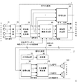
- FIG. 1 It is a system configuration diagram of an audio system according to an embodiment of the present invention. It is a flow chart of acoustic coding decoding processing concerning an embodiment of the invention. It is a conceptual diagram of the audio encoding/decoding process shown in FIG. It is a conceptual diagram of the audio encoding/decoding process shown in FIG. It is a conceptual diagram which shows the measurement system of the listening experiment which concerns on the Example of this invention. It is a conceptual diagram which shows the threshold value search in the listening experiment which concerns on the Example of this invention. It is a screen example of a response screen in the listening experiment according to the embodiment of the present invention.
- the audio system X is a system capable of acquiring audio signals of a plurality of channels, encoding them by the encoding device 1, transmitting them, decoding them by the decoding device 2, and reproducing them.
- the encoding device 1 is a device that encodes an acoustic signal.
- the encoding device 1 is, for example, a PC (Personal Computer), a server, an encoder board mounted on these, a dedicated encoder, or the like.
- the encoding device 1 of the present embodiment encodes acoustic signals of a plurality of channels, and/or sound source objects and position information of the sound source objects.
- the encoding device 1 corresponds to an audio encoding system such as MPEG-2 AAC, MPEG-4 AAC, MP3, Dolby (registered trademark) Digital, DTS (registered trademark), and has two channels, 5.1. Encoding is performed on acoustic signals of a plurality of channels such as channels, 7.1 channels, 22.2 channels and the like.
- the decoding device 2 is a device that decodes the acoustic signal encoded by the decoding device 2.
- the decryption device 2 is, for example, an HMD (Head-Mounted Display) for VR (Virtual Reality) or AR (Augmented Reality), a smartphone (Smart Phone), a dedicated game machine, a home TV, and a wireless connection. Headphones, virtual multi-channel headphones, equipment for movie theaters and public viewing venues, dedicated decoders and head tracking sensors, etc.
- the decoding device 2 decodes and reproduces the audio signal encoded by the encoding device 1 and transmitted by wire or wirelessly.
- the acoustic system X mainly includes a microphone array 10, a sound collector 20, a frequency domain converter 30, a masking threshold calculator 40, an information amount determiner 50, an encoder 60, a direction calculator 70, a transmitter 80, and a decoder.
- the conversion unit 90, the stereophonic sound reproducing unit 100, and the headphones 110 are included.
- the frequency domain conversion unit 30, the masking threshold value calculation unit 40, the information amount determination unit 50, and the encoding unit 60 function as the encoding device 1 (transmission side) of the present embodiment.
- the direction calculation unit 70, the transmission unit 80, the decoding unit 90, the stereophonic sound reproduction unit 100, and the headphones 110 function as the decoding device 2 (reception side) of the present embodiment.
- the microphone array 10 picks up sound in a sound space, which is a space where various sounds exist in various places. Specifically, for example, the microphone array 10 acquires sound waves in multiple directions of 360°. At this time, the directivity is controlled by the beam forming process and the beam is directed in each direction, whereby spatial sampling of the sound space is performed and a multi-channel audio beam signal can be obtained. Specifically, in the beam forming of the present embodiment, the phase difference of the sound waves that reach the microphones of the microphone array 10 is controlled by a filter, and the signal in the direction of arrival of each microphone is emphasized. Then, as spatial sampling, the sound field is spatially separated, and the sound is collected in multiple channels while including the spatial information.
- the sound collection unit 20 is a device such as a mixer that collects sounds of a plurality of channels and transmits them as an acoustic signal to the encoding device 1.
- the frequency domain transformation unit 30 cuts out the voice beam signal for each direction obtained by spatial sampling into a window (frame) of several microseconds to several tens of milliseconds, and performs DFT (discrete Fourier transform) or discrete Fourier transform (discrete Fourier transform).
- the time domain is transformed into the frequency domain by MDCT (Modified Discrete Cosine Transform).
- MDCT Modified Discrete Cosine Transform
- the frequency domain converter 30 outputs this frame as an acoustic signal of each channel. That is, the acoustic signal of this embodiment is a signal in the frequency domain.
- the masking threshold calculation unit 40 calculates a masking threshold corresponding to the auditory spatial masking effect from the acoustic signal of each channel converted by the frequency domain conversion unit 30. At this time, the masking threshold calculation unit 40 applies a model considering the spatial masking effect, and then calculates a masking threshold in the frequency domain.
- the calculation itself of the masking threshold value in the frequency domain can be realized by the method described in Non-Patent Document 1, for example.
- the masking threshold calculation unit 40 can acquire the sound source object and similarly calculate the masking threshold corresponding to the spatial masking effect of the auditory sense.
- This sound source object represents each of a plurality of acoustic signals generated from spatially different positions.
- This sound source object is, for example, an acoustic signal with position information. This may be, for example, an output signal of a microphone for recording each musical instrument of the orchestra, a sampled audio signal used in a game or the like, which is converted into an acoustic signal in the frequency domain.
- the masking threshold value calculation unit 40 calculates frequency masking by acquiring or converting an acoustic signal once collected and stored in a recording medium such as a flash memory, an HDD, or an optical recording medium. Is also possible.
- the masking threshold calculation unit 40 sets the masking threshold to the spatial distance between the channels and/or between the sound source objects and/or the positional direction information of the listener. Alternatively, it can be calculated corresponding to the spatial masking effect based on the direction. Alternatively, the masking threshold calculation unit 40 may calculate the masking threshold corresponding to the spatial masking effect based on the spatial distance and/or the direction between the channels and/or the sound source objects.
- the masking threshold calculation unit 40 has a greater influence on the masking threshold as the spatial distance and/or the direction between the channel and/or the sound source object are closer to each other, and has a greater influence on each other as the spatial distance and/or the direction between the sound source objects are closer to each other. It may be calculated corresponding to the spatial masking effect that becomes smaller.
- the masking threshold value calculation unit 40 influences the masking threshold value with respect to the spatial distance and/or the direction between the sound source objects with respect to the channels and/or the sound source objects that are located symmetrically with respect to the listener. It may be calculated corresponding to the spatial masking effect that changes the degree of.
- the masking threshold calculation unit 40 for a channel and/or sound source object located behind the listener with respect to the masking threshold, has the channel and/or object in front of the symmetrical position. It may be calculated corresponding to such a spatial masking effect.
- the masking threshold calculation unit 40 You may adjust by the following formula (1).
- ⁇ is the direction of the masker
- ⁇ is a constant controlled by the frequency of the masker
- ⁇ is the tone of the masker signal.
- x indicates a direction to be sought or a direction of a masky.
- the sound that interferes with the hearing is called “masker”, and the sound that interferes with the hearing is called “musky”.
- max is a function that returns the maximum value in the argument.
- f(x) of the equation (1) for example, a linear function such as a triangular wave shown in the following equation (2) can be used.
- x it is possible to use a desired orientation or a Muskie orientation.
- This azimuth corresponds to the beamforming direction of the microphone, the direction of the sound source object, and the like.
- f(x) it is possible to use other functions, for example, a function calculated from an actual masker or a result of a Muskey experiment.
- the masking threshold calculation unit 40 applies the masking threshold to the signals of the respective channels and/or the sound source objects depending on whether the signals of the respective channels and/or the sound source objects are tone-like signals or noise-like signals. It may be calculated corresponding to the spatial masking effect that changes the degree of influence.
- the information amount determination unit 50 determines the amount of information to be assigned to the sound source object based on the masking threshold value calculated by the masking threshold value calculation unit 40. In the present embodiment, as the information amount, bits are assigned to each acoustic signal based on the masking threshold. The information amount determination unit 50 calculates the average number of bits per sample by Perceptual Entropy (hereinafter referred to as “PE”) as the bit allocation corresponding to the masking threshold value calculated by the masking threshold value calculation unit 40. It is possible to
- the encoding unit 60 encodes the acoustic signals of a plurality of channels, and/or the sound source object and the position information of the sound source object with the respectively allocated information amount.
- the encoding unit 60 quantizes each acoustic signal based on the number of bits assigned by the information amount determination unit 50, and transmits it to the transmission path.
- this transmission path for example, Bluetooth (registered trademark), HDMI (registered trademark), WiFi, USB (Universal Serial Bus), or other wired or wireless information transmission means can be used. More specifically, it can be transmitted by peer-to-peer communication via a network such as the Internet or WiFi.
- the direction calculator 70 calculates the direction in which the listener is facing.
- the direction calculation unit 70 includes, for example, an acceleration sensor capable of head tracking, a gyro sensor, a geomagnetic sensor, and the like, and a circuit that converts the outputs of these to direction information. On this basis, the direction calculation unit 70 can calculate the position/direction information by adding the position information in consideration of the positional relationship between the listener and the sound source object or the acoustic signals of a plurality of channels to the calculated direction information.
- the transmitting unit 80 transmits the position/direction information calculated by the direction calculating unit 70 to the encoding device 1.
- the transmission unit 80 can send the position/direction information to the masking threshold calculation unit 40 so that the position/direction information can be received by, for example, wired or wireless transmission similar to the transmission path of the acoustic signal.
- the decoding unit 90 decodes acoustic signals of a plurality of channels and/or sound source objects encoded by the encoding device 1 into audio signals. For example, the decoding unit 90 first dequantizes the signal received from the transmission path. Next, the signal in the frequency domain is returned to the time domain by IDFT (Inverse Discrete Fourier Transform, inverse discrete Fourier transform, inverse discrete Fourier transform), IMDCT (Inverse Modified Discrete Cosine Transform, inverse modified discrete cosine transform), etc. Convert to channel audio signal.
- IDFT Inverse Discrete Fourier Transform, inverse discrete Fourier transform, inverse discrete Fourier transform
- IMDCT Inverse Modified Discrete Cosine Transform, inverse modified discrete cosine transform
- the stereophonic reproduction unit 100 converts the audio signal decoded by the decoding unit 90 into a stereophonic signal that reproduces the stereophonic sound for the listener.
- the stereophonic sound reproducing unit 100 regards the beam signal for each direction returned to the time domain as a signal emitted from a sound source in that direction and regards the beam direction as an HRTF (Head-Related Transfer Function, head). Partial transfer function).
- HRTF Head-Related Transfer Function, head). Partial transfer function.
- the HRTF expresses a change in sound caused by a peripheral object including the auricle, the human head, and the shoulder as a transfer function.
- the HRTF weights the convoluted signals for each beam direction and then adds the weighted signals to generate a two-channel binaural signal to be presented to the listener.
- the beam-direction-based weighting is a process of performing weighting such that the binaural signals that are the L signal and the R signal are closer to the binaural signals in the sound space to be reproduced.
- a binaural signal is generated by convolving and adding the HRTFs in the sound source direction to the respective sound sources existing in a certain sound space.
- the binaural signal is used as a target signal, and the output signal is weighted so that the binaural signal obtained as an output becomes equal to the target signal.
- the stereophonic sound reproducing unit 100 can update the HRTF by the position/direction information calculated by the direction calculating unit 70 in addition to the masking threshold described above, and can reproduce the stereophonic sound.
- the headphone 110 is a device for the listener to reproduce the sound that is decoded and stereophonicized.
- the headphone 110 includes a D/A converter, an amplifier, an electromagnetic driver, an earpiece worn by a user, and the like.
- the encoding device 1 and the decoding device 2 are, for example, as various circuits, an ASIC (Application Specific Processor), a DSP (Digital Signal Processor), a CPU (Central Processing Unit). , MPU (Micro Processing Unit), GPU (Graphics Processing Unit), etc.
- the encoding device 1 and the decoding device 2 use, as storage means, semiconductor memory such as ROM (Read Only Memory) and RAM (Random Access Memory), magnetic recording medium such as HDD (Hard Disk Drive), and optical recording. It includes a storage unit such as a medium. A control program for realizing each method according to the embodiment of the present invention is stored in this storage unit.
- the encoding device 1 and the decoding device 2 include display means such as a liquid crystal display and an organic EL display, input means such as a keyboard, a pointing device such as a mouse and a touch panel, a LAN board, a wireless LAN board, serial, parallel, and USB.
- display means such as a liquid crystal display and an organic EL display
- input means such as a keyboard, a pointing device such as a mouse and a touch panel, a LAN board, a wireless LAN board, serial, parallel, and USB.
- An interface such as (Universal Serial Bus) may be included.
- the encoding device 1 and the decoding device 2 execute the respective methods according to the embodiments of the present invention by using the hardware resources by being executed by the control unit mainly using various programs stored in the storage means. Can be realized using. It should be noted that a part or an arbitrary combination of the above-described configurations may be configured as an IC, a programmable logic, an FPGA (Field-Programmable Gate Array), or the like in terms of hardware or circuit.
- Step S101 the frequency domain conversion unit 30 of the encoding device 1 performs audio data acquisition processing.
- a sound collector goes to a stadium or the like and picks up sound using the microphone array 10.
- audio signals in each direction ( ⁇ ) centered on the microphone array 10 are acquired.
- the sound collecting side collects sound based on the concept of "spatial sampling". Spatial sampling is to spatially separate the sound field and collect sound in multiple channels. In the present embodiment, for example, a sound signal of a specific step, which is divided into left and right 0° to 360°, is picked up corresponding to a plurality of channels.
- the frequency domain conversion unit 30 cuts out the collected voice data, converts the time domain signal into a frequency domain signal by DFT, MDCT, or the like, and stores the acoustic signal in the storage unit.
- Step S201 the direction calculation unit 70 of the decoding device 2 performs the direction calculation process.
- the direction calculation unit 70 calculates the direction information of the listener and the position information of the acoustic data.
- Step S202 Next, the transmission unit 80 performs a direction transmission process.
- the transmission unit 80 transmits the position/direction information calculated by the direction calculation unit 70 to the encoding device 1.
- Step S102 the masking threshold calculation unit 40 of the encoding device 1 performs the masking threshold calculation processing.
- the masking threshold T is calculated in the frequency domain, the masking threshold of spatial masking described later is further calculated, and the bit allocation is determined. Therefore, the masking threshold calculation unit 40 first calculates the masking threshold T in the frequency band.
- the auditory masking effect is an effect in which one sound is hard to hear due to the presence of another sound.
- the sound that interferes with the hearing is referred to as “masker”, and the sound that interferes with the hearing is referred to as “musky”.
- the masking effect is roughly classified into frequency masking (simultaneous masking) and time masking (continuous masking).
- Frequency masking is a masking that occurs when a masker and a masky overlap in time
- time masking is a masking that occurs when they are apart in time.
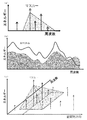
- the horizontal axis represents frequency and the vertical axis represents signal energy. That is, FIG.
- 3A is a graph of an example of a range and a threshold value of a spectrum (Maskey) masked by a masker when a certain spectrum (pure tone) included in a signal is used as a masker.
- the threshold value of the masky increases even near the frequency of the masker where no signal component exists.
- the frequency range in which the threshold value increases is not symmetrical with respect to the frequency of the masker, and the higher the frequency of the masky with respect to the masker, the easier it is to mask the sound of the lower frequency. Therefore, auditorily, a situation occurs in which the masker has not only the frequency of the masker but also the components spread on both sides thereof.
- Fig. 3(b) shows the concept of applying frequency masking in encoding.
- the horizontal axis represents frequency and the vertical axis represents signal energy.
- the thick black curve represents the spectrum of the signal.
- the gray curve represents the masking threshold.
- the filled area in FIG. 3B is a portion that is masked by frequency masking and is not perceived.
- the part that actually contributes to the perception of sound in FIG. 3B is the part sandwiched between the curve representing the spectrum of the signal and the curve representing the masking threshold.
- a frequency where the energy of the signal spectrum is smaller than the masking threshold value like the high frequency band in FIG. 3B does not contribute to the perception of sound.
- the curve representing the masking threshold over the entire band as shown in FIG. 3B is obtained by calculating the masking threshold for each frequency component using the knowledge of masking regarding a single spectrum or noise, and combining them. can get.
- the masking threshold calculation unit 40 convolves a masking threshold calculation formula (Spreading Function, hereinafter, referred to as “SF”) with the Bark spectrum as described in Patent Document 1, for example. Then, the masking threshold calculation unit 40 calculates the Spread masking threshold T spread using the Spectral Flatness measure (SFM) and the adjustment coefficient. Then, the masking threshold calculation unit 40 calculates the provisional threshold T by returning the Spread masking threshold T spread to the area of the Bark spectrum by deconvolution.
- SFM Spectral Flatness measure
- the masking threshold value calculation unit 40 divides the temporary threshold value T by the number of DFT spectra corresponding to each Bark index, and then compares the temporary threshold value T with the absolute threshold value to obtain the temporary threshold value T. Is converted to the final threshold value T final for frequency masking.
- the approximate expression T qf [dBSPL] of the absolute threshold at the frequency f (Hz) is calculated by the following equation (3).
- T qf 3.64 (f/1000) -0.8 -6.5 exp ⁇ -0.6 (f/1000-3.3) 2 ⁇ +10 -3 (f/1000) 4 +O LSB ...Equation (3)
- the masking threshold calculation unit 40 calculates the threshold T final in the i-th frequency band (final band) of frequency masking by the following formula (4).
- the masking threshold calculation unit 40 further calculates a masking threshold corresponding to the auditory spatial masking effect from the threshold T final of this frequency band. At this time, the masking threshold calculation unit 40 calculates the frequency masking threshold considering spatial masking, using the direction information of the acoustic signal.
- the masking threshold value of the own channel is calculated using only the signal component of the own channel. That is, in an audio signal having a plurality of channels, masking by the signals of channels other than the target channel is not considered for masking the target channel, and the masking threshold value is determined for each channel independently.
- the spatially sampled acoustic signal as used in the present embodiment has a large signal correlation between adjacent channels, and a portion having similar waveforms and a portion having similar waveforms are mixed.
- spatial masking in which the masking effect is extended to the spatial domain, is used for encoding the spatially sampled signal.
- the horizontal axis represents the spatial direction of the signal
- the depth represents the frequency
- the vertical axis represents the energy of the signal.
- the area inside the square pyramid at the foot of the masker signal represents the area that will be masked by this signal.
- the dimension of direction is added and the dimension is increased by one.
- the spatial direction includes an azimuth angle and an elevation angle.
- the curve representing the masking threshold is three-dimensional. In other words, masking occurs in the spatial direction, and a masked signal is generated.
- Such spatial masking involves masking the auditory central system where binaural information interacts.
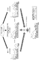
- FIG. 4 is an example of calculating a masking threshold value in which spatial masking is taken into consideration for signals in the i direction among signals in the N direction from 1 to N.
- the horizontal axis of each graph is frequency, and the vertical axis is signal energy.
- the black solid line represents the signal spectrum and the gray solid line represents the masking threshold calculated from them.
- the black broken line is obtained by weighting the masking threshold of the signal in each direction.
- the gray dotted line represents the masking threshold of the signal in the i direction, which takes into account all the masking by the signal in each direction.
- the present inventors created a masking model in consideration of spatial masking in an omnidirectional sound source based on the results of listening experiments of examples described later, and calculated as follows.
- the calculation procedure is as follows. First, for signals in each direction, a masking threshold is calculated in the same way as the conventional frequency domain masking. Next, in order to obtain the masking threshold value T in each of these directions, the weight to be multiplied by the masking threshold value in the frequency domain of each channel signal is calculated by the function T spatial ( ⁇ , x) corresponding to the above equation (1). , Respectively. However, the weighting of the masking threshold value of itself, i.e., the signal in the i-direction, is set to zero dB, that is, to 1 on the linear scale.
- the weighted omnidirectional masking thresholds are summed on a linear scale. Thereby, the masking threshold value of the signal in the i direction in consideration of the spatial masking is obtained.
- the function T spatial is a function that outputs the amount of attenuation of the masking threshold from the direction in which the masker exists in decibels when the direction of the masker and the direction of the masky are input as variables. Therefore, T spatial is determined so that the maximum value is 0 [dB] in the direction in which the masker exists.
- the orientation of the masker is [deg. ]
- the azimuth of the musky is x[deg. ]
- the function T spatial ( ⁇ , x) [dB] is calculated by the following equation (4-2).
- ⁇ and ⁇ are scaling coefficients
- max is a function that returns the maximum value in the argument.
- f is an arbitrary periodic function with a period of 360° that takes a maximum value at a phase of 0°.
- f(x) As the periodic function f(x), it is possible to use, for example, a triangular wave similar to the above equation (2).
- f(x ⁇ ) becomes 0 dB in the azimuth in which the masker exists, and the threshold change that minimizes the level in the azimuth opposite to that, that is, in the azimuth advanced by 180° Represent
- f(180-x- ⁇ ) is 0 dB in the azimuth symmetrical with respect to the azimuth where the masker is present, and is the threshold that the level is minimum in the azimuth opposite to that, that is, the azimuth advanced 180°. Shows the change.
- two functions f that are phase-matched so as to respectively represent “attenuation of the threshold value from the direction in which the masker exists” and “attenuation of the threshold value from the direction that is symmetrical to the direction in which the masker exists”
- the scaling factor ⁇ (0 ⁇ 1) is a masking effect that “the lower the frequency (center frequency) of the masker, the more noticeable the increase of the threshold value when the masky is in the symmetric direction with respect to the masker”. Is a coefficient for reflecting. ⁇ is determined so that it becomes closer to 1 as the frequency of the masker becomes lower and approaches 0 as the frequency of the masker becomes higher. By doing so, f(180-x- ⁇ ) can be scaled according to the frequency of the masker, and the degree of folding back of the threshold value on the frontal plane can be adjusted.
- the scaling coefficient ⁇ (0 ⁇ ) is a coefficient for reflecting the finding that “when the masker is a pure tone, the change in the threshold value depending on the direction of the masky is flat”. ⁇ is determined so that it becomes closer to 0 as the tone of the masker has a tone characteristic, and becomes larger as the tone of the masker has a noise characteristic. By doing so, it is possible to adjust the fluctuation range of the value of the entire function T spatial when ⁇ and x change, depending on whether the masker is pure tone or noise.
- the weight T by which the masking threshold value in the frequency domain of each channel signal is multiplied is applied.
- the masking threshold value in that direction (x direction) can be calculated (on the frequency axis).
- the information amount determination unit 50 performs information amount determination processing.
- the direction information of the spatially sampled signal is used to perform bit allocation in consideration of the spatial domain in the frequency domain.
- a masking effect is used to perform bit allocation considering the spatial area. Therefore, the information amount determination unit 50 determines the information amount to be assigned to each channel and/or sound source object based on the masking threshold value calculated by the masking threshold value calculation unit 40.
- a masking threshold corresponding to the auditory spatial masking effect it becomes possible to perform bit allocation on the frequency axis in consideration of the spatial region. That is, by using the auditory spatial masking effect, it is possible to reduce the number of bits of the signal required for transmission while maintaining the auditory quality.
- the information amount determination unit 50 calculates the bit allocation as the information amount by using PE, for example, in order to positively use the masking effect of hearing.
- a signal below the masking threshold has no meaningful information for human hearing, that is, the average information amount of a music signal is calculated as PE that can be buried in quantization noise.
- This PE can be calculated by the following equation (5).
- Step S104 the encoding unit 60 performs an encoding process.
- the encoding unit 60 encodes the acoustic signals of a plurality of channels, and/or the sound source object and the position information of the sound source object by the information amount respectively allocated.
- the encoded data is transmitted to the decoding device 2 on the receiving side. This transmission is performed by, for example, peer-to-peer communication. Alternatively, it may be downloaded as data or read by the decoding device 2 as a memory card or an optical recording medium.
- Step S203 the decoding unit 90 of the decoding device 2 performs the decoding process.
- the decoding unit 90 decodes acoustic signals of a plurality of channels and/or sound source objects encoded by the encoding device 1 into audio signals.
- the decoding device 2 is a smartphone or the like
- the acoustic signal transmitted by the encoding device 1 is decoded by a decoder such as a specific codec.
- the stereophonic sound reproducing unit 100 performs a stereophonic sound reproducing process.
- the stereophonic reproduction unit 100 converts the audio signal decoded by the decoding unit 90 into a stereophonic signal that reproduces the stereophonic sound for the listener.
- the stereophonic sound reproducing unit 100 reproduces a multi-channel audio signal as a 2-channel audio signal while including spatial information. This can be realized by adding the transfer characteristics of the sound from the sound source to the human ear to each audio signal and adding them in all directions. That is, the stereophonic sound reproducing unit 100 synthesizes sound signals for each direction and reproduces the sound signals using headphones.
- the head related transfer function (HRTF) corresponding to the direction of each audio signal is convoluted and converted into a two-channel sound signal.
- the stereophonic sound reproducing unit 100 adds, for example, the transfer characteristics of the HRTF corresponding to the direction of each signal to each audio signal, and outputs the sum of the signals in each of the L channel and the R channel. As a result, it is possible to easily reproduce the two-channel audio signal from the headphones without depending on the number of channels on the sound collecting side. With the above, the acoustic signal coding/decoding processing according to the embodiment of the present invention is completed.
- a sound field represented by a multi-channel signal is composed of a plurality of spatially dispersed sound sources. Regarding this, regarding the mutual masking effect and hearing when multiple sound sources are spatially arranged at the same time, its action and effect have not been clarified, and it has not been applied yet.
- the encoding device 1 is an encoding device that encodes acoustic signals of a plurality of channels, and/or a sound source object and position information of the sound source object.
- a masking threshold calculation unit 40 that calculates a masking threshold corresponding to the spatial masking effect of the auditory sense, and an information amount that determines the amount of information to be assigned to each channel and/or sound source object based on the masking threshold calculated by the masking threshold calculation unit 40.
- the present invention is characterized by including a determining unit 50 and an encoding unit 60 that encodes acoustic signals of a plurality of channels, and/or sound source objects and position information of the sound source objects with assigned information amounts.
- the spatial relationship between the channels is not taken into consideration. Therefore, in the case of an audio signal having a larger number of channels such as 22.2 channel sound, the compression is performed by bit allocation. However, the bit rate (bandwidth) at the time of transmission may be insufficient.
- the sound field represented by the multi-channel signal is composed of a plurality of spatially dispersed sound sources. Since the spatially sampled signal includes spatial information, it is possible to further reduce the number of transmission bits by performing bit allocation considering the spatial domain in addition to the conventional frequency domain.
- the bit rate can be reduced by obtaining a masking threshold value for a plurality of spatially scattered sound sources based on the mutual masking effect and performing bit allocation based on the threshold value. According to the experiments by the present inventors, it is possible to reduce the bit rate by 5 to 20% compared with the conventional one.
- An audio system X of the present invention is an audio system that includes the encoding device 1 and the decoding device 2 described above, and the decoding device 2 calculates the direction in which the listener is facing. And a transmission unit 80 that transmits the direction calculated by the direction calculation unit 70 to the encoding device 1, an acoustic signal of a plurality of channels encoded by the encoding device 1, and/or a sound source object is decoded into an audio signal.
- the masking threshold value calculation unit 40 of the encoding device 1 includes a decoding unit 90 for converting the spatial distance and/or the spatial distance between each channel and/or each sound source object with respect to the position and direction of the listener. It is characterized in that it is calculated corresponding to the spatial masking effect based on the direction.
- an auditory display that calculates direction information and controls the position of a sound image can be realized. That is, the position of the sound source of each channel, or the relative positional relationship between the position of the sound source object and the listener is fed back to the encoding device 1, and encoding is performed based on the positional relationship, and decoding is performed. It becomes possible. Accordingly, it is possible to provide an acoustic system that allows users to easily pick up, transmit, and play the 360° spherical sound space.
- 3D (three-dimensional) sound field reproduction technology binaural/trans-aural auditory display technology for enjoying music, broadcasting/movie contents as surround sound with headphones or two front speakers, 5.1-channel for home theater
- a sound field reproduction technology that simulates the sound field of a real hall or theater in a 7.1-channel surround playback environment has been developed.
- 3D sound field reproduction technology using wave field synthesis with a speaker array is also in progress.
- sound collection and multi-channel content expression have become common.
- a 3D sound reproduction technique although embodiments relating to a head related transfer function and localization have been actively carried out, the relation with spatial masking has not been examined.
- the decoding device 2 is a stereophonic sound reproduction in which the audio signal decoded by the decoding unit 90 is converted into a stereophonic sound signal for reproducing the stereophonic sound for the listener. It is characterized by further including a section 100.
- an acoustic signal efficiently encoded by applying the interrelationship of a plurality of sound sources scattered in the sound field of the three-dimensional space and the masking effect to the spatial perception of the acoustic signal, It can be reproduced in two channels in association with the head related transfer function (HRTF).
- HRTF head related transfer function
- the acoustic signal encoding method of the present invention is characterized in that the masking threshold value is calculated corresponding to a spatial masking effect based on a spatial distance and/or a direction between each channel and/or each sound source object.
- the masking threshold value is calculated corresponding to a spatial masking effect based on a spatial distance and/or a direction between each channel and/or each sound source object.
- the masking threshold value has a greater influence on each other as the spatial distance and/or the direction between the channel and/or the sound source object become closer, and becomes smaller as the spatial distance and/or direction between the sound source objects become closer. It is characterized in that it is calculated corresponding to the dynamic masking effect.
- the spatial masking effect can be calculated. With such a spatial masking effect, more efficient encoding is possible and the data transmission bit rate can be reduced.
- the masking threshold has an effect on the mutual spatial distance and/or direction between the sound source objects for the channels and/or the sound source objects located at symmetrical positions with respect to the listener. It is characterized in that it is calculated corresponding to the spatial masking effect that changes the degree of.
- the spatial masking effect can be calculated by a model whose effect is not so small.
- the masking threshold is such that, for a channel and/or sound source object located at a position behind the listener, the channel and/or object exists in front of a symmetrical position. It is characterized in that it is calculated corresponding to the spatial masking effect. For a channel or sound source object that is configured in this way and is at a position behind the listener, a spatial masking effect that corresponds to a position that is symmetrical to the front and back and that channel or object exists in front of the mirror is used. It is possible to calculate the masking threshold value.
- the masking threshold value is calculated so that the sound source located behind the axis with the straight line connecting both ears as the axis moves to the front of the axis corresponding to the position of line symmetry about the axis.
- the masking threshold value of the signal of each channel and/or sound source object is determined according to whether the signal of each channel and/or sound source object corresponds to a tone-type signal or a noise-type signal. It is characterized in that it is calculated corresponding to a spatial masking effect that changes the degree of mutual influence. With this configuration, as a spatial masking effect, the degree of influence on each channel signal or sound source object signal is changed depending on whether each channel signal or sound source object is a tone signal or a noise signal.
- the masking threshold can be calculated by the model. With this configuration, more efficient encoding is possible and the data transmission bit rate can be reduced.
- the masking threshold is adjusted by the following equation (1).
- ⁇ is the direction of the masker
- ⁇ is a constant controlled by the frequency of the masker
- ⁇ is the tone of the masker signal.
- x is the direction or the direction of the masky.
- the acoustic signal coding method of the present invention is characterized in that the average number of bits per sample is calculated by the PE in consideration of the spatial masking effect across channels.
- the data transmission bit rate can be reduced.
- the acoustic signal decoding method of the present invention is an acoustic signal decoding method executed by the decoding device 2, and is capable of decoding acoustic signals of a plurality of channels encoded by the acoustic signal encoding method described above. Is characterized by.
- the coding of 22.2 channels is mentioned as the coding of the acoustic signals of a plurality of channels.
- the audio signal encoding method of this embodiment is represented by multi-channel audio encoding such as 5.1 channel and 7.1 channel, 3D audio encoding in which space is sampled, and MPEG-H 3D AUDIO.
- the present invention can also be applied to object coding or existing 2-channel stereo audio coding. That is, the encoding device 1 does not perform sound collection using the microphone array 10 as shown in FIG. 1 of the above-described embodiment, and the multi-channels already collected in step S101 of FIG. Of course, it is possible to acquire voice data from voice data, voice objects, and the like.
- the acoustic system X uses headphones capable of head tracking as the decoding device 2 that decodes the transmitted acoustic signal.
- the acoustic signal encoding method and the acoustic decoding method according to the present embodiment are applicable to any acoustic system as long as it can use the auditory masking effect that works on a sound source that is scattered three-dimensionally. It is possible. For example, other 3D sound field capture, transmission, application to a reproduction system, application to a VR/AR application, etc. are possible.
- the headphones 110 may be a plurality of stationary speakers or the like, as shown in the embodiment.
- the headphone is described as feeding back the position/direction information to the encoding device 1, this need not be done.
- the masking threshold can be calculated without using the position/direction information.
- the stereophonic sound reproducing unit 100 does not have to update the convolution of the head related transfer function (HRTF) according to the position/direction information.
- the decoding device 2 includes the direction calculation unit 70 and the transmission unit 80 has been described.
- the acoustic signal coding method and the acoustic decoding method according to the present embodiment do not necessarily mean that the direction in which the listener is facing must be known. Therefore, a configuration without the direction calculation unit 70 and the transmission unit 80 is also possible.
- this allocation of information amount may be allocation of information amount corresponding to entropy coding or other coding, instead of simply determining (allocating) the number of bits for each frequency band.
- the decoding device 2 that feeds back the position/direction information to the coding device 1 can transmit data at a lower bit rate than the decoding device 2 that does not feed back the position/direction information. is there. With this configuration, it is possible to realize a service that provides content at a lower cost.
- FIG. 5 is a configuration diagram showing the measurement system.
- the front of the subject is 0° and the counterclockwise direction is positive.
- a PC Personal Computer
- the subject sits in a chair and listens to the stimulating sound presented by the speaker with both ears.
- the speakers are arranged at eight positions at 45° intervals so as to surround the entire circumference around the subject at a position 1.5 m away from the subject.
- the sound pressure level [dBSPL] at the output of the experimental system was calibrated by measuring using a sound level meter (Rion NA-27).
- the experimental method is described below. First, in order to let the subject understand the sound source used in the experiment, we will demonstrate each sound source individually. Next, the measurement is started. The masker is always presented during the measurement. The musky is presented with a duration of 0.7 seconds, and the presentation is repeated after 0.7 seconds of silence. While viewing the answer screen, the test subject inputs "whether or not the masker sound has changed" to the PC while the masky is presented three times for each frequency and sound pressure level of the masky. At this time, the subject is instructed to move the line of sight without moving the head and input the answer.
- a change is felt in the masker sound includes not only the case where a masky is perceived but also the case where a sound which is neither a masker nor a masky is perceived.
- a sound which is neither a masker nor a masky is perceived.
- test measurements that were not reflected in the experimental results were first performed several times.
- FIG. 6 shows an explanatory diagram of the threshold value search method in this experiment.
- the method of searching for the threshold value in this experiment is based on the adaptive method.
- the adaptation method is a method in which the experimenter adjusts the physical parameter value of the stimulus according to the response of the subject and determines the threshold value.
- the horizontal axis represents the number of sets of maskeys
- the vertical axis represents the sound pressure level of maskeys.
- the number of sets of maskeys "one set” refers to a period during which maskeys are presented three times, and this is the unit of sound source presentation.
- the frequency of the musky is fixed to f1 and presented to the listener at the sound pressure level SPLmax.
- SPLmax refers to the maximum value in the sound pressure level measurement range
- SPLmin refers to the minimum value in the sound pressure level measurement range.
- SPLmax is regarded as a threshold value when the subject cannot detect a musky having a sound pressure level SPLmax
- SPLmin is regarded as a threshold value when a musky having a sound pressure level SPLmin can be detected.
- the actual threshold value is considered to exist outside the measurement range.
- FIG. 6 shows that the masky of the frequency f2 was not detected even at the sound pressure level SPLmin.
- the threshold value is searched in a binary search according to the answer from the subject. That is, a value that is between the minimum value of the sound pressure level of the musky that could be detected by the previous measurement and the maximum value of the sound pressure level of the non-detected musky is set as the value of the next sound pressure level. To do. If such a search is continued, only one sound pressure level that can be finally set remains. The finally remaining sound pressure level is set as the threshold value of the masky of the frequency f1.
- the above search is investigated by continuously changing the frequencies in the order of f1, f2, f3,... As shown in FIG. In this experiment, the Muskie threshold value is investigated in order from the low frequency side.
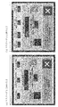
- FIG. 7 shows an answer screen presented to the subject.
- the answer screen when the masker has one sound source is shown in FIG. 7A
- the answer screen when the masker has two sound sources is shown in FIG. 7B.
- the direction of the masker the sound pressure level of the masker
- the direction of the masky the frequency of the masky
- the lamp that lights up while playing the masky the counter that indicates the number of times the masky is played
- the buttons that input whether or not the masky is detected are displayed. To be done.
- the test subject can perceive from which direction and in what size each sound source is presented and when.
- the reason for displaying the frequency of the masky is that the measurement is conducted while continuously changing the frequency of the masker (type of masker), so it is clarified which masky the subject is currently inputting, This is to prevent confusion of answers.
- the subject himself/herself notifies the PC that "the masky has been detected” by turning on the button for inputting the presence/absence of detection of the masky, and turns the button off to notify the PC that "the masky cannot be detected”. Let me know. Note that the initial value of the counter indicating the number of times the masky is reproduced is 0, and changes to 0, 1, 2, 3, 0,... In accordance with the number of times the masky is reproduced.
- the answer resets that is, the button for inputting the presence or absence of detection of the musky is turned off, and the musky shifts to the next sound pressure level or frequency.
- the subject must input the presence or absence of detection while this counter is displaying 1, 2, and 3.
- the listening experiment response program is Max ver. of Cycling '74. I am coding in 7.
- Math vers' MATLAB ver. Coding is done in R2018a.
- band noise and pure tone with a frequency (center frequency) of 400 Hz or 1000 Hz were prepared.
- these maskers will be described by the names from masker A (masker A) to masker D (masker D).
- the bandwidth of the band noise was determined so as to approximately match the bandwidth of the critical band. It is known that the noise component that contributes to the mask of a certain pure tone is limited to the component of a certain bandwidth in the band noise whose center frequency is the pure tone.
- the critical band is the band that contributes to such a pure tone mask.
- the subjects are two men in their twenties who are in good hearing (subject a, subject b).
- the masker any one of the above-mentioned sound sources from masker A to masker D was used.
- the sound pressure level of the masker was 60 dBSPL and 80 dBSPL.
- the azimuth of the masker was any one of the four azimuths of 0°, 45°, 90°, and 135°. That is, the masker orientation was targeted only at the four orientations on the left ear side.
- the threshold value is considered to be symmetric on the median plane, so the threshold value data for the remaining half circle, which cannot be obtained in this experiment, is symmetrical to the data obtained in this experiment.
- Results in. The musky uses one pure tone sound source, and its frequency and sound pressure level are as follows. Specifically, the frequency of the masky was determined to be dense at a frequency close to the frequency of the masker (center frequency). If the masker is a pure tone, it is considered that the masky cannot be perceived at any sound pressure level when the frequency of the masky is exactly the same as the frequency of the masker (400 Hz, 1000 Hz), so such frequency is not measured.
- the maximum level thereof is the sound pressure level of the masker
- the minimum level thereof is 20 dBSPL or 18 dBSPL.
- the maximum level was determined based on the expectation that when the sound pressure level of the musky was higher than that of the masker, the musky could be perceived completely.
- the minimum level was determined in consideration of the background noise level in the anechoic room, which is the experimental site, so that the measurement range was about 15 dB smaller than the background noise level.
- the direction of the maskey was 45° or 315°.
- the direction of the masky is 45°
- the directions of the masker and the masky match, so that the threshold value of the frequency masking that has been studied conventionally can be obtained as a result.
- the direction of the masky is 315°
- the masker and the masky exist in different directions, so that a masking threshold between stereo channels, that is, a spatial masking threshold value is obtained as a result.
- the direction of the musky was any one of eight directions from 0° to 315° at intervals of 45°.
- Table 3 shows the conditions when the number of placed maskers is two.
- the subject is only the subject a.
- the masker As for the masker, the masker A was arranged at an azimuth of 45° and the masker B was arranged at an azimuth of 315°. Muskey used a pure tone 1 sound source.
- As the frequency of the masky a condition in which the frequency (center frequency) of the masker is 400 Hz and the condition when it is 1000 Hz are combined. Since the placed maskers (masker A and masker B) are all band noises, even when the frequency of the masky is exactly the same as the center frequency of the masker (400 Hz, 1000 Hz), unlike the pure tone, there is a certain sound. It is considered that the masky can be perceived above the pressure level. Therefore, 400 Hz and 1000 Hz were also added to the measurement target.
- the maximum value of the sound pressure level of the Musky was set to be 9 dB higher than that in Table 2. This is because the sound pressure level of the sound to be heard rises by about 6 dB at the maximum due to the presence of two sound sources of the masker.
- the direction of the masky was 225°.
- the optimum values of ⁇ and ⁇ were calculated as follows. First, the mean squared error (MSE) between T spatial at certain ⁇ and ⁇ values and the maximum value of the threshold value at each direction of the masky obtained as an experimental result is defined as the type of masker (masker A ⁇ Masker D), calculation for all combinations of direction, sound pressure level. Next, the calculated mean square errors are summed for each type of masker. The above operation is repeated by changing the values of ⁇ and ⁇ , and the pair of ⁇ and ⁇ when the sum of the mean square errors for each type of masker is the minimum is the optimum value of ⁇ and ⁇ . ..
- the mean square error MSE(j) in the azimuth of the j-th masker is calculated by the following equation (6).
- T spatial (i) is the azimuth [deg. ]
- T measured (i) is the azimuth [deg. ]
- L masker azimuth represents the masky threshold value [dBSPL] in the direction in which the masker exists. This is because T spatial are representative of a attenuation threshold from existing orientation of the masker has a role of adjusting the offset between the T spatial and T Measured.
- N is the number of entries of T spatial and T measured (the total number of directions of the Muskie).
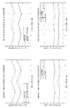
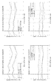
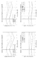
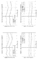
- FIGS. 8 to 11 show the values obtained by fitting T spatial to the actual values of the masky threshold values using the values in Table 5, respectively.
- the graph on the upper left of each figure shows the result for masker A
- the graph on the upper right shows the result for masker B
- the graph on the lower left shows the result for masker C
- the graph at the lower right shows the result for masker D.
- the horizontal axis of each graph is the direction of the masky
- the vertical axis is the sound pressure level.
- the direction corresponding to the direction of the masker is shown by the vertical dotted line.
- the black solid line represents the measured value of the masky threshold when the masker sound pressure level is 80 dBSPL
- the gray solid line represents the measured value of the masky threshold when the masker sound pressure level is 60 dBSPL.
- the red broken line represents the one fitted to the red solid line using the function T spatial
- the gray broken line represents the one fitted to the gray solid line using the function T spatial .
- Each broken line is the output of the function T spatial plus the offset L masker azimuth . It can be seen from FIGS. 8 to 11 that each of the graphs generally fits the measured value. However, for example, as shown in the upper left graph of FIG. 8 and the upper left graph of FIG.
- the values of ⁇ and ⁇ are obtained by brute force, but the value of ⁇ may be determined based on an index for discriminating the tonality (tone property, noise property) of the masker. it can.
- an index for determining the tonality of the masker there are, for example, autocorrelation and Spectral Flatness Measure (SFM). By using these indexes, ⁇ can be parametrically determined and fitted.
- a weighting threshold of 15 dB is added to the masking threshold value of the own channel signal exerted on the own channel as the masking threshold value of the own channel signal exerted on the other channel.
- the masky threshold rises in the direction symmetrical to the masker compared to the surrounding direction, and is more remarkable as the center frequency of the masker is lower.
- the masker is a pure tone, the change in the threshold value depending on the direction of the masky is flat.
- the sum of the masking threshold of the signal of the same direction as the masker and the masking threshold of the signal of other directions on the linear scale is added to the signal of its own direction. It may be used as a masking threshold in consideration of signals in other directions.
- the threshold value is highest when the masky position is 0°.
- the threshold value started to increase from 135°, and at 180°, the threshold value increased to almost the same level as the case of 0°. That is, the masking threshold value by the masker has a substantially symmetrical relationship before and after the listener.
- the threshold was highest when the masky position was 45°.
- the threshold dropped. It seemed that it would drop further at 135°, but contrary to expectations, the threshold increased and approached the threshold at 45°.
- the threshold decreased at 180° and further decreased at 225°.
- the masking thresholds have a substantially symmetrical relationship before and after the listener. That is, it was line-symmetric with respect to the line connecting 90° to 270°. The same tendency was observed when the masker was 90° and the masker was 135°.
- the masking threshold of the own channel and the masking threshold of the other channel are -15 dB.
- the weighted items are summed on a linear scale.
- an arbitrary periodic function with a period of 360° and a phase function that is phase-shifted so as to be linearly symmetric at 90° and 270° are used to change the change of the peak value of the Muskie threshold depending on the direction.
- Model. Using the modeled function, the masking threshold of each channel is weighted and then summed on a linear scale. That is, the masking threshold can be calculated by the above-mentioned formula (1). By calculating the masking threshold value based on this, the number of bits required for signal transmission can be reduced.
- the bio-sequence analysis method of the present invention can provide an acoustic signal coding method with a bit rate suppressed more than before by utilizing the spatial masking effect of auditory sense, and can be used industrially.
Landscapes
- Engineering & Computer Science (AREA)
- Physics & Mathematics (AREA)
- Signal Processing (AREA)
- Acoustics & Sound (AREA)
- Mathematical Physics (AREA)
- Computational Linguistics (AREA)
- Health & Medical Sciences (AREA)
- Audiology, Speech & Language Pathology (AREA)
- Human Computer Interaction (AREA)
- Multimedia (AREA)
- Stereophonic System (AREA)
- Compression, Expansion, Code Conversion, And Decoders (AREA)
Abstract
L'invention concerne un procédé de codage de signal acoustique capable de coder même des signaux acoustiques qui ont de nombreux canaux à un débit binaire suffisant. Le procédé de codage de signal acoustique est mis en oeuvre par un dispositif de codage 1, et code un signal acoustique multicanal. Tout d'abord, un seuil de masquage correspondant à l'effet de masquage auditif spatial est calculé. Ensuite, la quantité d'informations à attribuer pour chaque canal du signal acoustique multicanal est déterminée à l'aide du seuil de masquage calculé. Ensuite, le signal acoustique multicanal est codé à l'aide des quantités d'informations respectivement attribuées. Ainsi, il est possible de coder même des signaux acoustiques multicanaux à un débit binaire suffisant.
Priority Applications (4)
| Application Number | Priority Date | Filing Date | Title |
|---|---|---|---|
| EP20759801.2A EP3929918A4 (fr) | 2019-02-19 | 2020-02-18 | Procédé de codage de signal acoustique, procédé de décodage de signal acoustique, programme, dispositif de codage, système acoustique et dispositif de complexation |
| CN202080015479.XA CN113574596B (zh) | 2019-02-19 | 2020-02-18 | 音频信号编码方法、音频信号解码方法、程序、编码装置、音频系统及解码装置 |
| US17/432,098 US12143799B2 (en) | 2019-02-19 | 2020-02-18 | Acoustic signal encoding method, acoustic signal decoding method, program, encoding device, acoustic system, and decoding device |
| JP2021502010A JP7232546B2 (ja) | 2019-02-19 | 2020-02-18 | 音響信号符号化方法、音響信号復号化方法、プログラム、符号化装置、音響システム、及び復号化装置 |
Applications Claiming Priority (2)
| Application Number | Priority Date | Filing Date | Title |
|---|---|---|---|
| JP2019-027035 | 2019-02-19 | ||
| JP2019027035 | 2019-02-19 |
Publications (1)
| Publication Number | Publication Date |
|---|---|
| WO2020171049A1 true WO2020171049A1 (fr) | 2020-08-27 |
Family
ID=72144598
Family Applications (1)
| Application Number | Title | Priority Date | Filing Date |
|---|---|---|---|
| PCT/JP2020/006211 Ceased WO2020171049A1 (fr) | 2019-02-19 | 2020-02-18 | Procédé de codage de signal acoustique, procédé de décodage de signal acoustique, programme, dispositif de codage, système acoustique et dispositif de complexation |
Country Status (5)
| Country | Link |
|---|---|
| US (1) | US12143799B2 (fr) |
| EP (1) | EP3929918A4 (fr) |
| JP (1) | JP7232546B2 (fr) |
| CN (1) | CN113574596B (fr) |
| WO (1) | WO2020171049A1 (fr) |
Cited By (3)
| Publication number | Priority date | Publication date | Assignee | Title |
|---|---|---|---|---|
| JPWO2023286698A1 (fr) * | 2021-07-12 | 2023-01-19 | ||
| WO2024024468A1 (fr) * | 2022-07-25 | 2024-02-01 | ソニーグループ株式会社 | Dispositif et procédé de traitement d'informations, dispositif de codage, dispositif de lecture audio et programme |
| WO2025094886A1 (fr) * | 2023-11-02 | 2025-05-08 | ソニーグループ株式会社 | Dispositif et procédé de traitement d'informations |
Families Citing this family (6)
| Publication number | Priority date | Publication date | Assignee | Title |
|---|---|---|---|---|
| JP7427531B2 (ja) * | 2020-06-04 | 2024-02-05 | フォルシアクラリオン・エレクトロニクス株式会社 | 音響信号処理装置及び音響信号処理プログラム |
| CN115331692B (zh) * | 2022-03-22 | 2025-12-26 | 钉钉(中国)信息技术有限公司 | 一种降噪方法、电子设备及存储介质 |
| CN115602180A (zh) * | 2022-10-19 | 2023-01-13 | 东莞凯韵科技有限公司(Cn) | 一种基于高通芯片的自定义解码方法 |
| WO2025015478A1 (fr) * | 2023-07-14 | 2025-01-23 | 北京小米移动软件有限公司 | Procédé de traitement de signal et appareil associé |
| CN117716425A (zh) * | 2023-10-18 | 2024-03-15 | 北京小米移动软件有限公司 | 音频信号的处理方法、装置、音频设备及存储介质 |
| US20260039998A1 (en) * | 2024-08-05 | 2026-02-05 | Cisco Technology, Inc. | Activation of gooseneck microphone in integrated gooseneck/table microphone device |
Citations (5)
| Publication number | Priority date | Publication date | Assignee | Title |
|---|---|---|---|---|
| JP2014016625A (ja) * | 2008-01-04 | 2014-01-30 | Dolby International Ab | オーディオコーディングシステム、オーディオデコーダ、オーディオコーディング方法及びオーディオデコーディング方法 |
| JP2015531078A (ja) * | 2012-07-31 | 2015-10-29 | インテレクチュアル ディスカバリー シーオー エルティディIntellectual Discovery Co.,Ltd. | オーディオ信号処理方法および装置 |
| JP2016518788A (ja) * | 2013-04-29 | 2016-06-23 | ドルビー ラボラトリーズ ライセンシング コーポレイション | 動的閾値を用いた周波数帯域圧縮 |
| JP2016524726A (ja) * | 2013-05-28 | 2016-08-18 | クゥアルコム・インコーポレイテッドQualcomm Incorporated | 球面調和係数に対して空間マスキングを実行すること |
| JP2016224472A (ja) * | 2010-12-21 | 2016-12-28 | ドルビー・インターナショナル・アーベー | 二次元または三次元音場のアンビソニックス表現の一連のフレームをエンコードおよびデコードする方法および装置 |
Family Cites Families (13)
| Publication number | Priority date | Publication date | Assignee | Title |
|---|---|---|---|---|
| JP3446216B2 (ja) | 1992-03-06 | 2003-09-16 | ソニー株式会社 | 音声信号処理方法 |
| JPH10107642A (ja) * | 1996-06-14 | 1998-04-24 | Texas Instr Inc <Ti> | デジタルオーディオ符号化信号におけるマスキングしきい値を計算する方法 |
| US7333930B2 (en) * | 2003-03-14 | 2008-02-19 | Agere Systems Inc. | Tonal analysis for perceptual audio coding using a compressed spectral representation |
| CN1677490A (zh) * | 2004-04-01 | 2005-10-05 | 北京宫羽数字技术有限责任公司 | 一种增强音频编解码装置及方法 |
| US8332216B2 (en) * | 2006-01-12 | 2012-12-11 | Stmicroelectronics Asia Pacific Pte., Ltd. | System and method for low power stereo perceptual audio coding using adaptive masking threshold |
| WO2009067741A1 (fr) * | 2007-11-27 | 2009-06-04 | Acouity Pty Ltd | Compression de la bande passante de représentations paramétriques du champ acoustique pour transmission et mémorisation |
| US8219409B2 (en) * | 2008-03-31 | 2012-07-10 | Ecole Polytechnique Federale De Lausanne | Audio wave field encoding |
| CN101847413B (zh) * | 2010-04-09 | 2011-11-16 | 北京航空航天大学 | 一种使用新型心理声学模型和快速比特分配实现数字音频编码的方法 |
| CN102737635B (zh) * | 2011-04-08 | 2014-04-30 | 华为终端有限公司 | 一种音频编码方法以及音频编码设备 |
| US9466305B2 (en) * | 2013-05-29 | 2016-10-11 | Qualcomm Incorporated | Performing positional analysis to code spherical harmonic coefficients |
| DE102013217367A1 (de) * | 2013-05-31 | 2014-12-04 | Fraunhofer-Gesellschaft zur Förderung der angewandten Forschung e.V. | Vorrichtung und verfahren zur raumselektiven audiowiedergabe |
| EP3373604B1 (fr) * | 2017-03-08 | 2021-09-01 | Fraunhofer-Gesellschaft zur Förderung der angewandten Forschung e.V. | Appareil et procédé pour fournir une mesure de spatialité associée à un flux audio |
| US10075802B1 (en) * | 2017-08-08 | 2018-09-11 | Qualcomm Incorporated | Bitrate allocation for higher order ambisonic audio data |
-
2020
- 2020-02-18 WO PCT/JP2020/006211 patent/WO2020171049A1/fr not_active Ceased
- 2020-02-18 US US17/432,098 patent/US12143799B2/en active Active
- 2020-02-18 CN CN202080015479.XA patent/CN113574596B/zh active Active
- 2020-02-18 EP EP20759801.2A patent/EP3929918A4/fr active Pending
- 2020-02-18 JP JP2021502010A patent/JP7232546B2/ja active Active
Patent Citations (5)
| Publication number | Priority date | Publication date | Assignee | Title |
|---|---|---|---|---|
| JP2014016625A (ja) * | 2008-01-04 | 2014-01-30 | Dolby International Ab | オーディオコーディングシステム、オーディオデコーダ、オーディオコーディング方法及びオーディオデコーディング方法 |
| JP2016224472A (ja) * | 2010-12-21 | 2016-12-28 | ドルビー・インターナショナル・アーベー | 二次元または三次元音場のアンビソニックス表現の一連のフレームをエンコードおよびデコードする方法および装置 |
| JP2015531078A (ja) * | 2012-07-31 | 2015-10-29 | インテレクチュアル ディスカバリー シーオー エルティディIntellectual Discovery Co.,Ltd. | オーディオ信号処理方法および装置 |
| JP2016518788A (ja) * | 2013-04-29 | 2016-06-23 | ドルビー ラボラトリーズ ライセンシング コーポレイション | 動的閾値を用いた周波数帯域圧縮 |
| JP2016524726A (ja) * | 2013-05-28 | 2016-08-18 | クゥアルコム・インコーポレイテッドQualcomm Incorporated | 球面調和係数に対して空間マスキングを実行すること |
Non-Patent Citations (3)
| Title |
|---|
| ANDREAS SPANIAS ET AL.: "Audio Signal Processing and Coding", 2007, WILEY-INTERSCIENCE, JOHN WILEY & SONS, INC. |
| KODAI KATO, MASAYUKI NISHIGUCHI, KANJI WATANABE, SHOUICHI TAKANE, KOJI ABE: "Study on 3D audio coding based on spatial auditory masking", IEICE TECHNICAL REPORT, vol. 118, no. 497, 7 March 2019 (2019-03-07), pages 271 - 278, XP009530393 * |
| See also references of EP3929918A4 |
Cited By (5)
| Publication number | Priority date | Publication date | Assignee | Title |
|---|---|---|---|---|
| JPWO2023286698A1 (fr) * | 2021-07-12 | 2023-01-19 | ||
| WO2023286698A1 (fr) * | 2021-07-12 | 2023-01-19 | ソニーグループ株式会社 | Dispositif et procédé de codage, dispositif et procédé de décodage et programme |
| JP7827065B2 (ja) | 2021-07-12 | 2026-03-10 | ソニーグループ株式会社 | 符号化装置および方法、復号装置および方法、並びにプログラム |
| WO2024024468A1 (fr) * | 2022-07-25 | 2024-02-01 | ソニーグループ株式会社 | Dispositif et procédé de traitement d'informations, dispositif de codage, dispositif de lecture audio et programme |
| WO2025094886A1 (fr) * | 2023-11-02 | 2025-05-08 | ソニーグループ株式会社 | Dispositif et procédé de traitement d'informations |
Also Published As
| Publication number | Publication date |
|---|---|
| JPWO2020171049A1 (ja) | 2021-11-25 |
| JP7232546B2 (ja) | 2023-03-03 |
| EP3929918A1 (fr) | 2021-12-29 |
| CN113574596B (zh) | 2024-07-05 |
| EP3929918A4 (fr) | 2023-05-10 |
| US12143799B2 (en) | 2024-11-12 |
| US20230136085A1 (en) | 2023-05-04 |
| CN113574596A (zh) | 2021-10-29 |
Similar Documents
| Publication | Publication Date | Title |
|---|---|---|
| JP7232546B2 (ja) | 音響信号符号化方法、音響信号復号化方法、プログラム、符号化装置、音響システム、及び復号化装置 | |
| US10685638B2 (en) | Audio scene apparatus | |
| US20230413004A1 (en) | System and method for providing a spatialized soundfield | |
| KR20180108766A (ko) | 증강 현실 헤드폰 환경 렌더링 | |
| JP2020506639A (ja) | オーディオ信号処理方法及び装置 | |
| US20220369061A1 (en) | Spatial Audio Representation and Rendering | |
| Xie | Spatial sound: Principles and applications | |
| CN120457708A (zh) | 使用特定直达声处理的音频信号处理器、音频信号处理方法及计算机程序 | |
| Hládek et al. | Communication conditions in virtual acoustic scenes in an underground station | |
| WO2021261385A1 (fr) | Dispositif de reproduction acoustique, dispositif de casque antibruit, procédé de reproduction acoustique, et programme de reproduction acoustique | |
| CN115376527B (zh) | 三维音频信号编码方法、装置和编码器 | |
| JP2022128177A (ja) | 音声生成装置、音声再生装置、音声再生方法、及び音声信号処理プログラム | |
| Marschall | Capturing and reproducing realistic acoustic scenes for hearing research | |
| CN121925867A (zh) | 音响处理装置、阈值确定装置及音响处理方法 | |
| Urbanietz et al. | Binaural Rendering for Sound Navigation and Orientation | |
| WO2025075149A1 (fr) | Procédé de traitement de signal audio, programme informatique et dispositif de traitement de signal audio | |
| WO2024084999A1 (fr) | Dispositif de traitement audio et procédé de traitement audio | |
| Pawlak | Parametric Sound Field Auralization of Small Room Acoustics for Perceptual Research on Room Reflections | |
| Sunder et al. | Modeling distance-dependent individual head-related transfer functions in the horizontal plane using frontal projection headphones | |
| WO2025075147A1 (fr) | Procédé de traitement de signal audio, programme informatique et dispositif de traitement de signal audio | |
| Lacqua | Physical Acoustical Validation of the Audio Space Lab at the Polytechnic of Turin | |
| WO2025075136A1 (fr) | Procédé de traitement de signal audio, programme informatique, et dispositif de traitement de signal audio | |
| Pulkki | An Introduction to Sound, Hearing and Perception | |
| WO2024084998A1 (fr) | Dispositif de traitement audio, et procédé de traitement audio | |
| WO2025075135A1 (fr) | Procédé de traitement de signal audio, programme informatique et dispositif de traitement de signal audio |
Legal Events
| Date | Code | Title | Description |
|---|---|---|---|
| 121 | Ep: the epo has been informed by wipo that ep was designated in this application |
Ref document number: 20759801 Country of ref document: EP Kind code of ref document: A1 |
|
| ENP | Entry into the national phase |
Ref document number: 2021502010 Country of ref document: JP Kind code of ref document: A |
|
| NENP | Non-entry into the national phase |
Ref country code: DE |
|
| ENP | Entry into the national phase |
Ref document number: 2020759801 Country of ref document: EP Effective date: 20210920 |