WO2020171114A1 - Procédé de production de film, dispositif de production de film et procédé de production de feuille d'électrode - Google Patents
Procédé de production de film, dispositif de production de film et procédé de production de feuille d'électrode Download PDFInfo
- Publication number
- WO2020171114A1 WO2020171114A1 PCT/JP2020/006465 JP2020006465W WO2020171114A1 WO 2020171114 A1 WO2020171114 A1 WO 2020171114A1 JP 2020006465 W JP2020006465 W JP 2020006465W WO 2020171114 A1 WO2020171114 A1 WO 2020171114A1
- Authority
- WO
- WIPO (PCT)
- Prior art keywords
- metal foil
- contact
- film forming
- gas
- metal
- Prior art date
- Legal status (The legal status is an assumption and is not a legal conclusion. Google has not performed a legal analysis and makes no representation as to the accuracy of the status listed.)
- Ceased
Links
Images








Classifications
-
- C—CHEMISTRY; METALLURGY
- C23—COATING METALLIC MATERIAL; COATING MATERIAL WITH METALLIC MATERIAL; CHEMICAL SURFACE TREATMENT; DIFFUSION TREATMENT OF METALLIC MATERIAL; COATING BY VACUUM EVAPORATION, BY SPUTTERING, BY ION IMPLANTATION OR BY CHEMICAL VAPOUR DEPOSITION, IN GENERAL; INHIBITING CORROSION OF METALLIC MATERIAL OR INCRUSTATION IN GENERAL
- C23C—COATING METALLIC MATERIAL; COATING MATERIAL WITH METALLIC MATERIAL; SURFACE TREATMENT OF METALLIC MATERIAL BY DIFFUSION INTO THE SURFACE, BY CHEMICAL CONVERSION OR SUBSTITUTION; COATING BY VACUUM EVAPORATION, BY SPUTTERING, BY ION IMPLANTATION OR BY CHEMICAL VAPOUR DEPOSITION, IN GENERAL
- C23C16/00—Chemical coating by decomposition of gaseous compounds, without leaving reaction products of surface material in the coating, i.e. chemical vapour deposition [CVD] processes
- C23C16/44—Chemical coating by decomposition of gaseous compounds, without leaving reaction products of surface material in the coating, i.e. chemical vapour deposition [CVD] processes characterised by the method of coating
- C23C16/48—Chemical coating by decomposition of gaseous compounds, without leaving reaction products of surface material in the coating, i.e. chemical vapour deposition [CVD] processes characterised by the method of coating by irradiation, e.g. photolysis, radiolysis, particle radiation
- C23C16/481—Chemical coating by decomposition of gaseous compounds, without leaving reaction products of surface material in the coating, i.e. chemical vapour deposition [CVD] processes characterised by the method of coating by irradiation, e.g. photolysis, radiolysis, particle radiation by radiant heating of the substrate
-
- C—CHEMISTRY; METALLURGY
- C23—COATING METALLIC MATERIAL; COATING MATERIAL WITH METALLIC MATERIAL; CHEMICAL SURFACE TREATMENT; DIFFUSION TREATMENT OF METALLIC MATERIAL; COATING BY VACUUM EVAPORATION, BY SPUTTERING, BY ION IMPLANTATION OR BY CHEMICAL VAPOUR DEPOSITION, IN GENERAL; INHIBITING CORROSION OF METALLIC MATERIAL OR INCRUSTATION IN GENERAL
- C23C—COATING METALLIC MATERIAL; COATING MATERIAL WITH METALLIC MATERIAL; SURFACE TREATMENT OF METALLIC MATERIAL BY DIFFUSION INTO THE SURFACE, BY CHEMICAL CONVERSION OR SUBSTITUTION; COATING BY VACUUM EVAPORATION, BY SPUTTERING, BY ION IMPLANTATION OR BY CHEMICAL VAPOUR DEPOSITION, IN GENERAL
- C23C16/00—Chemical coating by decomposition of gaseous compounds, without leaving reaction products of surface material in the coating, i.e. chemical vapour deposition [CVD] processes
- C23C16/02—Pretreatment of the material to be coated
-
- C—CHEMISTRY; METALLURGY
- C23—COATING METALLIC MATERIAL; COATING MATERIAL WITH METALLIC MATERIAL; CHEMICAL SURFACE TREATMENT; DIFFUSION TREATMENT OF METALLIC MATERIAL; COATING BY VACUUM EVAPORATION, BY SPUTTERING, BY ION IMPLANTATION OR BY CHEMICAL VAPOUR DEPOSITION, IN GENERAL; INHIBITING CORROSION OF METALLIC MATERIAL OR INCRUSTATION IN GENERAL
- C23C—COATING METALLIC MATERIAL; COATING MATERIAL WITH METALLIC MATERIAL; SURFACE TREATMENT OF METALLIC MATERIAL BY DIFFUSION INTO THE SURFACE, BY CHEMICAL CONVERSION OR SUBSTITUTION; COATING BY VACUUM EVAPORATION, BY SPUTTERING, BY ION IMPLANTATION OR BY CHEMICAL VAPOUR DEPOSITION, IN GENERAL
- C23C16/00—Chemical coating by decomposition of gaseous compounds, without leaving reaction products of surface material in the coating, i.e. chemical vapour deposition [CVD] processes
- C23C16/02—Pretreatment of the material to be coated
- C23C16/0209—Pretreatment of the material to be coated by heating
-
- C—CHEMISTRY; METALLURGY
- C23—COATING METALLIC MATERIAL; COATING MATERIAL WITH METALLIC MATERIAL; CHEMICAL SURFACE TREATMENT; DIFFUSION TREATMENT OF METALLIC MATERIAL; COATING BY VACUUM EVAPORATION, BY SPUTTERING, BY ION IMPLANTATION OR BY CHEMICAL VAPOUR DEPOSITION, IN GENERAL; INHIBITING CORROSION OF METALLIC MATERIAL OR INCRUSTATION IN GENERAL
- C23C—COATING METALLIC MATERIAL; COATING MATERIAL WITH METALLIC MATERIAL; SURFACE TREATMENT OF METALLIC MATERIAL BY DIFFUSION INTO THE SURFACE, BY CHEMICAL CONVERSION OR SUBSTITUTION; COATING BY VACUUM EVAPORATION, BY SPUTTERING, BY ION IMPLANTATION OR BY CHEMICAL VAPOUR DEPOSITION, IN GENERAL
- C23C16/00—Chemical coating by decomposition of gaseous compounds, without leaving reaction products of surface material in the coating, i.e. chemical vapour deposition [CVD] processes
- C23C16/02—Pretreatment of the material to be coated
- C23C16/0254—Physical treatment to alter the texture of the surface, e.g. scratching or polishing
-
- C—CHEMISTRY; METALLURGY
- C23—COATING METALLIC MATERIAL; COATING MATERIAL WITH METALLIC MATERIAL; CHEMICAL SURFACE TREATMENT; DIFFUSION TREATMENT OF METALLIC MATERIAL; COATING BY VACUUM EVAPORATION, BY SPUTTERING, BY ION IMPLANTATION OR BY CHEMICAL VAPOUR DEPOSITION, IN GENERAL; INHIBITING CORROSION OF METALLIC MATERIAL OR INCRUSTATION IN GENERAL
- C23C—COATING METALLIC MATERIAL; COATING MATERIAL WITH METALLIC MATERIAL; SURFACE TREATMENT OF METALLIC MATERIAL BY DIFFUSION INTO THE SURFACE, BY CHEMICAL CONVERSION OR SUBSTITUTION; COATING BY VACUUM EVAPORATION, BY SPUTTERING, BY ION IMPLANTATION OR BY CHEMICAL VAPOUR DEPOSITION, IN GENERAL
- C23C16/00—Chemical coating by decomposition of gaseous compounds, without leaving reaction products of surface material in the coating, i.e. chemical vapour deposition [CVD] processes
- C23C16/22—Chemical coating by decomposition of gaseous compounds, without leaving reaction products of surface material in the coating, i.e. chemical vapour deposition [CVD] processes characterised by the deposition of inorganic material, other than metallic material
- C23C16/30—Deposition of compounds, mixtures or solid solutions, e.g. borides, carbides, nitrides
- C23C16/40—Oxides
-
- C—CHEMISTRY; METALLURGY
- C23—COATING METALLIC MATERIAL; COATING MATERIAL WITH METALLIC MATERIAL; CHEMICAL SURFACE TREATMENT; DIFFUSION TREATMENT OF METALLIC MATERIAL; COATING BY VACUUM EVAPORATION, BY SPUTTERING, BY ION IMPLANTATION OR BY CHEMICAL VAPOUR DEPOSITION, IN GENERAL; INHIBITING CORROSION OF METALLIC MATERIAL OR INCRUSTATION IN GENERAL
- C23C—COATING METALLIC MATERIAL; COATING MATERIAL WITH METALLIC MATERIAL; SURFACE TREATMENT OF METALLIC MATERIAL BY DIFFUSION INTO THE SURFACE, BY CHEMICAL CONVERSION OR SUBSTITUTION; COATING BY VACUUM EVAPORATION, BY SPUTTERING, BY ION IMPLANTATION OR BY CHEMICAL VAPOUR DEPOSITION, IN GENERAL
- C23C16/00—Chemical coating by decomposition of gaseous compounds, without leaving reaction products of surface material in the coating, i.e. chemical vapour deposition [CVD] processes
- C23C16/44—Chemical coating by decomposition of gaseous compounds, without leaving reaction products of surface material in the coating, i.e. chemical vapour deposition [CVD] processes characterised by the method of coating
- C23C16/4412—Details relating to the exhausts, e.g. pumps, filters, scrubbers, particle traps
-
- C—CHEMISTRY; METALLURGY
- C23—COATING METALLIC MATERIAL; COATING MATERIAL WITH METALLIC MATERIAL; CHEMICAL SURFACE TREATMENT; DIFFUSION TREATMENT OF METALLIC MATERIAL; COATING BY VACUUM EVAPORATION, BY SPUTTERING, BY ION IMPLANTATION OR BY CHEMICAL VAPOUR DEPOSITION, IN GENERAL; INHIBITING CORROSION OF METALLIC MATERIAL OR INCRUSTATION IN GENERAL
- C23C—COATING METALLIC MATERIAL; COATING MATERIAL WITH METALLIC MATERIAL; SURFACE TREATMENT OF METALLIC MATERIAL BY DIFFUSION INTO THE SURFACE, BY CHEMICAL CONVERSION OR SUBSTITUTION; COATING BY VACUUM EVAPORATION, BY SPUTTERING, BY ION IMPLANTATION OR BY CHEMICAL VAPOUR DEPOSITION, IN GENERAL
- C23C16/00—Chemical coating by decomposition of gaseous compounds, without leaving reaction products of surface material in the coating, i.e. chemical vapour deposition [CVD] processes
- C23C16/44—Chemical coating by decomposition of gaseous compounds, without leaving reaction products of surface material in the coating, i.e. chemical vapour deposition [CVD] processes characterised by the method of coating
- C23C16/455—Chemical coating by decomposition of gaseous compounds, without leaving reaction products of surface material in the coating, i.e. chemical vapour deposition [CVD] processes characterised by the method of coating characterised by the method used for introducing gases into reaction chamber or for modifying gas flows in reaction chamber
- C23C16/45523—Pulsed gas flow or change of composition over time
- C23C16/45525—Atomic layer deposition [ALD]
-
- C—CHEMISTRY; METALLURGY
- C23—COATING METALLIC MATERIAL; COATING MATERIAL WITH METALLIC MATERIAL; CHEMICAL SURFACE TREATMENT; DIFFUSION TREATMENT OF METALLIC MATERIAL; COATING BY VACUUM EVAPORATION, BY SPUTTERING, BY ION IMPLANTATION OR BY CHEMICAL VAPOUR DEPOSITION, IN GENERAL; INHIBITING CORROSION OF METALLIC MATERIAL OR INCRUSTATION IN GENERAL
- C23C—COATING METALLIC MATERIAL; COATING MATERIAL WITH METALLIC MATERIAL; SURFACE TREATMENT OF METALLIC MATERIAL BY DIFFUSION INTO THE SURFACE, BY CHEMICAL CONVERSION OR SUBSTITUTION; COATING BY VACUUM EVAPORATION, BY SPUTTERING, BY ION IMPLANTATION OR BY CHEMICAL VAPOUR DEPOSITION, IN GENERAL
- C23C16/00—Chemical coating by decomposition of gaseous compounds, without leaving reaction products of surface material in the coating, i.e. chemical vapour deposition [CVD] processes
- C23C16/44—Chemical coating by decomposition of gaseous compounds, without leaving reaction products of surface material in the coating, i.e. chemical vapour deposition [CVD] processes characterised by the method of coating
- C23C16/455—Chemical coating by decomposition of gaseous compounds, without leaving reaction products of surface material in the coating, i.e. chemical vapour deposition [CVD] processes characterised by the method of coating characterised by the method used for introducing gases into reaction chamber or for modifying gas flows in reaction chamber
- C23C16/45523—Pulsed gas flow or change of composition over time
- C23C16/45525—Atomic layer deposition [ALD]
- C23C16/45544—Atomic layer deposition [ALD] characterized by the apparatus
-
- C—CHEMISTRY; METALLURGY
- C23—COATING METALLIC MATERIAL; COATING MATERIAL WITH METALLIC MATERIAL; CHEMICAL SURFACE TREATMENT; DIFFUSION TREATMENT OF METALLIC MATERIAL; COATING BY VACUUM EVAPORATION, BY SPUTTERING, BY ION IMPLANTATION OR BY CHEMICAL VAPOUR DEPOSITION, IN GENERAL; INHIBITING CORROSION OF METALLIC MATERIAL OR INCRUSTATION IN GENERAL
- C23C—COATING METALLIC MATERIAL; COATING MATERIAL WITH METALLIC MATERIAL; SURFACE TREATMENT OF METALLIC MATERIAL BY DIFFUSION INTO THE SURFACE, BY CHEMICAL CONVERSION OR SUBSTITUTION; COATING BY VACUUM EVAPORATION, BY SPUTTERING, BY ION IMPLANTATION OR BY CHEMICAL VAPOUR DEPOSITION, IN GENERAL
- C23C16/00—Chemical coating by decomposition of gaseous compounds, without leaving reaction products of surface material in the coating, i.e. chemical vapour deposition [CVD] processes
- C23C16/44—Chemical coating by decomposition of gaseous compounds, without leaving reaction products of surface material in the coating, i.e. chemical vapour deposition [CVD] processes characterised by the method of coating
- C23C16/455—Chemical coating by decomposition of gaseous compounds, without leaving reaction products of surface material in the coating, i.e. chemical vapour deposition [CVD] processes characterised by the method of coating characterised by the method used for introducing gases into reaction chamber or for modifying gas flows in reaction chamber
- C23C16/45597—Reactive back side gas
-
- C—CHEMISTRY; METALLURGY
- C23—COATING METALLIC MATERIAL; COATING MATERIAL WITH METALLIC MATERIAL; CHEMICAL SURFACE TREATMENT; DIFFUSION TREATMENT OF METALLIC MATERIAL; COATING BY VACUUM EVAPORATION, BY SPUTTERING, BY ION IMPLANTATION OR BY CHEMICAL VAPOUR DEPOSITION, IN GENERAL; INHIBITING CORROSION OF METALLIC MATERIAL OR INCRUSTATION IN GENERAL
- C23C—COATING METALLIC MATERIAL; COATING MATERIAL WITH METALLIC MATERIAL; SURFACE TREATMENT OF METALLIC MATERIAL BY DIFFUSION INTO THE SURFACE, BY CHEMICAL CONVERSION OR SUBSTITUTION; COATING BY VACUUM EVAPORATION, BY SPUTTERING, BY ION IMPLANTATION OR BY CHEMICAL VAPOUR DEPOSITION, IN GENERAL
- C23C16/00—Chemical coating by decomposition of gaseous compounds, without leaving reaction products of surface material in the coating, i.e. chemical vapour deposition [CVD] processes
- C23C16/44—Chemical coating by decomposition of gaseous compounds, without leaving reaction products of surface material in the coating, i.e. chemical vapour deposition [CVD] processes characterised by the method of coating
- C23C16/458—Chemical coating by decomposition of gaseous compounds, without leaving reaction products of surface material in the coating, i.e. chemical vapour deposition [CVD] processes characterised by the method of coating characterised by the method used for supporting substrates in the reaction chamber
- C23C16/4582—Rigid and flat substrates, e.g. plates or discs
- C23C16/4583—Rigid and flat substrates, e.g. plates or discs the substrate being supported substantially horizontally
- C23C16/4586—Elements in the interior of the support, e.g. electrodes, heating or cooling devices
-
- C—CHEMISTRY; METALLURGY
- C23—COATING METALLIC MATERIAL; COATING MATERIAL WITH METALLIC MATERIAL; CHEMICAL SURFACE TREATMENT; DIFFUSION TREATMENT OF METALLIC MATERIAL; COATING BY VACUUM EVAPORATION, BY SPUTTERING, BY ION IMPLANTATION OR BY CHEMICAL VAPOUR DEPOSITION, IN GENERAL; INHIBITING CORROSION OF METALLIC MATERIAL OR INCRUSTATION IN GENERAL
- C23C—COATING METALLIC MATERIAL; COATING MATERIAL WITH METALLIC MATERIAL; SURFACE TREATMENT OF METALLIC MATERIAL BY DIFFUSION INTO THE SURFACE, BY CHEMICAL CONVERSION OR SUBSTITUTION; COATING BY VACUUM EVAPORATION, BY SPUTTERING, BY ION IMPLANTATION OR BY CHEMICAL VAPOUR DEPOSITION, IN GENERAL
- C23C16/00—Chemical coating by decomposition of gaseous compounds, without leaving reaction products of surface material in the coating, i.e. chemical vapour deposition [CVD] processes
- C23C16/44—Chemical coating by decomposition of gaseous compounds, without leaving reaction products of surface material in the coating, i.e. chemical vapour deposition [CVD] processes characterised by the method of coating
- C23C16/54—Apparatus specially adapted for continuous coating
- C23C16/545—Apparatus specially adapted for continuous coating for coating elongated substrates
-
- H—ELECTRICITY
- H01—ELECTRIC ELEMENTS
- H01G—CAPACITORS; CAPACITORS, RECTIFIERS, DETECTORS, SWITCHING DEVICES, LIGHT-SENSITIVE OR TEMPERATURE-SENSITIVE DEVICES OF THE ELECTROLYTIC TYPE
- H01G13/00—Apparatus specially adapted for manufacturing capacitors; Processes specially adapted for manufacturing capacitors not provided for in groups H01G4/00 - H01G11/00
- H01G13/006—Apparatus or processes for applying terminals
-
- H—ELECTRICITY
- H01—ELECTRIC ELEMENTS
- H01G—CAPACITORS; CAPACITORS, RECTIFIERS, DETECTORS, SWITCHING DEVICES, LIGHT-SENSITIVE OR TEMPERATURE-SENSITIVE DEVICES OF THE ELECTROLYTIC TYPE
- H01G9/00—Electrolytic capacitors, rectifiers, detectors, switching devices, light-sensitive or temperature-sensitive devices; Processes of their manufacture
-
- H—ELECTRICITY
- H01—ELECTRIC ELEMENTS
- H01G—CAPACITORS; CAPACITORS, RECTIFIERS, DETECTORS, SWITCHING DEVICES, LIGHT-SENSITIVE OR TEMPERATURE-SENSITIVE DEVICES OF THE ELECTROLYTIC TYPE
- H01G9/00—Electrolytic capacitors, rectifiers, detectors, switching devices, light-sensitive or temperature-sensitive devices; Processes of their manufacture
- H01G9/0029—Processes of manufacture
- H01G9/0032—Processes of manufacture formation of the dielectric layer
-
- H—ELECTRICITY
- H01—ELECTRIC ELEMENTS
- H01G—CAPACITORS; CAPACITORS, RECTIFIERS, DETECTORS, SWITCHING DEVICES, LIGHT-SENSITIVE OR TEMPERATURE-SENSITIVE DEVICES OF THE ELECTROLYTIC TYPE
- H01G9/00—Electrolytic capacitors, rectifiers, detectors, switching devices, light-sensitive or temperature-sensitive devices; Processes of their manufacture
- H01G9/004—Details
- H01G9/04—Electrodes or formation of dielectric layers thereon
- H01G9/048—Electrodes or formation of dielectric layers thereon characterised by their structure
- H01G9/055—Etched foil electrodes
-
- H—ELECTRICITY
- H01—ELECTRIC ELEMENTS
- H01G—CAPACITORS; CAPACITORS, RECTIFIERS, DETECTORS, SWITCHING DEVICES, LIGHT-SENSITIVE OR TEMPERATURE-SENSITIVE DEVICES OF THE ELECTROLYTIC TYPE
- H01G9/00—Electrolytic capacitors, rectifiers, detectors, switching devices, light-sensitive or temperature-sensitive devices; Processes of their manufacture
- H01G9/004—Details
- H01G9/07—Dielectric layers
-
- H—ELECTRICITY
- H01—ELECTRIC ELEMENTS
- H01G—CAPACITORS; CAPACITORS, RECTIFIERS, DETECTORS, SWITCHING DEVICES, LIGHT-SENSITIVE OR TEMPERATURE-SENSITIVE DEVICES OF THE ELECTROLYTIC TYPE
- H01G13/00—Apparatus specially adapted for manufacturing capacitors; Processes specially adapted for manufacturing capacitors not provided for in groups H01G4/00 - H01G11/00
Definitions
- the present invention relates to a film forming method using an atomic layer deposition method, a film forming apparatus, and an electrode foil manufacturing method, and to a method and an apparatus for forming a layer containing a metal oxide (dielectric layer) on both surfaces of a metal foil.
- a metal oxide (dielectric) layer is formed on the surface of the metal foil used as the electrode foil of the electrolytic capacitor.
- Patent Document 1 teaches that a dielectric layer is formed on the main surface of a metal foil by an atomic layer deposition method (ALD method).
- the dielectric layer is usually formed on both main surfaces of the metal foil. From the viewpoint of productivity, it is required to efficiently form the dielectric layer on both main surfaces of the metal foil.
- WHEREIN The heating process which contacts a part of metal foil containing a 1st metal with one or more heating elements, and heats the said metal foil, and a part of said metal foil were supported.
- a second aspect of the present invention includes at least one chamber, a pressure control unit that controls the pressure in the chamber to a reduced pressure atmosphere, and a first supply port that supplies a first gas containing a second metal to the chamber.
- a second supply port for supplying a second gas containing an oxidant to the chamber, a first exhaust port for discharging the first gas from the chamber, and a second exhaust port for discharging the second gas from the chamber
- one or more heating elements that are disposed in the chamber and that heat the metal foil by contacting a portion of the metal foil that is a film-forming target, and the first gas and the second gas. Relates to a film forming apparatus which is supplied so as to contact both main surfaces of the metal foil.
- a third aspect of the present invention is a preparation step of preparing a metal foil containing a first metal, a roughening step of roughening both main surfaces of the metal foil, and the roughened metal foil.
- a step of heating the metal foil by bringing a part of the metal foil into contact with one or more heating elements, and a first metal containing a second metal on both sides of the metal foil with a part of the metal foil supported.
- WHEREIN The 1st contact process which contacts the 1st gas containing a 2nd metal on both surfaces of the metal foil containing a 1st metal, and the 2nd gas containing an oxidizing agent on the both surfaces of the said metal foil.
- the present invention relates to a method for forming a layer containing a metal oxide.
- a fifth aspect of the present invention is a preparation step of preparing a metal foil containing a first metal, a roughening step of roughening both main surfaces of the metal foil, and a roughened metal foil.
- a sixth aspect of the present invention is a first contact step of contacting both sides of a metal foil containing a first metal with a first gas containing a second metal, and a second gas containing an oxidizing agent on both sides of the metal foil. And a second contacting step of contacting the metal foil with an applying step of contacting a part of the metal foil with one or more power feeding bodies and applying a voltage to the metal foil in the presence of the second gas.
- the present invention relates to a method for forming a layer containing a metal oxide.
- a seventh aspect of the present invention is a preparatory step of preparing a metal foil containing a first metal, a roughening step of roughening both main surfaces of the metal foil, and a roughened metal foil.
- An eighth aspect of the present invention includes at least one chamber, a pressure control unit that controls the pressure in the chamber to a reduced pressure atmosphere, and a first supply port that supplies a first gas containing a second metal to the chamber.
- a second supply port for supplying a second gas containing an oxidant to the chamber, a first exhaust port for discharging the first gas from the chamber, and a second exhaust port for discharging the second gas from the chamber
- the second gas relates to a film forming apparatus that is supplied so as to contact both main surfaces of the metal foil.
- a heating step of heating a part of the metal foil by bringing a part of the metal foil containing the first metal into contact with one or more heating elements to support the part of the metal foil.
- an applying step of applying a metal oxide layer is an applying step of applying a metal oxide layer.
- the film-forming target on which the dielectric layer is formed is a metal foil.
- the metal foil has higher heat resistance, higher thermal conductivity and higher conductivity than a resin film or the like, and has a certain degree of rigidity.
- a layer containing a metal oxide (dielectric layer) is simultaneously formed on both main surfaces of the metal foil.
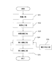
- the film forming method includes a heating step of heating a metal foil by bringing a part of the metal foil containing the first metal into contact with one or more heating elements, and a state in which a part of the metal foil is supported. Then, a first contact step of contacting a first gas containing a second metal with both surfaces of the metal foil, and a second gas containing an oxidant on both surfaces of the metal foil with a part of the metal foil being supported. And a second contacting step.
- the film forming method according to the first aspect is performed using the following film forming apparatus.
- the present embodiment includes this film forming apparatus. That is, the film forming apparatus according to the first aspect includes at least one chamber, a pressure control unit that controls the pressure in the chamber to a depressurized atmosphere, and a first supply port that supplies the chamber with a first gas containing a second metal.
- a second supply port for supplying a second gas containing an oxidant to the chamber; a first exhaust port for discharging the first gas from the chamber; a second exhaust port for discharging the second gas from the chamber;
- one or more heating elements for heating the metal foil by contacting a part of the metal foil which is a film formation target.
- the first gas and the second gas are supplied so as to contact both main surfaces of the metal foil.
- An electrode foil of an electrolytic capacitor can be manufactured using the film forming apparatus and/or the film forming method according to the first aspect.
- the present embodiment includes a method for manufacturing this electrode foil. That is, the manufacturing method of the electrode foil according to the first aspect includes a preparation step of preparing a metal foil containing the first metal, a roughening step of roughening both main surfaces of the metal foil, and a roughening step.
- a film forming method includes a first contact step of contacting both sides of a metal foil containing a first metal with a first gas containing a second metal, and a second gas containing an oxidant on both sides of the metal foil.
- An electrode foil of an electrolytic capacitor can be manufactured by using the film forming method according to the second aspect.
- the present embodiment includes a method for manufacturing this electrode foil. That is, the manufacturing method of the electrode foil according to the second aspect includes a preparation step of preparing a metal foil containing the first metal, a roughening step of roughening both main surfaces of the metal foil, and a roughening step.
- a first contact step of contacting both sides of the metal foil with a first gas containing a second metal a second contact step of contacting both sides of the metal foil with a second gas containing an oxidant, and a part of the metal foil.
- a first applying step of applying a voltage to the metal foil in the presence of the first gas by contacting with one or more first power feeding bodies.
- the film forming method includes a first contact step of contacting both sides of a metal foil containing a first metal with a first gas containing a second metal, and a second gas containing an oxidizing agent on both sides of the metal foil.
- the electrode foil of an electrolytic capacitor can be manufactured by using the film forming method according to the third aspect.
- the present embodiment includes a method for manufacturing this electrode foil. That is, the manufacturing method of the electrode foil according to the third aspect includes a preparation step of preparing a metal foil containing the first metal, a roughening step of roughening both main surfaces of the metal foil, and a roughening step.
- a first contact step of contacting both sides of the metal foil with a first gas containing a second metal a second contact step of contacting both sides of the metal foil with a second gas containing an oxidant, and a part of the metal foil.
- a second applying step of applying a voltage to the metal foil in the presence of the second gas by contacting the one or more second power feeding bodies.
- the film forming method according to the second aspect and the third aspect is performed using the following film forming apparatus.
- the present embodiment includes this film forming apparatus. That is, the film forming apparatus according to the second aspect and the third aspect supplies at least one chamber, a pressure control unit that controls the pressure inside the chamber to a reduced pressure atmosphere, and a first gas containing a second metal into the chamber.
- a mouth one or more power feeding bodies that contact a part of the metal foil that is the film-forming target, and a counter electrode that generates a voltage difference between the metal foil and the power feeding body.
- the first gas and the second gas are supplied so as to contact both main surfaces of the metal foil.
- a heating step of heating a metal foil by bringing a part of the metal foil containing the first metal into contact with one or more heating elements, and a state in which a part of the metal foil is supported Then, a first contacting step of contacting the first gas containing the second metal with both surfaces of the metal foil, and a second gas containing an oxidant on both surfaces of the metal foil with a part of the metal foil supported.
- the metal foil is heated.
- the heat accelerates the reaction between the molecule containing the second metal and/or the oxidizing agent and the surface of the metal foil. Therefore, a uniform dielectric layer is formed.
- the film forming method according to the first aspect includes a heating step of heating a metal foil.
- FIG. 1 is a flowchart showing the film forming method according to the first aspect.
- the metal foil contains the first metal.
- the type of the first metal is not particularly limited.
- the first metal may be a valve-action metal such as aluminum (Al), tantalum (Ta), or niobium (Nb) or an alloy containing a valve-action metal from the viewpoint of easy formation of the dielectric layer.
- the thickness of the metal foil is not particularly limited, but may be, for example, 10 ⁇ m or more and 300 ⁇ m or less, and may be 15 ⁇ m or more and 250 ⁇ m or less.
- the purity of the metal foil is not particularly limited. The purity of the metal foil may be, for example, 99% or more and 99.99% or less.
- the surface of the metal foil may be roughened. Further, another dielectric layer may be formed on the surface of the metal foil.
- the metal foil may have another dielectric layer formed inside the pits formed by roughening.
- the other dielectric film is formed by, for example, anodic oxidation.
- a surface modification treatment for modifying the surface of the metal foil may be performed before the first contact step, preferably before the heating step.
- a surface modification treatment is performed to remove impurities on the surface of the metal foil and modify the surface condition of the metal foil.
- the uniformity, adhesion, and denseness of the formed film, the effect of preventing diffusion of metal atoms in the metal foil, and the insulating property are improved, and the characteristics such as leakage current and capacitance are further improved.
- the withstand voltage of the obtained electrode foil is 200 V or less, further 50 V or less, the effect of the surface modification step is easily obtained.
- the surface modification treatment is not particularly limited, and examples thereof include plasma treatment and atmospheric pressure plasma treatment.
- the surface modification treatment may be performed in the atmosphere or under reduced pressure.
- the surface modification for example, hydroxyl groups are added to the surface of the metal foil, or impurities such as organic substances are decomposed or vaporized.
- Heating step (S112)
- the metal foil is brought into contact with the heating element. Since metal foils generally have high heat resistance, a method of heating by contact can be applied. Since atomic layer deposition (ALD) is performed in a reduced pressure atmosphere, heat propagation by convection cannot be expected so much. Therefore, the method of the present embodiment that can heat by utilizing heat conduction is suitable for the ALD method. A part of the metal foil comes into contact with the heating element. Since the metal foil has high thermal conductivity, the whole metal foil can be rapidly heated by bringing a part of the metal foil into contact with the heating element.
- ALD atomic layer deposition
- the metal foil When heating, the metal foil may be pressed toward the heating element by a pressing member arranged at a position corresponding to the heating element. As a result, the metal foil and the heating element are brought into closer contact with each other, and the metal foil is efficiently heated.
- the pressing member is brought into contact with a part of the metal foil, like the heating element.
- the pressing member may be a heating element. The heating efficiency is further improved by bringing the heating element into contact with both main surfaces of the metal foil.
- the heating temperature is not particularly limited and may be appropriately set according to the conditions of the method for forming the dielectric layer (atomic layer deposition method).
- the heating temperature is, for example, 80° C. or higher and 550° C. or lower.
- the heating temperature is preferably 90°C or higher and 525°C or lower.
- the heating temperature is in this range, the effect of heating is easily obtained, and the deformation of the metal foil is easily suppressed.
- stress is applied to the metal foil by a roller or the like, and pit deformation or plastic deformation easily occurs.
- the transportation becomes unstable and the film formation is likely to be uneven.
- the heating temperature is preferably 90°C or higher and 480°C or lower. When the heating temperature is within this range, the pit shape deformation and the plastic deformation can be further reduced.
- the second metal examples include Al, Ta, Nb, silicon (Si), titanium (Ti), zirconium (Zr), hafnium (Hf) and the like. These may be used alone or in combination of two or more. That is, the dielectric layer may include Al 2 O 3 , Ta 2 O 5 , Nb 2 O 5 , SiO 2 , TiO 2 , ZrO 2 , and HfO 2 alone or in combination of two or more. When the dielectric layer contains two or more kinds of oxides of the second metal, the oxides may be mixed or may be arranged in layers. Among them, the second metal is preferably a metal species different from the first metal contained in the metal foil.
- the oxide of the second metal preferably has a higher relative dielectric constant than the oxide of the first metal in that the capacity of the obtained electrolytic capacitor increases.
- the oxide of the second metal is preferably Ta 2 O 5, SiO 2, ZrO 2 , or HfO 2 in that the withstand voltage of the electrolytic capacitor is improved.
- the first gas contains a precursor (precursor) containing a second metal in a gas state.
- the first gas may include a plurality of types of precursors. Different types of precursors may be supplied to the chamber simultaneously or sequentially. Alternatively, the type of precursor contained in the first gas may be changed for each cycle.
- the precursor is an organometallic compound containing a second metal, which facilitates the chemical adsorption of the second metal to the target.
- various organometallic compounds conventionally used in the ALD method can be used.
- the precursor containing Ti e.g., bis (t-butylcyclopentadienyl) titanium (IV) dichloride (C 18 H 26 C l2 Ti ), tetrakis (dimethylamino) titanium (IV) ([(CH 3) 2 N] 4 Ti, TDMAT), tetrakis (diethylamino) titanium (IV) ([(C 2 H 5) 2 N] 4 Ti), tetrakis (ethylmethylamino) titanium (IV) (Ti [N ( C 2 H 5 )(CH 3 )] 4 ), titanium (IV) (diisopropoxide-bis(2,2,6,6-tetramethyl-3,5-heptanedionate (Ti[OCC(CH 3 ) 3 CHCOC( CH 3) 3] 2 (OC 3 H 7) 2), titanium tetrachloride (TiCl 4), titanium (IV) isopropoxide (Ti [OCH (CH 3) 2]
- Examples of the precursor containing Al include trimethylaluminum ((CH 3 ) 3 Al) and the like.
- the precursor containing Zr for example, bis (methyl - ⁇ 5- cyclopentadienyl) methoxymethyl zirconium (Zr (CH 3 C 5 H 4) 2 CH 3 OCH 3), tetrakis (dimethylamido) zirconium (IV) ( [(CH 3) 2 N] 4 Zr), tetrakis (ethylmethylamido) zirconium (IV) (Zr (NCH 3 C 2 H 5) 4), zirconium (IV) t-butoxide (Zr [OC (CH 3) 3 ] 4 ) and the like.
- Examples of the precursor containing Nb include niobium(V) ethoxide (Nb(OCH 2 CH 3 ) 5 and tris(diethylamido)(t-butylimido) niobium(V)(C 16 H 39 N 4 Nb). ..
- Examples of the precursor containing Si include N-sec-butyl(trimethylsilyl)amine (C 7 H 19 NSi), 1,3-diethyl-1,1,3,3-tetramethyldisilazane (C 8 H 23 NSi).
- tris(ethylmethylamide)(t-butylamido)tantalum (V) C 13 H 33 N 4 Ta
- tantalum (V) pentaethoxide Ta(OC 2 H 5 ) 5
- tris(diethylamido)(t-butylimido)tantalum V)((CH 3 ) 3 CNTa(N(C 2 H 5 ) 2 ) 3
- pentakis(dimethylamino)tantalum (V)(Ta(N(CH(CH 3 ) 2 ) 5 ) etc. are mentioned.
- Examples of the precursor containing Hf include hafnium tetrachloride (HfCl 4 ), tetrakisdimethylaminohafnium (Hf[N(CH 3 ) 2 ] 4 ) and tetrakisethylmethylaminohafnium (Hf[N(C 2 H 5 )( CH 3 )] 4 ), tetrakisdiethylaminohafnium (Hf[N(C 2 H 5 ) 2 ] 4 ), hafnium-t-butoxide (Hf[OC(CH 3 ) 3 ] 4 ), and the like.
- HfCl 4 hafnium tetrachloride
- HfCl 4 tetrakisdimethylaminohafnium
- Hf[N(C 2 H 5 )( CH 3 )] 4 tetrakisdiethylaminohafnium
- hafnium-t-butoxide H
- Second contact step After exhausting (purging) the first gas, the second gas is brought into contact with the metal foil. Also at this time, a part of the metal foil is supported. Therefore, the second gas can contact both surfaces of the metal foil. Molecules containing the second metal attached to both sides of the metal foil react with the oxidant contained in the second gas to generate an oxide of the second metal. As a result, the dielectric layers containing the oxide of the second metal are formed on both surfaces of the metal foil without performing the operation of replacing the upper and lower surfaces of the metal foil.
- the second gas contains an inert gas and an oxidant.
- the inert gas the inert gas conventionally used in the ALD method can be used.
- the inert gas is, for example, nitrogen or argon.
- the oxidizing agent As the oxidizing agent, the oxidizing agent conventionally used in the ALD method can be used.
- the oxidant include water, oxygen, ozone, hydrogen peroxide, and carbon dioxide.
- the oxidant may be supplied to the reaction chamber as plasma using the oxidant as a raw material.
- the order of each process is not particularly limited.
- the first gas is contacted with the metal foil, and then the second gas is contacted with the metal foil.
- the first contacting step may be performed while heating the metal foil.
- the second contacting step may be performed while heating the metal foil.
- the first contact step and the second contact step may be repeated multiple times. Specifically, the supply of the first gas (pulse) ⁇ the exhaust of the first gas (purge) ⁇ the supply of the second gas (pulse) ⁇ the exhaust of the second gas (purge) may be repeated in the chamber. The type of the first gas and/or the second gas may be changed for each cycle. After the dielectric layer made of the first gas and the second gas is formed, another dielectric layer made of the other first gas and the second gas may be further formed.
- the second metal is deposited on the surface of the target object in atomic layer units. Therefore, the thickness of the dielectric layer is controlled by the number of cycles including the first contact step and the second contact step as one cycle.
- the thickness of the dielectric layer is not particularly limited and may be, for example, 0.5 nm or more and 200 nm or less.
- the heating step and the first contact step and/or the second contact step are preferably performed in the same chamber space.
- the same chamber does not include the case where, for example, 80% or more of the walls connecting the two chambers are physically closed.
- the method for manufacturing an electrode foil according to the first aspect includes a heating step of heating a metal foil by bringing a part of the metal foil into contact with one or more heating elements.
- both the metal foil having a predetermined size and the elongated metal foil are film forming objects.
- the electrode foil manufactured by the above method is preferably used as an anode body of an electrolytic capacitor.
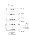
- FIG. 2 is a flowchart showing the method for manufacturing the electrode foil according to the first aspect.
- Preparation step (S11) A metal foil similar to that described in the film forming method according to the first aspect is prepared.
- the metal foil may have another dielectric layer formed inside the pit formed by roughening.
- the surface of the metal foil may be roughened before heating the metal foil. Due to the roughening, a plurality of pits are formed on the surface of the metal foil. By forming a dielectric layer even inside the pits in a later step, it can be expected that the capacitance will increase. On the other hand, if the surface of the metal foil is roughened in this way, it is usually difficult to form the dielectric layer even inside the pits by a method other than anodization. By performing the heat treatment as in this embodiment, it becomes easy to form a uniform dielectric layer even inside the pits.
- this step After forming the dielectric layer containing the oxide of the second metal and then performing anodic oxidation to form the third dielectric layer described later, it is preferable to perform this step.
- this step may be omitted.
- Roughening is performed, for example, by etching a metal foil.
- the etching treatment is preferably performed by an electrolytic etching method.
- the electrolytic etching is performed by passing a direct current or an alternating current through the metal foil.
- the electrolytic etching is performed, for example, in a hydrochloric acid aqueous solution.
- the hole diameter of the pit is not particularly limited.
- the hole diameter of the pit is preferably 50 nm or more and 2000 nm or less from the viewpoint of easily increasing the surface area. From the viewpoint of the contact between the metal foil and the heating element, the transport roll, or the like, it is preferable that the hole diameter of the pit is not too large.
- the hole diameter of the pit is more preferably 80 nm or more and 1300 nm or less.
- the pore diameter of the pit is the most frequent pore diameter of the pore distribution measured by, for example, a mercury porosimeter (hereinafter the same).
- the thickness of the etching layer formed by a plurality of pits is not particularly limited, and may be set appropriately according to the thickness of the metal foil.
- the thickness of the etching layer is preferably 5 ⁇ m or more, more preferably 15 ⁇ m or more, from the viewpoint of capacitance. When the thickness of the etching layer is in this range, the effect of heating is easily obtained.
- the thickness of the etching layer is preferably 100 ⁇ m or less, more preferably 80 ⁇ m or less.
- the thickness of the etching layer is the thickness of the etching layer formed on one main surface of the metal foil.
- the thickness of the etching layer is an average value at arbitrary 10 points in the SEM or TEM image of the cross section of the metal foil.
- the thickness of the dielectric layer is calculated in the same manner (hereinafter the same).
- FIG. 3 is a SEM image (300 times) of a cross section of the roughened metal foil according to the present embodiment.
- the region shown in light gray in the center is the core with lower porosity.
- the core is an unetched area of the metal foil.
- the area adjacent to the core and shown in dark gray is the etching layer.
- the etching layers are respectively formed on both main surface sides of the metal foil.
- the part shown in black outside the etching layer is the background.
- a surface modification treatment for modifying the surface of the metal foil may be performed before the first contact step, preferably before the heating step.
- the surface modification step is performed in the same manner as (i) the surface modification step in the film forming method according to the first aspect.
- the metal foil is heated in the same manner as (ii) the heating step in the film forming method according to the first aspect.
- the heating of the metal foil is performed by bringing the heating element into contact with part of the metal foil.
- the heating of the metal foil is preferably performed in the chamber to which the first gas is supplied. During heating, the inside of the chamber may be depressurized.
- First contact step (S15) and second contact step (S16) The first gas and the second gas are respectively brought into contact with both surfaces of the metal foil using the above film forming apparatus.
- Each contacting step is performed in the same manner as the (iii) first contacting step and the (iv) second contacting step in the film forming method according to the first aspect. Thereby, the dielectric layers containing the oxide of the second metal are formed on both surfaces of the metal foil.
- the metal foil may be formed.
- the third dielectric layer containing the oxide of the first metal forming the metal foil is formed between the metal foil and the dielectric layer. Therefore, as a whole dielectric layer, a layer having a uniform thickness without pinholes is easily formed.
- the method for forming the metal foil is not particularly limited.
- the chemical conversion is performed, for example, by immersing the metal foil in a chemical conversion liquid and applying a voltage (anodic oxidation).
- the film forming apparatus includes a heating element that is disposed in the chamber and that contacts a part of the metal foil that is a film forming object to heat the metal foil.
- the first gas and the second gas are supplied so as to contact both main surfaces of the metal foil.
- the heating element heats the metal foil by contacting a part of the metal foil which is a film formation target.
- the number of heating elements may be one or more, and may be two or more.
- the shape of the heating element is not particularly limited as long as it can contact the metal foil in a certain area.
- the heating element may be, for example, a stage that supports the metal foil, a transport roll, or a positioning member that positions the metal foil.
- the film forming apparatus includes at least one chamber.
- the film forming apparatus may include one chamber capable of supplying and exhausting the first gas and the second gas.
- the film forming apparatus may include a plurality of chambers capable of supplying and exhausting the first gas and the second gas.
- the same type of first gas may be supplied to the plurality of chambers, and the plurality of types of first gas containing different second metals may be supplied respectively.
- the same type of second gas may be supplied, and the plurality of types of second gas containing different oxidants may be supplied respectively.
- the heating element may be arranged in at least one of the plurality of chambers.
- the film forming apparatus may include a first chamber that can supply and exhaust the first gas, and a second chamber that can supply and exhaust the second gas.
- the heating element may be arranged in at least one of these chambers.
- the heating element is located in the first chamber.
- the film forming apparatus may include a plurality of the first chambers and/or the second chambers.
- the same type of first gas may be supplied to the plurality of first chambers, and the plurality of types of first gas containing different second metals may be supplied respectively.
- the plurality of second chambers the same type of second gas may be supplied, and the plurality of types of second gas containing different oxidants may be supplied respectively.
- the heating element may be arranged in at least one of the plurality of chambers.
- the heating element is arranged in at least one first chamber.
- the film forming apparatus includes at least one chamber capable of supplying and exhausting the first gas and the second gas. This completes the formation of at least one dielectric layer in one chamber.
- the chamber comprises a pressure controller.
- the pressure in the chamber is controlled by the pressure control unit so that the pressure is reduced.
- the pressure control unit includes, for example, a computer.
- the chamber includes a first supply port that supplies the first gas into the chamber and a first exhaust port that discharges the first gas.
- the chamber includes a second supply port that supplies the second gas into the chamber and a second exhaust port that discharges the second gas.
- the first gas and the second gas may be supplied from the same supply port.
- the first gas and the second gas may be exhausted from the same exhaust port.
- the chamber may include a support that contacts a part of the metal foil and supports the metal foil.
- the number of supports may be one or more, and may be two or more.
- the shape of the support is not particularly limited as long as it can stably support the metal foil.
- the support may be, for example, a stage that supports the metal foil, a transport roll, or a positioning member that positions the metal foil.
- the chamber may further include a pressing member arranged at a position corresponding to the heating element and pressing the metal foil toward the heating element.
- a pressing member arranged at a position corresponding to the heating element and pressing the metal foil toward the heating element.
- the pressing member is brought into contact with a part of the metal foil, like the heating element.
- the pressing member may be a heating element. The heating efficiency is further improved by bringing the heating element into contact with both main surfaces of the metal foil.
- a metal foil having a predetermined size can be used as the film forming target, or a long metal foil can be used as the film forming target.
- the long metal foil is, for example, transported in a chamber, and a dielectric layer is continuously formed on the transported metal foil.
- a metal foil that has been cut into a predetermined size is a film-forming target (hereinafter, referred to as a batch method) and when a long metal foil is a film-forming target (hereinafter, a roll to The film forming apparatus according to the first aspect will be described separately.
- the heating element is, for example, a stage.
- the metal foil is heated by being placed on the stage in the chamber.
- the stage contacts a portion of the metal foil.
- FIG. 4 is a side view conceptually showing an example of the film forming apparatus according to the first aspect, which is used in a batch system.
- the film forming apparatus 10A includes a chamber 11 capable of supplying and exhausting the first gas and the second gas.
- the chamber 11 includes a first supply port 121 that supplies the first gas G1 into the chamber 11 and a second supply port 122 that supplies the second gas G2 into the chamber 11.
- the chamber 11 further includes an exhaust port 13 that exhausts the first gas G1 and the second gas G2.
- the first gas G1 and the second gas G2 may be exhausted from different exhaust ports.
- the pressure in the chamber 11 is controlled by the pressure controller 16.
- the pressure control unit 16 controls the inside of the chamber 11 to have a reduced pressure atmosphere.
- a stage 14 is arranged in the chamber 11.
- the stage 14 includes a flat surface portion that contacts the metal foil 100.
- the metal foil 100 is placed on the stage 14 so that a part of the metal foil 100 contacts. Since the metal foil 100 has an appropriate rigidity, it is supported by the stage 14 without excessive sagging or sagging.
- the stage 14 is a heating element 19. Since the metal foil 100 has good thermal conductivity, the entire stage can be quickly heated by the stage 14 that is in contact with a part of the metal foil 100.
- the first gas G1 and the second gas G2 supplied into the chamber 11 can contact both main surfaces of the metal foil 100. Thereby, at least one dielectric layer is formed on both main surfaces of the metal foil 100 by a single treatment.
- a pressing member 15 for pressing the metal foil 100 toward the stage 14 is arranged at a position corresponding to the stage 14.
- the pressing member 15 includes a flat surface portion that contacts the metal foil 100.
- the pressing member 15 may be the heating element 19.
- FIG. 5 is a side view conceptually showing another example of the film forming apparatus according to the first aspect.
- the film forming apparatus 10B has the same configuration as the film forming apparatus 10A except that there are a plurality of stages 14. At least one stage 14 is a heating element 19.
- the heating element contacts a part of the metal foil transported in the first chamber.
- the metal foil is heated while being transported.
- the heating element may be a transport roll, a positioning member that positions the metal foil to be transported, or a stage that supports the metal foil to be transported.
- the chamber When supplying and exhausting the first gas and the second gas in one chamber, the chamber may be divided into a plurality of chambers.
- the chamber includes a first supply zone to which the first gas is supplied, a second supply zone to which the second gas is supplied, a first exhaust zone for purging the first gas, and a second exhaust zone for purging the second gas.
- An exhaust zone may be provided.
- Each zone is divided by, for example, a wall of an inert gas (nitrogen, argon, etc.).
- the above-mentioned plurality of zones can be regarded as one space.
- the portion of the chamber other than the zone also forms one space together with the plurality of zones.
- the metal foil may pass through each zone multiple times.
- FIG. 6 is a side view conceptually showing an example of the film forming apparatus according to the first aspect, which is used in a roll-to-roll system.
- the film forming apparatus 20A includes a chamber 21 capable of supplying and exhausting the first gas and the second gas.
- the chamber 21 includes a first supply zone SZ1 to which the first gas G1 is supplied, a second supply zone SZ2 to which the second gas G2 is supplied, a first exhaust zone EZ1 for purging the first gas G1, and a second gas.
- a second exhaust zone EZ2 for purging G2 is provided. The zones are arranged in this order so as to separate the chamber 21 in a direction intersecting the transport direction.
- the chamber 21 includes a first supply port 221 that supplies the first gas G1 to the first supply zone SZ1 and a second supply port 222 that supplies the second gas G2 to the second supply zone SZ2.
- the chamber 21 includes a first exhaust port 231 that exhausts the first gas G1 from the first exhaust zone EZ1 and a second exhaust port 232 that exhausts the second gas G2 from the second exhaust zone EZ2.
- a stage 241 that supports the transported metal foil 200 is arranged on the upstream side of the chamber 21, a stage 241 that supports the transported metal foil 200 is arranged.
- the stage 241 is the heating element 29.
- the stage 241 includes a flat surface portion that is in contact with the metal foil 200.
- the heating element 29 is arranged on the upstream side of the first supply zone SZ1.
- the heating element 29 may be arranged in the most upstream first supply zone SZ1.
- the heating element 29 may be further arranged in at least one place in the first exhaust zone EZ1, the second supply zone SZ2, and the second exhaust zone EZ2.
- the inert gas G3 (for example, nitrogen gas) is supplied to the first exhaust zone EZ1 from the third supply port 223.
- the first supply zone SZ1 and the second supply zone SZ2 are separated, and the unreacted first gas G1 is purged from the first exhaust port 231.
- the inert gas G3 is supplied from the third supply port 223 to the second exhaust zone EZ2.
- the second supply zone SZ2 is separated from the other part inside the chamber 21, and the unreacted second gas G2 is purged from the second exhaust port 232.
- the third gas G3 supplied in the first exhaust zone EZ1 and the second exhaust zone EZ2 may be the same or different. Purging from each exhaust port is appropriately performed.
- the exhaust port to be used may be determined as necessary. The exhaust port may be further added if necessary.
- the film forming apparatus 20A may include a plurality of combinations of the first supply zone SZ1, the first exhaust zone EZ1, the second supply zone SZ2, and the second exhaust zone EZ2 according to the desired thickness of the dielectric layer.
- the first gas G1 supplied in the plurality of first supply zones SZ1 may be of the same type or of different types.
- the second gas G2 supplied in the plurality of second supply zones SZ2 may be the same or different.
- the metal foil 200 may pass through a combination of the first supply zone SZ1, the first exhaust zone EZ1, the second supply zone SZ2, and the second exhaust zone EZ2 multiple times depending on the desired thickness of the dielectric layer.
- the pressure inside the chamber 21 is controlled by the pressure control unit 26 so as to create a reduced pressure atmosphere.
- the pressure control unit 26 may appropriately control the pressure in each zone.
- the metal foil 200 is wound around a supply reel 201 which is rotationally driven by a motor, and is supplied upstream in the chamber 21 while being unwound from the supply reel 201.
- the metal foil 200 is brought into contact with the stage 241 (heating element 29) upstream in the chamber 21 to be heated, and then is transported downstream.
- a pressing member 25 for pressing the metal foil 200 toward the stage 241 is arranged at a position corresponding to the stage 241.
- the pressing member 25 has a roll shape and supports the transport of the metal foil 200.
- the pressing member 25 may be a heating element.
- the stage 241 is not a heating element
- the holding member 25 is a heating element
- the heated metal foil 200 is carried into the first supply zone SZ1.
- the first gas G1 is supplied to both surfaces of the metal foil 200 from the first supply port 221, and molecules containing the second metal adhere to both surfaces of the metal foil 200.
- the metal foil 200 is carried into the first exhaust zone EZ1.
- the inert gas G3 is supplied from the third supply port 223, and the unreacted first gas G1 is exhausted from the first exhaust port 231.
- the metal foil 200 is carried into the second supply zone SZ2.
- the second gas G2 is supplied to both surfaces of the metal foil 200 from the second supply port 222.
- Molecules containing the second metal attached to both sides of the metal foil 200 react with the oxidant to form a dielectric layer containing the oxide of the second metal.
- a dielectric layer containing the oxide of the second metal is formed on both surfaces of the metal foil 200.
- the metal foil 200 is carried into the second exhaust zone EZ2.
- the inert gas G3 is supplied from the third supply port 223, and the unreacted second gas G2 is exhausted from the second exhaust port 232.
- the metal foil 200 is unloaded from the chamber 21 and wound on the recovery reel 202 after the oxide having a desired thickness is deposited.
- the recovery reel 202 is rotationally driven by a motor.
- FIG. 7 is a side view which shows notionally the principal part of the other film forming apparatus which concerns on a 1st aspect.
- the film forming apparatus 20B has the same configuration as the film forming apparatus 20A, except for the shape and arrangement of the heating element.
- the metal foil 200 unwound from the supply reel 201 is placed on the conveyor belt 28 and carried into the upstream of the chamber 21.
- a positioning member 243 for fixing and positioning the metal foil 200 is arranged on the conveyor belt 28.
- One or more through holes 200a are formed in the metal foil 200, and the metal foil 200 is positioned by inserting the positioning member 243 into the through hole 200a.
- the positioning member 243 is the heating element 29. Therefore, the metal foil 200 contacts the positioning member 243 around the through hole 200a and is heated.
- the metal foil 200 is separated from the conveyor belt 28 and is conveyed to the first supply zone SZ1 by the conveyor roll 27.
- the metal foil 200 is processed in the same manner as the film forming apparatus 20A, and the dielectric layers are formed on both surfaces.
- FIG. 8 is a side view conceptually showing another example of the film forming apparatus according to the first aspect.
- the film forming apparatus 20C has the same configuration as the film forming apparatus 20A except for the shape of the heating element.
- the metal foil 200 unwound from the supply reel 201 is carried into the first supply zone SZ1 by the transport roll 27.
- the transport roll 27 is a heating element 29. Therefore, the metal foil 200 is transported by the transport roll 27 and heated.
- a roll-shaped pressing member 25 is arranged at a position corresponding to the transport roll 27. The pressing member 25 may be the heating element 29. Then, the metal foil 200 is conveyed to the first supply zone SZ1. After that, the metal foil 200 is processed in the same manner as the film forming apparatus 20A, and the dielectric layers are formed on both surfaces.
- FIG. 9 is a side view conceptually showing another example of the film forming apparatus according to the first aspect.
- the film forming apparatus 20D includes a chamber 21 capable of supplying and exhausting the first gas and the second gas.
- the metal foil 200 is conveyed while being folded back a plurality of times in the chamber 21.
- the number of folding back is not particularly limited.
- the chamber 21 includes a first supply zone SZ1 to which the first gas G1 is supplied, a second supply zone SZ2 to which the second gas G2 is supplied, and an exhaust zone EZ for purging the first gas G1 and the second gas G2.
- Each zone is arranged so as to separate the chamber 21 along the transport direction.
- a plurality of first transport rolls 271 are arranged in the first supply zone SZ1.
- a plurality of second transport rolls 272 are arranged in the second supply zone SZ2. At least one of the first transport roll 271 and the second transport roll 272 is the heating element 29.
- the third transport roll 273 arranged in the exhaust zone EZ may be the heating element 29.
- the metal foil 200 is supplied to the upstream side in the chamber 21 while being unwound from the supply reel 201.
- the metal foil 200 is turned around by the third transport roll 273 and carried into the first supply zone SZ1.
- the first gas G1 is supplied to both surfaces of the metal foil 200 from the first supply port 221, and molecules containing the second metal adhere to both surfaces of the metal foil 200.
- the metal foil 200 is folded back by the first transport roll 271 and carried into the exhaust zone EZ.
- the inert gas G3 (for example, nitrogen gas) is supplied from the third supply port 223, and the unreacted first gas G1 is purged from the exhaust port 23.
- the exhaust port may be added to, for example, the first supply zone SZ1 and/or the second supply zone SZ2, if necessary.
- the metal foil 200 is carried into the second supply zone SZ2.
- the second gas G2 is supplied to both surfaces of the metal foil 200 from the second supply port 222.
- Molecules containing the second metal attached to both surfaces of the metal foil 200 react with an oxidizing agent to generate an oxide of the second metal.
- a dielectric layer containing the oxide of the second metal is formed on both surfaces of the metal foil 200.
- the metal foil 200 is folded back by the second transfer roll 272, and is carried into the exhaust zone EZ again.
- the unreacted second gas G2 is also purged from the exhaust port 23.
- the metal foil 200 is carried into the first supply zone SZ1 again. Thereafter, the loading and unloading of the first supply zone SZ1, the exhaust zone EZ, and the second supply zone SZ2 described above are repeated, and the oxide of desired thickness is deposited on the metal foil 200. Finally, the metal foil 200 is unloaded from the chamber 21 and wound on the recovery reel 202.
- Second Mode In this mode, a voltage is applied to the metal foil in the presence of the first gas.
- the molecule containing the second metal is electrically attracted to the metal foil, and the concentration of the second metal near the metal foil can be increased.
- the reaction efficiency is improved and a uniform dielectric layer is formed.
- the molecules containing the second metal are used efficiently. Further, since the second metal is easily adsorbed on the metal foil, the denseness of the formed layer containing the metal oxide is improved.
- the film forming method according to the second aspect includes a first applying step (hereinafter, simply referred to as an applying step) of applying a voltage to the metal foil in the presence of the first gas.
- FIG. 10 is a flowchart showing the film forming method according to the second aspect.
- the film forming method according to the second aspect is the same as the (iii) first contacting step and the (iv) second contacting step in the film forming method according to the first aspect, except that an applying step is provided instead of the heating step. Equipped with.
- the film forming method according to the second aspect may include the same step as (i) the surface modification step in the film forming method according to the first aspect.
- First contact step (S212) and application step (S214) The metal foil is brought into contact with the first gas containing the second metal in the same manner as in (iii) the first contact step in the film forming method according to the first aspect. At this time, a voltage is applied to the metal foil in contact with one or more first power feeding bodies (hereinafter, simply referred to as power feeding bodies). The contact of the power feeder with the metal foil may be performed inside the chamber or outside the chamber.
- the voltage application to the metal foil is executed by creating a potential difference between the electrode foil and the counter electrode.
- the voltage difference can be generated using a constant voltage, a pulsed voltage, a waveform in which an alternating current is superimposed, or another irregular waveform.
- the voltage difference is not particularly limited.
- the voltage difference is preferably 5 V or more and 1000 V or less, and more preferably 10 V or more and 800 V or less. When the potential difference is within this range, the effect of voltage application is easily obtained, and damage to the metal foil and the film forming apparatus is easily suppressed.
- the voltage may be applied with the metal foil as the positive electrode, or the voltage may be applied as the negative electrode.
- the polarity of the metal foil may be set appropriately according to the charged state of the first gas.
- the order of each process is not particularly limited.
- the first gas is contacted with the metal foil, and then the second gas is contacted with the metal foil.
- the first contacting step and the second contacting step may be repeated multiple times.
- the method for manufacturing the electrode foil according to the second aspect includes an applying step of applying a voltage to the metal foil in the presence of the first gas.
- both the metal foil having a predetermined size and the elongated metal foil are film forming objects.
- the electrode foil manufactured by the above method is preferably used as an anode body of an electrolytic capacitor.
- FIG. 11 is a flowchart showing the method for manufacturing the electrode foil according to the second aspect.
- Preparation step (S21) A metal foil similar to that described in the film forming method according to the first aspect is prepared.
- the metal foil may have another dielectric layer formed inside the pit formed by roughening.
- the surface of the metal foil may be roughened before the first contact step.
- the roughening is performed in the same manner as (2) the roughening step in the method for manufacturing the electrode foil according to the first aspect.
- the surface of the metal foil is roughened in this way, it is difficult to form the dielectric layer even inside the pits by a method other than anodization.
- a voltage As in this embodiment, it becomes easy to form a uniform dielectric layer even inside the pits.
- this step may be omitted.
- the hole diameter of the pit is not particularly limited.
- the hole diameter of the pit is preferably 50 nm or more and 2000 nm or less from the viewpoint of easily increasing the surface area. From the viewpoint of the contact property between the metal foil and the power feeder, it is preferable that the hole diameter of the pit is not excessively large.
- the hole diameter of the pit is more preferably 80 nm or more and 1300 nm or less. When the hole diameter of the pit is within this range, the metal foil and the power feeding body are likely to come into contact with each other, and the voltage is easily applied to the metal foil uniformly.
- the thickness of the etching layer is not particularly limited and may be set appropriately according to the thickness of the metal foil.
- the thickness of the etching layer is preferably 5 ⁇ m or more, more preferably 15 ⁇ m or more, from the viewpoint of capacitance. When the thickness of the etching layer is within this range, the effect of voltage application is easily obtained. From the viewpoint of the strength of the metal foil, the thickness of the etching layer is preferably 100 ⁇ m or less, more preferably 80 ⁇ m or less.
- First contact step (S24) and application step (S26) It is performed in the same manner as (ii) the first contact step and the applying step in the film forming method according to the second aspect.
- Second contact step (S25) It is performed in the same manner as (iii) the second contact step in the film forming method according to the second aspect. Thereby, the dielectric layers containing the oxide of the second metal are formed on both surfaces of the metal foil.
- the metal foil may be formed.
- the third dielectric layer containing the oxide of the first metal forming the metal foil is formed between the metal foil and the dielectric layer. Therefore, as a whole dielectric layer, a layer having a uniform thickness without pinholes is easily formed.
- the method for forming the metal foil is not particularly limited. The chemical conversion is performed by, for example, anodic oxidation.
- the film forming method according to the third aspect includes a second applying step (hereinafter simply referred to as an applying step) of applying a voltage to the metal foil in the presence of the second gas.
- FIG. 12 is a flowchart showing the film forming method according to the third aspect.
- the film forming method according to the third aspect performs the same steps as the film forming method and the electrode foil producing method according to the second aspect, except that the voltage is applied in the presence of the second gas instead of the first gas.
- Second contact step (S313) and application step (S314) The second gas is brought into contact with the metal foil in the same manner as in (iii) the second contact step in the film forming method according to the first aspect.
- a part of the metal foil is brought into contact with one or more second power feeding bodies (hereinafter, simply referred to as a power feeding body), and a voltage is applied to the metal foil.
- a layer containing a metal oxide is formed on the surface of the metal foil.
- the contact of the power feeder with the metal foil may be performed inside the chamber or outside the chamber.
- the order of each process is not particularly limited.
- the first gas is contacted with the metal foil, and then the second gas is contacted with the metal foil.
- the first contacting step and the second contacting step may be repeated multiple times.
- the metal foil may be formed.
- the third dielectric layer containing the oxide of the first metal forming the metal foil is formed between the metal foil and the dielectric layer. Therefore, as a whole dielectric layer, a layer having a uniform thickness without pinholes is easily formed.
- the method for forming the metal foil is not particularly limited. The chemical conversion is performed by, for example, anodic oxidation.
- the electrode foil manufacturing method includes an applying step of applying a voltage to the metal foil in the presence of the second gas.
- both the metal foil having a predetermined size and the elongated metal foil are film forming objects.
- the electrode foil manufactured by the above method is preferably used as an anode body of an electrolytic capacitor.
- FIG. 13 is a flowchart showing a method for manufacturing an electrode foil according to the third aspect.
- Preparation step (S31) A metal foil similar to that described in the film forming method according to the first aspect is prepared.
- the metal foil may have another dielectric layer formed inside the pit formed by roughening.
- the surface of the metal foil may be roughened before the first contact step.
- the roughening is performed in the same manner as (2) the roughening step in the method for manufacturing the electrode foil according to the first aspect.
- First contact step (S34) It is performed in the same manner as in (ii) the first contact step in the film forming method according to the third aspect.
- Second contact step (S35) and second application step (S36) This is performed in the same manner as (iii) the second contact step and the second application step in the film forming method according to the third aspect.
- FIG. 14 is a flowchart showing the film forming method according to this embodiment.
- FIG. 15 is a flowchart showing the method for manufacturing the electrode foil according to this embodiment.
- This mode is different from the second mode in that (iii) the voltage is applied to the metal foil in the second contact step, and (ii) is the third mode in that the voltage is applied to the metal foil in the first contact step. different. Except for these, this aspect has the same steps as the second and third aspects.
- the film forming apparatus includes a power feeding body that contacts a part of the metal foil that is the film forming target, and a counter electrode that generates a voltage difference between the metal foil and the power feeding body.
- the first gas and the second gas are supplied so as to contact both main surfaces of the metal foil.
- the power feeding body (first and second power feeding bodies) contacts a part of the metal foil which is a film-forming target and applies a voltage to the metal foil.
- the number of power supply members may be one or more, and may be two or more.
- the shape of the power feeding body is not particularly limited as long as it can contact the metal foil in a certain area.
- the power supply body may be, for example, a supply reel and/or a collection reel, may be a stage that supports the metal foil, may be a transport roll, and may be a positioning member that positions the metal foil.
- the power supply body may be inside the chamber or outside the chamber. From the viewpoint of reducing energy loss, the power supply body is preferably arranged in the chamber, particularly near the contact point between the metal foil and the first and/or second gas. On the other hand, in consideration of the ease of maintenance and the degree of freedom in device design, it is preferable that the power supply body is arranged outside the chamber.
- the counter electrode is used together with the power supply body to generate a voltage difference between the metal foil and the power supply body.
- the arrangement of the counter electrode is not particularly limited as long as the voltage is applied to at least both surfaces of the metal foil.
- the counter electrode may not face the main surface of the metal foil.
- the counter electrode may be one or more, and may be two or more.
- the shape of the counter electrode is not particularly limited.
- the distance between the metal foil and the counter electrode is not particularly limited.
- the distance between the metal foil and the counter electrode is preferably 0.5 mm or more and 500 mm or less. When the distance between the metal foil and the counter electrode is within this range, it becomes easy to maintain the distance between the metal foil and the counter electrode constant when the metal foil is transported. Therefore, it becomes easy to avoid that the applied voltage locally becomes high and that the metal foil and the counter electrode come into contact with each other. Furthermore, it becomes easy to form a uniform layer.
- the distance between the metal foil and the counter electrode is more preferably 1 mm or more and 200 mm or less, and particularly preferably 1 mm or more and 130 mm or less. When the distance between the metal foil and the counter electrode is within this range, the equipment can be downsized and the energy loss can be reduced. When there are a plurality of counter electrodes, the distance between the metal foil and each counter electrode may not be the same.
- the counter electrode may be placed in at least one of these chambers.
- the film forming apparatus according to the second and third aspects is provided with the same chamber, pressure control unit, supply port, and exhaust port as the film forming apparatus according to the first aspect except that a power supply body is provided instead of the heating element.
- the film forming apparatus according to the second and third aspects may include the support, the pressing member and the like in the film forming apparatus according to the first aspect.
- the second mode is executed.
- the third aspect is executed.
- a metal foil having a predetermined size can be used as the film forming target, or a long metal foil can be used as the film forming target.
- the long metal foil is, for example, transported in a chamber, and a dielectric layer is continuously formed on the transported metal foil.
- the power feeding body (first and/or second power feeding body) is, for example, a stage.
- a counter electrode is arranged near the metal foil.
- FIG. 16 is a side view conceptually showing an example of the film forming apparatus according to the second and third aspects, and is used in a batch system.
- the film forming apparatus 30 has the same configuration as the film forming apparatus 10A shown in FIG. 4 except that it has a stage 34 that also serves as a power supply 39 and a counter electrode 38 instead of the stage that also serves as a heating element.
- the film forming apparatus 30 includes a chamber 31.
- the chamber 31 includes a first supply port 321, a second supply port 322, and an exhaust port 33.
- the pressure in the chamber 31 is controlled by the pressure controller 36.
- the metal foil 300 is pressed toward the stage 34 by the pressing member 35.
- the film forming apparatus 30 further includes a voltage adjusting device 303 and an AC power supply 304. However, these are installed arbitrarily.
- the counter electrode 38 is arranged such that a voltage is applied to both sides of the metal foil with one sheet.
- the arrangement of the counter electrodes is not limited to this, and for example, a plurality of counter electrodes may be arranged so as to face both main surfaces of the metal foil. When arranging a plurality of counter electrodes, it is preferable to arrange them so as to be point-symmetrical or line-symmetrical with respect to the metal foil.
- the power feeder is arranged inside or outside the chamber.
- the power supply body may be a supply or recovery reel, may be a transfer roll, may be a positioning member that positions the metal foil to be transferred, and may be a stage that supports the metal foil to be transferred.
- the chamber When supplying and exhausting the first gas and the second gas in one chamber, the chamber may be divided into a plurality of chambers, as in the first aspect.
- the metal foil may pass through each zone multiple times.
- FIG. 17 is a side view conceptually showing an example of the film forming apparatus according to the second and third aspects, and is used in a roll-to-roll system.
- the film forming apparatus 40A has a configuration similar to that of the film forming apparatus 20A shown in FIG. Have.
- the film forming apparatus 40A includes a chamber 41.
- the chamber 41 includes a first supply zone SZ1 to which the first gas G1 is supplied, a second supply zone SZ2 to which the second gas G2 is supplied, a first exhaust zone EZ1 for purging the first gas G1, and a second gas.
- a second exhaust zone EZ2 for purging G2 is provided.
- the zones are arranged in this order so as to separate the chamber 21 in a direction intersecting the transport direction.
- a first supply port 421, a second supply port 422, a third supply port 423, a first exhaust port 431, and a second exhaust port 432 are appropriately provided in each zone. Purging from each exhaust port is appropriately performed.
- the exhaust port to be used may be determined as necessary.
- At least one counter electrode may be arranged so as to face both main surfaces of the metal foil. In this case, variations in the voltage applied to the metal foil are suppressed.
- the counter electrode may be arranged in the first supply zone SZ1 and/or the second supply zone SZ2.
- the pressure inside the chamber 41 is controlled by the pressure control unit 46 so that a reduced pressure atmosphere is obtained.
- the pressure controller 46 may appropriately control the pressure in each zone.
- the metal foil 400 is wound around a supply reel 401 that is rotationally driven by a motor, and is unwound from the supply reel 401 and is supplied upstream in the chamber 41.
- the metal foil 400 is collected on the collecting reel 402 after the processing.
- a third transfer roll 473 that transfers the metal foil 400 is disposed on the upstream side of the chamber 21.
- the third transport roll 473 is the power feeding body 49.
- the power feeder 49 is arranged in the chamber 41 upstream of the first supply zone SZ1.
- the metal foil 400 is transported while being supported by the power feeder 49 (third transport roll 473).
- the counter electrode 48 is arranged downstream of the power feeder 49 and upstream of the first supply zone SZ1.
- the counter electrode may be arranged in the most upstream first supply zone SZ1.
- the counter electrode may be further arranged in at least one place in the first exhaust zone EZ1, the second supply zone SZ2, and the second exhaust zone EZ2.
- the film forming apparatus 40A includes a pressing member 45. However, these are installed arbitrarily.
- the pressing member 45 has a roll shape and supports the transportation of the metal foil 400.
- the film forming apparatus 40A further includes a voltage adjusting device 403 and an AC power supply 404. However, these are installed arbitrarily.
- the pressing member 45 is a power feeding body. At this time, it is desirable that the third transport roll 473 is not a power feeder. When a voltage is applied to members that are close to each other, a potential difference occurs between the members, and the members may corrode.
- FIG. 18 is a side view conceptually showing still another film forming apparatus according to the second and third aspects.
- the film forming apparatus 40B has the same configuration as that of the film forming apparatus 40A, except for the arrangement of the power feeder, the number and arrangement of the counter electrodes.
- the power supply 49 is a supply reel 401 and a collection reel 402, and is arranged outside the chamber 41.
- the power supply 49 may be either the supply reel 401 or the recovery reel 402.
- Two counter electrodes 48 are arranged in each of the first supply zone SZ1 and the second supply zone SZ2. In each zone, the two counter electrodes 48 are arranged so as to face each other with the metal foil 400 in between.
- FIG. 19 is a side view conceptually showing still another film forming apparatus according to the second and third aspects.
- the film forming apparatus 40C has the same configuration as the film forming apparatus 20D shown in FIG. 9, except that the supply reel 401 and the recovery reel 402 also serve as the power supply body 49 and that the plurality of counter electrodes 48 are provided.
- the film forming apparatus 40C includes a chamber 41.
- the metal foil 400 is conveyed while being folded back a plurality of times in the chamber 41.
- the number of folding back is not particularly limited.
- the chamber 41 includes a first supply port 421 for supplying the first gas G1 to the first supply zone SZ1 and a fourth supply zone 421 for supplying the fourth gas G4 (second gas G2 or inert gas G3) to the fourth supply zone SZ4.
- a supply port 424 and a fifth supply port 425 for supplying the fifth gas G5 (first gas G1, inert gas G3 or other first gas G1) to the fifth supply zone SZ5 are provided.
- a plurality of first transport rolls 471 are arranged in the first supply zone SZ1.
- a plurality of third transport rolls 473 are arranged in the fourth supply zone SZ4.
- a plurality of second transport rolls 472 are arranged in the fifth supply zone SZ5.
- the chamber 41 includes a first exhaust port 431 for discharging the first gas G1 from the first supply zone SZ1, a fourth exhaust port 434 for discharging the fourth gas G4 from the fourth supply zone SZ4, and a fifth gas G5. 5 exhaust zone 435 which discharges from 5 supply zone SZ5.
- the power supply 49 is a supply reel 401 and a collection reel 402, and is arranged outside the chamber 41.
- the power supply 49 may be either the supply reel 401 or the recovery reel 402.
- At least one of the first transport roll 471, the second transport roll 472, and the third transport roll 473 may be a power feeder.
- Two counter electrodes 48 are arranged in each of the first supply zone SZ1 and the fourth supply zone SZ4. In each zone, the two counter electrodes 48 are arranged so as to face each other with the metal foil 400 in between.
- FIG. 20 is a side view conceptually showing still another film forming apparatus according to the second and third aspects.
- the film forming apparatus 40D has the same configuration as the film forming apparatus 40C shown in FIG. 19 except for the shape and arrangement of the counter electrode 48.
- All the three counter electrodes 48 are long, and are arranged such that the longitudinal direction extends from each supply zone from the supply reel 401 to the collection reel 402.
- the counter electrode 48 is formed with a plurality of slits (not shown) through which the metal foil can pass.
- the inner wall of the slit serves as a counter electrode. When the metal foil passes through the slit, a potential difference is generated between the inner wall of the metal foil and the metal foil.
- the counter electrode 48 may be arranged in any one of the supply zones.
- the size of the counter electrode 48 is not particularly limited. Considering the degree of freedom in device design and the gas flow, it is desirable that the counter electrode 48 has a size that does not partition the chamber 41 into a plurality of chambers.
- the size of the counter electrode 48 is, for example, less than 80% of the area of the bottom of the film forming apparatus 40D.
- FIG. 21 is a side view conceptually showing still another film forming apparatus according to the second and third aspects.
- the film forming apparatus 40E has the same configuration as the film forming apparatus 40C shown in FIG. 19 except that the chamber 41 also serves as the counter electrode 48.
- the inner wall of the chamber 41 is electrically conductive. An arbitrary point on the inner wall is used as a contact point to generate a potential difference with the metal foil 400.
- the film forming method according to the fourth aspect includes a heating step of heating the metal foil and an applying step of applying a voltage to the metal foil in the presence of at least one of the first gas and the second gas.
- FIG. 22 is a flowchart showing the film forming method according to the fourth aspect.
- the heating step and the applying step are performed in the same manner as the film forming method according to the first aspect, the second aspect, and the third aspect.
- the first contacting step may be performed while heating the metal foil to which the voltage is applied.
- the second contacting step may be performed while heating the metal foil to which the voltage is applied.
- the metal foil may be heated by the heat generated by the power feeding body.
- the method for manufacturing the electrode foil according to the fourth aspect includes a heating step of heating the metal foil and an applying step of applying a voltage to the metal foil in the presence of at least one of the first gas and the second gas.
- FIG. 23 is a flowchart showing the method for manufacturing the electrode foil according to the fourth aspect. The heating step and the applying step are performed in the same manner as the film forming method according to the first aspect, the second aspect, and the third aspect.
- a film forming apparatus is arranged in a chamber, a heating element that contacts a part of a metal foil that is a film forming object to heat the metal foil, and a power feeding body that contacts a part of the metal foil. And a counter electrode that generates a voltage difference between the metal foil and the power feeding body.
- the first gas and the second gas are supplied so as to contact both main surfaces of the metal foil.
- the film forming apparatus according to the fourth aspect includes the same chamber, pressure control unit, supply port, and exhaust port as those of the film forming apparatus according to the first to third aspects.
- the film forming apparatus according to the fourth aspect further includes a heat generating body similar to the film forming apparatus according to the first aspect, and a power feeding body and a counter electrode similar to the film forming apparatuses according to the second and third aspects.
- the film forming apparatus according to the fourth aspect may include the support, the pressing member, and the like in the film forming apparatus according to the first to third aspects.
- FIG. 24 is a side view conceptually showing an example of the film forming apparatus according to the fourth aspect.
- the film forming apparatus 50 has the same configuration as the film forming apparatus 20A shown in FIG. 6, except that the film forming apparatus 40B shown in FIG. 18 includes a supply reel 501 that also serves as a power supply 59 and a counter electrode 58.
- the film forming apparatus 50 includes a chamber 51.
- the chamber 51 includes a first supply zone SZ1 to which the first gas G1 is supplied, a second supply zone SZ2 to which the second gas G2 is supplied, a first exhaust zone EZ1 for purging the first gas G1, and a second gas.
- a second exhaust zone EZ2 for purging G2 is provided.
- the zones are arranged in this order so as to separate the chamber 51 in a direction intersecting with the transport direction.
- a first supply port 521, a second supply port 522, a third supply port 523, a first exhaust port 531 and a second exhaust port 532 are appropriately provided in each zone. Purging from each exhaust port is appropriately performed.
- the exhaust port to be used may be determined as necessary.
- the pressure inside the chamber 51 is controlled by the pressure control unit 56 so as to create a reduced pressure atmosphere.
- the pressure controller 56 may appropriately control the pressure in each zone.
- the metal foil 500 is wound around a supply reel 501 that is rotationally driven by a motor, and is supplied upstream in the chamber 51 while being unwound from the supply reel 501. After processing, the metal foil 500 is collected on the collecting reel 502.
- the supply reel 501 and the recovery reel 502 are the power feeding body 59.
- the counter electrode 58 is arranged downstream of the power feeder 59 and upstream of the first supply zone SZ1.
- the counter electrode may be arranged in the most upstream first supply zone SZ1.
- the counter electrode may be further arranged in at least one place in the first exhaust zone EZ1, the second supply zone SZ2, and the second exhaust zone EZ2.
- a stage 541 that supports the metal foil 500 to be conveyed is arranged on the upstream side of the chamber 51.
- the stage 541 is the heating element 60.
- a pressing member 55 for pressing the metal foil 500 toward the stage 541 is arranged at a position corresponding to the stage 541.
- the pressing member 55 is also the heating element 60.
- the pressing member 55 has a roll shape and supports the conveyance of the metal foil 500.
- the film forming apparatus 50 further includes a voltage adjusting device 503 and an AC power supply 504. However, these are installed arbitrarily.
- the electrode foil produced by the method according to the present invention has improved capacity and withstand voltage, and thus can be used in electrolytic capacitors for various purposes.
- 10A, 10B Film forming apparatus 11: Chamber 121: First supply port 122: Second supply port 13: Exhaust port 14: Stage 15: Pressing member 16: Pressure control unit 19: Heating element 100: Metal foil
- 40A, 40B, 40C, 40D, 40E Film forming apparatus 41: Chamber 421: First supply port 422: Second supply port 423: Third supply port 424: Fourth supply port 425: Fifth supply port 431: First Exhaust port 432: Second exhaust port 434: Fourth exhaust port 435: Fifth exhaust port 45: Pressing member 46: Pressure control unit 471: First transport roll 472: Second transport roll 473: Third transport roll 48: Counter electrode 49: Power feeder 401: Supply reel 402: Recovery reel 403: Voltage adjusting device 404: AC power supply 400: Metal foil
Landscapes
- Chemical & Material Sciences (AREA)
- Engineering & Computer Science (AREA)
- Power Engineering (AREA)
- Mechanical Engineering (AREA)
- Organic Chemistry (AREA)
- General Chemical & Material Sciences (AREA)
- Chemical Kinetics & Catalysis (AREA)
- Materials Engineering (AREA)
- Metallurgy (AREA)
- Microelectronics & Electronic Packaging (AREA)
- Manufacturing & Machinery (AREA)
- Inorganic Chemistry (AREA)
- Health & Medical Sciences (AREA)
- Toxicology (AREA)
- Fixed Capacitors And Capacitor Manufacturing Machines (AREA)
- Chemical Vapour Deposition (AREA)
- Laminated Bodies (AREA)
Abstract
L'invention concerne un procédé de production d'un film qui comprend une couche contenant un oxyde métallique, le procédé comprenant: une étape de chauffage comprenant la mise en contact d'une partie d'une feuille métallique contenant un premier métal avec au moins un élément de génération de chaleur pour chauffer la feuille métallique; une première étape de mise en contact comprenant la mise en contact d'un premier gaz contenant un second métal avec les deux surfaces de la feuille métallique tout en supportant une partie de la feuille métallique; et une seconde étape de mise en contact comprenant la mise en contact d'un second gaz contenant un agent oxydant avec les deux surfaces de la feuille métallique tout en supportant une partie de la feuille métallique.
Priority Applications (6)
| Application Number | Priority Date | Filing Date | Title |
|---|---|---|---|
| CN202080015119.XA CN113454263A (zh) | 2019-02-20 | 2020-02-19 | 制膜方法、制膜装置及电极箔的制造方法 |
| US17/426,039 US12112896B2 (en) | 2019-02-20 | 2020-02-19 | Film production method and electrode foil production method for producing layer containing metal oxide |
| JP2021502075A JP7836994B2 (ja) | 2019-02-20 | 2020-02-19 | 製膜方法、製膜装置および電極箔の製造方法 |
| CN202310884294.8A CN116926493A (zh) | 2019-02-20 | 2020-02-19 | 制膜方法、制膜装置及电极箔的制造方法 |
| US18/824,492 US20240428997A1 (en) | 2019-02-20 | 2024-09-04 | Film production method and electrode foil production method for producing layer containing metal oxide |
| JP2024187724A JP2025016573A (ja) | 2019-02-20 | 2024-10-24 | 製膜方法、製膜装置および電極箔の製造方法 |
Applications Claiming Priority (2)
| Application Number | Priority Date | Filing Date | Title |
|---|---|---|---|
| JP2019-028526 | 2019-02-20 | ||
| JP2019028526 | 2019-02-20 |
Related Child Applications (2)
| Application Number | Title | Priority Date | Filing Date |
|---|---|---|---|
| US17/426,039 A-371-Of-International US12112896B2 (en) | 2019-02-20 | 2020-02-19 | Film production method and electrode foil production method for producing layer containing metal oxide |
| US18/824,492 Division US20240428997A1 (en) | 2019-02-20 | 2024-09-04 | Film production method and electrode foil production method for producing layer containing metal oxide |
Publications (1)
| Publication Number | Publication Date |
|---|---|
| WO2020171114A1 true WO2020171114A1 (fr) | 2020-08-27 |
Family
ID=72144013
Family Applications (1)
| Application Number | Title | Priority Date | Filing Date |
|---|---|---|---|
| PCT/JP2020/006465 Ceased WO2020171114A1 (fr) | 2019-02-20 | 2020-02-19 | Procédé de production de film, dispositif de production de film et procédé de production de feuille d'électrode |
Country Status (4)
| Country | Link |
|---|---|
| US (2) | US12112896B2 (fr) |
| JP (2) | JP7836994B2 (fr) |
| CN (2) | CN116926493A (fr) |
| WO (1) | WO2020171114A1 (fr) |
Cited By (4)
| Publication number | Priority date | Publication date | Assignee | Title |
|---|---|---|---|---|
| CN110520429A (zh) * | 2017-12-07 | 2019-11-29 | 株式会社Lg化学 | 含氮化合物、包含其的色彩转换膜以及包含其的背光单元和显示装置 |
| JPWO2022071221A1 (fr) * | 2020-09-30 | 2022-04-07 | ||
| WO2023054481A1 (fr) * | 2021-09-30 | 2023-04-06 | パナソニックIpマネジメント株式会社 | Feuille d'électrode pour condensateur électrolytique, condensateur électrolytique, procédé de production de feuille d'électrode pour condensateur électrolytique, et procédé de production de condensateur électrolytique |
| WO2024111505A1 (fr) * | 2022-11-25 | 2024-05-30 | パナソニックIpマネジメント株式会社 | Dispositif et procédé de production de feuille d'électrode pour condensateurs électrolytiques |
Citations (6)
| Publication number | Priority date | Publication date | Assignee | Title |
|---|---|---|---|---|
| JP2005537385A (ja) * | 2000-04-09 | 2005-12-08 | アクタール リミテッド | 基板上の温度制御された気相成長のための方法および装置 |
| JP2011202235A (ja) * | 2010-03-25 | 2011-10-13 | Toyota Central R&D Labs Inc | 被覆部材およびその製造方法 |
| JP2012041582A (ja) * | 2010-08-17 | 2012-03-01 | Fujifilm Corp | 原反ロール、原反ロールの製造方法、および、基材処理方法 |
| US20120219708A1 (en) * | 2006-03-26 | 2012-08-30 | Lotus Applied Technology, Llc | Atomic layer deposition method utilizing multiple precursor zones for coating flexible substrates |
| JP2017218611A (ja) * | 2016-06-03 | 2017-12-14 | 凸版印刷株式会社 | 成膜装置および成膜方法 |
| JP2019143233A (ja) * | 2018-02-16 | 2019-08-29 | 株式会社プラズマイオンアシスト | プラズマ処理装置 |
Family Cites Families (21)
| Publication number | Priority date | Publication date | Assignee | Title |
|---|---|---|---|---|
| SG70035A1 (en) * | 1996-11-13 | 2000-01-25 | Applied Materials Inc | Systems and methods for high temperature processing of semiconductor wafers |
| JP4032751B2 (ja) * | 2002-01-16 | 2008-01-16 | リコープリンティングシステムズ株式会社 | 加熱定着装置およびそれを用いた画像形成装置 |
| TWI232833B (en) * | 2002-08-27 | 2005-05-21 | Primax Electronics Ltd | Hot laminating apparatus with thermos mask |
| US10443139B2 (en) * | 2003-09-05 | 2019-10-15 | Brilliant Light Power, Inc. | Electrical power generation systems and methods regarding same |
| US8211235B2 (en) * | 2005-03-04 | 2012-07-03 | Picosun Oy | Apparatuses and methods for deposition of material on surfaces |
| US7393736B2 (en) | 2005-08-29 | 2008-07-01 | Micron Technology, Inc. | Atomic layer deposition of Zrx Hfy Sn1-x-y O2 films as high k gate dielectrics |
| US20070264427A1 (en) * | 2005-12-21 | 2007-11-15 | Asm Japan K.K. | Thin film formation by atomic layer growth and chemical vapor deposition |
| JP5178064B2 (ja) * | 2007-06-27 | 2013-04-10 | 富士フイルム株式会社 | 金属表面粗化層を有する金属層積層体及びその製造方法 |
| BRPI0922795A2 (pt) * | 2008-12-05 | 2018-05-29 | Lotus Applied Tech Llc | alta taxa de deposição de filmes finos com propriedades de camada de barreira melhorada |
| TWI548770B (zh) * | 2012-11-30 | 2016-09-11 | Lg化學股份有限公司 | 形成膜層之裝置 |
| JP6070166B2 (ja) | 2012-12-21 | 2017-02-01 | 富士ゼロックス株式会社 | 面状発熱体、面状発熱体の製造方法、定着装置、及び画像形成装置 |
| JP6028712B2 (ja) * | 2013-10-23 | 2016-11-16 | 住友金属鉱山株式会社 | 両面成膜方法と金属ベース層付樹脂フィルムの製造方法 |
| JP5938716B2 (ja) * | 2013-11-01 | 2016-06-22 | パナソニックIpマネジメント株式会社 | プラズマ処理装置及びプラズマ処理方法 |
| JP6287783B2 (ja) | 2014-11-28 | 2018-03-07 | 京セラドキュメントソリューションズ株式会社 | 画像形成装置 |
| JP6672595B2 (ja) * | 2015-03-17 | 2020-03-25 | 凸版印刷株式会社 | 成膜装置 |
| US10566187B2 (en) * | 2015-03-20 | 2020-02-18 | Lam Research Corporation | Ultrathin atomic layer deposition film accuracy thickness control |
| WO2017154461A1 (fr) | 2016-03-10 | 2017-09-14 | パナソニックIpマネジメント株式会社 | Procédé de production de feuille d'électrode et procédé de fabrication de condensateur électrolytique |
| WO2017191682A1 (fr) * | 2016-05-02 | 2017-11-09 | 小林製薬株式会社 | Générateur de chaleur |
| JP6616365B2 (ja) * | 2017-09-11 | 2019-12-04 | 株式会社Kokusai Electric | 半導体装置の製造方法、基板処理装置、プログラムおよび記録媒体 |
| CN110158058A (zh) | 2018-02-16 | 2019-08-23 | 等离子体成膜有限公司 | 等离子体处理装置 |
| US11384419B2 (en) * | 2019-08-30 | 2022-07-12 | Micromaierials Llc | Apparatus and methods for depositing molten metal onto a foil substrate |
-
2020
- 2020-02-19 WO PCT/JP2020/006465 patent/WO2020171114A1/fr not_active Ceased
- 2020-02-19 JP JP2021502075A patent/JP7836994B2/ja active Active
- 2020-02-19 CN CN202310884294.8A patent/CN116926493A/zh active Pending
- 2020-02-19 CN CN202080015119.XA patent/CN113454263A/zh active Pending
- 2020-02-19 US US17/426,039 patent/US12112896B2/en active Active
-
2024
- 2024-09-04 US US18/824,492 patent/US20240428997A1/en active Pending
- 2024-10-24 JP JP2024187724A patent/JP2025016573A/ja active Pending
Patent Citations (6)
| Publication number | Priority date | Publication date | Assignee | Title |
|---|---|---|---|---|
| JP2005537385A (ja) * | 2000-04-09 | 2005-12-08 | アクタール リミテッド | 基板上の温度制御された気相成長のための方法および装置 |
| US20120219708A1 (en) * | 2006-03-26 | 2012-08-30 | Lotus Applied Technology, Llc | Atomic layer deposition method utilizing multiple precursor zones for coating flexible substrates |
| JP2011202235A (ja) * | 2010-03-25 | 2011-10-13 | Toyota Central R&D Labs Inc | 被覆部材およびその製造方法 |
| JP2012041582A (ja) * | 2010-08-17 | 2012-03-01 | Fujifilm Corp | 原反ロール、原反ロールの製造方法、および、基材処理方法 |
| JP2017218611A (ja) * | 2016-06-03 | 2017-12-14 | 凸版印刷株式会社 | 成膜装置および成膜方法 |
| JP2019143233A (ja) * | 2018-02-16 | 2019-08-29 | 株式会社プラズマイオンアシスト | プラズマ処理装置 |
Cited By (9)
| Publication number | Priority date | Publication date | Assignee | Title |
|---|---|---|---|---|
| CN110520429A (zh) * | 2017-12-07 | 2019-11-29 | 株式会社Lg化学 | 含氮化合物、包含其的色彩转换膜以及包含其的背光单元和显示装置 |
| CN110520429B (zh) * | 2017-12-07 | 2022-03-08 | 株式会社Lg化学 | 含氮化合物、包含其的色彩转换膜以及包含其的背光单元和显示装置 |
| JPWO2022071221A1 (fr) * | 2020-09-30 | 2022-04-07 | ||
| WO2022071221A1 (fr) * | 2020-09-30 | 2022-04-07 | パナソニックIpマネジメント株式会社 | Dispositif de formation de film, procédé de fabrication de feuille d'électrode pour condensateur électrolytique, et procédé de fabrication pour condensateur électrolytique |
| US12537146B2 (en) | 2020-09-30 | 2026-01-27 | Panasonic Intellectual Property Management Co., Ltd. | Film forming device, manufacturing method of electrode foil for electrolytic capacitor, and manufacturing method for electrolytic capacitor |
| JP7850927B2 (ja) | 2020-09-30 | 2026-04-24 | パナソニックIpマネジメント株式会社 | 成膜装置、電解コンデンサ用電極箔の製造方法、および電解コンデンサの製造方法 |
| WO2023054481A1 (fr) * | 2021-09-30 | 2023-04-06 | パナソニックIpマネジメント株式会社 | Feuille d'électrode pour condensateur électrolytique, condensateur électrolytique, procédé de production de feuille d'électrode pour condensateur électrolytique, et procédé de production de condensateur électrolytique |
| US12614679B2 (en) | 2021-09-30 | 2026-04-28 | Panasonic Intellectual Property Management Co., Ltd. | Electrode foil for electrolytic capacitor, electrolytic capacitor, method for producing electrode foil for electrolytic capacitor, and method for producing electrolytic capacitor |
| WO2024111505A1 (fr) * | 2022-11-25 | 2024-05-30 | パナソニックIpマネジメント株式会社 | Dispositif et procédé de production de feuille d'électrode pour condensateurs électrolytiques |
Also Published As
| Publication number | Publication date |
|---|---|
| JP2025016573A (ja) | 2025-02-04 |
| CN113454263A (zh) | 2021-09-28 |
| JPWO2020171114A1 (ja) | 2021-12-16 |
| US20220115185A1 (en) | 2022-04-14 |
| US20240428997A1 (en) | 2024-12-26 |
| CN116926493A (zh) | 2023-10-24 |
| US12112896B2 (en) | 2024-10-08 |
| JP7836994B2 (ja) | 2026-03-30 |
Similar Documents
| Publication | Publication Date | Title |
|---|---|---|
| US7968437B2 (en) | Semiconductor device manufacturing method and substrate processing apparatus | |
| JP2025016573A (ja) | 製膜方法、製膜装置および電極箔の製造方法 | |
| JP5075325B2 (ja) | バッチリアクター内でのTiN膜の堆積 | |
| US7666474B2 (en) | Plasma-enhanced pulsed deposition of metal carbide films | |
| JP5726281B1 (ja) | 基板処理装置及び半導体装置の製造方法 | |
| CN106591801A (zh) | 利用peald在凹槽中沉积介电膜的方法 | |
| US20080020593A1 (en) | ALD of metal silicate films | |
| KR101577964B1 (ko) | 질화 티탄막의 형성 방법, 질화 티탄막의 형성 장치 및 프로그램을 기록한 기록 매체 | |
| WO2006134930A1 (fr) | Procédé pour la fabrication d'un dispositif semi-conducteur et appareil pour le traitement d'un substrat | |
| JPWO2018055700A1 (ja) | 基板処理装置、半導体装置の製造方法および電極固定ユニット | |
| US10513778B2 (en) | Native or uncontrolled oxide reduction by HWCVD H* using specific metal chamber liner | |
| KR100985363B1 (ko) | 반도체 장치의 제조방법 및 기판처리 장치 | |
| JP6021977B2 (ja) | 基板処理装置および半導体装置の製造方法 | |
| TW200525616A (en) | Film formation method and apparatus for semiconductor process | |
| TW202436675A (zh) | 原子層沈積方法及系統 | |
| KR101094954B1 (ko) | 원자층증착법을 이용한 반도체 소자의 박막 제조방법 | |
| CN121183310A (zh) | 通过ald形成层的方法 | |
| JP5284298B2 (ja) | 薄膜形成装置 | |
| CN120500556A (zh) | 原子层沉积装置 | |
| KR20030002894A (ko) | 알루미나의 원자층증착법 및 그를 이용한 캐패시터의 제조방법 |
Legal Events
| Date | Code | Title | Description |
|---|---|---|---|
| 121 | Ep: the epo has been informed by wipo that ep was designated in this application |
Ref document number: 20758947 Country of ref document: EP Kind code of ref document: A1 |
|
| ENP | Entry into the national phase |
Ref document number: 2021502075 Country of ref document: JP Kind code of ref document: A |
|
| NENP | Non-entry into the national phase |
Ref country code: DE |
|
| 122 | Ep: pct application non-entry in european phase |
Ref document number: 20758947 Country of ref document: EP Kind code of ref document: A1 |