WO2020171182A1 - Dispositif utilisateur et dispositif de station de base - Google Patents
Dispositif utilisateur et dispositif de station de base Download PDFInfo
- Publication number
- WO2020171182A1 WO2020171182A1 PCT/JP2020/006892 JP2020006892W WO2020171182A1 WO 2020171182 A1 WO2020171182 A1 WO 2020171182A1 JP 2020006892 W JP2020006892 W JP 2020006892W WO 2020171182 A1 WO2020171182 A1 WO 2020171182A1
- Authority
- WO
- WIPO (PCT)
- Prior art keywords
- coverage
- base station
- mode
- determination
- user
- Prior art date
- Legal status (The legal status is an assumption and is not a legal conclusion. Google has not performed a legal analysis and makes no representation as to the accuracy of the status listed.)
- Ceased
Links
Images




Classifications
-
- H—ELECTRICITY
- H04—ELECTRIC COMMUNICATION TECHNIQUE
- H04W—WIRELESS COMMUNICATION NETWORKS
- H04W28/00—Network traffic management; Network resource management
- H04W28/16—Central resource management; Negotiation of resources or communication parameters, e.g. negotiating bandwidth or QoS [Quality of Service]
- H04W28/18—Negotiating wireless communication parameters
-
- H—ELECTRICITY
- H04—ELECTRIC COMMUNICATION TECHNIQUE
- H04W—WIRELESS COMMUNICATION NETWORKS
- H04W4/00—Services specially adapted for wireless communication networks; Facilities therefor
- H04W4/70—Services for machine-to-machine communication [M2M] or machine type communication [MTC]
-
- H—ELECTRICITY
- H04—ELECTRIC COMMUNICATION TECHNIQUE
- H04W—WIRELESS COMMUNICATION NETWORKS
- H04W48/00—Access restriction; Network selection; Access point selection
- H04W48/08—Access restriction or access information delivery, e.g. discovery data delivery
-
- H—ELECTRICITY
- H04—ELECTRIC COMMUNICATION TECHNIQUE
- H04W—WIRELESS COMMUNICATION NETWORKS
- H04W72/00—Local resource management
- H04W72/04—Wireless resource allocation
-
- H—ELECTRICITY
- H04—ELECTRIC COMMUNICATION TECHNIQUE
- H04W—WIRELESS COMMUNICATION NETWORKS
- H04W8/00—Network data management
- H04W8/22—Processing or transfer of terminal data, e.g. status or physical capabilities
Definitions
- the present invention relates to a user device and a base station device in a wireless communication system.
- NR New Radio
- LTE Long Term Evolution
- Non-Patent Document 1 For example, for an M2M (machine to machine communications) device such as a smart meter, a category M1 or M2 is specified that realizes a reduction in throughput, a reduction in terminal cost due to a reduction in modem complexity, and an extremely low power consumption (for example, Non-Patent Document 2).
- M2M machine to machine communications
- M2M machine to machine communications
- M2M machine to machine communications
- M2M machine to machine communications
- M2M machine to machine communications
- BL-UE can be used in the coverage extension (CE) mode by repeated transmission.
- CE coverage extension
- non-BL-UE can also use CE mode.
- the parameters did not match the actual coverage of each of the BL-UE and the non-BL-UE.
- the present invention has been made in view of the above points, and an object thereof is to apply a coverage extension mode according to the capability of a user device.
- a receiving unit that receives from the base station device a plurality of thresholds for use in the determination in the coverage extension mode, and whether or not the own device is of a predetermined type is received.
- a control unit that selects a threshold value to be used for the determination in the coverage extension mode from a plurality of threshold values, and a threshold value to be used for the determination in the selected coverage extension mode, is used for the coverage determination in the coverage extension mode, and is extended.
- a user equipment having a communication unit that communicates with the base station equipment in the provided coverage.
- FIG. 1 is a diagram for explaining a wireless communication system according to an embodiment of the present invention. It is a figure for demonstrating CE mode. It is a figure for demonstrating the determination of the coverage by CE mode. It is a figure for demonstrating the example (1) of the coverage by CE mode. It is a figure for demonstrating the example (2) of the coverage by CE mode. It is a figure for demonstrating the example (3) of the coverage by CE mode. It is a specification change example (1) related to the CE mode in the embodiment of the present invention. It is a specification change example (2) related to the CE mode in the embodiment of the present invention. It is a specification change example (3) related to the CE mode in the embodiment of the present invention.
- FIG. 6 is a flowchart for explaining an operation example related to the CE mode in the embodiment of the present invention. It is a figure showing an example of functional composition of base station device 10 in an embodiment of the invention. It is a figure showing an example of functional composition of user device 20 in an embodiment of the invention. It is a figure which shows an example of the hardware constitutions of the base station apparatus 10 or the user apparatus 20 in embodiment of this invention.
- LTE Long Term Evolution
- LTE-Advanced LTE-Advanced and subsequent schemes (eg, NR) unless otherwise specified.
- SS Synchronization signal
- PSS Primary SS
- SSS Secondary SS
- PBCH Physical broadcast channel
- PRACH Physical Random access channel
- the duplex system may be a TDD (Time Division Duplex) system, an FDD (Frequency Division Duplex) system, or other (for example, Flexible Duplex). May be used.
- “configuring” a wireless parameter and the like may mean that a predetermined value is preset (Pre-configure), or the base station device 10 Alternatively, the wireless parameter notified from the user device 20 may be set.
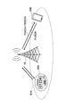
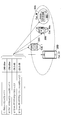
- FIG. 1 is a diagram for explaining a wireless communication system according to an embodiment of the present invention.
- the wireless communication system in the embodiment of the present invention includes a base station device 10 and a user device 20, as shown in FIG. FIG. 1 shows one each of the base station device 10, the user device 20A, and the user device 20B (hereinafter, referred to as “user device 20” when the user device 20A and the user device 20B are not distinguished). This is an example, and each may be larger in number.
- the base station device 10 is a communication device that provides one or more cells and performs wireless communication with the user device 20.
- the physical resource of the radio signal is defined in the time domain and the frequency domain, the time domain may be defined by the number of OFDM symbols, and the frequency domain may be defined by the number of subcarriers or the number of resource blocks.
- the base station device 10 transmits the synchronization signal and the system information to the user device 20.
- the synchronization signal is, for example, NR-PSS and NR-SSS.
- the system information is transmitted on the NR-PBCH, for example, and is also called broadcast information. As illustrated in FIG.
- the base station device 10 transmits a control signal or data to the user device 20 by DL (Downlink), and receives a control signal or data from the user device 20 by UL (Uplink). Both the base station apparatus 10 and the user apparatus 20 may be capable of performing beamforming and transmitting/receiving signals. Further, both the base station device 10 and the user device 20 may be able to apply MIMO (Multiple Input Multiple Output) communication to DL or UL. Moreover, both the base station apparatus 10 and the user apparatus 20 may communicate via SCell (Secondary Cell) and PCell (Primary Cell) by CA (Carrier Aggregation).
- SCell Secondary Cell
- PCell Primary Cell
- the user device 20A is a communication device having a wireless communication function such as a communication module for M2M (Machine-to-Machine), and the user device 20B has a wireless communication function such as a smartphone, a mobile phone, a tablet, a wearable terminal. It is a communication device.
- the user device 20 receives various control signals or data from the base station device 10 by DL and transmits various control signals or data to the base station device 10 by UL, thereby utilizing various communication services provided by the wireless communication system. ..
- the base station device 10 transmits a PDCCH (Physical Downlink Control Channel) or a PDSCH (Physical Downlink Shared Channel) to the user device 20.
- a PDCCH Physical Downlink Control Channel
- a PDSCH Physical Downlink Shared Channel
- the information regarding scheduling is transmitted to the user equipment 20 via the PDCCH
- the data is transmitted to the user equipment 20 via the PDSCH.
- the user apparatus 20 transmits PUSCH (Physical Downlink Shared Channel) to the base station apparatus 10 based on the information regarding scheduling.
- PUSCH Physical Downlink Shared Channel
- the user device 20A may be a BL (Bandwidth reduced Low complexity)-UE (User Equipment) with a limited bandwidth and reduced complexity.
- the BL-UE receives the system information block (for example, “SIB1-BR”) that is a set separated from the base station device 10.
- SIB1-BR system information block
- BL-UE has low transmission power and a small number of antennas.
- the UE category of BL-UE is category M1 or category M2. Both the category M1 and the category M2 may be the category M.
- the coverage of the BL-UE is narrower than that of the normal non-BL-UE. Here, the coverage refers to a range in which the connection can be maintained around the tower antenna of the cell.
- the user device 20B may be a non-BL-UE.
- the non-BL-UE realizes a higher data rate and has a higher transmission power than the BL-UE.
- the non-BL-UE uses a common system information block.
- the UE categories of the non-BL-UE are category 0, category 1, category 1bis, category 2, category 3 and the like.
- a non-BL-UE such as category 1 or category 1 bis may be used for M2M communication.
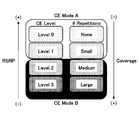
- FIG. 2 is a diagram for explaining the CE mode.
- the CE (Coverage Enhancement) mode is a mode in which BL-UE is assisted by repeatedly transmitting and receiving data in order to increase coverage under adverse conditions such as low transmission power.
- an M2M-UE for example, a smart meter installed in a house uses CE mode.
- CE mode A includes the case where the CE level is level 0 or level 1, and repeated transmission is supported at a relatively small number of times from 0 to 32 times.
- CE mode A coverage is assumed to be equivalent to UE category 1.
- CE mode B includes the case where the CE level is level 2 or level 3, and the repeated transmission is supported at a relatively large number of times from 192 times to 2048 times.
- the coverage in CE mode B is assumed to be equivalent to the coverage of +15 dB for UE category 1.
- RSRP Reference Signal Received Power
- the CE mode is mainly applied to BL-UE, but it is also possible to apply the CE mode to non-BL-UE.
- FIG. 3 is a diagram for explaining the determination of coverage in the CE mode.
- the user device 20 executes the determination based on the threshold value shown in FIG. 3 in order to determine the coverage of the user device 20.
- the user device 20 compares the measurement results Q rxlevmeas and Q qualmeas with the threshold values shown in FIG. 3.
- Q rxlevmeas indicates the measured reception level (RSRP)
- Q qualmeas indicates the measured quality level (RSRQ: Reference Signal Received Quality).
- Normal coverage is determined by Q rxlevmeas ⁇ Q rxlevmin and Q qualmeas ⁇ Q qualmin . That is, Q rxlevmin and Q qualmin are thresholds indicating the minimum required level for determining normal coverage.
- Extended coverage by CE mode A is determined by Q rxlevmin ⁇ Q rxlevmeas ⁇ Q rxlevmin_CE and Q qualmin ⁇ Q qualmeas ⁇ Q qualmin_CE . That is, Q rxlevmin_CE and Q qualmin_CE are thresholds indicating the minimum required level for determining extended coverage in CE mode A.
- Extended coverage in CE mode B is determined by Q rxlevmin_CE ⁇ Q rxlevmeas ⁇ Q rxlevmin_CE1 and Q qualmin_CE ⁇ Q qualmeas ⁇ Q qualmin_CE1 . That is, Q rxlevmin_CE1 and Q qualmin_CE1 are thresholds indicating the minimum required level for determining extended coverage in CE mode B.
- Q rxlevmin_CE1 ⁇ Q rxlevmeas and Q qualmin_CE1 ⁇ Q qualmeas are determined.
- thresholds are used for non-BL-UE and BL-UE. That is, as the thresholds Q rxlevmin and Q qualmin for determining normal coverage, different values are used for non-BL-UE and BL-UE. Q rxlevmin and Q qualmin are included in SIB1 and SIB1-BR, respectively.
- the same threshold value is used for the non-BL-UE and the BL-UE for the determination related to the extended coverage in the CE mode. That is, as the thresholds Q rxlevmin_CE , Q qualmin_CE , Q rxlevmin_CE1 and Q qualmin_CE1 , the same values are used in the non-BL-UE and the BL-UE. Q rxlevmin_CE , Q qualmin_CE , Q rxlevmin_CE1 and Q qualmin_CE1 are included only in SIB1-BR. As a result, it becomes difficult for the operator to optimize the threshold for determining the CE mode A and the CE mode B for the non-BL-UE and the BL-UE. For example, when both non-BL-UE and BL-UE are in the same cell by applying the CE mode, it is determined that the device is within the coverage even if transmission/reception cannot be actually performed. There is.
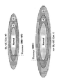
- FIG. 4 is a diagram for explaining an example (1) of coverage in CE mode.
- FIG. 4 illustrates the determination of normal coverage based on the threshold values shown in FIG.
- the area “Normal” shown in FIG. 4 corresponds to normal coverage
- the area “A” corresponds to extended coverage in CE mode A
- the area “B” corresponds to extended coverage in CE mode B.
- the threshold for determining normal coverage is set independently for non-BL-UE and BL-UE.
- the normal coverage of the BL-UE which is the category M
- Q rxlevmin included in SIB1-BR is determined by Q rxlevmin included in SIB1-BR.
- the normal coverage of the category 1 non-BL-UE is determined by Q rxlevmin included in SIB1.
- the threshold values for determining the CE mode A and the CE mode B are commonly set.
- a common threshold value that satisfies the region A or the region B satisfied by both the non-BL-UE and the BL-UE does not exist because the region A and the region B are different. Therefore, there is a discrepancy between the determination based on the commonly set threshold and the actual communication state of the UE.
- FIG. 5 is a diagram for explaining an example (2) of coverage in CE mode.
- FIG. 5 illustrates the determination of the extended coverage in the CE mode based on the threshold value shown in FIG.
- the area "Normal” shown in FIG. 5 corresponds to normal coverage
- the area "A” corresponds to extended coverage in CE mode A
- the area "B” corresponds to extended coverage in CE mode B.
- the non-BL-UE is the extended coverage of the CE mode B.
- the measurement result is worse than the threshold for determining the CE mode B, so it is determined to be out of coverage, and although communication is actually possible, communication cannot be performed.
- the non-BL-UE is located in the area “A” which is the extended coverage of the CE mode A, so that the non-BL-UE has the extended coverage of the CE mode B. It is determined to be located, and resources are excessively consumed by executing repeated transmissions in CE mode B even though communication is actually possible in CE mode A.
- FIG. 6 is a diagram for explaining an example (3) of coverage in CE mode.
- FIG. 6 illustrates determination of extended coverage in CE mode based on the threshold values shown in FIG.
- the area “Normal” shown in FIG. 6 corresponds to normal coverage
- the area “A” corresponds to extended coverage in CE mode A
- the area “B” corresponds to extended coverage in CE mode B.
- the BL-UE may be located outside the coverage. However, since the measurement result is better than the threshold for judging CE mode B, it is judged that it is located in the extended coverage of CE mode B, and the repeated transmission of CE mode B is executed despite the fact that communication is actually impossible. Excessively consumes resources. Further, although the BL-UE is located in the area “B” which is the extended coverage of the CE mode B, the BL-UE is located in the extended coverage of the CE mode A because the measurement result is better than the threshold for determining the CE mode A. It is determined that the communication is difficult because the CE mode A is used although the communication is actually possible in the CE mode B.
- non-BL-UE and BL-UE are allowed to individually set thresholds for determining extended coverage.
- the non-BL-UE and the BL-UE are notified of the threshold value for determining the separated extended coverage.
- the non-BL-UE and the BL-UE each acquire a threshold value for determining appropriate extended coverage based on whether or not the user apparatus 20 is the BL-UE.
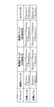
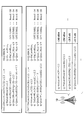
- FIG. 7 is a specification modification example (1) related to the CE mode in the embodiment of the present invention.
- the operator uses the thresholds “q-RxLevMinCE-nonBL-r13” and “threshold” used for the determination in the additional CE mode used by the non-BL-UE.
- the user device 20 may be configured to be notified of “q-QualMinRSRQ-CE-nonBL-r13”, “q-RxLevMinCE1-nonBL-r13”, and “q-QualMinRSRQ-CE1-nonBL-r13”.
- the name of the information element is an example, and another name may be used.
- the threshold values “ ⁇ 150 dBm” and “ ⁇ 22.5 dB” shown in FIG. 7 are examples, and other values may be used.
- FIG. 8 is a specification modification example (2) related to the CE mode in the embodiment of the present invention.
- user equipment 20A of UE category M that is BL-UE
- user equipment 20B of UE category 1bis that is non-BL-UE
- user equipment 20C of UE category 1
- user equipment of UE category 2+ The 20D selects the threshold value used for the determination in the CE mode notified from the base station device 10 based on whether or not the device itself is the BL-UE.
- the user apparatus 20A is a BL-UE and thus selects “q-RxLevMinCE-r13” and “q-QualMinRSRQ-CE1-r13”.
- the user apparatus 20B, the user apparatus 20C, and the user apparatus 20D select "q-RxLevMinCE-nonBL-r13" and “q-QualMinRSRQ-CE1-nonBL-r13" because they are not BL-UE.
- FIG. 9 is a specification modification example (3) related to the CE mode in the embodiment of the present invention.
- the operator may set the threshold used for the determination in the additional CE mode used by the non-BL-UE or the BL-UE for each UE category.
- “q-RxLevMinCE-Cat1-r13”, “q-QualMinRSRQ-CE-Cat1-r13”, “q-RxLevMinCE1-Cat1-r13” are set as the threshold values for the user equipment 20 of UE category 1.
- “Q-QualMinRSRQ-CE1-Cat1-r13” may be set.
- q-RxLevMinCE-Cat1bis-r13 “q-QualMinRSRQ-CE-Cat1bis-r13”, “q-RxLevMinCE1-Cat1bis-r13”, “q-QualMinRs” are set as the threshold values for the user equipment 20 of the UE category 1bis. -CE1-Cat1bis-r13” may be set. Similarly, as threshold values for the user equipment 20 of the UE category M, "q-RxLevMinCE-CatM-r13”, “q-QualMinRSRQ-CE-CatM-r13", “q-RxLevMinCE1-CatM-r13", “q-QualMinRSRQ-”.
- CE1-CatM-r13 may be set.
- the name of the information element is an example, and another name may be used.
- the threshold values “ ⁇ 143 dBm”, “ ⁇ 146 dBm”, “ ⁇ 150 dBm” and the like shown in FIG. 9 are examples, and other values may be used.
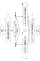
- FIG. 10 is a flowchart for explaining an operation example related to the CE mode according to the embodiment of the present invention. An operation example relating to selection of a threshold value used for determination in the CE mode in the user device 20 will be described with reference to FIG. 10.
- step S11 the user device 20 receives from the base station device 10 the threshold value used for the determination in the CE mode.
- the base station device 10 may notify the user device 20 of the threshold value used for the determination in the CE mode via broadcast information or another RRC (Radio Resource Control) message.
- the user apparatus 20 determines whether the own apparatus is BL-UE or non-BL-UE.
- the process proceeds to step S13, and when the own device is the non-BL-UE, the process proceeds to step S14.
- step S13 the user apparatus 20 uses the threshold value used for the determination in the CE mode corresponding to BL-UE.
- step S14 the user apparatus 20 uses the threshold value used for the determination in the CE mode corresponding to non-BL-UE.
- step S15 when the threshold used for determination in the CE mode for each UE category is notified from the base station device 10, the user device 20 sets the threshold used for determination in the CE mode corresponding to the UE category of the own device. May be used.
- the threshold value used for the determination in the CE mode according to the capabilities of each user device 20 is individually set. Therefore, it is possible to accurately determine and display whether the own device is within the coverage or out of the coverage in various situations.
- the base station device 10 and the user device 20 include a function for implementing the above-described embodiment. However, each of the base station device 10 and the user device 20 may be provided with only a part of the functions in the embodiment.
- FIG. 11 is a diagram showing an example of a functional configuration of the base station device 10.
- the base station device 10 includes a transmission unit 110, a reception unit 120, a setting unit 130, and a control unit 140.
- the functional configuration shown in FIG. 11 is merely an example. As long as the operation according to the embodiment of the present invention can be executed, the function categories and the names of the function units may be any names.
- the transmitting unit 110 includes a function of generating a signal to be transmitted to the user device 20 side and wirelessly transmitting the signal.
- the reception unit 120 includes a function of receiving various signals transmitted from the user device 20 and acquiring, for example, information of a higher layer from the received signals. Further, the transmission unit 110 has a function of transmitting NR-PSS, NR-SSS, NR-PBCH, DL/UL control signal, DL/UL data signal, etc. to the user apparatus 20.
- the setting unit 130 stores preset setting information and various setting information to be transmitted to the user device 20 in the storage device, and reads it from the storage device as necessary.
- the content of the setting information is, for example, the setting related to the CE mode of the user device 20.
- the control unit 140 schedules the user device 20 and controls transmission of downlink data and reception of uplink data, as described in the embodiment.
- the control unit 140 transmits the setting related to the CE mode to the user device 20.
- the functional unit related to signal transmission in the control unit 140 may be included in the transmission unit 110, and the functional unit related to signal reception in the control unit 140 may be included in the reception unit 120.
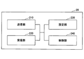
- FIG. 12 is a diagram illustrating an example of a functional configuration of the user device 20.
- the user device 20 includes a transmission unit 210, a reception unit 220, a setting unit 230, and a control unit 240.
- the functional configuration shown in FIG. 12 is merely an example. As long as the operation according to the embodiment of the present invention can be executed, the function categories and the names of the function units may be any names.
- the transmitter 210 creates a transmission signal from the transmission data and wirelessly transmits the transmission signal.
- the receiving unit 220 wirelessly receives various signals and acquires signals of higher layers from the received physical layer signals. Further, the receiving section 220 has a function of receiving NR-PSS, NR-SSS, NR-PBCH, DL/UL/SL control signals and the like transmitted from the base station apparatus 10.
- the transmission unit 210 performs P2CH communication to other user apparatuses 20 by using a PSCCH (Physical Sidelink Control Channel), a PSSCH (Physical Sidelink Shared Channel), a PSDCH (Physical Sidelink Discovery Channel), and a PSBCH (Physical Sidelink Broadcast Channel). ) Etc., and the receiving part 120 receives PSCCH, PSSCH, PSDCH, PSBCH, etc. from the other user apparatus 20.
- PSCCH Physical Sidelink Control Channel
- PSSCH Physical Sidelink Shared Channel
- PSDCH Physical Sidelink Discovery Channel
- PSBCH Physical Sidelink Broadcast Channel
- the setting unit 230 stores various setting information received from the base station device 10 or the user device 20 by the receiving unit 220 in a storage device, and reads from the storage device as necessary.
- the setting unit 230 also stores preset setting information.
- the content of the setting information is, for example, the setting related to the CE mode of the user device 20.
- the control unit 240 controls the reception of downlink data and the transmission of uplink data based on the scheduling acquired from the base station device 10, as described in the embodiment. In addition, the control unit 240 executes communication control to which the setting related to the CE mode received from the base station device 10 is applied.
- the functional unit related to signal transmission in the control unit 240 may be included in the transmission unit 210, and the functional unit related to signal reception in the control unit 240 may be included in the reception unit 220.
- each functional block may be realized by using one device physically or logically coupled, or directly or indirectly (for example, two or more devices physically or logically separated). , Wired, wireless, etc.) and may be implemented using these multiple devices.
- the functional block may be implemented by combining the one device or the plurality of devices with software.
- Functions include judgment, decision, judgment, calculation, calculation, processing, derivation, investigation, search, confirmation, reception, transmission, output, access, resolution, selection, selection, establishment, comparison, assumption, expectation, observation, Broadcasting, notifying, communicating, forwarding, configuring, reconfiguring, allocating, mapping, assigning, etc., but not limited to these.
- I can't.
- functional blocks (components) that function transmission are called a transmitting unit and a transmitter.
- the implementation method is not particularly limited.
- the base station device 10, the user device 20, and the like according to the embodiment of the present disclosure may function as a computer that performs the process of the wireless communication method of the present disclosure.
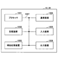
- FIG. 13 is a diagram illustrating an example of a hardware configuration of the base station device 10 and the user device 20 according to the embodiment of the present disclosure.
- the base station device 10 and the user device 20 described above are physically configured as a computer device including a processor 1001, a storage device 1002, an auxiliary storage device 1003, a communication device 1004, an input device 1005, an output device 1006, a bus 1007, and the like. May be done.
- the word “apparatus” can be read as a circuit, device, unit, or the like.
- the hardware configurations of the base station device 10 and the user device 20 may be configured to include one or a plurality of each device illustrated in the figure, or may be configured not to include some devices.
- Each function in the base station device 10 and the user device 20 causes a predetermined software (program) to be loaded onto hardware such as the processor 1001, the storage device 1002, etc., so that the processor 1001 performs an arithmetic operation and communication by the communication device 1004. It is realized by controlling or at least one of reading and writing of data in the storage device 1002 and the auxiliary storage device 1003.
- the processor 1001 operates an operating system to control the entire computer, for example.
- the processor 1001 may be configured by a central processing unit (CPU) including an interface with peripheral devices, a control device, a calculation device, a register, and the like.
- CPU central processing unit
- the control unit 140, the control unit 240, and the like described above may be realized by the processor 1001.
- the processor 1001 reads a program (program code), a software module, data or the like from at least one of the auxiliary storage device 1003 and the communication device 1004 to the storage device 1002, and executes various processes according to these.
- a program that causes a computer to execute at least part of the operations described in the above-described embodiments is used.
- the control unit 140 of the base station device 10 illustrated in FIG. 11 may be realized by a control program stored in the storage device 1002 and operated by the processor 1001.
- the control unit 240 of the user device 20 illustrated in FIG. 12 may be realized by a control program stored in the storage device 1002 and operated by the processor 1001.
- the various processes described above are executed by one processor 1001, they may be executed simultaneously or sequentially by two or more processors 1001.
- the processor 1001 may be implemented by one or more chips.
- the program may be transmitted from the network via an electric communication line.
- the storage device 1002 is a computer-readable recording medium, and is, for example, at least one of ROM (Read Only Memory), EPROM (Erasable Programmable ROM), EEPROM (ElectricallyErasable Programmable ROM), RAM (Random Access Memory), and the like. It may be configured.
- the storage device 1002 may be called a register, a cache, a main memory (main storage device), or the like.
- the storage device 1002 can store an executable program (program code), a software module, or the like for implementing the communication method according to the embodiment of the present disclosure.
- the auxiliary storage device 1003 is a computer-readable recording medium, and is, for example, an optical disc such as a CD-ROM (Compact Disc ROM), a hard disk drive, a flexible disc, a magneto-optical disc (for example, a compact disc, a digital versatile disc, a Blu disc). -Ray disk), smart card, flash memory (eg card, stick, key drive), floppy disk, magnetic strip, etc.
- the above-described storage medium may be, for example, a database including at least one of the storage device 1002 and the auxiliary storage device 1003, a server, or another appropriate medium.
- the communication device 1004 is hardware (transmission/reception device) for performing communication between computers via at least one of a wired network and a wireless network, and is also called, for example, a network device, a network controller, a network card, a communication module, or the like.
- the communication device 1004 includes, for example, a high frequency switch, a duplexer, a filter, a frequency synthesizer, etc. in order to realize at least one of a frequency division duplex (FDD: Frequency Division Duplex) and a time division duplex (TDD: Time Division Duplex). May be composed of
- FDD Frequency Division Duplex
- TDD Time Division Duplex
- the transmitter/receiver may be implemented by physically or logically separating the transmitter and the receiver.
- the input device 1005 is an input device (eg, keyboard, mouse, microphone, switch, button, sensor, etc.) that receives an input from the outside.
- the output device 1006 is an output device (for example, a display, a speaker, an LED lamp, etc.) that outputs to the outside.
- the input device 1005 and the output device 1006 may be integrated (for example, a touch panel).
- each device such as the processor 1001 and the storage device 1002 is connected by a bus 1007 for communicating information.
- the bus 1007 may be configured using a single bus, or may be configured using different buses for each device.
- the base station device 10 and the user device 20 include a microprocessor, a digital signal processor (DSP: Digital Signal Processor), an ASIC (Application Specific Integrated Circuit), a PLD (Programmable Logic Device), an FPGA (Field Programmable Gate Array), and the like. It may be configured to include hardware, and the hardware may implement part or all of each functional block. For example, the processor 1001 may be implemented using at least one of these hardware.
- DSP Digital Signal Processor
- ASIC Application Specific Integrated Circuit
- PLD Programmable Logic Device
- FPGA Field Programmable Gate Array
- the receiving unit that receives from the base station device a plurality of thresholds for use in the determination in the coverage extension mode, and whether its own device is a predetermined type Based on whether or not the control unit selects a threshold value used for the determination in the coverage extension mode from the received plurality of threshold values, and a threshold value used for the determination in the selected coverage extension mode, the coverage extension mode.
- a user equipment having a communication unit for communicating with the base station apparatus in extended coverage for use in determining the coverage in.
- the threshold value used for the determination in the CE mode according to the capabilities of each user device 20 is individually set. Therefore, in various situations, it is possible to accurately determine and display whether the own device is within the coverage or out of the coverage. That is, it is possible to apply the coverage extension mode according to the capability of the user equipment.
- the predetermined type may be BL (Bandwidth reduced Low complexity)-UE (User Equipment).
- BL Bitwidth reduced Low complexity
- UE User Equipment
- the predetermined type may be a UE category.
- the user device 20 can change the threshold value used for the coverage determination according to the UE category of its own device and execute an appropriate coverage extension operation.
- the predetermined type may be a UE category corresponding to non-BL-UE.
- the user apparatus 20 can change the threshold value used for the coverage determination and execute an appropriate coverage extension operation according to the UE category when the own apparatus is a non-BL-UE.
- the predetermined type may be a UE category corresponding to BL-UE.
- the user apparatus 20 can change the threshold value used for the coverage determination and execute an appropriate coverage extension operation according to the UE category when the own apparatus is a BL-UE.
- a transmission unit that transmits to the user device a plurality of threshold values to be used for the determination in the coverage extension mode selected based on whether or not the user device is of a predetermined type. And a threshold for use in the determination in the coverage extension mode is used in the determination of the coverage in the coverage extension mode, and a base station apparatus having a communication unit that communicates with the user apparatus in the extended coverage is provided. ..
- the threshold value used for the determination in the CE mode according to the capabilities of each user device 20 is individually set. Therefore, in various situations, it is possible to accurately determine and display whether the own device is within the coverage or out of the coverage. That is, it is possible to apply the coverage extension mode according to the capability of the user equipment.
- the operation of the plurality of functional units may be physically performed by one component, or the operation of one functional unit may be physically performed by the plurality of components.
- the order of processing may be changed as long as there is no contradiction.
- the base station apparatus 10 and the user apparatus 20 have been described using functional block diagrams for convenience of processing description, such an apparatus may be realized by hardware, software, or a combination thereof.
- the software operated by the processor included in the base station device 10 according to the embodiment of the present invention and the software operated by the processor included in the user device 20 according to the embodiment of the present invention are respectively a random access memory (RAM), a flash memory, and a read memory. It may be stored in a dedicated memory (ROM), EPROM, EEPROM, register, hard disk (HDD), removable disk, CD-ROM, database, server, or any other suitable storage medium.
- the notification of information is not limited to the mode/embodiment described in the present disclosure, and may be performed using another method.
- information is notified by physical layer signaling (for example, DCI (Downlink Control Information), UCI (Uplink Control Information)), upper layer signaling (for example, RRC (Radio Resource Control) signaling, MAC (Medium Access Control) signaling, It may be implemented by broadcast information (MIB (Master Information Block), SIB (System Information Block)), other signals, or a combination thereof, and RRC signaling may be called an RRC message, for example, RRC message. It may be a connection setup (RRC Connection Setup) message, an RRC connection reconfiguration message, or the like.
- LTE Long Term Evolution
- LTE-A Long Term Evolution-Advanced
- SUPER 3G IMT-Advanced
- 4G fourth generation mobile communication system
- 5G 5th generation mobile communication system
- FRA Full Radio Access
- NR new Radio
- W-CDMA registered trademark
- GSM registered trademark
- CDMA2000 Code Division Multiple Access 2000
- UMB Universal Mobile Broadband
- IEEE 802.11 Wi-Fi (registered trademark)
- IEEE 802.16 WiMAX (registered trademark)
- IEEE 802.20 UWB (Ultra-WideBand)
- Bluetooth registered trademark
- other systems using appropriate systems, and extensions based on these It may be applied to at least one of the next-generation systems.
- a plurality of systems may be combined and applied (for example, a combination of at least one of LTE and LTE-A and 5G).
- the specific operation that is assumed to be performed by the base station device 10 in this specification may be performed by its upper node in some cases.
- various operations performed for communication with the user device 20 are other than the base station device 10 and the base station device 10. It is clear that it can be performed by at least one of the network nodes of (for example, but not limited to, MME or S-GW, etc.).
- the other network node may be a combination of a plurality of other network nodes (for example, MME and S-GW). Good.
- Information, signals, etc. described in the present disclosure may be output from the upper layer (or lower layer) to the lower layer (or upper layer). Input/output may be performed via a plurality of network nodes.
- Information that has been input and output may be stored in a specific location (for example, memory), or may be managed using a management table. Information that is input/output may be overwritten, updated, or added. The output information and the like may be deleted. The input information and the like may be transmitted to another device.
- the determination in the present disclosure may be performed by a value (0 or 1) represented by 1 bit, may be performed by a Boolean value (Boolean: true or false), and may be performed by comparing numerical values (for example, , Comparison with a predetermined value).
- software, instructions, information, etc. may be transmitted and received via a transmission medium.
- the software uses a wired technology (coaxial cable, optical fiber cable, twisted pair, digital subscriber line (DSL: Digital Subscriber Line), etc.) and/or wireless technology (infrared, microwave, etc.) websites, When sent from a server, or other remote source, at least one of these wired and wireless technologies is included within the definition of transmission medium.
- wired technology coaxial cable, optical fiber cable, twisted pair, digital subscriber line (DSL: Digital Subscriber Line), etc.
- wireless technology infrared, microwave, etc.
- data, instructions, commands, information, signals, bits, symbols, chips, etc. that may be referred to throughout the above description include voltage, current, electromagnetic waves, magnetic fields or magnetic particles, optical fields or photons, or any of these. May be represented by a combination of
- At least one of the channel and the symbol may be a signal (signaling).
- the signal may also be a message.
- a component carrier CC:Component Carrier
- CC Component Carrier
- system and “network” used in this disclosure are used interchangeably.
- the information, parameters, etc. described in the present disclosure may be represented by using an absolute value, may be represented by using a relative value from a predetermined value, or by using other corresponding information. May be represented.
- the radio resources may be those indicated by the index.
- base station Base Station
- radio base station base station
- base station device fixed station
- NodeB NodeB
- eNodeB eNodeB
- GNB nodeB
- access point access point
- transmission point transmission point
- reception point transmission/reception point
- cell cell
- cell group carrier
- component carrier component carrier
- a base station can accommodate one or more (eg, three) cells.
- a base station accommodates multiple cells, the entire coverage area of the base station can be divided into multiple smaller areas, each smaller area being defined by a base station subsystem (eg, indoor small base station (RRH: It is also possible to provide communication services by Remote Radio Head).
- RRH indoor small base station
- the term "cell” or “sector” means a part or the whole coverage area of at least one of the base station and the base station subsystem that perform communication services in this coverage. Refers to.
- MS Mobile Station
- UE User Equipment
- Mobile stations are defined by those skilled in the art as subscriber stations, mobile units, subscriber units, wireless units, remote units, mobile devices, wireless devices, wireless communication devices, remote devices, mobile subscriber stations, access terminals, mobile terminals, wireless. It may also be referred to as a terminal, remote terminal, handset, user agent, mobile client, client, or some other suitable term.
- At least one of the base station and the mobile station may be called a transmission device, a reception device, a communication device, or the like.
- the base station and the mobile station may be a device mounted on the mobile body, the mobile body itself, or the like.
- the moving body may be a vehicle (eg, car, airplane, etc.), an unmanned moving body (eg, drone, self-driving car, etc.), or a robot (manned or unmanned).
- At least one of the base station and the mobile station also includes a device that does not necessarily move during communication operation.
- at least one of the base station and the mobile station may be an IoT (Internet of Things) device such as a sensor.
- IoT Internet of Things
- the base station in the present disclosure may be replaced by the user terminal.
- the communication between the base station and the user terminal is replaced with communication between a plurality of user devices 20 (for example, it may be called D2D (Device-to-Device), V2X (Vehicle-to-Everything), etc.).
- D2D Device-to-Device
- V2X Vehicle-to-Everything
- the user apparatus 20 may have the function of the base station apparatus 10 described above.
- the words such as “up” and “down” may be replaced with the words corresponding to the terminal-to-terminal communication (for example, “side”).
- the uplink channel and the downlink channel may be replaced with the side channel.
- the user terminal in the present disclosure may be replaced by the base station.
- the base station may have the function of the above-mentioned user terminal.
- determining and “determining” as used in this disclosure may encompass a wide variety of actions.
- “Judgment” and “decision” are, for example, judgment, calculating, computing, processing, deriving, investigating, and looking up, search, inquiry. (Eg, searching in a table, database, or another data structure), considering ascertaining as “judging” or “deciding”, and the like.
- “decision” and “decision” include receiving (eg, receiving information), transmitting (eg, transmitting information), input (input), output (output), access (accessing) (for example, accessing data in a memory) may be regarded as “judging” or “deciding”.
- judgment and “decision” are considered to be “judgment” and “decision” when things such as resolving, selecting, choosing, selecting, establishing, and comparing are done. May be included. That is, the “judgment” and “decision” may include considering some action as “judgment” and “decision”. In addition, “determination (decision)” may be read as “assuming”, “expecting”, “considering”, and the like.
- connection means any direct or indirect connection or coupling between two or more elements, and It can include the presence of one or more intermediate elements between two elements that are “connected” or “coupled.”
- the connections or connections between the elements may be physical, logical, or a combination thereof.
- connection may be read as “access”.
- two elements are in the radio frequency domain, with at least one of one or more wires, cables and printed electrical connections, and as some non-limiting and non-exhaustive examples. , Can be considered to be “connected” or “coupled” to each other, such as with electromagnetic energy having wavelengths in the microwave and light (both visible and invisible) regions.
- the reference signal may be abbreviated as RS (Reference Signal), or may be referred to as a pilot (Pilot) depending on the applied standard.
- RS Reference Signal
- Pilot pilot
- the phrase “based on” does not mean “based only on,” unless expressly specified otherwise. In other words, the phrase “based on” means both "based only on” and “based at least on.”
- references to elements using designations such as “first”, “second”, etc. used in this disclosure does not generally limit the amount or order of those elements. These designations may be used in this disclosure as a convenient way to distinguish between two or more elements. Thus, references to the first and second elements do not mean that only two elements may be employed, or that the first element must precede the second element in any way.
- a radio frame may be composed of one or more frames in the time domain. Each frame or frames in the time domain may be referred to as a subframe. A subframe may also be composed of one or more slots in the time domain. A subframe may have a fixed time length (eg, 1 ms) that does not depend on numerology.
- Numerology may be a communication parameter applied to at least one of transmission and reception of a certain signal or channel.
- Numerology includes, for example, subcarrier spacing (SCS: SubCarrier Spacing), bandwidth, symbol length, cyclic prefix length, transmission time interval (TTI: Transmission Time Interval), number of symbols per TTI, radio frame configuration, transceiver At least one of specific filtering processing performed in the frequency domain and specific windowing processing performed by the transceiver in the time domain may be shown.
- a slot may be composed of one or more symbols (OFDM (Orthogonal Frequency Division Multiplexing) symbol, SC-FDMA (Single Carrier Frequency Division Multiple Access) symbol, etc.) in the time domain.
- a slot may be a time unit based on numerology.
- a slot may include multiple minislots. Each minislot may be composed of one or more symbols in the time domain. The minislot may also be called a subslot. Minislots may be configured with fewer symbols than slots.
- a PDSCH (or PUSCH) transmitted in a time unit larger than a minislot may be referred to as PDSCH (or PUSCH) mapping type A.
- the PDSCH (or PUSCH) transmitted using the minislot may be referred to as PDSCH (or PUSCH) mapping type B.
- Radio frame, subframe, slot, minislot, and symbol all represent the time unit for signal transmission. Radio frames, subframes, slots, minislots, and symbols may have different names corresponding to them.
- one subframe may be called a transmission time interval (TTI)
- TTI transmission time interval
- TTI transmission time interval
- TTI transmission time interval
- TTI transmission time interval
- TTI means, for example, a minimum time unit of scheduling in wireless communication.
- the base station performs scheduling to allocate radio resources (frequency bandwidth that can be used in each user device 20, transmission power, etc.) to each user device 20 in units of TTI.
- the definition of TTI is not limited to this.
- the TTI may be a transmission time unit of a channel-encoded data packet (transport block), code block, codeword, or the like, or may be a processing unit of scheduling, link adaptation, or the like.
- the time interval for example, the number of symbols
- the transport block, code block, codeword, etc. may be shorter than the TTI.
- one slot or one minislot is called a TTI
- one or more TTIs may be the minimum time unit for scheduling.
- the number of slots (the number of mini-slots) forming the minimum time unit of the scheduling may be controlled.
- a TTI having a time length of 1 ms may be called a normal TTI (TTI in LTE Rel. 8-12), a normal TTI, a long TTI, a normal subframe, a normal subframe, a long subframe, a slot, or the like.
- a TTI shorter than the normal TTI may be called a shortened TTI, a short TTI, a partial TTI (partial or fractional TTI), a shortened subframe, a short subframe, a minislot, a subslot, a slot, and the like.
- a long TTI (eg, normal TTI, subframe, etc.) may be read as a TTI having a time length exceeding 1 ms, and a short TTI (eg, shortened TTI, etc.) is less than the TTI length of the long TTI and 1 ms. It may be read as a TTI having the above TTI length.
- a resource block is a resource allocation unit in the time domain and the frequency domain, and may include one or a plurality of continuous subcarriers in the frequency domain.
- the number of subcarriers included in the RB may be the same regardless of the numerology, and may be 12, for example.
- the number of subcarriers included in the RB may be determined based on numerology.
- the time domain of the RB may include one or more symbols, and may be 1 slot, 1 minislot, 1 subframe, or 1 TTI in length.
- One TTI, one subframe, etc. may be configured with one or a plurality of resource blocks.
- one or more RBs include a physical resource block (PRB: Physical RB), a subcarrier group (SCG: Sub-Carrier Group), a resource element group (REG: Resource Element Group), a PRB pair, an RB pair, etc. May be called.
- PRB Physical resource block
- SCG Sub-Carrier Group
- REG Resource Element Group
- a resource block may be composed of one or more resource elements (RE: Resource Element).
- RE Resource Element
- 1 RE may be a radio resource area of 1 subcarrier and 1 symbol.
- a bandwidth part (may also be called a partial bandwidth) may represent a subset of consecutive common RBs (common resource blocks) for a certain numerology in a certain carrier.
- the common RB may be specified by the index of the RB based on the common reference point of the carrier.
- PRBs may be defined in a BWP and numbered within the BWP.
- BWP may include BWP for UL (UL BWP) and BWP for DL (DL BWP).
- BWP for UL
- DL BWP DL BWP
- one or more BWPs may be set in one carrier.
- At least one of the configured BWPs may be active, and the UE does not have to expect to send and receive a given signal/channel outside the active BWP.
- “cell”, “carrier”, and the like in the present disclosure may be read as “BWP”.
- the structure of the wireless frame, subframe, slot, minislot, symbol, etc. described above is just an example.
- the number of subframes included in a radio frame, the number of slots per subframe or radio frame, the number of minislots included in a slot, the number of symbols and RBs included in a slot or minislot, and included in RBs The number of subcarriers, the number of symbols in the TTI, the symbol length, the cyclic prefix (CP: Cyclic Prefix) length, and the like can be variously changed.
- the term “A and B are different” may mean “A and B are different from each other”.
- the term may mean that “A and B are different from C”.
- the terms “remove”, “coupled” and the like may be construed similarly as “different”.
- the notification of the predetermined information (for example, the notification of “being X”) is not limited to the explicit notification, and is performed implicitly (for example, the notification of the predetermined information is not performed). Good.
- the transmission unit 210 and the reception unit 220 are examples of the communication unit.
- the non-BL-UE is an example of the non-BL-UE.
- the transmission unit 110 and the reception unit 120 are an example of a communication unit.
- base station device 110 transmission unit 120 reception unit 130 setting unit 140 control unit 20 user device 210 transmission unit 220 reception unit 230 setting unit 240 control unit 1001 processor 1002 storage device 1003 auxiliary storage device 1004 communication device 1005 input device 1006 output device
Landscapes
- Engineering & Computer Science (AREA)
- Computer Networks & Wireless Communication (AREA)
- Signal Processing (AREA)
- Databases & Information Systems (AREA)
- Quality & Reliability (AREA)
- Computer Security & Cryptography (AREA)
- Mobile Radio Communication Systems (AREA)
Abstract
La présente invention concerne un dispositif utilisateur comprenant : une unité de réception qui reçoit en provenance d'un dispositif de station de base une pluralité de valeurs seuil à utiliser pour une détermination dans un mode d'amélioration de couverture ; une unité de commande qui, sur la base du fait que le dispositif d'utilisateur est d'un type prescrit, sélectionne parmi la pluralité de valeurs seuil reçues une valeur seuil à utiliser pour la détermination dans le mode d'amélioration de couverture ; et une unité de communication qui communique avec le dispositif de station de base dans une couverture améliorée, à l'aide de la valeur seuil sélectionnée à utiliser pour la détermination dans le mode d'amélioration de couverture pour une détermination de couverture dans le mode d'amélioration de couverture.
Applications Claiming Priority (2)
| Application Number | Priority Date | Filing Date | Title |
|---|---|---|---|
| JP2019-030370 | 2019-02-22 | ||
| JP2019030370A JP2022065209A (ja) | 2019-02-22 | 2019-02-22 | ユーザ装置及び基地局装置 |
Publications (1)
| Publication Number | Publication Date |
|---|---|
| WO2020171182A1 true WO2020171182A1 (fr) | 2020-08-27 |
Family
ID=72144479
Family Applications (1)
| Application Number | Title | Priority Date | Filing Date |
|---|---|---|---|
| PCT/JP2020/006892 Ceased WO2020171182A1 (fr) | 2019-02-22 | 2020-02-20 | Dispositif utilisateur et dispositif de station de base |
Country Status (2)
| Country | Link |
|---|---|
| JP (1) | JP2022065209A (fr) |
| WO (1) | WO2020171182A1 (fr) |
Cited By (2)
| Publication number | Priority date | Publication date | Assignee | Title |
|---|---|---|---|---|
| US11375509B2 (en) * | 2018-02-16 | 2022-06-28 | Nokia Technologies Oy | Support for receive-limited user equipment in wireless environments |
| WO2026034100A1 (fr) * | 2024-08-06 | 2026-02-12 | パナソニック インテレクチュアル プロパティ コーポレーション オブ アメリカ | Dispositif de communication, station de base et procédé de communication |
Citations (1)
| Publication number | Priority date | Publication date | Assignee | Title |
|---|---|---|---|---|
| JP2018026738A (ja) * | 2016-08-10 | 2018-02-15 | 株式会社Nttドコモ | 基地局及び信号送信方法 |
-
2019
- 2019-02-22 JP JP2019030370A patent/JP2022065209A/ja active Pending
-
2020
- 2020-02-20 WO PCT/JP2020/006892 patent/WO2020171182A1/fr not_active Ceased
Patent Citations (1)
| Publication number | Priority date | Publication date | Assignee | Title |
|---|---|---|---|---|
| JP2018026738A (ja) * | 2016-08-10 | 2018-02-15 | 株式会社Nttドコモ | 基地局及び信号送信方法 |
Non-Patent Citations (2)
| Title |
|---|
| NTT DOCOMO INC.: "CE Mode Threshold Adjustments for non-BL and BL UE in Standalone", 3GPP TSG RAN WG2 #106 R2-1908080, 9 May 2019 (2019-05-09), XP051740279 * |
| NTT DOCOMO INC.: "CE Mode Threshold Adjustments for non-BL and BL UE", 3GPP TSG RAN WG2 #108 R2-1914474, 8 November 2019 (2019-11-08), XP051816554 * |
Cited By (2)
| Publication number | Priority date | Publication date | Assignee | Title |
|---|---|---|---|---|
| US11375509B2 (en) * | 2018-02-16 | 2022-06-28 | Nokia Technologies Oy | Support for receive-limited user equipment in wireless environments |
| WO2026034100A1 (fr) * | 2024-08-06 | 2026-02-12 | パナソニック インテレクチュアル プロパティ コーポレーション オブ アメリカ | Dispositif de communication, station de base et procédé de communication |
Also Published As
| Publication number | Publication date |
|---|---|
| JP2022065209A (ja) | 2022-04-27 |
Similar Documents
| Publication | Publication Date | Title |
|---|---|---|
| JPWO2020090098A1 (ja) | ユーザ装置及び基地局装置 | |
| US20220287108A1 (en) | Terminal and communication method | |
| WO2020194638A1 (fr) | Dispositif utilisateur et dispositif de station de base | |
| JPWO2020095455A1 (ja) | ユーザ装置及び基地局装置 | |
| WO2021199415A1 (fr) | Terminal et procédé de communication | |
| WO2020100559A1 (fr) | Équipement utilisateur et appareil de station de base | |
| WO2020194636A1 (fr) | Équipement utilisateur | |
| WO2020157873A1 (fr) | Dispositif d'utilisateur et dispositif de station de base | |
| WO2020170405A1 (fr) | Équipement utilisateur et appareil de station de base | |
| WO2021181707A1 (fr) | Terminal et procédé de communication | |
| WO2021149246A1 (fr) | Terminal, station de base, et procédé de communication | |
| JP7552992B2 (ja) | 端末、通信システム及び通信方法 | |
| WO2020194746A1 (fr) | Dispositif utilisateur et dispositif de station de base | |
| WO2020174552A1 (fr) | Dispositif utilisateur et procédé de communication | |
| JPWO2020161907A1 (ja) | ユーザ装置 | |
| WO2020171182A1 (fr) | Dispositif utilisateur et dispositif de station de base | |
| JP7296461B2 (ja) | 基地局装置、端末、及び送信方法 | |
| WO2021149110A1 (fr) | Terminal et procédé de communication | |
| WO2020246185A1 (fr) | Terminal et station de base | |
| WO2021140676A1 (fr) | Terminal et procédé de communication | |
| WO2020170445A1 (fr) | Dispositif utilisateur et dispositif de station de base | |
| WO2021014621A1 (fr) | Terminal et procédé de communication | |
| WO2020157874A1 (fr) | Dispositif utilisateur et dispositif de station de base | |
| JP7674471B2 (ja) | 端末、通信方法、基地局及び無線通信システム | |
| JP7427687B2 (ja) | 端末、通信システム、及び通信方法 |
Legal Events
| Date | Code | Title | Description |
|---|---|---|---|
| 121 | Ep: the epo has been informed by wipo that ep was designated in this application |
Ref document number: 20758698 Country of ref document: EP Kind code of ref document: A1 |
|
| NENP | Non-entry into the national phase |
Ref country code: DE |
|
| 122 | Ep: pct application non-entry in european phase |
Ref document number: 20758698 Country of ref document: EP Kind code of ref document: A1 |
|
| NENP | Non-entry into the national phase |
Ref country code: JP |