WO2020171209A1 - Tuyau en acier à haute résistance soudé par résistance électrique, et procédé d'utilisation d'un tuyau en acier à haute résistance soudé par résistance électrique sur un chantier de construction pour stabiliser des fondations - Google Patents
Tuyau en acier à haute résistance soudé par résistance électrique, et procédé d'utilisation d'un tuyau en acier à haute résistance soudé par résistance électrique sur un chantier de construction pour stabiliser des fondations Download PDFInfo
- Publication number
- WO2020171209A1 WO2020171209A1 PCT/JP2020/007101 JP2020007101W WO2020171209A1 WO 2020171209 A1 WO2020171209 A1 WO 2020171209A1 JP 2020007101 W JP2020007101 W JP 2020007101W WO 2020171209 A1 WO2020171209 A1 WO 2020171209A1
- Authority
- WO
- WIPO (PCT)
- Prior art keywords
- steel pipe
- dcave
- strength
- deave
- outer diameter
- Prior art date
- Legal status (The legal status is an assumption and is not a legal conclusion. Google has not performed a legal analysis and makes no representation as to the accuracy of the status listed.)
- Ceased
Links
Images







Classifications
-
- C—CHEMISTRY; METALLURGY
- C21—METALLURGY OF IRON
- C21D—MODIFYING THE PHYSICAL STRUCTURE OF FERROUS METALS; GENERAL DEVICES FOR HEAT TREATMENT OF FERROUS OR NON-FERROUS METALS OR ALLOYS; MAKING METAL MALLEABLE, e.g. BY DECARBURISATION OR TEMPERING
- C21D8/00—Modifying the physical properties of ferrous metals or ferrous alloys by deformation combined with, or followed by, heat treatment
- C21D8/02—Modifying the physical properties of ferrous metals or ferrous alloys by deformation combined with, or followed by, heat treatment during manufacturing of plates or strips
-
- C—CHEMISTRY; METALLURGY
- C21—METALLURGY OF IRON
- C21D—MODIFYING THE PHYSICAL STRUCTURE OF FERROUS METALS; GENERAL DEVICES FOR HEAT TREATMENT OF FERROUS OR NON-FERROUS METALS OR ALLOYS; MAKING METAL MALLEABLE, e.g. BY DECARBURISATION OR TEMPERING
- C21D9/00—Heat treatment, e.g. annealing, hardening, quenching or tempering, adapted for particular articles; Furnaces therefor
- C21D9/46—Heat treatment, e.g. annealing, hardening, quenching or tempering, adapted for particular articles; Furnaces therefor for sheet metals
-
- C—CHEMISTRY; METALLURGY
- C22—METALLURGY; FERROUS OR NON-FERROUS ALLOYS; TREATMENT OF ALLOYS OR NON-FERROUS METALS
- C22C—ALLOYS
- C22C38/00—Ferrous alloys, e.g. steel alloys
-
- C—CHEMISTRY; METALLURGY
- C22—METALLURGY; FERROUS OR NON-FERROUS ALLOYS; TREATMENT OF ALLOYS OR NON-FERROUS METALS
- C22C—ALLOYS
- C22C38/00—Ferrous alloys, e.g. steel alloys
- C22C38/06—Ferrous alloys, e.g. steel alloys containing aluminium
-
- C—CHEMISTRY; METALLURGY
- C22—METALLURGY; FERROUS OR NON-FERROUS ALLOYS; TREATMENT OF ALLOYS OR NON-FERROUS METALS
- C22C—ALLOYS
- C22C38/00—Ferrous alloys, e.g. steel alloys
- C22C38/18—Ferrous alloys, e.g. steel alloys containing chromium
- C22C38/40—Ferrous alloys, e.g. steel alloys containing chromium with nickel
- C22C38/58—Ferrous alloys, e.g. steel alloys containing chromium with nickel with more than 1.5% by weight of manganese
-
- E—FIXED CONSTRUCTIONS
- E02—HYDRAULIC ENGINEERING; FOUNDATIONS; SOIL SHIFTING
- E02D—FOUNDATIONS; EXCAVATIONS; EMBANKMENTS; UNDERGROUND OR UNDERWATER STRUCTURES
- E02D5/00—Bulkheads, piles, or other structural elements specially adapted to foundation engineering
- E02D5/22—Piles
- E02D5/24—Prefabricated piles
- E02D5/28—Prefabricated piles made of steel or other metals
Definitions
- the present invention provides a high-strength electric resistance welded steel pipe used for perforating the soil and improving the ground on a slope or the ground in the ground stabilization work (including tunnel work or ground stabilization work) and the ground stabilization work height.
- a method for using a high strength electric resistance welded steel pipe is disclosed.
- Patent Document 1 and Patent Document 2 disclose a technique of increasing the tensile strength by heating the pipe to a high temperature and then rapidly cooling it. Further, for example, in Patent Document 3, by adjusting the chemical composition, the yield strength, the tensile strength, and the yield ratio of the electric resistance welded steel pipe for oil wells, which is a type of steel pipe buried in the ground, to a specific range, respectively. , A technique for improving tensile strength and toughness without heat treatment after pipe making is disclosed.
- the steel pipe for the above-mentioned application has male and female threads on both pipe ends in advance after pipe making at a steel pipe manufacturing factory, or at a middleman or at a construction site of a construction site, or a connecting member having a connecting function. It is necessary to join both ends or one end of the steel pipe, carry it to the construction site, and then connect the drilling tool and the steel pipe, or the steel pipes to each other at the construction site for use.
- adult men should try to keep the weight of what they handle manually by 40% or less of their weight.
- the weight of an adult male is 70 kgf
- the weight that can be handled by one person is 28 kgf. Therefore, the conventional steel pipe cannot be handled by one worker, and there is a demand for weight reduction of the steel pipe from the viewpoint of difficulty in securing the worker, labor cost, and the like.
- the high-strength steel pipe for ground stabilization work of the present application is manufactured in a pipe manufacturing factory with a length of about 10 m or longer in view of production efficiency and price, and the above-mentioned is done by an intermediate company. After cutting to a predetermined length, thread cutting etc. is carried in, and it is carried into the construction site and constructed.
- thread cutting etc. is carried in, and it is carried into the construction site and constructed.
- the steel pipe is pushed horizontally or slightly obliquely, or laterally, so if welding is used, welding will be performed at the construction site while maintaining linearity while maintaining the linearity. It is extremely difficult to prepare such a welding device.
- Examples of applications of steel pipes or high-strength steel pipes with a length close to that of high-strength steel pipes for ground stabilization work include automotive applications such as torsion beams and structural members, and scaffolding members at construction sites. Mechanical joining such as welding or bolting is the mainstream for joining with other members in automobile applications, and threading that affects the roundness is rarely used, and the problem of this application does not become apparent. .. This is the same for scaffolding members at construction sites, which are assembled by fastening with metal fittings.
- thread cutting for example, there is a steel pipe for oil well pipes, but this is for a steel pipe with a long material of about 10 m and a roundness secured at a pipe manufacturing factory, it is threaded by an intermediate company before or after shipping, and it is shipped. It is used by connecting the length of time.
- a short material for several meters may be threaded by an intermediary company for length adjustment, but this is only a small part, and there is only a slight change in shape and true cutting. Issues related to circularity do not become apparent.
- the inventors of the present invention used a high-strength electric resistance welded steel pipe that is lightweight and high-strength and has a high roundness at the end of the steel pipe generated by new cutting after pipe making and a high-strength electric resistance welded steel pipe for ground stabilization work. Provide a way.
- the high-strength electric resistance welded steel pipe according to one aspect of the present invention has a mass% or mass ppm of C: 0.04 to 0.30%, Si: 0.01 to 2.00%, and Mn: 0.50.
- YN MAX[ ⁇ DEave ⁇ ( ⁇ 2/100) ⁇ , ⁇ -4 ⁇ ((tEave/3) ⁇ 0.65) ⁇ ] (5)
- the larger one of ⁇ DEave ⁇ ( ⁇ 2/100) ⁇ and ⁇ 4 ⁇ ((tEave/3) ⁇ 0.65) ⁇ is defined as YN.
- the tensile strength may be 780 N/mm 2 or more.
- the following formula may be further satisfied.
- the following formula may be further satisfied.
- the method of using the high-strength electric resistance welded steel pipe for ground stabilization work according to one aspect of the present invention is generated by cutting the high-strength electric resistance welded steel pipe according to (1) or (2) at the central portion of the steel pipe.
- the new steel pipe end is threaded, and two or more high strength ERW steel pipes are connected with a threaded joint for use.
- the method for using the high-strength electric resistance welded steel pipe for ground stabilization work according to one aspect of the present invention is such that one or both of the steel pipe end portions of the high-strength electric resistance welded steel pipe according to (1) or (2) above are used.
- Two or more high-strength electric resistance welded steel pipes are connected to new steel pipe ends generated by cutting at the central portion of the steel pipe by fitting the steel pipe ends to each other through one or a plurality of jigs.
- a method of using a high-strength electric resistance welded steel pipe having a light weight and high strength, and a steel pipe end portion generated by a new cutting after pipe making has a high roundness and a high strength electric resistance welded steel pipe for ground stabilization work.
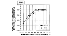
- Le determines the range of the central part of the steel pipe, and is the distance from the end of the steel pipe/the outer diameter at that position, the longitudinal ellipticity of the cross section at the outer diameter measurement position, and the length of the steel pipe in the pipe forming direction. It is a figure showing the relationship of the difference of the vertical ellipticity of the 1/2 position.
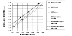
- the steel pipe has an outer diameter of 114.3 mm, a wall thickness of 3.5 mm, and a length of 7,400 mm. It is a figure showing the tensile strength of a steel pipe, and the relation of longitudinal ellipticity ( ⁇ DE) of a steel pipe end-vertical ellipticity ( ⁇ DC) of a steel pipe central part.
- the steel pipe has an outer diameter of 114.3 mm and a wall thickness of 3.2 to 8.6 mm. It is a figure showing the tensile strength of a steel pipe for every plate thickness, and the relation of longitudinal ellipticity (deltaDE) of a steel pipe end-vertical ellipticity (deltaDC) of a steel pipe central part.
- the outer diameter of the steel pipe is 114.3 mm. It is a figure showing the relationship between the tensile strength of a steel pipe and the standard deviation of the average outer diameter of a steel pipe center part.
- the steel pipe has an outer diameter of 114.3 mm and a wall thickness of 3.2 to 8.6 mm.
- the outer diameter of the steel pipe is 114.3 mm. It is a figure which shows the relationship of the tensile strength of a steel pipe and the residual stress of a steel pipe center part.
- the steel pipe has an outer diameter of 114.3 mm and a wall thickness of 3.2 to 8.6 mm. It is the figure which showed typically the change of the average outer diameter of a steel pipe end when a steel pipe end deform
- FIG. 1 shows the vertical ellipticity (DELTA)DC of the central part (before cutting) of a steel pipe, and the vertical ellipticity (DELTA)DE of a steel pipe end (after cutting) when joining a steel pipe end by fitting.
- DELTA vertical ellipticity
- DELTA vertical ellipticity
- the inventors measured the steel pipe cross-sectional dimension of the steel pipe central portion before and after cutting when the steel pipe central portion was cut to a predetermined length after pipe making, and the steel pipe cross-sectional dimension due to the residual stress being released by the steel pipe cutting.
- the changes in the above were investigated in detail.
- the cross-sectional shape of the steel pipe before cutting is achieved by adjusting the roll position of each roll stand in the pipe forming step, welding step, and straightening step.
- the manufacturing conditions cannot be unconditionally specified because each process condition is slightly different depending on the specifications of the pipe making equipment, such as the number of roll stages, the rolling force, the roll profile and their arrangement. It can be carried out by finding and adjusting the process conditions suitable for the pipe making equipment by appropriately measuring the dimensions and confirming the roundness after the pipe making. Most of the steel pipes are cut by sawing, but may be cut by a lathe. In the present specification, the "high-strength electric resistance welded steel pipe" may be simply referred to as "steel pipe”. Further, in the present specification, the numerical range represented by “to” means a range including the numerical values before and after “to” as the lower limit value and the upper limit value.
- the high-strength electric resistance welded steel pipe according to the present embodiment has C: 0.04 to 0.30%, Si: 0.01 to 2.00%, Mn: 0.50 to 3.00% in mass% or mass ppm.
- the outer diameter (DCave described later) of the steel pipe is 60.3 mm or more and 318.5 mm or less.
- the outer diameter of the steel pipe is 60.3 mm or more, the strength of the steel pipe as the object of the present invention is easily obtained. If the outer diameter of the steel pipe is 318.5 mm or less, it is easy to carry.
- the outer diameter of the steel pipe is preferably 113 mm or more and 116 mm or less.
- the outer diameter of the steel pipe is an average outer diameter.
- the ratio (tCave/DCave) between the wall thickness of the steel pipe (tCave described below) and the outer diameter of the steel pipe (DCave described below) is 0.02 or more and 0.06 or less. When the ratio (tCave/DCave) between the wall thickness of the steel pipe and the outer diameter of the steel pipe is 0.02 or more, the strength of the steel pipe is easily achieved.
- the tensile strength of the steel pipe is 590 N/mm 2 or more. When the tensile strength is 590 N/mm 2 or more, the wall thickness can be reduced and the weight can be easily carried by hand.
- the tensile strength is preferably 780 N/mm 2 or more.
- Tensile strength is preferably 1200 N / mm 2, more preferably not more than 1500 N / mm 2.
- the yield ratio of the steel pipe is preferably 86% or more and 99% or less because the joint strength of the screw increases.
- the tensile strength and the yield ratio of the steel pipe can be obtained by taking a full-thickness test piece in the pipe axial direction from the base material portion of the steel pipe after pipe making and performing a tensile test in the pipe axial direction.
- the welded portion is placed at 12 o'clock of the timepiece, its position is 0°, an arbitrary outer diameter within a range of ⁇ 45° is D1, and a diameter orthogonal to D1 is D3.
- the diameter at a position of 45° clockwise from D1 is D2, and the diameter at a position of 45° clockwise from D3 is D4.
- the outer diameters of the steel pipe central portions in D1, D2, D3, and D4 are DC1, DC2, DC3, and DC4, respectively, and the average thereof is the average outer diameter of the steel pipe central portion and is called DCave.
- the inner diameters of the central portions of the steel pipes at the positions D1, D2, D3, D4 are respectively dC1, dC2, dC3, dC4, and the average thereof is referred to as the average inner diameter of the central portions of the steel pipes, dCave, and D1, D2, D3, D4.
- the thickness of the central portion of the steel pipe at the position of is defined as tC1, tC2, tC3, and tC4, and the average thereof is defined as the average thickness of the central portion of the steel pipe, which is referred to as tCave.
- the units of DC1, DC2, DC3, DC4, dC1, dC2, dC3, dC4, tC1, tC2, tC3, tC4, DCave, dCave, and tCave are all mm.
- the welded portion is placed at 12 o'clock and its position is set to 0°, and an arbitrary outer diameter within a range of ⁇ 45° is set to D1, and a diameter orthogonal to D1 is set to D3. ..
- the diameter at a position of 45° clockwise from D1 is D2, and the diameter at a position of 45° clockwise from D3 is D4.
- the outer diameters of the steel pipe ends in D1, D2, D3, and D4 are DE1, DE2, DE3, and DE4, and the average thereof is the average outer diameter of the steel pipe ends and is called DEave.
- the inner diameters of the steel pipe ends at the positions of D1, D2, D3, D4 are dE1, dE2, dE3, dE4, and the average thereof is the average inner diameter of the steel pipe ends, dEave, and the steel pipes at the positions of D1, D2, D3, D4.
- the wall thicknesses of the end portions are tE1, tE2, tE3, and tE4, and the average thereof is the average wall thickness of the steel pipe end portion and is called tEave.
- the units of DE1, DE2, DE3, DE4, dE1, dE2, dE3, dE4, tE1, tE2, tE3, tE4, DEave, dEave, and tEave are all mm.
- the part separated to the side is the central part of the steel pipe.
- the central portion of the steel pipe is a range in which the residual stress generated during pipe forming is released when the steel pipe is cut, and the cross-sectional dimension of the steel pipe is deformed.
- An example thereof is shown in FIG.
- the horizontal axis of FIG. 1 is “distance from steel pipe end/outer diameter at that position”.
- the vertical axis represents the “difference between the vertical ellipticity of the cross section at the outer diameter measurement position and the vertical ellipticity of the length 1/2 position in the pipe forming direction”.
- the distance from the steel pipe end/outer diameter at that position” on the horizontal axis is greater than 1.0, that is, the distance from the cutting position of the steel pipe end is the outer diameter of the steel pipe toward the center in the longitudinal direction of the steel pipe.
- the distance from the center of the steel pipe is larger than the position Le, that is, at the center of the steel pipe before cutting, "vertical ellipticity of the cross section at the outer diameter measurement position and vertical ellipse at a position of 1/2 length in the length direction of the steel pipe"
- the difference in degree" is almost 0, which means that the longitudinal ellipticity is the same with respect to the 1/2 position in the length direction of the steel pipe and the steel pipe is not deformed.
- the horizontal axis is 1.0 or less, that is, the steel pipe end portion side from the position Le distant from the cutting position of the steel pipe end portion by the outer diameter of the steel pipe toward the central portion in the longitudinal direction of the steel pipe is “outer diameter”.
- the difference between the vertical ellipticity of the cross section at the measurement position and the vertical ellipticity at the 1/2 position in the pipe-making direction fluctuates in the negative direction. This means that when the steel pipe is cut into the steel pipe end, the residual stress is released, the deformation of the steel pipe end increases, and the roundness deteriorates.
- the cutting position of the steel pipe is the position cut for product collection in the middle of pipe making, at both ends of the steel pipe product at the time of shipping after pipe making, at an intermediate company, or at the construction site of the construction site. It also includes the ends of steel pipes obtained by cutting.
- K is a constant calculated by the following equation (6).
- K ⁇ +( ⁇ /I)+( ⁇ TS) ⁇ DCave (6)
- TS is the tensile strength (N/mm 2 ) of the steel pipe base material
- ⁇ , ⁇ and ⁇ are constants
- ⁇ -1.87 ⁇ 10 ⁇ 3
- ⁇ 1.35 ⁇ 10 4
- ⁇ ⁇ 6.65 ⁇ 10 ⁇ 6
- I is the second moment of area (mm 4 ) of the cross section of the central portion of the steel pipe, and is derived by the following equation (12).
- I ⁇ /64 ⁇ (DCave) 4 ⁇ (DCave-2 ⁇ tCave) 4 ⁇ (12)
- FIG. 3 shows an example of the calculation result of the equation (21) for each plate thickness.
- Standard deviation of the average outer diameter of the central portion of the steel pipe ⁇ p+(q/I)+(r ⁇ TS) ⁇ DCave ( 8)
- TS is the tensile strength (N/mm 2 ) of the steel pipe base material
- p, q, and r are constants
- p 1.39 ⁇ 10 ⁇ 3
- q 4.17 ⁇ 10 2
- r It is 6.05 ⁇ 10 ⁇ 7
- I is the second moment of area (mm 4 ) of the cross section of the central portion of the steel pipe, which is derived from the above-mentioned equation (12).
- FIG. 5 shows an example of the calculation result of the formula (8) for each plate thickness.
- the steel pipe for the said use has two usage methods when connecting and using a plurality of steel pipes.
- One is a method in which male and female threads are directly threaded on both ends of a steel pipe using a rotary cutting device and the steel pipes are connected and used.
- the other is that one or more jigs are used between the steel pipes. It is a method of fitting and connecting to the end of the steel pipe.
- the steel pipe end part is also provided with one or more jigs between the steel pipes.
- the fitting method in order to secure the strength on the fitting surface, it is necessary to secure a high roundness as well as the outer diameter tolerance of the steel pipe at the pipe end.
- the higher the strength the higher the strength of the steel pipe. Has a high residual stress.
- the residual stress is released to the end of the steel pipe near the cutting position, the force of deformation acts, and the thin wall is more likely to be deformed, and the change in longitudinal ellipticity at the pipe end tends to be large. Securing becomes an issue.
- the residual stress is measured by the Crumpton method (for example, described in Nippon Steel & Sumikin Technical Report No. 397 (2013) p31).
- Fig. 7 shows that when threading is directly performed on the end of the steel pipe, the cross section becomes vertically long (vertical ellipticity> 0) compared to the case where the design values of threading, that is, the outer diameter and the wall thickness are average values.
- both male and female threads have a residual portion that is not cut with respect to the average wall thickness. It is necessary to make the residual thickness as small as possible while ensuring the soundness and soundness of the screw shape, and it is required to set the vertical ellipticity of the steel pipe end within a certain range.
- the inventors clarified the relationship between the longitudinal ellipticity of the central portion of the steel pipe and the longitudinal ellipticity of the steel pipe end when the tensile strength and the size are different, based on the above new knowledge, that is, the steel pipe has a predetermined length L.
- a method has been found in which the steel pipe end portion after cutting the steel pipe has a high roundness by setting the longitudinal ellipticity of the central portion and the steel pipe end portion after cutting within a predetermined range.
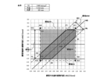
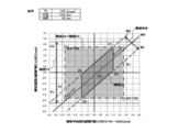
- an area AA is an area required to secure the outer diameter tolerance, and is an area surrounded by points A1, A2, A3, and A4 in FIG.
- the outer diameter tolerance (tolerance 1) ⁇ 1% specified by JIS G 3444 (2016) structural steel pipe is satisfied.
- the outer diameter tolerance may be changed according to the standard. This range is a necessary condition to secure the necessary circular shape when used as a structural pipe.If this is not satisfied, the bending moment required for the structural steel pipe is secured and the bending obtained from it. Proof strength and buckling resistance cannot be maintained. This range is a range necessary to ensure the function as a structural pipe.
- points A1 to A4 satisfy the following expressions (24) to (31).
- Point A2: x(A2) DCave ⁇ (2/100) (26)
- y(A2) DEave ⁇ ( ⁇ 2/100)
- Point A3: x(A3) DCave ⁇ ( ⁇ 2/100) (28)
- y(A3) DEave ⁇ ( ⁇ 2/100)
- Point A4: x(A4) DCave ⁇ ( ⁇ 2/100) (30)
- y(A4) DEave ⁇ (2/100) (31)
- the area AA is (x, y) that simultaneously satisfies the following expressions (32) and (33).
- the region YY is the range of the shape of the pipe end that should be secured in order to secure the necessary screw function while reducing the residual thickness as much as possible in the thread cutting process to reduce the weight of the steel pipe.
- the inventors have calculated the average residual thickness schematically shown in FIG. Average remaining meat ⁇ tEave/3 (34) I found that. If the residual thickness is less than this, it is considered that the joint strength required for the tubular body cannot be ensured, and the function as the original application such as breakage of the joint portion during use cannot be ensured.
- the residual thickness limit is Marginal residual thickness ⁇ 0.65 mm (35) I found that. If this value is less than this value, there will be problems in manufacturing and usage, such as an increase in manufacturing cost due to defective products due to deformation of the screw part during processing, and inability to use due to deformation of the screw part during product use. There are cases.
- Fig. 7 shows an example of the conditions necessary for the shape of the pipe end to be secured in order to secure the necessary screw function while reducing the residual thickness as much as possible in the thread cutting process to reduce the weight of the steel pipe.
- the male screw side is the following formula (36)
- Marginal residual meat Average residual meat-(dE1-dEave)/2 ⁇ 0.65 (36)
- dEave DEave-2 ⁇ tEave (38) Is.
- the equation (40) becomes the following equation (41), DEave-DE3 ⁇ 2 ⁇ (tEave/3)-0.65 ⁇ (41)
- the male screw side has the following formula (43), DEave-DE1 ⁇ 2 ⁇ (tEave/3)-0.65 ⁇ (43)
- the female screw side has the following formula (44), DE3-DEave ⁇ 2 ⁇ (tEave/3)-0.65 ⁇ (44)
- the following equation (45) DE3-DE1 ⁇ 4 ⁇ (tEave/3)-0.65 ⁇ (45)
- Rewriting equation (45), the following equation (46) ⁇ DE DE1-DE3 ⁇ 4 ⁇ (tEave/3) ⁇ 0.65 ⁇ (46) Becomes
- the x-axis is the vertical ellipticity ⁇ DC of the central portion of the steel pipe
- the y-axis is the vertical ellipticity ⁇ DE of the steel pipe end portion.
- the x-axis component of the point i in the figures is x(i)
- the axis component is expressed as y(i).
- MAX(n,m) represents the larger value of n and m
- MIN(n,m) represents the smaller value of n and m.
- (x, y) that simultaneously satisfies the following formulas (49) and (50) is the region YY. - ⁇ x ⁇ (49) ⁇ 4 ⁇ (tEave/3) ⁇ 0.65 ⁇ y ⁇ 4 ⁇ (tEave/3) ⁇ 0.65 ⁇ (50)
- Region XX which is commonly surrounded by region AA and region YY, that is, the outer diameter tolerance for ensuring the function as a structural pipe is secured, the residual thickness is made as small as possible, and the weight of the steel pipe is reduced, while the required screw
- the region where the function can be secured is the region surrounded by the points X1, X2, X3, and X4, and is expressed by the following equations (51) to (58).
- YN and YM are not shown in FIG. 8, but are as follows.
- the larger value is -0.65.
- .65 is the smaller value, and is the equation (4) and the equation (5).
- YN MAX[ ⁇ DEave ⁇ ( ⁇ 2/100) ⁇ , ⁇ -4 ⁇ ((tEave/3) ⁇ 0.65) ⁇ ]
- YM MIN[ ⁇ DEave ⁇ (2/100) ⁇ , ⁇ 4 ⁇ ((tEave/3) ⁇ 0.65) ⁇ ] (4)
- the inventors clarified the relationship between the central ellipticity of the steel pipe and the longitudinal ellipticity of the steel pipe end as described above, and using this, control the longitudinal ellipticity of the central part of the steel pipe in a certain range in pipe making.
- a method has been found in which the longitudinal ellipticity of the steel pipe end portion after the steel pipe is cut is ensured to be low and thread cutting is possible.
- the method and the area of the product obtained by the method are shown as area PP in FIG. 8 below.
- the region PP is a region in which the above-mentioned region XX and the below-described region WW are overlapped.
- the region WW indicates the range of ⁇ DC and ⁇ DE obtained by manufacturing using the relationship between the longitudinal ellipticity of the central portion of the steel pipe and the longitudinal ellipticity of the steel pipe, including variations.
- the area WW in FIG. 8 will be described.
- y is ⁇ DE and x is ⁇ DC, and when replaced with this, the above-mentioned expression (21) is obtained.
- K is a constant obtained by the above equation (6).
- the standard deviation of the average outer diameter DCave of the central portion of the steel pipe obtained by the above equation (8) is used.
- the region WW is surrounded by WH and the line WL.
- WH represents the upper limit of ⁇ DE which is +3 ⁇ from the average
- WL represents the lower limit of ⁇ DE which is ⁇ 3 ⁇ from the average, and are represented by the following formulas (63) and (64).
- the region PP of FIG. It is the range of possible products, and is the overlapping portion of region XX and region WW.
- the region PP is (x, y) that simultaneously satisfies the following formulas (59), (60) and (3).
- Point P1 An intersection of a line passing through X1 and X2 and a line WL.
- Point P2 An intersection of a line passing through X4 and X3 and a line WH.
- Point Z1 An intersection of a line passing through X4 and X1 and a line WH.
- Point Z3 An intersection of a line passing through X3 and X2 and a line WL.
- the region XX may not be satisfied due to manufacturing variations. Therefore, in the thread cutting process, the range of ⁇ DC to be set in FIG. 9 and the range of ⁇ DE obtained at that time are defined as a more preferable region in which it is possible to stably secure the region XX in consideration of manufacturing variations. Shown as ZZ. Expressed by the formula, the region (ZZ) satisfies the following formula (65) and the formula (3) at the same time. YN-K+3 ⁇ SD ⁇ x ⁇ YM-K-3 ⁇ SD (65) x+K-3 ⁇ SD ⁇ y ⁇ x+K+3 ⁇ SD (3) When this is shown by coordinates in FIG.
- the area ZZ is an area that satisfies the area XX and is surrounded by a line connecting the following four points, point Z1, point Z2, point Z3, and point Z4.
- Point Z1 An intersection of a line passing through X4 and X1 and a line WH, and is represented by the following equations (66) and (67).
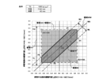
- the region YY (the region necessary to secure the necessary screw function while reducing the residual wall as much as possible in the thread cutting process to reduce the weight of the steel pipe) becomes the area AA. It may be larger than (the range required to secure the outer diameter tolerance), and the region PP in that case is shown in FIG.
- the area XX which is the overlap of the area AA and the area YY, is the same as the area AA.
- (x, y) that simultaneously satisfies the following equations (32) and (33) is the region XX and is represented by the following equations (32) and (33).
- the area XX is an area inside the line connecting the following four points X1, X2, X3, and X4, and the following equations (24) to (31) It is expressed by a formula.
- the region WW showing the range of ⁇ DC and ⁇ DE obtained when manufacturing is performed by using the relationship between the vertical ellipticity of the steel pipe central portion and the steel pipe end portion is the same as the above description.
- (X, y) that simultaneously satisfies the above-described expression (3) is the region WW and is expressed by the following expression (3).
- a region PP is a portion where the region XX and the region WW overlap.
- the region PP is (x, y) that simultaneously satisfies the following equations (32), (33) and (3).
- Point P1 An intersection of a line passing through X1 and X2 and a line WL.
- Point P2 An intersection of a line passing through X4 and X3 and a line WH.
- Point Z1 An intersection of a line passing through X4 and X1 and a line WH.
- Point Z3 An intersection of a line passing through X3 and X2 and a line WL.
- FIG. 11 shows a region ZZ which is a more preferable region in which it is possible to stably secure the region XX in consideration of manufacturing variations in this case.
- the area ZZ is an area inside the line connecting the following four points Z1, Z2, Z3, and Z4, which satisfies the area XX and is defined by the following (75 ) To (82).
- Point Z1 An intersection of a line passing through X4 and X1 and a line WH.
- Point Z4: An intersection of x x(Z3) and the line WH.
- the vertical ellipticity of the central portion of the steel pipe is controlled in a certain range in pipe making by using the relationship between the vertical ellipticity of the central portion of the steel pipe and the vertical ellipticity of the end portion of the steel pipe in pipe making.
- a region PP which is a product region obtained by a method of ensuring a low ellipticity, is a portion where the region XX and the region WW overlap. Expressed by an equation, the region PP is (x, y) that simultaneously satisfies the following equations (32), (33) and (3).
- FIG. 13 shows a case where the steel pipe ends are fitted and connected to each other via one or a plurality of jigs to be used by being connected to each other in consideration of manufacturing variations, and the region XX is stably provided.
- a more preferable region ZZ in which the above can be secured is shown.
- the area ZZ is an area that satisfies the area XX and is surrounded by a line connecting the following four points, the point Z1, the point Z2, the point Z3, and the point Z4. It is represented by equations (82).
- Point Z1 An intersection of a line passing through X4 and X1 and a line WH.
- Point Z4: An intersection of x x(Z3) and the line WH.
- the hot-rolled steel sheet used for the high-strength electric resistance welded steel pipe is manufactured by heating the steel having the above-mentioned components, hot rolling, controlled cooling, and winding.
- the heating temperature of steel is preferably 1150° C. or higher in order to solid-dissolve carbide forming elements such as Nb in the steel.
- the heating temperature is too high, the austenite grains become coarse, and as a result, the ferrite grain size becomes coarse, so 1280° C. or lower is preferable.
- the finishing temperature of hot rolling is preferably 850° C.
- the obtained hot-rolled steel sheet is continuously formed into an open pipe by roll forming, and then the end portions of the open pipe are butted to each other by electric resistance welding to manufacture an electric resistance welded steel pipe. Seam heat treatment for heating the electric resistance welded portion and accelerating cooling may be performed. After that, the outer diameter of the steel pipe may be reduced by 0.5% to 4.0% with a sizer.
- Fig. 14 shows an example of the manufacturing process for ERW steel pipe.
- ERW steel pipe is manufactured by cold working with multiple roll stands, forming process to bend steel sheet into C section, welding process to sew the pipe end, and straightening process to adjust the shape by slightly reducing the pipe diameter.
- the AA' cross section is the stand position of the welding process
- the BB' cross section is one of the stand positions of one or more straightening processes
- the CC' cross section is the center position of the roll at the final stage of the straightening process.
- a cross section taken at a position larger than the position Le from the cut position a DD′ cross section, is the steel pipe end.
- the pipe width and pipe height in each cross section are Ah, Av, Bh, Bv, D1 (steel pipe central portion), D3 (steel pipe central portion), D1 (steel pipe end portion), D3 (steel pipe end portion) (mm).
- the pipe width is the pipe outer surface distance between 90° and 270°
- the pipe height is the pipe outer surface distance between 0° and 180° when the electric resistance weld is at the 0° position.
- the upper, lower, and width rolls of the welding stand be adjusted appropriately so that the pipe width Ah and pipe height Av of the AA' cross section have appropriate values?
- the upper, lower, and width rolls of the final stage of the straightening stand may be appropriately adjusted to set the tube width Bh and the tube height Bv of the BB' section to appropriate values.
- the former staking is preferable.
- the steel pipe is work-hardened for the purpose of further increasing the strength, the latter method is preferable.
- the manufacturing process of the electric steel pipe is not limited to the case of FIG. 14, but the number of rolls, the number of stages, and the shape are different, and therefore, the manufacturing conditions that satisfy the conditions of the present invention are searched for in each facility.
- the fitting part in the method of fitting and connecting the steel pipe ends to the steel pipe ends through one or a plurality of jigs between the steel pipes, the fitting part is welded, bonded or mechanically. It also includes the case where the steel pipe and the jig are firmly joined by various joining (for example, screwing, fitting using the elasticity of the material, pinning, etc.).
- the "jigs" are couplings and nipples, and the couplings and nipples are joined to the steel pipe by welding or mechanical joining, instead of directly cutting the screws into the steel pipe.
- the length of the high-strength electric resistance welded steel pipe according to the present invention is preferably 2000 mm to 5000 mm as described above, and more preferably 3000 mm to 3500 mm which is a commonly used length.
- the composition of the high strength ERW steel pipe according to the present embodiment will be described.
- content simply means the content in the steel pipe.
- the steel pipe of this embodiment has C: 0.04 to 0.30%, Si: 0.01 to 2.00%, Mn: 0.50 to 3.00% in mass% or mass ppm. , P: 0.030% or less, S: 0.030% or less, Al: 0.005 to 0.700%, N: 100 ppm or less, Nb: 0 to 0.100%, V: 0 to 0.100% , Ti:0 to 0.200%, Ni:0 to 1.000%, Cu:0 to 1.000%, Cr:0 to 1.000%, Mo:0 to 1.000%, B:0 to It contains 50 ppm, Ca: 0 to 100 ppm and REM: 0 to 200 ppm, the balance being iron and impurities.
- each element, content, and impurities will be described.
- C is an element effective in improving the strength of the steel pipe.
- the content of C in the steel pipe of the present invention is 0.04% or more. As a result, the strength of the hot-rolled steel sheet and consequently the strength of the steel pipe are secured. On the other hand, if the content of C is too large, the strength of the steel pipe becomes too high and the toughness deteriorates. Therefore, the upper limit of the C content is 0.30%.
- the upper limit of the C content is preferably 0.25%, more preferably 0.20%.
- Si silicon
- Si silicon
- the Si content is preferably 1.20% or less, and more preferably 0.60% or less.
- the content of Si is 0.01% or more from the viewpoint that the effect as a deoxidizer can be obtained more effectively.
- the content of Si is preferably 0.10% or more, and more preferably 0.20% or more from the viewpoint that the strength of the steel pipe is further enhanced by solid solution strengthening.
- Mn manganese
- Mn (manganese) is an element that increases the strength of steel by enhancing the hardenability of steel.
- the content of Mn (manganese) in the steel pipe of the present invention is 0.50% or more from the viewpoint of ensuring high strength.
- the Mn content is preferably 0.80% or more.
- the upper limit of the Mn content is 3.00%. In order to obtain higher toughness, the upper limit is preferably 2.00%.
- P phosphorus
- the upper limit of the P content is 0.030%.
- the P content is preferably 0.020% or less. Since it is preferable that the content of P is small, the lower limit of the content of P is not particularly limited. However, the P content is usually 0.001% or more from the viewpoint of the balance between the characteristics and the cost.
- S sulfur
- S is an impurity.
- the content of S is preferably 0.020% or less, more preferably 0.010% or less. Since it is preferable that the content of S is small, the lower limit of the content of S is not particularly limited. However, the content of S is usually 0.001% or more from the viewpoint of the balance between characteristics and cost.
- Al 0.005 to 0.700%>
- Al (aluminum) is an element effective as a deoxidizing agent.
- the upper limit of the Al content is 0.700%.
- the content of Al is 0.005% or more from the viewpoint of more effectively obtaining the effect as the deoxidizer.
- the upper limit is preferably 0.100% or less.
- N nitrogen
- the upper limit of the N content is 100 ppm.
- the content of N is preferably 80 ppm or less, particularly preferably 60 ppm or less.
- the lower limit of the content of N is not particularly limited, the content of N is preferably 10 ppm or more in consideration of the cost and economic efficiency of N removal (denitrification).
- Nb niobium
- the Nb content is preferably 0.06% or less, more preferably 0.05% or less.
- the content of Nb is preferably 0.010% or more, particularly preferably 0.020% or more, from the viewpoint of more reliably obtaining the effect of refining the structure.
- V vanadium
- the V content is more preferably 0.060% or less.
- the V content is preferably 0.010% or more.
- Ti titanium
- TiN fine nitride
- the content of Ti is 0 to 0.200%.
- the Ti content is more preferably 0.100% or less, and particularly preferably 0.050% or less.
- the content of Ti is preferably 0.010% or more, and more preferably 0.015% or more, from the viewpoint of further improving the toughness by refining the structure.
- Ni nickel
- Ni nickel
- Ni is an element that enhances the strength of steel by enhancing the hardenability of steel.
- Ni is also an element that contributes to the improvement of toughness.
- the Ni content is 0 to 1.000% from the economical point of view.
- the Ni content is more preferably 0.500% or less.
- the Ni content is preferably 0.100% or more.
- Cu (copper) is an element that enhances the strength of steel by enhancing the hardenability of steel. Cu is also an element that contributes to solid solution strengthening. However, if the Cu content is too high, the surface properties of the steel pipe may be impaired. Therefore, the Cu content is 0 to 1.000%. The Cu content is more preferably 0.500% or less. On the other hand, the Cu content is preferably 0.100% or more. When the steel pipe contains Cu, it is preferable to simultaneously contain Ni from the viewpoint of preventing the deterioration of surface properties.
- Cr chromium
- Cr is an element effective in improving strength.
- the Cr content is more preferably 0.500% or less.
- the Cr content is preferably 0.100% or more.
- Mo molybdenum
- Mo molybdenum
- the content of Mo is more preferably 0.500% or less, and particularly preferably 0.300% or less.
- the Mo content is preferably 0.050% or more.
- B boron
- the upper limit of the content of B is Is 50 ppm.
- the content of B is preferably 3 ppm or more in order to sufficiently obtain the effect of hardenability.
- Ca (calcium) is an element that controls the morphology of sulfide inclusions, improves the low temperature toughness, and further refines the oxide of the electric resistance welded portion to improve the toughness of the electric resistance welded portion.
- the content of Ca is 0 to 100 ppm.
- the content of Ca is preferably 10 ppm or more.
- REM means a rare earth element, and Sc (scandium), Y (yttrium), La (lanthanum), Ce (cerium), Pr (praseodymium), Nd (neodymium), Pm (promethium). ), Sm (samarium), Eu (europium), Gd (gadolinium), Tb (terbium), Dy (dysprosium), Ho (holmium), Er (erbium), Tm (thulium), Yb (ytterbium), and Lu (lu). Lutetium) is a general term for 17 kinds of elements.
- REM 0 to 200 ppm
- REM is an element that controls the morphology of sulfide-based inclusions, improves low temperature toughness, and further refines the oxide of the electric resistance welded portion to improve the toughness of the electric resistance welded portion.
- the content of REM is preferably 0 to 200 ppm.
- the content of REM is preferably 10 ppm or more.
- the impurity means a component contained in the raw material or a component mixed in the manufacturing process and not intentionally contained in the steel.
- impurities specifically, O (oxygen), Sb (antimony), Sn (tin), W (tungsten), Co (cobalt), As (arsenic), Mg (magnesium), Pb (lead), Bi( Bismuth) and H (hydrogen). Of these, it is preferable to control the content of O to be 0.004% or less.
- the method of using the high-strength electric resistance welded steel pipe for ground stabilization work of the present invention is to perform thread cutting on a new steel pipe end portion generated by cutting at the steel pipe central portion of the above-mentioned high strength electric resistance welded steel pipe, and use two screw joints.
- the above high strength ERW steel pipes are connected and used.
- the method of using the high-strength electric resistance welded steel pipe for ground stabilization work of the present invention is a new steel pipe end portion generated by cutting one or both of the steel pipe end portions of the above-mentioned high-strength electric resistance welded steel pipe at the central portion of the steel pipe. Then, two or more high-strength electric resistance welded steel pipes are connected to each other by fitting the ends of the steel pipes via one or a plurality of jigs.
- the table of examples shows the conditions and results of examples and comparative examples under each condition.
- “G” of each area indicates that each area can be satisfied
- “NG” of each area indicates that each area cannot be satisfied.
- the required outer diameter tolerance cannot be ensured at both the steel pipe end portion and the steel pipe center portion. This can be determined by measuring the outer diameter of the steel pipe. In this case, when it is used as a structural pipe, the necessary circular shape cannot be secured, so the required bending moment or bending proof strength cannot be secured, and deformation and buckling occur during use, and the function required as a structural pipe is not obtained. I'm not satisfied.
- the residual thickness required for the screw cannot be secured, deformation may occur during screw processing, and the screw function such as poor connection cannot be secured during use. This can be determined visually by measuring the dimensions with a screw gauge or the like. Also, as the tubular body, it is not possible to secure the necessary residual thickness, so the strength of the joint cannot be secured, and when used, deformation such as bending of the joint part, breakage, etc. occur, and the function as the original application can be secured. Can not. This can be visually determined.
- the region WW is not satisfied, the operation results deviate from the relationship between the vertical ellipticity of the central portion of the steel pipe and the end portion of the steel pipe obtained by the present invention, and correct molding cannot be performed.
- the product is not manufactured correctly due to a local defect in the shape of the product or an abnormality in the equipment.Because a certain quality is not obtained in the manufacturing lot, it cannot be a product. Can not. This can be determined by visual inspection of the product or inspection of the equipment.
- the region WW is not satisfied, the steel pipe required for threading cannot be shaped because the correct forming is not performed, so deformation may occur during threading and the screw function such as connection failure during use. Cannot be ensured, and since the outer diameter tolerance cannot be ensured as a constant value in the manufacturing lot, they cannot be satisfied. In order to carry out the thread machining without deformation and to secure the outer diameter tolerance, it is necessary to secure the region WW.
- the thread processing state and the ensuring of the steel pipe outer diameter tolerance are shown.
- Securing the outer diameter tolerance of the steel pipe means that both the end portion of the steel pipe and the central portion of the steel pipe satisfy the outer diameter tolerance.
- the area WW which is a condition that correct molding is performed and a certain quality is ensured as a steel pipe product, is satisfied
- the area YY that is a condition that can secure a necessary residual thickness as a screw can be simultaneously satisfied. Very good threading is possible.
- the region WW which is a condition that correct molding is performed and a certain quality as a steel pipe product is secured
- the region AA which is a condition that the outer diameter tolerance is secured
- the region PP cannot be satisfied, that is, either one or both of the region XX and the region WW cannot be satisfied, and in that case, a defect that cannot be satisfied with each occurs.
- the region XX is not satisfied, the residual thickness required for the screw cannot be secured, deformation may occur during screw processing, and the screw function such as connection failure cannot be secured during use.
- the region WW is not satisfied, correct forming is not performed, so the shape of the steel pipe required for threading cannot be formed, so deformation may occur during threading, and the function of the screw such as connection failure during use may occur. Cannot be secured.
- the outer diameter tolerance cannot be ensured as a constant value in the manufacturing lot, so that the outer diameter tolerance cannot be satisfied.
- the area ZZ is the range of the better embodiment, and even if the area ZZ is out of the area XX and the range of WW, it is the embodiment.
- the use of a high-strength electric resistance welded steel pipe which is lightweight and has high strength and whose steel pipe end portion generated by new cutting after pipe fabrication has high circularity and a ground stabilization work high strength electric resistance welded steel pipe A method can be provided. Therefore, the industrial applicability is great.
Landscapes
- Chemical & Material Sciences (AREA)
- Engineering & Computer Science (AREA)
- Materials Engineering (AREA)
- Mechanical Engineering (AREA)
- Metallurgy (AREA)
- Organic Chemistry (AREA)
- Physics & Mathematics (AREA)
- Thermal Sciences (AREA)
- Crystallography & Structural Chemistry (AREA)
- Structural Engineering (AREA)
- Life Sciences & Earth Sciences (AREA)
- General Life Sciences & Earth Sciences (AREA)
- Mining & Mineral Resources (AREA)
- Paleontology (AREA)
- Civil Engineering (AREA)
- General Engineering & Computer Science (AREA)
- Rigid Pipes And Flexible Pipes (AREA)
- Piles And Underground Anchors (AREA)
- Heat Treatment Of Articles (AREA)
Abstract
L'invention concerne un tuyau en acier à haute résistance soudé par résistance électrique tel que : le diamètre externe du tube en acier mesure de 60,3 à 318,5 mm inclus ; le rapport de l'épaisseur de paroi du tube en acier et du diamètre externe du tube en acier va de 0,02 à 0,06 inclus ; la résistance à la traction est supérieure ou égale à 590 N/mm2 ; et lorsqu'une partie centrale du tube en acier est coupée, des plages de valeurs numériques spécifiques sont satisfaites en des emplacements prescrits.
Priority Applications (3)
| Application Number | Priority Date | Filing Date | Title |
|---|---|---|---|
| MYPI2021004238A MY205932A (en) | 2019-02-21 | 2020-02-21 | High-strength electric-resistance-welded steel pipe and method for using high-strength electric-resistance-welded steel pipe in construction work to stabilize foundation |
| CN202080014708.6A CN113423846B (zh) | 2019-02-21 | 2020-02-21 | 高强度电焊钢管和地基稳定化工程用高强度电焊钢管的使用方法 |
| JP2020564021A JP6841392B2 (ja) | 2019-02-21 | 2020-02-21 | 高強度電縫鋼管および地盤安定化工事用高強度電縫鋼管の使用方法 |
Applications Claiming Priority (2)
| Application Number | Priority Date | Filing Date | Title |
|---|---|---|---|
| JP2019-029437 | 2019-02-21 | ||
| JP2019029437 | 2019-02-21 |
Publications (1)
| Publication Number | Publication Date |
|---|---|
| WO2020171209A1 true WO2020171209A1 (fr) | 2020-08-27 |
Family
ID=72144899
Family Applications (1)
| Application Number | Title | Priority Date | Filing Date |
|---|---|---|---|
| PCT/JP2020/007101 Ceased WO2020171209A1 (fr) | 2019-02-21 | 2020-02-21 | Tuyau en acier à haute résistance soudé par résistance électrique, et procédé d'utilisation d'un tuyau en acier à haute résistance soudé par résistance électrique sur un chantier de construction pour stabiliser des fondations |
Country Status (4)
| Country | Link |
|---|---|
| JP (1) | JP6841392B2 (fr) |
| CN (1) | CN113423846B (fr) |
| MY (1) | MY205932A (fr) |
| WO (1) | WO2020171209A1 (fr) |
Cited By (1)
| Publication number | Priority date | Publication date | Assignee | Title |
|---|---|---|---|---|
| JP2024545450A (ja) * | 2021-12-16 | 2024-12-06 | ポスコ カンパニー リミテッド | 地盤補強用熱延鋼板及び鋼管とこれらの製造方法 |
Citations (6)
| Publication number | Priority date | Publication date | Assignee | Title |
|---|---|---|---|---|
| WO2012133558A1 (fr) * | 2011-03-30 | 2012-10-04 | 新日本製鐵株式会社 | Tuyau d'acier électrosoudé longitudinalement et son procédé de production |
| WO2015022899A1 (fr) * | 2013-08-16 | 2015-02-19 | 新日鐵住金株式会社 | Tuyau en acier soudé par résistance électrique présentant une excellente qualité de soudure, et procédé permettant de produire ledit tuyau |
| JP2016047956A (ja) * | 2014-08-28 | 2016-04-07 | Jfeスチール株式会社 | 低降伏比高強度スパイラル鋼管杭およびその製造方法 |
| JP2017166064A (ja) * | 2016-03-09 | 2017-09-21 | Jfeスチール株式会社 | 非調質低降伏比高張力厚鋼板およびその製造方法ならびに形鋼および構造体 |
| WO2017163987A1 (fr) * | 2016-03-22 | 2017-09-28 | 新日鐵住金株式会社 | Tube en acier soudé par résistance électrique pour canalisation |
| JP2018053281A (ja) * | 2016-09-27 | 2018-04-05 | 新日鐵住金株式会社 | 角形鋼管 |
Family Cites Families (7)
| Publication number | Priority date | Publication date | Assignee | Title |
|---|---|---|---|---|
| JP4500193B2 (ja) * | 2005-03-28 | 2010-07-14 | 新日本製鐵株式会社 | 機械構造部材用鋼管の製造方法 |
| CN101248202A (zh) * | 2005-08-22 | 2008-08-20 | 新日本制铁株式会社 | 淬透性、热加工性及疲劳强度优异的高强度厚壁电焊钢管及其制造方法 |
| EP3033173A2 (fr) * | 2013-08-14 | 2016-06-22 | Dinex A/S | Filtre à particules revêtu multi-couches |
| CN104089109B (zh) * | 2014-06-30 | 2017-06-23 | 宝山钢铁股份有限公司 | 一种625MPa级UOE焊管及其制造方法 |
| CA2967906C (fr) * | 2014-12-25 | 2020-12-29 | Jfe Steel Corporation | Tube d'acier epais soude par resistance electrique hautement resistant pour tube conducteur de puits profond ainsi que procede de fabrication de celui-ci, et tube conducteur epais hautement resistant de puits profond |
| JP6332473B2 (ja) * | 2015-09-29 | 2018-05-30 | Jfeスチール株式会社 | 高強度中空スタビライザー用電縫鋼管、高強度中空スタビライザー用電縫鋼管の製造方法、高強度中空スタビライザー、および高強度中空スタビライザーの製造方法 |
| EP3476960B1 (fr) * | 2016-06-22 | 2020-10-21 | JFE Steel Corporation | Tôle d'acier laminée à chaud pour tube de ligne à paroi épaisse et à haute résistance, tube d'acier soudé pour tube de ligne à paroi épaisse et à haute résistance, et procédé de fabrication du tube d'acier soudé |
-
2020
- 2020-02-21 WO PCT/JP2020/007101 patent/WO2020171209A1/fr not_active Ceased
- 2020-02-21 CN CN202080014708.6A patent/CN113423846B/zh active Active
- 2020-02-21 JP JP2020564021A patent/JP6841392B2/ja active Active
- 2020-02-21 MY MYPI2021004238A patent/MY205932A/en unknown
Patent Citations (6)
| Publication number | Priority date | Publication date | Assignee | Title |
|---|---|---|---|---|
| WO2012133558A1 (fr) * | 2011-03-30 | 2012-10-04 | 新日本製鐵株式会社 | Tuyau d'acier électrosoudé longitudinalement et son procédé de production |
| WO2015022899A1 (fr) * | 2013-08-16 | 2015-02-19 | 新日鐵住金株式会社 | Tuyau en acier soudé par résistance électrique présentant une excellente qualité de soudure, et procédé permettant de produire ledit tuyau |
| JP2016047956A (ja) * | 2014-08-28 | 2016-04-07 | Jfeスチール株式会社 | 低降伏比高強度スパイラル鋼管杭およびその製造方法 |
| JP2017166064A (ja) * | 2016-03-09 | 2017-09-21 | Jfeスチール株式会社 | 非調質低降伏比高張力厚鋼板およびその製造方法ならびに形鋼および構造体 |
| WO2017163987A1 (fr) * | 2016-03-22 | 2017-09-28 | 新日鐵住金株式会社 | Tube en acier soudé par résistance électrique pour canalisation |
| JP2018053281A (ja) * | 2016-09-27 | 2018-04-05 | 新日鐵住金株式会社 | 角形鋼管 |
Cited By (2)
| Publication number | Priority date | Publication date | Assignee | Title |
|---|---|---|---|---|
| JP2024545450A (ja) * | 2021-12-16 | 2024-12-06 | ポスコ カンパニー リミテッド | 地盤補強用熱延鋼板及び鋼管とこれらの製造方法 |
| JP7838851B2 (ja) | 2021-12-16 | 2026-04-01 | ポスコ カンパニー リミテッド | 地盤補強用熱延鋼板及び鋼管とこれらの製造方法 |
Also Published As
| Publication number | Publication date |
|---|---|
| CN113423846B (zh) | 2022-09-20 |
| MY205932A (en) | 2024-11-21 |
| JPWO2020171209A1 (ja) | 2021-03-11 |
| CN113423846A (zh) | 2021-09-21 |
| JP6841392B2 (ja) | 2021-03-10 |
Similar Documents
| Publication | Publication Date | Title |
|---|---|---|
| EP3042976B1 (fr) | Tôle d'acier pour tube de canalisation à paroi épaisse et à haute résistance mécanique ayant d'excellentes caracteristiques de résistance à la corrosion et à l'affaissement, et une ductilité aux basses températures, ainsi que tube de canalisation | |
| JP5783229B2 (ja) | 熱延鋼板およびその製造方法 | |
| JP5679091B1 (ja) | 熱延鋼板およびその製造方法 | |
| EP2395122B1 (fr) | Tube d'acier à haute résistance pour utilisation à basse température, présentant, au niveau des zones affectées par la chaleur du soudage, des qualités supérieures de résistance au flambage et de ténacité | |
| JP4671959B2 (ja) | 低温靱性に優れた超高強度ラインパイプ用鋼板及び鋼管並びにそれらの製造方法 | |
| EP2392681B1 (fr) | Tôle forte d'acier laminée à chaud à résistance élevée à la traction présentant une excellente résistance de hic et son procédé de fabrication | |
| JP6369658B1 (ja) | 鋼管及び鋼板 | |
| CN108495945B (zh) | 电阻焊钢管用高强度热轧钢板及其制造方法 | |
| CN101448967B (zh) | 抗应变时效性优异的高强度管线管用钢管和高强度管线管用钢板以及它们的制造方法 | |
| JP5516834B1 (ja) | 電縫溶接鋼管 | |
| EP2392682A1 (fr) | Tôle épaisse laminée à chaud en acier à haute résistance à la traction présentant une excellente ténacité à basse température et processus pour sa production | |
| EP3375900A1 (fr) | Tube en acier soudé par résistance électrique pour canalisation | |
| JP6816827B2 (ja) | 角鋼管の製造方法および角鋼管 | |
| KR20120084804A (ko) | 높은 압축 강도 및 내사우어성이 우수한 라인파이프용 용접 강관 및 그 제조 방법 | |
| JP5768603B2 (ja) | 高一様伸び特性を備え、かつ溶接部低温靱性に優れた高強度溶接鋼管、およびその製造方法 | |
| EP3428299A1 (fr) | Tuyau en acier électrosoudé pour tuyau de canalisation | |
| US11028456B2 (en) | Electric resistance welded steel pipe for torsion beam | |
| JPWO2019220577A1 (ja) | トーションビーム用アズロール電縫鋼管 | |
| KR20230059820A (ko) | 각형 강관 및 그 제조 방법 그리고 건축 구조물 | |
| WO2020170774A1 (fr) | Tube d'acier carré ainsi que procédé de fabrication de celui-ci, et structure de construction | |
| JP6319539B1 (ja) | 鋼管及び鋼板 | |
| JP6693610B1 (ja) | ラインパイプ用電縫鋼管 | |
| JP6841392B2 (ja) | 高強度電縫鋼管および地盤安定化工事用高強度電縫鋼管の使用方法 | |
| EP4206338A1 (fr) | Tuyau en acier soudé par résistance électrique | |
| JP5842473B2 (ja) | 高一様伸び特性を備えかつ溶接部靱性に優れた高強度溶接鋼管、およびその製造方法 |
Legal Events
| Date | Code | Title | Description |
|---|---|---|---|
| 121 | Ep: the epo has been informed by wipo that ep was designated in this application |
Ref document number: 20760033 Country of ref document: EP Kind code of ref document: A1 |
|
| ENP | Entry into the national phase |
Ref document number: 2020564021 Country of ref document: JP Kind code of ref document: A |
|
| NENP | Non-entry into the national phase |
Ref country code: DE |
|
| 122 | Ep: pct application non-entry in european phase |
Ref document number: 20760033 Country of ref document: EP Kind code of ref document: A1 |