WO2020171231A1 - Usine de production de plantes - Google Patents
Usine de production de plantes Download PDFInfo
- Publication number
- WO2020171231A1 WO2020171231A1 PCT/JP2020/007246 JP2020007246W WO2020171231A1 WO 2020171231 A1 WO2020171231 A1 WO 2020171231A1 JP 2020007246 W JP2020007246 W JP 2020007246W WO 2020171231 A1 WO2020171231 A1 WO 2020171231A1
- Authority
- WO
- WIPO (PCT)
- Prior art keywords
- power generation
- solar
- photovoltaic
- roof
- panels
- Prior art date
- Legal status (The legal status is an assumption and is not a legal conclusion. Google has not performed a legal analysis and makes no representation as to the accuracy of the status listed.)
- Ceased
Links
Images


Classifications
-
- A—HUMAN NECESSITIES
- A01—AGRICULTURE; FORESTRY; ANIMAL HUSBANDRY; HUNTING; TRAPPING; FISHING
- A01G—HORTICULTURE; CULTIVATION OF VEGETABLES, FLOWERS, RICE, FRUIT, VINES, HOPS OR SEAWEED; FORESTRY; WATERING
- A01G9/00—Cultivation in receptacles, forcing-frames or greenhouses; Edging for beds, lawn or the like
- A01G9/14—Greenhouses
-
- A—HUMAN NECESSITIES
- A01—AGRICULTURE; FORESTRY; ANIMAL HUSBANDRY; HUNTING; TRAPPING; FISHING
- A01G—HORTICULTURE; CULTIVATION OF VEGETABLES, FLOWERS, RICE, FRUIT, VINES, HOPS OR SEAWEED; FORESTRY; WATERING
- A01G9/00—Cultivation in receptacles, forcing-frames or greenhouses; Edging for beds, lawn or the like
- A01G9/20—Forcing-frames; Lights, i.e. glass panels covering the forcing-frames
-
- H—ELECTRICITY
- H02—GENERATION; CONVERSION OR DISTRIBUTION OF ELECTRIC POWER
- H02S—GENERATION OF ELECTRIC POWER BY CONVERSION OF INFRARED RADIATION, VISIBLE LIGHT OR ULTRAVIOLET LIGHT, e.g. USING PHOTOVOLTAIC [PV] MODULES
- H02S10/00—PV power plants; Combinations of PV energy systems with other systems for the generation of electric power
-
- H—ELECTRICITY
- H02—GENERATION; CONVERSION OR DISTRIBUTION OF ELECTRIC POWER
- H02S—GENERATION OF ELECTRIC POWER BY CONVERSION OF INFRARED RADIATION, VISIBLE LIGHT OR ULTRAVIOLET LIGHT, e.g. USING PHOTOVOLTAIC [PV] MODULES
- H02S20/00—Supporting structures for PV modules
- H02S20/30—Supporting structures being movable or adjustable, e.g. for angle adjustment
- H02S20/32—Supporting structures being movable or adjustable, e.g. for angle adjustment specially adapted for solar tracking
-
- Y—GENERAL TAGGING OF NEW TECHNOLOGICAL DEVELOPMENTS; GENERAL TAGGING OF CROSS-SECTIONAL TECHNOLOGIES SPANNING OVER SEVERAL SECTIONS OF THE IPC; TECHNICAL SUBJECTS COVERED BY FORMER USPC CROSS-REFERENCE ART COLLECTIONS [XRACs] AND DIGESTS
- Y02—TECHNOLOGIES OR APPLICATIONS FOR MITIGATION OR ADAPTATION AGAINST CLIMATE CHANGE
- Y02A—TECHNOLOGIES FOR ADAPTATION TO CLIMATE CHANGE
- Y02A30/00—Adapting or protecting infrastructure or their operation
- Y02A30/24—Structural elements or technologies for improving thermal insulation
- Y02A30/254—Roof garden systems; Roof coverings with high solar reflectance
-
- Y—GENERAL TAGGING OF NEW TECHNOLOGICAL DEVELOPMENTS; GENERAL TAGGING OF CROSS-SECTIONAL TECHNOLOGIES SPANNING OVER SEVERAL SECTIONS OF THE IPC; TECHNICAL SUBJECTS COVERED BY FORMER USPC CROSS-REFERENCE ART COLLECTIONS [XRACs] AND DIGESTS
- Y02—TECHNOLOGIES OR APPLICATIONS FOR MITIGATION OR ADAPTATION AGAINST CLIMATE CHANGE
- Y02A—TECHNOLOGIES FOR ADAPTATION TO CLIMATE CHANGE
- Y02A40/00—Adaptation technologies in agriculture, forestry, livestock or agroalimentary production
- Y02A40/10—Adaptation technologies in agriculture, forestry, livestock or agroalimentary production in agriculture
- Y02A40/25—Greenhouse technology, e.g. cooling systems therefor
-
- Y—GENERAL TAGGING OF NEW TECHNOLOGICAL DEVELOPMENTS; GENERAL TAGGING OF CROSS-SECTIONAL TECHNOLOGIES SPANNING OVER SEVERAL SECTIONS OF THE IPC; TECHNICAL SUBJECTS COVERED BY FORMER USPC CROSS-REFERENCE ART COLLECTIONS [XRACs] AND DIGESTS
- Y02—TECHNOLOGIES OR APPLICATIONS FOR MITIGATION OR ADAPTATION AGAINST CLIMATE CHANGE
- Y02B—CLIMATE CHANGE MITIGATION TECHNOLOGIES RELATED TO BUILDINGS, e.g. HOUSING, HOUSE APPLIANCES OR RELATED END-USER APPLICATIONS
- Y02B10/00—Integration of renewable energy sources in buildings
- Y02B10/10—Photovoltaic [PV]
-
- Y—GENERAL TAGGING OF NEW TECHNOLOGICAL DEVELOPMENTS; GENERAL TAGGING OF CROSS-SECTIONAL TECHNOLOGIES SPANNING OVER SEVERAL SECTIONS OF THE IPC; TECHNICAL SUBJECTS COVERED BY FORMER USPC CROSS-REFERENCE ART COLLECTIONS [XRACs] AND DIGESTS
- Y02—TECHNOLOGIES OR APPLICATIONS FOR MITIGATION OR ADAPTATION AGAINST CLIMATE CHANGE
- Y02B—CLIMATE CHANGE MITIGATION TECHNOLOGIES RELATED TO BUILDINGS, e.g. HOUSING, HOUSE APPLIANCES OR RELATED END-USER APPLICATIONS
- Y02B80/00—Architectural or constructional elements improving the thermal performance of buildings
- Y02B80/32—Roof garden systems
-
- Y—GENERAL TAGGING OF NEW TECHNOLOGICAL DEVELOPMENTS; GENERAL TAGGING OF CROSS-SECTIONAL TECHNOLOGIES SPANNING OVER SEVERAL SECTIONS OF THE IPC; TECHNICAL SUBJECTS COVERED BY FORMER USPC CROSS-REFERENCE ART COLLECTIONS [XRACs] AND DIGESTS
- Y02—TECHNOLOGIES OR APPLICATIONS FOR MITIGATION OR ADAPTATION AGAINST CLIMATE CHANGE
- Y02E—REDUCTION OF GREENHOUSE GAS [GHG] EMISSIONS, RELATED TO ENERGY GENERATION, TRANSMISSION OR DISTRIBUTION
- Y02E10/00—Energy generation through renewable energy sources
- Y02E10/50—Photovoltaic [PV] energy
-
- Y—GENERAL TAGGING OF NEW TECHNOLOGICAL DEVELOPMENTS; GENERAL TAGGING OF CROSS-SECTIONAL TECHNOLOGIES SPANNING OVER SEVERAL SECTIONS OF THE IPC; TECHNICAL SUBJECTS COVERED BY FORMER USPC CROSS-REFERENCE ART COLLECTIONS [XRACs] AND DIGESTS
- Y02—TECHNOLOGIES OR APPLICATIONS FOR MITIGATION OR ADAPTATION AGAINST CLIMATE CHANGE
- Y02P—CLIMATE CHANGE MITIGATION TECHNOLOGIES IN THE PRODUCTION OR PROCESSING OF GOODS
- Y02P60/00—Technologies relating to agriculture, livestock or agroalimentary industries
- Y02P60/12—Technologies relating to agriculture, livestock or agroalimentary industries using renewable energies, e.g. solar water pumping
-
- Y—GENERAL TAGGING OF NEW TECHNOLOGICAL DEVELOPMENTS; GENERAL TAGGING OF CROSS-SECTIONAL TECHNOLOGIES SPANNING OVER SEVERAL SECTIONS OF THE IPC; TECHNICAL SUBJECTS COVERED BY FORMER USPC CROSS-REFERENCE ART COLLECTIONS [XRACs] AND DIGESTS
- Y02—TECHNOLOGIES OR APPLICATIONS FOR MITIGATION OR ADAPTATION AGAINST CLIMATE CHANGE
- Y02P—CLIMATE CHANGE MITIGATION TECHNOLOGIES IN THE PRODUCTION OR PROCESSING OF GOODS
- Y02P60/00—Technologies relating to agriculture, livestock or agroalimentary industries
- Y02P60/14—Measures for saving energy, e.g. in green houses
Definitions
- the present invention relates to a plant factory (including a simple one such as a vinyl house in the “plant factory” in the present application), and in particular, a solar power generation panel equipped with a solar power generation capability. Light-related plant factory.
- a plant factory is a system that systematically produces plants in a closed or semi-closed space with controlled internal environment, and is a technology that can realize a stable year-round supply of safe food. From such a viewpoint, it is expected that the role of plant factories will continue to grow.
- it is a plant factory that systematically produces plants in a closed space, and has a wall and a roof that isolate the inside from the external environment, and at least a part of the roof receives sunlight. Only plant plants using sunlight, which have buildings made of transparent materials, will be targeted for plant factories.
- a plant factory has a large initial cost and a high running cost as compared with a general farm, and in particular, the running cost is often a problem.
- the utility cost accounts for a relatively large proportion of the running cost, and the electricity cost is particularly high.
- the solar power generation panel is required to have high weather resistance, for example.
- a solar power generation panel that requires high weather resistance tends to be heavy due to its toughness, and a pedestal that supports the solar power generation panel tends to be tough and heavy.
- the photovoltaic panels that make up the roof itself are similar to the above in that they are exposed to the external environment, and such photovoltaic panels tend to be unusable for other purposes, so their manufacturing costs are also Get higher Further, even if a solar power generation panel having excellent weather resistance is used, if the solar power generation panel is used in a state where it is exposed to the external environment, the running cost required for its maintenance increases. Photovoltaic panels used in the condition of being exposed to the external environment are subject to deterioration over time, and even if there is no deterioration over time, for example, soil or dead leaves will adhere to the surface of the photovoltaic panel. Since the surface of the photovoltaic power generation panel is only soiled, the photovoltaic power generation efficiency of the photovoltaic power generation panel is lowered, so that running costs are required for cleaning the photovoltaic power generation panel.
- the subject of the present invention is to provide a technique for suppressing the cost of a plant factory having a photovoltaic power generation panel.
- the inventor of the present application has conducted repeated research.
- the inventor of the present application needs high weather resistance for the photovoltaic panel because the photovoltaic panel is on the roof of the building, and the photovoltaic panel is not exposed to the external environment. It has been found that the solar power generation panel does not need to have high weather resistance when installed indoors, and the surface contamination that causes a decrease in power generation efficiency is reduced.
- the present invention is based on such knowledge.
- the present invention has a wall and a roof that isolate the interior from the external environment, and at least the roof is made of a material that transmits sunlight, and the interior of the building is provided near the roof.
- a solar-powered plant factory that includes a plurality of photovoltaic panels.
- the building that is a part of the solar-powered plant factory in the present invention may be basically the same as a conventional solar-powered plant factory, or may be completely the same as a conventional solar-powered plant factory. good.
- the solar-powered plant factory according to the present invention includes a plurality of solar power generation panels.
- the solar power generation panel generates power by receiving sunlight like a general solar power generation panel.
- the photovoltaic panel according to the present invention is provided in the building. Therefore, since the solar-powered plant factory in the present invention does not require high weather resistance for the photovoltaic panels that form a part of the solar-powered plant factory, it is possible to reduce the manufacturing cost thereof. It is possible to reduce the initial cost even if it is viewed as, and the deterioration of the solar power generation panel over time is less compared to the case where the solar power generation panel is installed outside the building, and the surface is contaminated. Since many of the causes can be eliminated, the running cost is also reduced.
- a photovoltaic panel that does not have high weather resistance can have a simple structure in which a PV cell (photovoltaic cell) is attached to a polycarbonate plate, an acrylic plate, or another plastic plate.
- a photovoltaic panel can be manufactured at low cost and is lightweight.
- Each of the plurality of solar power generation panels in the solar-powered plant factory according to the present invention may be capable of changing its inclination at least in the north-south direction.
- the altitude of the sun changes depending on the season.
- the direction of the light receiving surface which is usually located on the upper surface of the solar power generation panel, can be made to follow the seasonal elevation change of the sun. This makes it possible to keep the angle of the sunlight hitting the light receiving surface as close to vertical as possible. Thereby, the power generation efficiency of the photovoltaic power generation panel can be improved.
- the change in the angle of the solar power generation panel in the north-south direction may be continuous or may be batch-like, such as every 24 hours or once a week.
- the solar panel may be capable of changing its inclination in the east-west direction. The sun moves from east to west during the day. If the solar panel can change its tilt in the east-west direction, by changing the direction of the light-receiving surface of the solar panel by following the movement of the sun during the day, It is possible to keep the angle of the sunlight hitting the light receiving surface of the photovoltaic power generation panel as close to the vertical as possible. Thereby, the power generation efficiency of the photovoltaic power generation panel can be improved.
- the change in the angle of the solar power generation panel in the east-west direction may be continuous or may be batch-like such as every 1 minute or every 15 minutes.
- the change in the north-south direction and the change in the east-west direction may be performed in conjunction with each other or individually. good.
- the plurality of solar power panels can change its inclination even in the east-west direction, the plurality of the solar power panels, in the morning and evening hours, in the east or west direction of the solar power panel
- the light receiving surface of the solar power generation panel may face the sun by being vertical or substantially vertical with the light receiving surface facing.
- a state in which the light receiving surface of the solar power generation panel is oriented in either east or west does not necessarily mean that the light receiving surface of the solar power generation panel is facing east or true west, It is assumed that the condition is satisfied if the light receiving surface is oriented within 30 degrees (preferably within 15 degrees) in the horizontal direction from the direction of the sun.
- substantially vertical means that the angle formed by a line along the maximum inclination direction of the photovoltaic panel and the vertical line is within 15 degrees (preferably within 10 degrees).
- “morning and evening” means a time zone in which the sun altitude (elevation angle) is within 15 degrees with a margin (or within 10 degrees without a margin).
- the power generation efficiency of photovoltaic panels tends to deteriorate.
- the photovoltaic panels may be lined up in front of and behind the sun. That way, the solar panels near the sun can get enough power generation efficiency, but the solar panels farther from the sun hidden behind the solar panels in the front can't get enough power generation efficiency. There is also a possibility.
- the solar power generation panel used for such a purpose is of a type that transmits sunlight.
- At least a plurality of the plurality of photovoltaic power generation panels may be configured such that their inclinations can be collectively changed by driving one power unit. If a plurality of tilts of the photovoltaic power generation panel can be collectively changed by one power unit, cost reduction can be expected by reducing the number of power units.
- the roof of the building in the solar-powered plant factory is made of a material that transmits sunlight.
- the roof is a frame member formed of rod-shaped members arranged vertically and horizontally in a plurality of rows, and a rectangular range surrounded by the rod-shaped members existing in a grid pattern on the frame member on all sides.
- a window member which is a film material or a plate material made of a material that transmits sunlight, may be provided in each of the windows.
- each of the plurality of photovoltaic power generation panels may be smaller than the size of the window portion, and may be arranged directly below the window portion.
- the light receiving surface of the photovoltaic power generation panel is basically directed upward, as is common sense, but this makes it possible to prevent the shadow of the frame member from falling on the light receiving surface.
- each of the plurality of photovoltaic panels can be rectangular. It is practical for each rectangular photovoltaic panel to be one size smaller than the window.
- the inventor of the present application also proposes an arrangement structure of solar power generation panels in a solar-powered plant factory as one aspect of the present invention.
- the effect of the arrangement structure of the solar power generation panel is the same as the effect of the solar-powered plant factory in the present invention.
- the arrangement structure of a photovoltaic panel in a solar-powered plant factory as an example has a wall and a roof that isolate the interior from the external environment, and at least the roof is made of a material that transmits sunlight.
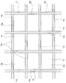
- the perspective view showing the appearance of the sunlight type plant factory in one embodiment of this application The top view of a part of roof of the solar-powered plant factory shown in FIG.
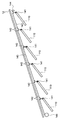
- the side view which shows notionally the mounting structure of the photovoltaic power generation panel in the solar-powered plant factory shown in FIG. The top view which shows notionally the mounting structure of the solar power generation panel in the solar-powered plant factory shown in FIG.
- the solar-powered plant factory (hereinafter, simply referred to as “plant factory”) in this embodiment has a building 1.
- the building 1 has an indoor space inside, and has a function of isolating the indoor space from the external environment.
- the building 1 itself may be the same as the structure of the conventional solar-powered plant factory, and is not limited to this, but in this embodiment, it is.
- the plants to be cultivated in the plant factory are cultivated.
- the method of cultivating the plant performed in the building 1 may be the same as the conventional one, but is not limited to this, but in this embodiment, the conventional method of cultivating the plant is followed.
- the method of cultivating the plant may be hydroponic culture, soil culture, or other solid medium culture.
- the building 1 includes a wall 11 and a roof 12.
- the wall 11 and the roof 12 are supported by columns and beams (not shown). Sunlight transmitted through the wall 11 or the roof 12 is incident on the indoor space inside the building 1.
- the wall 11 may also be transparent, but at least a part of the roof 12 is transparent so that sunlight can be guided into the interior space of the building 1 through the roof 12.
- the wall 11 is provided with an openable/closable door 11a for entering and leaving the indoor space of the building 1.
- the roof 12 is a gable type in this embodiment, the shape of the roof 12 is not limited to this, and for example, a well-known or well-known shape such as a hipped roof, a saw roof, a flat roof, and a one-sided roof is adopted. be able to.
- the roof 12 in this embodiment is configured as shown in the enlarged view of FIG.
- the roof 12 includes a frame material 13.
- the frame member 13 is made of metal.
- the frame member 13 is a rod-shaped member that is a plurality of rod-shaped members arranged in parallel with each other in a direction along the maximum inclination direction of the roof 12, and a horizontal direction that is orthogonal to the inclined rod-shaped member 13a.
- a horizontal rod-shaped member 13b which is a rod-shaped member arranged in parallel with each other.
- the intervals between the adjacent slant rod-shaped members 13 a are all the same in all parts of the roof 12.
- the intervals between the adjacent horizontal rod-shaped members 13b are all the same in all parts of the roof 12.
- the frame member 13 has a large number of rectangular windows 13c arranged vertically and horizontally in a grid pattern and surrounded by two adjacent inclined bar members 13a and two adjacent horizontal bar members 13b. Will be formed.
- the size and shape of each window 13c are not limited to this, but are the same in this embodiment.
- a window member 14 is fitted in each window portion 13c.
- the window member 14 is made of a translucent plate or film.
- the window member 14 may be publicly known or well known. In the case of a plate, the window member 14 can be made of, for example, glass, acrylic, or another resin.
- the window member 14 can be formed of, for example, vinyl chloride resin, polyethylene resin, or the like.
- the translucency that the window member 14 should have is, for example, 75% or more.
- the window member 14 in this embodiment has a size and a shape corresponding to each of the window portions 13c, and is fitted in each window portion 13c, and the window portion 13c is opened by, for example, a known method or a known appropriate method. It is fixed to the slanted rod-shaped member 13a and the horizontal rod-shaped member 13b that define it.
- the window member 14 does not need to be divided in units of the window portions 13c, and one window member 14 that is sized and shaped so as to straddle a plurality of adjacent window portions 13c may be a plurality of adjacent window portions 13c.
- the window portion 13c may be covered.
- a plurality of photovoltaic power generation panels 110 are provided in the indoor space of the building 1.
- the solar power generation panel 110 is provided with a light receiving surface 111 on its upper surface, and receives light from the light receiving surface 111 to generate power. Since the photovoltaic panel 110 is used in the indoor space of the building 1, it does not require high weather resistance.
- the photovoltaic panel 110 that does not have high weather resistance can have a simple configuration such as a PV cell (photovoltaic cell) attached to an acrylic plate or other plastic plate. The surface of the plastic plate to which the PV cell is attached becomes the light receiving surface 111.
- Such a solar power generation panel 110 can be manufactured at low cost and is lighter than a general solar power generation panel.
- all photovoltaic panels 110 are rectangular and plate-shaped. Of course, the four corners may be chamfered, or the plate may be a corrugated plate instead of a flat plate.
- all of the photovoltaic power generation panels 110 in this embodiment have light-receiving surfaces 111 having the same size and shape.
- all the photovoltaic power generation panels 110 in this embodiment have the same configuration.
- the size and shape of the light receiving surface 111 of each photovoltaic power generation panel 110 substantially correspond to the size and shape of the window portion 13c in the roof 12, and are configured to be slightly smaller than that.
- the plurality of photovoltaic panels 110 are arranged vertically and horizontally corresponding to the window members 14 on the roof 12, respectively. Each solar power generation panel 110 is arranged immediately below the window 13c. However, it is not required that the center of the light receiving surface 111 of the photovoltaic power generation panel 110 be directly below the center of the window 13c. Each of the photovoltaic power generation panels 110 is arranged under each of the window portions 13c because the shadow of the frame material 13 around the window portions 13c falls on the light receiving surface 111 of the photovoltaic power generation panel 110. This is to prevent the power generation efficiency from decreasing. The sun moves from east to west during the day, and its altitude varies depending on the season.
- the photovoltaic power generation panels 110 are arranged at positions where the reduction in the power generation efficiency of the photovoltaic power generation panel 110 due to the shadow formed by the frame material 13 can be most suppressed. At least the photovoltaic power generation panel 110 should be positioned as close to the lower surface of the roof 12 as possible within a range in which a change in angle as will be described later is allowed. It is advantageous to prevent shadows from falling.
- the photovoltaic power generation panel 100 in this embodiment can change their inclination in the north-south direction.
- the altitude of the sun changes depending on the season.
- the orientation of the light receiving surface 111 of the solar power generation panel 110 can be made to follow the seasonal elevation change of the sun, and the sunlight hitting the light receiving surface 111 can be changed. It is possible to keep the angle as close to vertical as possible. Thereby, the power generation efficiency in the photovoltaic power generation panel 110 can be improved.
- the angle change of the solar power generation panel in the north-south direction may be continuous or may be batch-type such as every 24 hours or once a week.
- At least a plurality of the multiple photovoltaic panels 110 in this embodiment are configured such that their inclinations are collectively changed by driving one power unit. ing. More specifically, among the photovoltaic panels 110 in this embodiment, one row of photovoltaic panels in the direction of inclination of the roof 12 has its inclination changed collectively by driving one power unit. It is supposed to be done. However, the range of the photovoltaic panels 110 whose tilts are collectively changed by one power unit does not have to be one row of photovoltaic panels 110 in the tilt direction of the roof 12.
- one row of solar power generation panels 110 arranged in the horizontal direction may be configured so that their inclinations can be collectively changed by one power unit, and 9 solar power generations of 3 ⁇ 3.
- the tilts of the panels 110 may be collectively changed by one power unit, and all the solar panels 110 may be collectively tilted by one power unit. It doesn't matter if it is like this.
- FIGS. 3 An example of a mechanism for changing the angle of the photovoltaic panel 110 is schematically shown in FIGS. 3 is a side view and FIG. 4 is a plan view.
- the photovoltaic panel 110 is directly below the roof 12.
- FIG. 3 in this example, six solar power generation panels 110 are arranged in the inclination direction of the roof 12.
- the inclination angle of a set of six photovoltaic panels 110 arranged in the inclination direction of the roof 12 is collectively changed by one drive device described later.
- the mechanism shown in FIGS. 3 and 4 can also be adopted in other solar power generation panels 110 arranged in the inclination direction of the roof 12, and this is not always the case, but this is the case in this embodiment.
- Each of the photovoltaic power generation panels 110 faces south, and the light receiving surface 111 thereof faces upward. Although not limited to this, the upper and lower sides of each rectangular photovoltaic power generation panel 110 are horizontal.
- Each solar power generation panel 110 has an upper rod body 131, which is a rod-shaped body extending along the slope of the roof 12 on both outer sides of the upper side of the solar power generation panel 110, on each side surface immediately below the upper side thereof. Is supported. More specifically, the upper rod 131 and the solar power generation panel 110 are connected by a cylindrical upper shaft 132 that is rotatable with respect to each of the upper rod 131 and the solar power generation panel 110. ing.
- the upper shaft 132 serves as an axis, and the angle between the upper rod 131 and the photovoltaic power generation panel 110 when viewed from the side is changeable.
- Each solar power generation panel 110 is a lower rod body that is a rod-shaped body that extends along the slope of the roof 12 on both sides of the lower side of the solar power generation panel 110 on both outer sides of the lower side of the solar power generation panel 110. It is supported by 133. More specifically, the lower rod body 133 and the photovoltaic power generation panel 110 are connected by a lower shaft 134 having a cylindrical shape that is rotatable with respect to each of the lower rod body 133 and the photovoltaic power generation panel 110. ing.
- the lower shaft 134 serves as an axis, and the angle between the lower rod 133 and the photovoltaic panel 110 when viewed from the side is changeable.
- the upper rod body 131 and the lower rod body 133 are connected to the drive device 135.
- the drive device 135 can move at least one of the upper rod body 131 and the lower rod body 133 in the length direction thereof in accordance with an appropriate driving force such as hydraulic pressure.
- the position of the lower rod body 133 is moved to the right in FIGS.
- the distance between the lower rod body 133 and the upper rod body 131 is expanded, and the lower rod body 133 is supported by the upper rod body 131 and the lower rod body 133.
- the photovoltaic panels 110 all stand up by the same angle.
- the position of the lower rod body 133 is moved to the left in FIGS. 3 and 4, for example, the distance between the lower rod body 133 and the upper rod body 131 is narrowed, and the upper rod body 131 and the lower rod body 133 are separated.
- the supported photovoltaic panels 110 all sleep at the same angle. In this way, the tilt angles of a plurality of, in this example, six photovoltaic panels 110 can be collectively changed in the same manner by driving only one drive device 135.
- the drive device 135 does not need to be fixed to the drive device 135 and may be directly or indirectly through another member. It can be fixed to the building 1. Further, the driving device 135 does not have to be arranged inside the building 1, and may be provided outside the building 1.
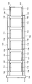
- the change of the angle of the photovoltaic power generation panel 110 can be achieved not only by the mechanism shown in FIGS. 3 and 4 but also by the mechanism shown in the side view of FIG.
- the side view of FIG. 5 is for changing the height in the vicinity of the corresponding apex (for example, the apex at the upper right of each solar panel 110 shown in FIG. 2) of the solar panel 110. It is a conceptual representation of the mechanism.
- An upper right pulley 141 which is a pulley, is provided near the upper right of FIG. 3 of each photovoltaic panel 110.
- two upper right pulleys 142 which are two pulleys, are provided.
- a wire or other linear member 143 is wound around the upper right pulley 141 and the upper right auxiliary pulley 142.
- the distal end of the linear body 143 is fixed to a fixed body 144 which is a predetermined object for fixing the distal end of the linear body 143, and the proximal end of the linear body 143 is wound around a drum 145.
- the drum 145 is rotatable by a driving device (not shown), and is capable of winding or unwinding the filament body 143. When the drum 145 winds the filament body 143, the length of the filament body 143 from the drum 145 to the fixed body 144 becomes shorter, and the position of each upper right auxiliary pulley 142 remains unchanged.
- the upper right pulley is pulled up, and the upper right portion of the photovoltaic panel 110 is pulled up.
- the drum 145 unwinds the filament body 143
- the length of the filament body 143 from the drum 145 to the fixed body 144 becomes long, and the position of each upper right auxiliary pulley 142 remains unchanged.
- the upper right pulley of the panel 110 is lowered, and the upper right portion of the photovoltaic power generation panel 110 is lowered.
- the upper right portion of the photovoltaic power generation panel 110 can be collectively changed in the vertical position by driving the driving device (not shown).
- all the upper right portions of the photovoltaic panels 110 under the roof 12 are collectively driven by one drive device. It can also be moved up and down.
- the configuration shown in FIG. 5 is, for example, not only in the upper right corner of the photovoltaic power generation panel 110 shown in FIG. Alternatively, it can be adopted at four locations near the four vertices of the photovoltaic panel 110. As a result, the upper and lower positions of the solar power generation panel 110, or the four corners of the solar power generation panel 110 can be collectively changed in the vertical direction by driving a driving device (not shown). become able to.
- the former the two vertices that do not move up and down may be simply hung by a linear body
- it is possible to change the inclinations of the plurality of photovoltaic panels 110 in the north-south direction. If the latter is adopted, it becomes possible to freely change the inclination in the north-south direction and the inclination in the east-west direction of the plurality of photovoltaic power generation panels 110.
- the latter it is also possible to change the direction of the light receiving surface of the photovoltaic power generation panel in accordance with the movement of the sun during the day.
- the method of using the plant factory as described above is the same as the method of using the conventional plant factory.
- the photovoltaic power generation panel 110 generates power.
- a solar-powered plant factory for example, electric power is required for nighttime lighting, air conditioning for indoor air conditioning, humidity adjustment, and the like.
- the power generated by the photovoltaic power generation panel 110 generating power can be used as power required for lighting, air conditioning, and the like.
- the electric power generated by the solar power generation panel 110 may be a target for power sale. This makes it possible to indirectly reduce the running cost of the plant factory. Further, by arranging the photovoltaic power generation panel 110 under the roof 12 of the building 1, the following secondary effects are also produced.
- the photovoltaic panel 110 below the roof 12 and above the plant to be cultivated allows the plant to be placed in the shadow produced by the photovoltaic panel 110.
- the interior of the building 1 can be cooled compared to when the photovoltaic panel 110 is not present.
- the solar power generation panel 110 is provided inside the building 1, particularly immediately below the roof 12, so that such a device does not need to be devised.
- the solar panels 110 are connected in parallel.
- the large number of photovoltaic power generation panels 110 are arranged in series.
- a large number of solar panels 110 are connected in series and dirt is attached to the light receiving surface 111 of one of the solar panels 110 due to dead leaves or twigs (most sunlight In the case of the present invention in which the power generation panel 110 is in the indoor space of the building 1, such a situation is difficult to imagine), or dead leaves and twigs are placed on the window member 14 on the solar power generation panel 110 to stain the window member 14.
- the power generation capacity of the solar power generation panel 110 becomes lower than the power generation capacity of other solar power generation panels 110.
- the photovoltaic power generation panel 110 When such a decrease in power generation occurs in one of the photovoltaic power generation panels 110 in a power generation facility in which a large number of photovoltaic power generation panels 110 are connected in series, the photovoltaic power generation panel 110 is connected to the other photovoltaic power generation panels 110 in series.
- the solar power generation panel 110 of the present invention functions as a resistance, so to speak, and tends to greatly affect the power generation capacity of the entire power generation facility.
- the photovoltaic panel 110 is It does not function as a resistance to the photovoltaic power generation panel 110, and its effect is that the amount of current output from the power generation equipment including a large number of photovoltaic power generation panels 110 is from the photovoltaic power generation panel 110 in which the amount of current has decreased. Since it is only reduced by the amount of decrease in the amount of current, the above-mentioned great influence does not occur.
- the photovoltaic panel 110 can be hung using the filament 143.
- each photovoltaic power generation panel 110 can be tilted arbitrarily in the north-south direction or the east-west direction.
- the plurality of solar power generation panels 110 can change their inclinations in the east-west direction, the plurality of solar power generation panels 110 are In the morning and evening hours, by setting the light receiving surface 111 of the photovoltaic power generation panel 110 in either the east or west direction to be vertical or substantially vertical, the light receiving surface 111 of the photovoltaic power generation panel 110 may face the sun.
- the light-receiving surface 111 of the photovoltaic power generation panel 110 does not need to face exactly east or west exactly, and the light-receiving surface 111 is within 30 degrees (preferably within 15 degrees) in the horizontal direction from the direction of the sun. ) It is sufficient if it faces in the direction of.
- the angle formed by the straight line along the maximum inclination direction of the light receiving surface 111 of the photovoltaic power generation panel 110 and the vertical straight line is within 15 degrees (preferably within 10 degrees). That's enough.
- “Morning and evening” means a time zone of up to 15 degrees if the sun altitude (elevation angle) has a margin (up to 10 degrees if there is no margin). Such a configuration is useful for maintaining the power generation efficiency of each photovoltaic panel 110 even in the morning and evening hours. If such a configuration is adopted, the photovoltaic power generation panels 110 may be located at overlapping positions when viewed from the sun, but in order to maintain the power generation efficiency of the photovoltaic power generation panel 110 on the rear side to some extent. It is preferable that each solar power generation panel 110 be of a type that transmits sunlight.
Landscapes
- Life Sciences & Earth Sciences (AREA)
- Environmental Sciences (AREA)
- Sustainable Development (AREA)
- Photovoltaic Devices (AREA)
- Greenhouses (AREA)
- Roof Covering Using Slabs Or Stiff Sheets (AREA)
Abstract
La présente invention concerne une technologie pour limiter les coûts d'une usine de production de plantes ayant des panneaux photovoltaïques. Une usine de production de plantes du type à lumière solaire comprend un bâtiment. Le toit 12 du bâtiment est transparent, et la lumière solaire peut entrer dans l'espace intérieur du bâtiment. Des panneaux photovoltaïques 10 sont disposés dans l'espace intérieur du bâtiment. L'angle d'inclinaison des panneaux photovoltaïques 110 peut être changé dans la direction nord-sud.
Applications Claiming Priority (2)
| Application Number | Priority Date | Filing Date | Title |
|---|---|---|---|
| JP2019-029562 | 2019-02-21 | ||
| JP2019029562A JP2020130075A (ja) | 2019-02-21 | 2019-02-21 | 植物工場 |
Publications (1)
| Publication Number | Publication Date |
|---|---|
| WO2020171231A1 true WO2020171231A1 (fr) | 2020-08-27 |
Family
ID=72144716
Family Applications (1)
| Application Number | Title | Priority Date | Filing Date |
|---|---|---|---|
| PCT/JP2020/007246 Ceased WO2020171231A1 (fr) | 2019-02-21 | 2020-02-21 | Usine de production de plantes |
Country Status (2)
| Country | Link |
|---|---|
| JP (1) | JP2020130075A (fr) |
| WO (1) | WO2020171231A1 (fr) |
Cited By (1)
| Publication number | Priority date | Publication date | Assignee | Title |
|---|---|---|---|---|
| CN116743043B (zh) * | 2023-05-23 | 2023-12-15 | 广东旭科太阳能科技有限公司 | 光伏阳光房 |
Families Citing this family (2)
| Publication number | Priority date | Publication date | Assignee | Title |
|---|---|---|---|---|
| JP2023141645A (ja) * | 2022-03-24 | 2023-10-05 | 積水化学工業株式会社 | シート構造物及びシート構造物における発電部の取付構造 |
| JP7584774B1 (ja) | 2023-12-18 | 2024-11-18 | ノータス研究所株式会社 | 植物栽培システム |
Citations (2)
| Publication number | Priority date | Publication date | Assignee | Title |
|---|---|---|---|---|
| JP3164866U (ja) * | 2010-09-07 | 2010-12-24 | 東南電気工事株式会社 | ソーラパネル装置 |
| JP3199175U (ja) * | 2015-05-29 | 2015-08-06 | 三朗 宇梶 | ソーラーパネルを備えた栽培ハウス |
-
2019
- 2019-02-21 JP JP2019029562A patent/JP2020130075A/ja active Pending
-
2020
- 2020-02-21 WO PCT/JP2020/007246 patent/WO2020171231A1/fr not_active Ceased
Patent Citations (2)
| Publication number | Priority date | Publication date | Assignee | Title |
|---|---|---|---|---|
| JP3164866U (ja) * | 2010-09-07 | 2010-12-24 | 東南電気工事株式会社 | ソーラパネル装置 |
| JP3199175U (ja) * | 2015-05-29 | 2015-08-06 | 三朗 宇梶 | ソーラーパネルを備えた栽培ハウス |
Cited By (1)
| Publication number | Priority date | Publication date | Assignee | Title |
|---|---|---|---|---|
| CN116743043B (zh) * | 2023-05-23 | 2023-12-15 | 广东旭科太阳能科技有限公司 | 光伏阳光房 |
Also Published As
| Publication number | Publication date |
|---|---|
| JP2020130075A (ja) | 2020-08-31 |
Similar Documents
| Publication | Publication Date | Title |
|---|---|---|
| JP2020534805A (ja) | 農業施設に設置可能な太陽光発電プラント | |
| US8418401B2 (en) | Photovoltaic greenhouse structure | |
| US10738473B2 (en) | Solar shading module, glazed structure, building, and method of operating a solar shading module | |
| CN105028030B (zh) | 一种可调透光率的光伏发电温室 | |
| KR100980688B1 (ko) | 발전과 차양을 겸하는 건축물 일체형 태양광 발전장치 | |
| US11812710B2 (en) | Arrangement of photovoltaic panels and system for optimizing angular positioning of photovoltaic panels in a greenhouse | |
| CN114222496B (zh) | 具有光伏系统的温室 | |
| WO2020171231A1 (fr) | Usine de production de plantes | |
| KR20130022230A (ko) | 태양전지를 구비한 농업용 하우스 | |
| KR101336154B1 (ko) | 차광막 내장 이중창을 구비하는 온실 | |
| KR20190013187A (ko) | 태양광 반사판을 이용한 태양광 발전 온실 | |
| US20230413741A1 (en) | Arrangement of photovoltaic panels and system for optimizing angular positioning of photovoltaic panels in a greenhouse | |
| KR200458057Y1 (ko) | 태양광 집광 및 제어를 위한 차양을 포함하는 천창 및 창호 시스템 | |
| JP7137972B2 (ja) | 施設栽培用の施設 | |
| JP6842743B2 (ja) | ソーラーシェアリングシステム | |
| JP3199175U (ja) | ソーラーパネルを備えた栽培ハウス | |
| KR102317367B1 (ko) | 농경지용 태양광 발전장치 | |
| WO2014180098A1 (fr) | Procédé d'application de composant de génération de puissance photovoltaïque tubulaire | |
| JP2010193837A (ja) | 複数の太陽電池モジュールを配設した温室及び太陽電池モジュールの配設方法 | |
| KR20150142815A (ko) | 태양에너지 발전 지붕 | |
| JP6933596B2 (ja) | 太陽光発電システム | |
| IL281407B1 (en) | Arrangement of photovoltaic panels and system for optimizing angular positioning of photovoltaic panels in a greenhouse | |
| Vorndran et al. | Hybrid photovoltaic/daylighting module for greenhouse environmental control | |
| BG4320U1 (bg) | Самопочистваща конструкция за двулицеви фотоволтаични панели - подреждане изток запад | |
| Sonneveld et al. | Static linear Fresnel lenses as LCPV system in a greenhouse |
Legal Events
| Date | Code | Title | Description |
|---|---|---|---|
| 121 | Ep: the epo has been informed by wipo that ep was designated in this application |
Ref document number: 20758593 Country of ref document: EP Kind code of ref document: A1 |
|
| NENP | Non-entry into the national phase |
Ref country code: DE |
|
| 122 | Ep: pct application non-entry in european phase |
Ref document number: 20758593 Country of ref document: EP Kind code of ref document: A1 |