WO2020171239A1 - Appareil d'électrolyse de l'eau, procédé de stérilisation/nettoyage et procédé de décomposition/d'élimination de substance nocive, faisant chacun intervenir un appareil d'électrolyse de l'eau - Google Patents
Appareil d'électrolyse de l'eau, procédé de stérilisation/nettoyage et procédé de décomposition/d'élimination de substance nocive, faisant chacun intervenir un appareil d'électrolyse de l'eau Download PDFInfo
- Publication number
- WO2020171239A1 WO2020171239A1 PCT/JP2020/007521 JP2020007521W WO2020171239A1 WO 2020171239 A1 WO2020171239 A1 WO 2020171239A1 JP 2020007521 W JP2020007521 W JP 2020007521W WO 2020171239 A1 WO2020171239 A1 WO 2020171239A1
- Authority
- WO
- WIPO (PCT)
- Prior art keywords
- water
- electrode
- anode
- cathode
- water electrolysis
- Prior art date
- Legal status (The legal status is an assumption and is not a legal conclusion. Google has not performed a legal analysis and makes no representation as to the accuracy of the status listed.)
- Ceased
Links
Images
























Classifications
-
- C—CHEMISTRY; METALLURGY
- C25—ELECTROLYTIC OR ELECTROPHORETIC PROCESSES; APPARATUS THEREFOR
- C25B—ELECTROLYTIC OR ELECTROPHORETIC PROCESSES FOR THE PRODUCTION OF COMPOUNDS OR NON-METALS; APPARATUS THEREFOR
- C25B1/00—Electrolytic production of inorganic compounds or non-metals
- C25B1/01—Products
- C25B1/28—Per-compounds
- C25B1/30—Peroxides
-
- C—CHEMISTRY; METALLURGY
- C25—ELECTROLYTIC OR ELECTROPHORETIC PROCESSES; APPARATUS THEREFOR
- C25B—ELECTROLYTIC OR ELECTROPHORETIC PROCESSES FOR THE PRODUCTION OF COMPOUNDS OR NON-METALS; APPARATUS THEREFOR
- C25B15/00—Operating or servicing cells
- C25B15/08—Supplying or removing reactants or electrolytes; Regeneration of electrolytes
-
- C—CHEMISTRY; METALLURGY
- C02—TREATMENT OF WATER, WASTE WATER, SEWAGE, OR SLUDGE
- C02F—TREATMENT OF WATER, WASTE WATER, SEWAGE, OR SLUDGE
- C02F1/00—Treatment of water, waste water, or sewage
- C02F1/46—Treatment of water, waste water, or sewage by electrochemical methods
- C02F1/461—Treatment of water, waste water, or sewage by electrochemical methods by electrolysis
- C02F1/46104—Devices therefor; Their operating or servicing
-
- C—CHEMISTRY; METALLURGY
- C25—ELECTROLYTIC OR ELECTROPHORETIC PROCESSES; APPARATUS THEREFOR
- C25B—ELECTROLYTIC OR ELECTROPHORETIC PROCESSES FOR THE PRODUCTION OF COMPOUNDS OR NON-METALS; APPARATUS THEREFOR
- C25B1/00—Electrolytic production of inorganic compounds or non-metals
- C25B1/01—Products
- C25B1/13—Ozone
-
- C—CHEMISTRY; METALLURGY
- C25—ELECTROLYTIC OR ELECTROPHORETIC PROCESSES; APPARATUS THEREFOR
- C25B—ELECTROLYTIC OR ELECTROPHORETIC PROCESSES FOR THE PRODUCTION OF COMPOUNDS OR NON-METALS; APPARATUS THEREFOR
- C25B11/00—Electrodes; Manufacture thereof not otherwise provided for
-
- C—CHEMISTRY; METALLURGY
- C25—ELECTROLYTIC OR ELECTROPHORETIC PROCESSES; APPARATUS THEREFOR
- C25B—ELECTROLYTIC OR ELECTROPHORETIC PROCESSES FOR THE PRODUCTION OF COMPOUNDS OR NON-METALS; APPARATUS THEREFOR
- C25B11/00—Electrodes; Manufacture thereof not otherwise provided for
- C25B11/02—Electrodes; Manufacture thereof not otherwise provided for characterised by shape or form
-
- C—CHEMISTRY; METALLURGY
- C25—ELECTROLYTIC OR ELECTROPHORETIC PROCESSES; APPARATUS THEREFOR
- C25B—ELECTROLYTIC OR ELECTROPHORETIC PROCESSES FOR THE PRODUCTION OF COMPOUNDS OR NON-METALS; APPARATUS THEREFOR
- C25B11/00—Electrodes; Manufacture thereof not otherwise provided for
- C25B11/02—Electrodes; Manufacture thereof not otherwise provided for characterised by shape or form
- C25B11/03—Electrodes; Manufacture thereof not otherwise provided for characterised by shape or form perforated or foraminous
-
- C—CHEMISTRY; METALLURGY
- C25—ELECTROLYTIC OR ELECTROPHORETIC PROCESSES; APPARATUS THEREFOR
- C25B—ELECTROLYTIC OR ELECTROPHORETIC PROCESSES FOR THE PRODUCTION OF COMPOUNDS OR NON-METALS; APPARATUS THEREFOR
- C25B11/00—Electrodes; Manufacture thereof not otherwise provided for
- C25B11/02—Electrodes; Manufacture thereof not otherwise provided for characterised by shape or form
- C25B11/03—Electrodes; Manufacture thereof not otherwise provided for characterised by shape or form perforated or foraminous
- C25B11/031—Porous electrodes
-
- C—CHEMISTRY; METALLURGY
- C25—ELECTROLYTIC OR ELECTROPHORETIC PROCESSES; APPARATUS THEREFOR
- C25B—ELECTROLYTIC OR ELECTROPHORETIC PROCESSES FOR THE PRODUCTION OF COMPOUNDS OR NON-METALS; APPARATUS THEREFOR
- C25B11/00—Electrodes; Manufacture thereof not otherwise provided for
- C25B11/02—Electrodes; Manufacture thereof not otherwise provided for characterised by shape or form
- C25B11/036—Bipolar electrodes
-
- C—CHEMISTRY; METALLURGY
- C25—ELECTROLYTIC OR ELECTROPHORETIC PROCESSES; APPARATUS THEREFOR
- C25B—ELECTROLYTIC OR ELECTROPHORETIC PROCESSES FOR THE PRODUCTION OF COMPOUNDS OR NON-METALS; APPARATUS THEREFOR
- C25B11/00—Electrodes; Manufacture thereof not otherwise provided for
- C25B11/04—Electrodes; Manufacture thereof not otherwise provided for characterised by the material
- C25B11/042—Electrodes formed of a single material
- C25B11/043—Carbon, e.g. diamond or graphene
- C25B11/044—Impregnation of carbon
-
- C—CHEMISTRY; METALLURGY
- C25—ELECTROLYTIC OR ELECTROPHORETIC PROCESSES; APPARATUS THEREFOR
- C25B—ELECTROLYTIC OR ELECTROPHORETIC PROCESSES FOR THE PRODUCTION OF COMPOUNDS OR NON-METALS; APPARATUS THEREFOR
- C25B13/00—Diaphragms; Spacing elements
- C25B13/02—Diaphragms; Spacing elements characterised by shape or form
-
- C—CHEMISTRY; METALLURGY
- C25—ELECTROLYTIC OR ELECTROPHORETIC PROCESSES; APPARATUS THEREFOR
- C25B—ELECTROLYTIC OR ELECTROPHORETIC PROCESSES FOR THE PRODUCTION OF COMPOUNDS OR NON-METALS; APPARATUS THEREFOR
- C25B13/00—Diaphragms; Spacing elements
- C25B13/04—Diaphragms; Spacing elements characterised by the material
- C25B13/08—Diaphragms; Spacing elements characterised by the material based on organic materials
-
- C—CHEMISTRY; METALLURGY
- C25—ELECTROLYTIC OR ELECTROPHORETIC PROCESSES; APPARATUS THEREFOR
- C25B—ELECTROLYTIC OR ELECTROPHORETIC PROCESSES FOR THE PRODUCTION OF COMPOUNDS OR NON-METALS; APPARATUS THEREFOR
- C25B9/00—Cells or assemblies of cells; Constructional parts of cells; Assemblies of constructional parts, e.g. electrode-diaphragm assemblies; Process-related cell features
- C25B9/13—Single electrolytic cells with circulation of an electrolyte
- C25B9/15—Flow-through cells
-
- C—CHEMISTRY; METALLURGY
- C25—ELECTROLYTIC OR ELECTROPHORETIC PROCESSES; APPARATUS THEREFOR
- C25B—ELECTROLYTIC OR ELECTROPHORETIC PROCESSES FOR THE PRODUCTION OF COMPOUNDS OR NON-METALS; APPARATUS THEREFOR
- C25B9/00—Cells or assemblies of cells; Constructional parts of cells; Assemblies of constructional parts, e.g. electrode-diaphragm assemblies; Process-related cell features
- C25B9/17—Cells comprising dimensionally-stable non-movable electrodes; Assemblies of constructional parts thereof
- C25B9/19—Cells comprising dimensionally-stable non-movable electrodes; Assemblies of constructional parts thereof with diaphragms
-
- C—CHEMISTRY; METALLURGY
- C25—ELECTROLYTIC OR ELECTROPHORETIC PROCESSES; APPARATUS THEREFOR
- C25B—ELECTROLYTIC OR ELECTROPHORETIC PROCESSES FOR THE PRODUCTION OF COMPOUNDS OR NON-METALS; APPARATUS THEREFOR
- C25B9/00—Cells or assemblies of cells; Constructional parts of cells; Assemblies of constructional parts, e.g. electrode-diaphragm assemblies; Process-related cell features
- C25B9/60—Constructional parts of cells
-
- C—CHEMISTRY; METALLURGY
- C25—ELECTROLYTIC OR ELECTROPHORETIC PROCESSES; APPARATUS THEREFOR
- C25B—ELECTROLYTIC OR ELECTROPHORETIC PROCESSES FOR THE PRODUCTION OF COMPOUNDS OR NON-METALS; APPARATUS THEREFOR
- C25B9/00—Cells or assemblies of cells; Constructional parts of cells; Assemblies of constructional parts, e.g. electrode-diaphragm assemblies; Process-related cell features
- C25B9/70—Assemblies comprising two or more cells
- C25B9/73—Assemblies comprising two or more cells of the filter-press type
- C25B9/77—Assemblies comprising two or more cells of the filter-press type having diaphragms
-
- C—CHEMISTRY; METALLURGY
- C02—TREATMENT OF WATER, WASTE WATER, SEWAGE, OR SLUDGE
- C02F—TREATMENT OF WATER, WASTE WATER, SEWAGE, OR SLUDGE
- C02F1/00—Treatment of water, waste water, or sewage
- C02F1/72—Treatment of water, waste water, or sewage by oxidation
- C02F1/722—Oxidation by peroxides
-
- C—CHEMISTRY; METALLURGY
- C02—TREATMENT OF WATER, WASTE WATER, SEWAGE, OR SLUDGE
- C02F—TREATMENT OF WATER, WASTE WATER, SEWAGE, OR SLUDGE
- C02F1/00—Treatment of water, waste water, or sewage
- C02F1/72—Treatment of water, waste water, or sewage by oxidation
- C02F1/78—Treatment of water, waste water, or sewage by oxidation with ozone
-
- C—CHEMISTRY; METALLURGY
- C02—TREATMENT OF WATER, WASTE WATER, SEWAGE, OR SLUDGE
- C02F—TREATMENT OF WATER, WASTE WATER, SEWAGE, OR SLUDGE
- C02F1/00—Treatment of water, waste water, or sewage
- C02F1/46—Treatment of water, waste water, or sewage by electrochemical methods
- C02F1/461—Treatment of water, waste water, or sewage by electrochemical methods by electrolysis
- C02F1/46104—Devices therefor; Their operating or servicing
- C02F1/46109—Electrodes
- C02F2001/46133—Electrodes characterised by the material
-
- C—CHEMISTRY; METALLURGY
- C02—TREATMENT OF WATER, WASTE WATER, SEWAGE, OR SLUDGE
- C02F—TREATMENT OF WATER, WASTE WATER, SEWAGE, OR SLUDGE
- C02F2101/00—Nature of the contaminant
- C02F2101/10—Inorganic compounds
- C02F2101/16—Nitrogen compounds, e.g. ammonia
-
- C—CHEMISTRY; METALLURGY
- C02—TREATMENT OF WATER, WASTE WATER, SEWAGE, OR SLUDGE
- C02F—TREATMENT OF WATER, WASTE WATER, SEWAGE, OR SLUDGE
- C02F2101/00—Nature of the contaminant
- C02F2101/10—Inorganic compounds
- C02F2101/16—Nitrogen compounds, e.g. ammonia
- C02F2101/18—Cyanides
-
- C—CHEMISTRY; METALLURGY
- C02—TREATMENT OF WATER, WASTE WATER, SEWAGE, OR SLUDGE
- C02F—TREATMENT OF WATER, WASTE WATER, SEWAGE, OR SLUDGE
- C02F2201/00—Apparatus for treatment of water, waste water or sewage
- C02F2201/46—Apparatus for electrochemical processes
- C02F2201/461—Electrolysis apparatus
- C02F2201/46105—Details relating to the electrolytic devices
- C02F2201/46115—Electrolytic cell with membranes or diaphragms
-
- C—CHEMISTRY; METALLURGY
- C02—TREATMENT OF WATER, WASTE WATER, SEWAGE, OR SLUDGE
- C02F—TREATMENT OF WATER, WASTE WATER, SEWAGE, OR SLUDGE
- C02F2201/00—Apparatus for treatment of water, waste water or sewage
- C02F2201/46—Apparatus for electrochemical processes
- C02F2201/461—Electrolysis apparatus
- C02F2201/46105—Details relating to the electrolytic devices
- C02F2201/4612—Controlling or monitoring
- C02F2201/46125—Electrical variables
- C02F2201/46135—Voltage
-
- C—CHEMISTRY; METALLURGY
- C02—TREATMENT OF WATER, WASTE WATER, SEWAGE, OR SLUDGE
- C02F—TREATMENT OF WATER, WASTE WATER, SEWAGE, OR SLUDGE
- C02F2201/00—Apparatus for treatment of water, waste water or sewage
- C02F2201/46—Apparatus for electrochemical processes
- C02F2201/461—Electrolysis apparatus
- C02F2201/46105—Details relating to the electrolytic devices
- C02F2201/4612—Controlling or monitoring
- C02F2201/46145—Fluid flow
-
- C—CHEMISTRY; METALLURGY
- C02—TREATMENT OF WATER, WASTE WATER, SEWAGE, OR SLUDGE
- C02F—TREATMENT OF WATER, WASTE WATER, SEWAGE, OR SLUDGE
- C02F2303/00—Specific treatment goals
- C02F2303/04—Disinfection
-
- C—CHEMISTRY; METALLURGY
- C02—TREATMENT OF WATER, WASTE WATER, SEWAGE, OR SLUDGE
- C02F—TREATMENT OF WATER, WASTE WATER, SEWAGE, OR SLUDGE
- C02F2303/00—Specific treatment goals
- C02F2303/22—Eliminating or preventing deposits, scale removal, scale prevention
-
- C—CHEMISTRY; METALLURGY
- C02—TREATMENT OF WATER, WASTE WATER, SEWAGE, OR SLUDGE
- C02F—TREATMENT OF WATER, WASTE WATER, SEWAGE, OR SLUDGE
- C02F2305/00—Use of specific compounds during water treatment
- C02F2305/02—Specific form of oxidant
- C02F2305/023—Reactive oxygen species, singlet oxygen, OH radical
-
- C—CHEMISTRY; METALLURGY
- C25—ELECTROLYTIC OR ELECTROPHORETIC PROCESSES; APPARATUS THEREFOR
- C25B—ELECTROLYTIC OR ELECTROPHORETIC PROCESSES FOR THE PRODUCTION OF COMPOUNDS OR NON-METALS; APPARATUS THEREFOR
- C25B1/00—Electrolytic production of inorganic compounds or non-metals
- C25B1/01—Products
- C25B1/02—Hydrogen or oxygen
- C25B1/04—Hydrogen or oxygen by electrolysis of water
-
- Y—GENERAL TAGGING OF NEW TECHNOLOGICAL DEVELOPMENTS; GENERAL TAGGING OF CROSS-SECTIONAL TECHNOLOGIES SPANNING OVER SEVERAL SECTIONS OF THE IPC; TECHNICAL SUBJECTS COVERED BY FORMER USPC CROSS-REFERENCE ART COLLECTIONS [XRACs] AND DIGESTS
- Y02—TECHNOLOGIES OR APPLICATIONS FOR MITIGATION OR ADAPTATION AGAINST CLIMATE CHANGE
- Y02E—REDUCTION OF GREENHOUSE GAS [GHG] EMISSIONS, RELATED TO ENERGY GENERATION, TRANSMISSION OR DISTRIBUTION
- Y02E60/00—Enabling technologies; Technologies with a potential or indirect contribution to GHG emissions mitigation
- Y02E60/30—Hydrogen technology
- Y02E60/36—Hydrogen production from non-carbon containing sources, e.g. by water electrolysis
Definitions
- the present invention relates to a water electrolysis device, a sterilization/cleaning method using the water electrolysis device, and a method for decomposing/removing harmful substances.
- JP-A-2018-76575 a rectangular metal mesh electrode is provided in a water electrolysis cell, and water is circulated horizontally with respect to the surface of the metal mesh electrode, thereby forming fine bubbles in the metal mesh electrode.
- the invention describes that ozone and water are brought into contact with each other to increase the concentration of ozone water.
- the present invention downsizes the water electrolysis cell and reduces the pressure loss in the water electrolysis cell as compared with the case of using a rectangular metal mesh electrode, and produces a large flow rate of functional water in a small device. This is an issue.
- Another object of the present invention is to enable efficient water electrolysis with a small number of pipes as compared with the case where a rectangular metal mesh electrode is used.
- Another object of the present invention is to sterilize and wash contaminated water such as river water with a simple device and method.
- Another object of the present invention is to decompose and remove harmful substances in wastewater discharged from factories with a simple device and method.
- a first aspect of the present invention an anode, a cathode, an anode-side mesh electrode electrically connected to the anode, a polymer electrolyte membrane stacked adjacent to each other in the thickness direction of the anode-side mesh electrode, An electrode part that includes a cathode-side mesh electrode electrically connected to the cathode and is stacked next to each other in the thickness direction of the polymer electrolyte membrane, and in the thickness direction of the electrode part.
- the electrode portion As the vertical electrode surface surrounds the anode or the cathode, and/or so that the electrode surfaces perpendicular to the thickness direction of the electrode portion face each other, the electrode portion is formed in a curved shape, Communicating with one end face of the curved shape of the electrode part, the inlet port for the raw material water to flow in from the outside, and the other end face of the electrode part opposite to the one end face are communicated with each other, and the electrolyzed water is And an outflow port that flows out to the outside.
- the electrode portion is formed in a roll shape wound around the anode or the cathode as viewed from the one end surface and the other end surface. ..
- an insulating film that electrically insulates the anode side mesh electrode and the cathode side mesh electrode is formed on the electrode surface of the electrode portion.
- a fourth aspect of the present invention is, in the third aspect, a roll shape in which the electrode portion is wound more than once around the anode or the cathode when viewed from the one end face and the other end face. Is formed on.
- the housing is provided with the inflow port and the outflow port, the electrode section is disposed in the housing, and the water is present in the housing.
- a gas-liquid mixing section is interposed between the electrolysis section and the outflow port, and the gas-liquid mixing section connects a gas-liquid mixing inlet section communicating with the other end surface of the electrode section with a gas-liquid mixed fluid.
- a gas-liquid mixing outlet portion that discharges and communicates with the outlet.
- a catalyst electrode containing boron-doped diamond is provided on the anode side of the electrode portion.
- contaminated water containing bacteria and/or viruses is supplied to the inlet of the water electrolysis device, and ATP (adenosine) is supplied from the outlet of the water electrolysis device. Water with reduced triphosphoric acid value is discharged.
- ATP adenosine
- a water electrolysis apparatus is used to generate, as the electrolyzed water, accelerated oxidized water in which ozone and hydrogen peroxide coexist, and the generated accelerated oxidized water is Mix with contaminated water containing fungi and/or viruses to reduce ATP (adenosine triphosphate) levels.
- ATP adenosine triphosphate
- the contaminated water containing organic matter and/or ammonia and/or cyan is supplied to the inlet of the water electrolysis device, and the contaminated water is supplied from the outlet of the water electrolysis device.
- the water from which organic substances and/or ammonia and/or cyanide have been decomposed and removed is discharged.
- a water electrolysis apparatus is used to generate, as the electrolyzed water, accelerated oxidized water in which ozone and hydrogen peroxide coexist, and the generated accelerated oxidized water is By mixing with contaminated water containing organic matter and/or ammonia and/or cyan, the organic matter and/or ammonia and/or cyan in the contaminated water is decomposed and removed.
- the inflow cross-sectional area of water can be increased. Therefore, the pressure loss of water passing through the water electrolysis device is reduced, and a large flow rate of functional water can be generated with a small device.
- the electrode area can be increased as compared with the case where a single water electrolysis unit is used. Therefore, the production amounts of ozone and hydrogen peroxide increase. This makes it possible to produce high-concentration accelerated oxidation water at a large flow rate.
- the inflow port for supplying water to the water electrolysis unit and the outflow port for discharging water from the water electrolysis unit are shared, only one pipe is required for each of the inflow port and the outflow port. As a result, the number of pipes can be reduced and space can be saved as compared with the case where a plurality of water electrolysis devices are arranged in parallel. Moreover, since the structure is such that the anode-side electrolyzed water and the cathode-side electrolyzed water are combined and used, it is possible to save water.
- the anode mesh electrode and the cathode mesh electrode face each other, they are electrically insulated.
- the fifth aspect of the present invention space saving can be achieved as compared with the case where the water electrolysis section and the gas-liquid mixing section are connected by piping. Further, the gas dissolves in water with high efficiency. Therefore, electrolyzed water having high solubility can be generated. Therefore, the solubility of ozone is large, and safe accelerated oxidized water that does not generate ozone gas can be generated.
- ozone and hydrogen peroxide can be generated on the anode side, and accelerated oxidation water in which ozone and hydrogen peroxide coexist can be generated.
- contaminated water such as river water and well water can be sterilized and washed by a simple device and method.
- the ninth aspect and the tenth aspect of the present invention it is possible to decompose and remove harmful substances in wastewater discharged from factories and the like with a simple device and method.
- Titanium (Ti) on the mesh is a diagram illustrating a method for manufacturing a mesh electrode iridium oxide (IrO 2) powder is supported.
- Titanium (Ti) on the mesh is a diagram illustrating a method for manufacturing a mesh electrode iridium oxide (IrO 2) powder is supported.
- FIG. 4 is a diagram showing a gas-phase ozone generation rate in Reference Example 1.
- FIG. 4 is a diagram showing the hydrogen peroxide concentration in the functional water generated in Reference Example 1.
- FIG. 9 is a diagram showing pHs of anode-side electrolyzed water and cathode-side electrolyzed water in Reference Example 2.
- Reference Example 2 a diagram showing the difference in the production rate of hydroxide ions OH ⁇ when a platinum (Pt) mesh electrode and a titanium (Ti) mesh electrode are used as the cathode side mesh electrode that contacts the polymer electrolyte membrane. is there.
- FIG. 8 is a diagram showing a gas-phase ozone generation rate in Reference Example 3.
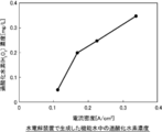
- reference example 3 it is a figure which shows the dissolved ozone concentration when water electrolysis is continued at a current density of 0.2 A/cm 2 (1.7 A) for 24 hours.
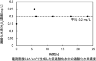
- Reference Example 3 it is a figure which shows the density
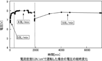
- FIG. 8 is a diagram showing a change with time in voltage in a durability test of Reference Example 4.
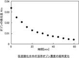
- FIG. 8 is a diagram showing how dissolved ozone concentration decreases with time in Reference Example 4.
- Reference Example 5 the concentration of ozone in the liquid phase in the current density (O 3) and hydrogen peroxide (H 2 O 2) is a diagram showing a table.
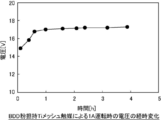
- FIG. 9 is a diagram showing a change with time in voltage in a durability test of Reference Example 5.
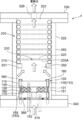
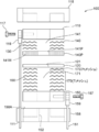
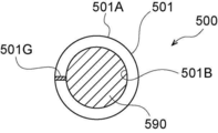
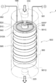
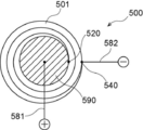
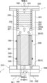
- Example 30 is a diagram showing a configuration example of Example 1, and is a diagram showing a sectional structure in which the roll-shaped electrode portion shown in FIG. 30B is enlarged and flattened. It is a figure which shows the structural example of Example 1, and is sectional drawing of a water electrolysis part. It is a figure which shows the structural example of Example 1, and is a figure which shows the structure which arrange
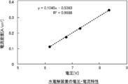
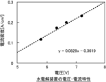
- FIG. 7 is a diagram showing voltage-current characteristics of the water electrolysis apparatus of Example 3.
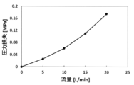
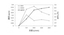
- FIG. 6 is a diagram showing the relationship between the water flow rate of the water electrolysis apparatus of Example 3 and the concentration of dissolved ozone, hydrogen peroxide concentration, and liquid phase ozone generation current efficiency in the generated accelerated oxidizing water.
- FIG. 1 is a cross-sectional view of a water electrolysis device 1 of a first reference embodiment as seen from a side surface.
- the water electrolysis device 1 electrolyzes functional water such as ozone water, hydrogen water, or accelerated oxidation water obtained by mixing ozone and hydrogen peroxide by electrolyzing water such as tap water, pure water, or ion-exchanged water (soft water). Is a device to generate.
- functional water such as ozone water, hydrogen water, or accelerated oxidation water obtained by mixing ozone and hydrogen peroxide by electrolyzing water such as tap water, pure water, or ion-exchanged water (soft water).
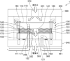
- the water electrolysis apparatus 1 is composed of a housing 300 and a water electrolysis unit 100, as shown in FIG.
- the housing 300 is formed in a cylindrical shape.
- the water electrolysis part 100 is formed in a cylindrical shape.
- the housing 300 includes an upper plate 330 which is circular when viewed from above in the figure, a lower plate 340 which is circular when viewed from below in the figure, and a cylindrical portion 350 between the upper plate 330 and the lower plate 340.
- the water electrolysis unit 100 is arranged in the housing 300.
- the housing 300 is provided with an inlet 310 and an outlet 320 so that the outside of the housing 300 and the inside of the housing 300 communicate with each other.
- the inflow port 310 is provided in the upper plate 330 of the housing 300.
- the outlet 320 is provided on the lower plate 340 of the housing 300.
- the inflow port 310 is, for example, a through hole formed in the center of the upper plate 330 of the housing 300.
- the through hole may be a screw hole, and a joint of the inflow pipe having a threaded portion may be screwed.
- the outflow port 320 is, for example, a through hole formed in the center of the lower plate 340 of the housing 300.
- the through hole may be a screw hole, and a joint of the outflow pipe having a threaded portion may be screwed.
- the inflow port 310 and the outflow port 320 are arranged so that the centers thereof coincide with or substantially coincide with the vertical center axis of the housing 300.
- the centers of the inflow port 310 and the outflow port 320 may be displaced from the vertical center axis of the housing 300.
- Raw material water flows into the inflow port 310 from the outside.
- the water electrolysis unit 100 is interposed between the inflow port 310 and the outflow port 320. From the outlet 320, the electrolyzed water generated in the water electrolysis unit 100 flows out.
- the water electrolysis unit 100 includes an anode 110, a polymer electrolyte membrane 120, an anode side electrolysis region 130, an anode side mesh electrode 140, a cathode 150, a cathode side electrolysis region 160, and a cathode side mesh electrode 170. Composed of. It should be noted that the anode 110 may be housed and held in the anode holding portion as described later with reference to FIG. 7. Similarly, the cathode 150 may be housed and held in the cathode holder.
- the anode 110 is an anode side terminal plate as an anode side electrode plate, which is electrically connected to a positive terminal of a DC power source (not shown) via a power cord 111 and an anode terminal 119.
- the polymer electrolyte membrane 120 is provided in the thickness direction of the anode 110 and has an inner opening 121 communicating with the outlet 320.
- a solid polymer electrolyte membrane such as a Nafion membrane (for example, Nafion 117 membrane; Nafion is a registered trademark) is used.
- the polymer electrolyte membrane 120 is not limited to the Nafion membrane, but various solid electrolyte membranes can be used.
- the anode side electrolysis region 130 is formed between the anode 110 and the polymer electrolyte membrane 120, and the outer peripheral opening 131 communicates with the inflow port 310.
- the anode-side mesh electrode 140 is provided in the anode-side electrolysis region 130 and has an inner opening 141 inside the anode-side electrolysis region 130.
- the inner opening 141 is an inner opening of the polymer electrolyte membrane 120. It communicates with 121.
- the cathode 150 is a cathode side terminal plate as a cathode side electrode plate, which is electrically connected to the negative terminal of the DC power source via the power cord 151 and the cathode terminal 159.
- the cathode 150 is provided in the thickness direction of the polymer electrolyte membrane 120.
- the cathode 150 has an inner opening 152 communicating with the inner opening 121 of the polymer electrolyte membrane 120.
- the cathode-side electrolysis region 160 is formed between the polymer electrolyte membrane 120 and the cathode 150, and the outer peripheral opening 161 communicates with the inflow port 310.
- the cathode-side mesh electrode 170 is provided in the cathode-side electrolysis region 160, and has an inner opening 171 inside the cathode-side electrolysis region 160.
- the inner opening 171 corresponds to the inner opening 121 of the polymer electrolyte membrane 120. It is in communication.
- the electrode surfaces of the anode side mesh electrode 140 and the cathode side mesh electrode 170 are parallel to the surface of the polymer electrolyte membrane 120.
- the anode 110, the anode-side mesh electrode 140, the polymer electrolyte membrane 120, the cathode-side mesh electrode 170, and the cathode 150 have a circular or substantially circular outer shape when viewed in a plane perpendicular to the thickness direction, that is, when viewed from above in the drawing. Is formed in.
- the inner openings 141, 121, 171, and 152 of the anode-side mesh electrode 140, the polymer electrolyte membrane 120, the cathode-side mesh electrode 170, and the cathode 150 are formed in a circular shape or a substantially circular shape.
- the inner openings 141, 121, 171, 152 are, for example, through holes formed in the centers of the anode side mesh electrode 140, the polymer electrolyte membrane 120, the cathode side mesh electrode 170 and the cathode 150, respectively.
- the anode-side mesh electrode 140, the polymer electrolyte membrane 120, the cathode-side mesh electrode 170, and the cathode 150 are formed in a ring shape or a substantially ring shape when viewed in a plane perpendicular to the thickness direction, that is, when viewed from above in the drawing.
- the centers of the inner openings 141, 121, 171, and 152 of the respective mesh openings are the same or substantially the same as the vertical central axis direction of the housing 300. It is arranged to match.
- the anode side mesh electrode 140, the polymer electrolyte membrane 120, the cathode side mesh electrode 170, and the cathode 150 are arranged such that the centers of the inner opening portions 141, 121, 171, and 152 are displaced from the vertical center axis of the housing 300. It may have been done.
- the anode side mesh electrode 140 can be composed of, for example, one mesh electrode.
- the mesh electrode 140 is arranged so that its upper surface contacts the anode 110 and its lower surface contacts the polymer electrolyte membrane 120.
- the cathode-side mesh electrode 170 can be composed of, for example, two mesh electrodes.
- the mesh electrodes of the cathode side mesh electrode 170 are arranged so that they contact each other in the thickness direction, the upper surface of the upper mesh electrode contacts the polymer electrolyte membrane 120, and the lower surface of the lower mesh electrode contacts the cathode 150. ing.
- the number of mesh electrodes forming the anode-side mesh electrode 140 can be any number of mesh electrodes of 1 or more.
- the number of mesh electrodes forming the cathode-side mesh electrode 170 can be any number of mesh electrodes of 1 or more.
- the anode-side mesh electrode 140 is sandwiched between the anode 110 and the polymer electrolyte membrane 120, and the cathode-side mesh electrode 170 is sandwiched between the polymer electrolyte membrane 120 and the cathode 150.
- the screw portion of the bolt 180 is screwed into the screw hole formed in 340.
- the water electrolysis unit 100 is fixed to the lower plate 340 of the housing 300 by screwing the bolt 180 and fastening it in the thickness direction.
- the bolt 180 may be screwed and fixed to the anode holding portion and the cathode holding portion as described later.
- a flow path 301 is formed as a gap between the anode 110 and the upper plate 330 of the housing 300. Further, a flow path 302 as a gap is formed between the anode 110 and the cathode 150 and the cylindrical portion 350 of the housing 300. In addition, a flow path 303 is formed as a gap between the cathode 150 and the lower plate 340 of the housing 300.
- the flow path 303 is sealed by an O-ring 360 as a gap between the cathode 150 and the lower plate 340 of the housing 300.
- the O-ring 360 is arranged so that the inner opening 152 of the cathode 150 is located above the inside of the O-ring 360, and the outlet 320 is located below the inside of the O-ring 360.
- anode-side mesh electrode 140 and the cathode-side mesh electrode 170 are selected according to the type of functional water to be produced.
- catalyst electrodes having excellent electrolysis activity of water are used as the anode-side mesh electrode 140 and the cathode-side mesh electrode 170.
- the catalyst electrode include metals such as Pt, Ni, and stainless steel, PbO 2, oxides such as SnO 2, IrO 2, Nb 2 O 5, TaOx doped with Ni or Sb, activated carbon, boron-doped diamond.
- a carbon electrode such as (BDD) is used.
- anode-side mesh electrode 140 and the cathode-side mesh electrode 170 in order to promote the dissolution of the gas component in water, it is preferable to use a plain weave or a structure in which a plurality of them are bundled into a twill weave. In addition, expanded metal or the like without weaving may be used.
- the anode-side mesh electrode 140 and the cathode-side mesh electrode 170 may have any structure as long as the gas (gas) is efficiently dissolved in the liquid (water) when the liquid (water) passes through the mesh surface.
- a plate-shaped (flat) and mesh-shaped (mesh) electrode such as a plain weave or a twill weave is used.
- a mesh of metal such as platinum (Pt) or metal oxide such as PbO 2 can be used as the anode mesh electrode 140.
- a mesh of a metal oxide such as IrO 2 can be used as the anode mesh electrode 140.
- IrO 2 mesh hardly produces ozone gas harmful to the human body, and thus oxygen water can be safely produced.
- a mesh electrode carrying boron-doped diamond (BDD) powder or an electrode formed with boron-doped diamond (BDD) on a perforated Nb substrate When generating accelerated oxidized water in which ozone and hydrogen peroxide coexist, a mesh electrode carrying boron-doped diamond (BDD) powder or an electrode formed with boron-doped diamond (BDD) on a perforated Nb substrate.
- BDD boron-doped diamond
- BDD boron-doped diamond
- BDD boron-doped diamond
- the water electrolysis apparatus 1 configured as described above operates as follows.
- Raw water is supplied to the inflow port 310 from a raw water source, such as a storage tank (not shown) or a water tap.
- a voltage is applied between the anode 110 and the cathode 150 by the DC power supply.
- current flows from the positive terminal of the DC power source to the negative terminal of the DC power source through the power cord 111, the anode 110, the cathode 150, and the power cord 151, and the anode side electrolysis region 130 and the cathode side electrolysis region 160 of the water electrolysis unit 100. Water electrolysis is carried out.
- FIG. 3A is a diagram illustrating the flow of water in the water electrolysis unit 100.
- description will be given with reference to FIG.
- the raw material water that has flowed into the inflow port 310 flows into the anode-side electrolysis region 130 via the flow channel 301, the flow channel 302, and the outer peripheral opening 131 of the anode-side electrolysis region 130.
- FIG. 2A is a diagram illustrating the flow of water in the anode-side electrolysis region 130.
- description will be given with reference to FIGS. 1 and 3A.
- a radial flow is formed from the outer peripheral opening 131 toward the inner opening 141 of the anode-side mesh electrode 140.
- a horizontal flow is formed with respect to the electrode surface of the anode-side mesh electrode 140.
- a gas such as ozone and oxygen generated by water electrolysis in the anode side electrolysis region 130 and hydrogen peroxide are dissolved in the raw material water in the anode side electrolysis region 130 to generate anode side electrolysis water.
- the anode-side electrolyzed water generated in the anode-side electrolysis region 130 flows into the inner opening 141 of the anode-side mesh electrode 140.
- the raw material water supplied to the inflow port 310 flows into the cathode side electrolysis region 160 via the flow channel 301, the flow channel 302, and the outer peripheral opening 161 of the cathode side electrolysis region 160.
- a radial flow is formed from the outer peripheral opening 161 toward the inner opening 171 of the cathode side mesh electrode 170.
- a horizontal flow is formed with respect to the electrode surface of the cathode side mesh electrode 170.
- the hydrogen gas, hydrogen peroxide, etc. generated by water electrolysis in the cathode side electrolysis region 160 are dissolved in the raw material water in the cathode side electrolysis region 160 to generate cathode side electrolysis water.
- the cathode-side electrolyzed water generated in the cathode-side electrolysis region 160 flows into the inner opening 171 of the cathode-side mesh electrode 170.
- the anode-side electrolyzed water that has flowed into the inside opening 141 of the anode-side mesh electrode 140 is introduced into the inside opening 171 of the cathode-side mesh electrode 170 through the inside opening 121 of the polymer electrolyte membrane 120, and the cathode-side electrolysis is performed. Join the water.
- the combined electrolyzed water flows out to the outside through the inner opening 152 of the cathode 150, the flow path 303, and the outflow port 320.
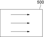
- FIG. 2B is a diagram illustrating a flow of water when the water electrolysis unit is configured using the conventional square mesh electrode 500.
- the electrode area of the mesh electrode 500 is 8 cm 2 , the width of the water inlet is 2 cm, and the depth in the water flow direction is 4 cm. In this case, the inflow cross-sectional area of water is “2 cm ⁇ thickness of mesh electrode”.
- the anode side mesh electrode 140 having the same electrode area 8 cm 2 as the square mesh electrode 500 when used and the inner opening 141 has a diameter of 1 cm, The cross-sectional area of inflow of water becomes “3.14 cm ⁇ thickness of mesh electrode” or more. Since the inflow cross-sectional area of water increases from the inner side to the outer side of the anode-side mesh electrode 140, the resistance when flowing water decreases. Therefore, as compared with the square mesh electrode 500, the cross-sectional area of inflow of water is large even though the electrode area is the same, a water electrolysis section with less pressure loss can be configured, and a large amount of water can be flowed. The same applies to the cathode side mesh electrode 170.
- a flow is formed in the radial direction between the outer periphery of the mesh electrode and the inner opening. Therefore, the inflow cross-sectional area of water can be made larger than in the case of using the conventional square mesh electrode. Therefore, the pressure loss of water passing through the water electrolysis device is reduced, and a large flow rate of functional water can be generated with a small device. In addition, a fluid dead part and a gas pool are unlikely to occur. Therefore, water electrolysis can be efficiently performed with a smaller number of pipes than in the case of using a conventional square mesh electrode.
- the inlet side and the outlet side of water are made common on the anode side and the cathode side, and the inflow port 310 and the outflow port 320 are each one, and the water inflow pipe and the outflow pipe are each one. can do. Therefore, it is possible to further reduce the number of pipes and save space.
- the electrolyzed water on the anode side and the electrolyzed water on the cathode side can be combined and used, water can be saved.
- the anode side mesh electrode 140, the polymer electrolyte membrane 120, and the cathode side mesh electrode 170 may have any shape.
- the outer peripheral shape of the anode-side mesh electrode 140, the polymer electrolyte membrane 120, and the cathode-side mesh electrode 170 and the shape of the inner opening may be a quadrangle, a triangle, or an ellipse.
- the shape of the housing 300 is not limited to the cylindrical shape, and may be a quadrangle, a triangle, an ellipse, or the like.
- the water electrolysis apparatus 1 shown in FIG. 1 has a structure in which the flow of water flows from the top to the bottom in the figure.
- FIG. 3B is a diagram illustrating a flow of water in the water electrolysis unit 100 according to the second reference embodiment.
- the same components as those shown in FIG. 1 are designated by the same reference numerals, and a configuration different from the first reference embodiment will be described.
- the inflow port 310 has the inner opening 171 of the cathode-side mesh electrode 170, the inner opening 121 of the polymer electrolyte membrane 120, and the anode-side mesh electrode 140 via the inner opening 152 of the cathode 150.
- the outer peripheral opening 131 of the anode-side electrolysis region 130 and the outer peripheral opening 161 of the cathode-side electrolysis region 160 communicate with the outflow port 320.
- the raw material water flowing into the inflow port 310 flows into the cathode side electrolysis region 160 through the inside opening 152 of the cathode 150 and the inside opening 171 of the cathode side mesh electrode 170. Further, the raw material water flows into the anode side electrolysis region 130 through the inside opening 171 of the cathode side mesh electrode 170, the inside opening 121 of the polymer electrolyte membrane 120, and the inside opening 141 of the anode side mesh electrode 140.
- a radial flow is formed from the inner opening 171 of the cathode-side mesh electrode 170 toward the outer peripheral opening 161.
- a horizontal flow is formed with respect to the electrode surface of the cathode side mesh electrode 170.
- the hydrogen gas, hydrogen peroxide, etc. generated by water electrolysis in the cathode side electrolysis region 160 are dissolved in the raw material water in the cathode side electrolysis region 160 to generate cathode side electrolysis water.
- the cathode-side electrolyzed water generated in the cathode-side electrolysis region 160 flows out from the outer peripheral opening 161 of the cathode-side electrolysis region 160.
- anode-side electrolysis region 130 a radial flow from the inner opening 141 of the anode-side mesh electrode 140 toward the outer peripheral opening 131 is formed.
- a horizontal flow is formed with respect to the electrode surface of the anode-side mesh electrode 140.
- Gases such as ozone and oxygen generated by water electrolysis in the anode-side electrolysis region 130 and hydrogen peroxide are dissolved in raw material water in the anode-side electrolysis region 130 to generate anode-side electrolysis water.
- the anode-side electrolyzed water generated in the anode-side electrolysis area 130 flows out from the outer peripheral opening 131 of the anode-side electrolysis area 130.
- the anode-side electrolyzed water that has flowed outward from the outer peripheral opening 131 of the anode-side electrolysis region 130 joins with the cathode-side electrolyzed water that has flowed outward from the outer peripheral opening 161 of the cathode-side electrolysis region 160.
- the combined electrolyzed water flows out through the outlet 320.
- a flow is formed in the radial direction between the outer periphery of the mesh electrode and the inner opening, so that the pressure loss of water passing through the water electrolysis device is reduced. Is small, and a large flow of functional water can be generated with a small device. Further, since a dead part of the fluid and a gas reservoir are less likely to occur, water electrolysis can be efficiently performed with a smaller number of pipes than in the case of using a conventional square mesh electrode. Since the water inlet and the water outlet are shared between the anode side and the cathode side, the number of pipes can be further reduced, and space can be saved. In addition, since the electrolyzed water on the anode side and the electrolyzed water on the cathode side can be combined and used, water can be saved.
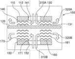
- FIG. 4A is a diagram illustrating a flow of water in the water electrolysis unit 100 according to the third reference embodiment.
- the same components as those shown in FIG. 1 are designated by the same reference numerals, and the configuration different from that of the first reference embodiment will be described.
- a first inflow port 310A and a second inflow port 310B are provided, and a first outflow port 320A and a second outflow port 320B are provided.
- the first inlet 310A communicates with the inner opening 141 of the anode-side mesh electrode 140 via the inner opening 112 of the anode 110.
- the second inflow port 310B communicates with the inner opening 171 of the cathode side mesh electrode 170 via the inner opening 152 of the cathode 150.
- the outer peripheral opening 131 of the anode-side electrolysis region 130 communicates with the first outlet 320A. Further, the outer peripheral opening 161 of the cathode-side electrolysis region 160 communicates with the second outlet 320B.
- the raw material water that has flowed into the first inflow port 310A flows into the anode-side electrolysis region 130 via the inner opening 141 of the anode-side mesh electrode 140.
- the raw material water that has flowed into the second inflow port 310B flows into the cathode-side electrolysis region 160 through the inner opening 152 of the cathode 150 and the inner opening 171 of the cathode-side mesh electrode 170.
- a radial flow is formed from the inner opening 141 of the anode-side mesh electrode 140 toward the outer peripheral opening 131.
- a horizontal flow is formed with respect to the electrode surface of the anode-side mesh electrode 140.
- Gases such as ozone and oxygen generated by water electrolysis in the anode-side electrolysis region 130 and hydrogen peroxide are dissolved in raw material water in the anode-side electrolysis region 130 to generate anode-side electrolysis water.
- the anode-side electrolyzed water generated in the anode-side electrolysis area 130 flows out from the outer peripheral opening 131 of the anode-side electrolysis area 130.
- the anode-side electrolyzed water that has flowed outward from the outer peripheral opening 131 of the anode-side electrolysis region 130 flows out to the outside via the first outlet 320A.
- a radial flow is formed from the inner opening 171 of the cathode-side mesh electrode 170 toward the outer peripheral opening 161.
- a horizontal flow is formed with respect to the electrode surface of the cathode side mesh electrode 170.
- the hydrogen gas, hydrogen peroxide, etc. generated by water electrolysis in the cathode side electrolysis region 160 are dissolved in the raw material water in the cathode side electrolysis region 160 to generate cathode side electrolysis water.
- the cathode-side electrolyzed water generated in the cathode-side electrolysis region 160 flows out from the outer peripheral opening 161 of the cathode-side electrolysis region 160.
- the cathode-side electrolyzed water that has flowed outward from the outer peripheral opening 161 of the cathode-side electrolysis region 160 flows out to the outside via the second outlet 320B.
- a flow is formed in the radial direction between the outer periphery of the mesh electrode and the inner opening, so that the water electrolysis device can be used.
- the pressure loss of the passing water is reduced, and a large amount of functional water can be generated with a small device.
- water electrolysis can be efficiently performed with a smaller number of pipes than in the case of using a conventional square mesh electrode.
- the electrolyzed water on the anode side and the electrolyzed water on the cathode side are generated separately without joining, the functions of ozone water, hydrogen water, etc. with a higher concentration than the case of joining the electrolyzed water on the anode side and the cathode side Water can be produced.
- a configuration is also possible in which a flow is formed in the radial direction from the outer periphery of the mesh electrode toward the inner opening.
- FIG. 4B is a diagram illustrating a flow of water in the water electrolysis unit 100 according to the fourth reference embodiment.
- the same components as those shown in FIG. 1 are designated by the same reference numerals, and a configuration different from the first reference embodiment will be described.
- a first inflow port 310A and a second inflow port 310B are provided, and a first outflow port 320A and a second outflow port 320B are provided.
- the first inflow port 310A communicates with the outer peripheral opening 131 of the anode-side electrolysis region 130.
- the second inflow port 310B communicates with the outer peripheral opening 161 of the cathode-side electrolysis region 160.
- the first outlet 320A communicates with the inner opening 141 of the anode-side mesh electrode 140 via the inner opening 112 of the anode 110.
- the second outlet 320B communicates with the inner opening 171 of the cathode-side mesh electrode 170 via the inner opening 152 of the cathode 150.
- the raw material water that has flowed into the first inlet 310A flows into the anode-side electrolysis region 130 through the outer peripheral opening 131 of the anode-side electrolysis region 130.
- a radial flow is formed from the outer peripheral opening 131 toward the inner opening 141 of the anode-side mesh electrode 140.
- a horizontal flow is formed with respect to the electrode surface of the anode-side mesh electrode 140.
- Gases such as ozone and oxygen generated by water electrolysis in the anode-side electrolysis region 130 and hydrogen peroxide are dissolved in raw material water in the anode-side electrolysis region 130 to generate anode-side electrolysis water.
- the anode-side electrolyzed water generated in the anode-side electrolysis region 130 flows out to the outside via the inside opening 141 of the anode side mesh electrode 140, the inside opening 112 of the anode 110, and the first outlet 320A.
- the raw material water that has flowed into the second inflow port 310B flows into the cathode-side electrolysis region 160 through the outer peripheral opening 161 of the cathode-side electrolysis region 160.
- a radial flow is formed from the outer peripheral opening 161 toward the inner opening 171 of the cathode side mesh electrode 170.
- a horizontal flow is formed with respect to the electrode surface of the cathode side mesh electrode 170.
- the hydrogen gas, hydrogen peroxide, etc. generated by water electrolysis in the cathode side electrolysis region 160 are dissolved in the raw material water in the cathode side electrolysis region 160 to generate cathode side electrolysis water.
- the cathode-side electrolyzed water generated in the cathode-side electrolysis region 160 flows out to the outside via the inside opening 171 of the cathode side mesh electrode 170, the inside opening 152 of the cathode 150, and the second outlet 320B.
- a flow is formed in the radial direction between the outer periphery of the mesh electrode and the inner opening. Therefore, the pressure loss of water passing through the water electrolysis device is reduced, and a large flow rate of functional water can be generated with a small device. Further, since a dead part of the fluid and a gas reservoir are less likely to occur, water electrolysis can be efficiently performed with a smaller number of pipes than in the case of using a conventional square mesh electrode. In addition, since the electrolyzed water on the anode side and the electrolyzed water on the cathode side are generated separately without joining, the functions of ozone water, hydrogen water, etc. with a higher concentration than the case of joining the electrolyzed water on the anode side and the cathode side Water can be produced.
- the fifth reference embodiment has the same configuration as the third reference embodiment on the anode side, and a flow is formed in the radial direction from the inner opening of the mesh electrode toward the outer circumference.
- the flow is formed in the radial direction from the outer periphery of the mesh electrode toward the inner opening, which is configured similarly to the fourth reference embodiment.
- the raw material water that has flowed into the first inflow port 310A flows into the anode-side electrolysis region 130 via the inner opening 141 of the anode-side mesh electrode 140.
- a radial flow is formed from the inner opening 141 of the anode-side mesh electrode 140 toward the outer peripheral opening 131.
- a horizontal flow is formed with respect to the electrode surface of the anode-side mesh electrode 140.
- Gases such as ozone and oxygen generated by water electrolysis in the anode-side electrolysis region 130 and hydrogen peroxide are dissolved in raw material water in the anode-side electrolysis region 130 to generate anode-side electrolysis water.
- the anode-side electrolyzed water generated in the anode-side electrolysis area 130 flows out from the outer peripheral opening 131 of the anode-side electrolysis area 130.
- the anode-side electrolyzed water that has flowed outward from the outer peripheral opening 131 of the anode-side electrolysis region 130 flows out to the outside via the first outlet 320A.
- the raw material water that has flowed into the second inflow port 310B flows into the cathode-side electrolysis region 160 through the outer peripheral opening 161 of the cathode-side electrolysis region 160.
- a radial flow is formed from the outer peripheral opening 161 toward the inner opening 171 of the cathode side mesh electrode 170.
- a horizontal flow is formed with respect to the electrode surface of the cathode side mesh electrode 170.
- the hydrogen gas, hydrogen peroxide, etc. generated by water electrolysis in the cathode side electrolysis region 160 are dissolved in the raw material water in the cathode side electrolysis region 160 to generate cathode side electrolysis water.
- the cathode-side electrolyzed water generated in the cathode-side electrolysis region 160 flows out to the outside via the inside opening 171 of the cathode side mesh electrode 170, the inside opening 152 of the cathode 150, and the second outlet 320B.
- the radial direction is provided between the outer periphery of the mesh electrode and the inner opening. Since the flow is formed in, the pressure loss of water passing through the water electrolysis device is reduced, and a large flow rate of functional water can be generated with a small device. Further, since a dead part of the fluid and a gas reservoir are less likely to occur, water electrolysis can be efficiently performed with a smaller number of pipes than in the case of using a conventional square mesh electrode. In addition, since the electrolyzed water on the anode side and the electrolyzed water on the cathode side are generated separately without joining, the functions of ozone water, hydrogen water, etc. with a higher concentration than the case of joining the electrolyzed water on the anode side and the cathode side Water can be produced.
- the sixth reference embodiment is similar to the third reference embodiment, the fourth reference embodiment, and the fifth reference embodiment, in which the water inlet and the water outlet are separately provided on the anode side and the cathode side, and the anode-side electrolyzed water and the cathode are formed.
- This is an embodiment of a two-chamber type water electrolysis section that separately produces side electrolyzed water without joining.
- the sixth reference embodiment has the same configuration as the fourth reference embodiment on the anode side, and a flow is formed in the radial direction from the outer periphery of the mesh electrode toward the inner opening.
- the flow is formed in the radial direction from the inner opening of the mesh electrode toward the outer periphery in the same configuration as in the third embodiment.
- the raw material water that has flowed into the first inlet 310A flows into the anode-side electrolysis region 130 through the outer peripheral opening 131 of the anode-side electrolysis region 130.
- a radial flow is formed from the outer peripheral opening 131 toward the inner opening 141 of the anode-side mesh electrode 140.
- a horizontal flow is formed with respect to the electrode surface of the anode-side mesh electrode 140.
- Gases such as ozone and oxygen generated by water electrolysis in the anode-side electrolysis region 130 and hydrogen peroxide are dissolved in raw material water in the anode-side electrolysis region 130 to generate anode-side electrolysis water.
- the anode-side electrolyzed water generated in the anode-side electrolysis region 130 flows out to the outside via the inside opening 141 of the anode side mesh electrode 140, the inside opening 112 of the anode 110, and the first outlet 320A.
- the raw material water that has flowed into the second inlet 310B flows into the cathode-side electrolysis region 160 through the inner opening 152 of the cathode 150 and the inner opening 171 of the cathode-side mesh electrode 170.
- a radial flow is formed from the inner opening 171 of the cathode-side mesh electrode 170 toward the outer peripheral opening 161.
- a horizontal flow is formed with respect to the electrode surface of the cathode side mesh electrode 170.
- the hydrogen gas, hydrogen peroxide, etc. generated by water electrolysis in the cathode side electrolysis region 160 are dissolved in the raw material water in the cathode side electrolysis region 160 to generate cathode side electrolysis water.
- the cathode-side electrolyzed water generated in the cathode-side electrolysis region 160 flows out from the outer peripheral opening 161 of the cathode-side electrolysis region 160.
- the cathode-side electrolyzed water that has flowed outward from the outer peripheral opening 161 of the cathode-side electrolysis region 160 flows out to the outside via the second outlet 320B.
- the outer circumference and the inner opening of the mesh electrode are similar to the first reference embodiment, the second reference embodiment, the third reference embodiment, the fourth reference embodiment, and the fifth reference embodiment. Since a flow is formed in a radial direction between and, the pressure loss of water passing through the water electrolysis device is reduced, and a large flow rate of functional water can be generated with a small device. Further, since a dead part of the fluid and a gas reservoir are less likely to occur, water electrolysis can be efficiently performed with a smaller number of pipes than in the case of using a conventional square mesh electrode.
- the electrolyzed water on the anode side and the electrolyzed water on the cathode side are generated separately without joining, the functions of ozone water, hydrogen water, etc. with a higher concentration than the case of joining the electrolyzed water on the anode side and the cathode side Water can be produced.
- FIG. 6 shows a configuration example of the fourth reference mode shown in FIG. 4B as a seventh reference mode.
- the housing 300 of the water electrolysis device 1 of the seventh reference embodiment is configured to include an anode side flange 330 as an upper plate and a cathode side flange 340 as a lower plate.
- a flange protrusion 330F facing the flange protrusion 340F of the cathode flange 340 is formed on the outer periphery of the anode flange 330.
- An annular groove that accommodates an O-ring 370A that contacts the outer periphery of the polymer electrolyte membrane 120 is formed on the opposing surface of the flange protrusion 330F.
- a first inlet 310A is formed on the side wall of the flange protrusion 330F.
- An annular groove recess 332 that communicates with the first inflow port 310A is formed inside the flange protrusion 330F.
- a protrusion 330D that abuts on the anode-side mesh electrode 140 is formed inside the groove recess 332.
- An annular concave portion 331 that accommodates the annular anode 110 is formed on the convex portion 330D.
- a first outlet 320A is formed in the center of the convex portion 330D and in the center of the inside of the concave portion 331.
- a flange convex portion 340F facing the flange convex portion 330F of the anode side flange 330 is formed on the outer circumference of the cathode side flange 340.
- An annular groove that accommodates the O-ring 370B that contacts the outer periphery of the polymer electrolyte membrane 120 is formed on the opposing surface of the flange protrusion 340F.
- a second inlet 310B is formed on the side wall of the flange protrusion 340F.
- An annular groove recess 342 communicating with the second inflow port 310B is formed inside the flange protrusion 340F.
- a protrusion 340D that contacts the cathode-side mesh electrode 170 is formed inside the groove recess 342.
- An annular recess 341 for accommodating the annular cathode 150 is formed on the protrusion 340D.
- a second outlet 320B is formed in the center of the convex portion 340D and in the center of the inside of the concave portion 341.
- the flange protrusion 330F of the anode side flange 330 and the flange protrusion 340F of the cathode side flange 340 are fastened with bolts 181.
- the chamber on the anode side and the chamber on the cathode side are partitioned by the polymer electrolyte membrane 120 and sealed by O-rings 370A and O-rings 370B, respectively.
- the distance (depth) from the facing surface of the flange protrusion 330F of the anode side flange 330 to the contact surface of the protrusion 330D defines the number of anode side mesh electrodes 140 that can be accommodated. For example, when accommodating five anode side mesh electrodes 140 having a thickness of 0.3 mm, the distance (depth) may be set to 1.5 mm. Similarly, the distance (depth) from the facing surface of the flange convex portion 340F of the cathode side flange 340 to the contact surface of the convex portion 340D defines the number of cathode side mesh electrodes 170 accommodated.
- the anode side mesh electrode 140 is composed of three sheets
- the cathode side mesh electrode 170 is composed of six sheets
- the number of the cathode side mesh electrodes 170 is twice the number of the anode side mesh electrodes 140
- the cathode side chamber is provided. It is possible to implement a flow rate higher than that in the chamber on the anode side. By flowing a larger flow rate in the cathode-side chamber than in the anode-side chamber, the pH rise of the cathode-side electrolyzed water is suppressed and the deposition of minerals on the cathode side is suppressed. A reference mode for suppressing the electrodeposition of minerals will be described later.
- FIG. 6 can be similarly applied to the third reference embodiment shown in FIG. 4A, the fifth reference embodiment shown in FIG. 5A, and the sixth reference embodiment shown in FIG. 5B.
- cathode side mesh electrodes 170 By changing the type and number of cathode side mesh electrodes 170 and the conditions of water electrolysis (flow rate and current density of cathode side electrolyzed water), the generation rate of hydroxide ion OH ⁇ is adjusted, and the pH of cathode side electrolyzed water is increased. Can be suppressed.
- a platinum (Pt) mesh having a hydrogen overvoltage of almost zero or a stainless steel mesh having a hydrogen overvoltage of about 0.1 V is used as the cathode-side mesh electrode 170 to carry out water electrolysis at a low current density.
- the increase in the pH of the cathode-side electrolyzed water is suppressed to a minimum, and the decrease in the saturated solubility of mineral components such as calcium carbonate CaCO 3 and magnesium hydroxide Mg(OH) 2 due to the increase in pH is suppressed. This can prevent the deposition of these minerals on the cathode side. By performing such an operation, it becomes possible to stably operate the water electrolysis apparatus 1 for a long time.
- platinum (Pt) mesh or stainless steel mesh for the cathode side mesh electrode 170, to further reduce the current density, to increase the flow rate of the cathode side electrolyzed water, and the like. This prevents the deposition of minerals.
- the confluence type water electrolysis apparatus of the first reference embodiment and the second reference embodiment is used, in order to prevent the deposition of minerals, the current density is low, and It is necessary to perform the operation with a large flow rate of the cathode-side electrolyzed water. Therefore, it becomes difficult to increase the concentration of ozone water.
- the ozone water generated on the anode side does not join with the cathode-side electrolyzed water, and It can be taken out by itself. For this reason, when hard water is used as the raw material water, even if the operation in which the flow rate of the cathode-side electrolyzed water is high is performed in order to prevent the deposition of minerals, the anode side is not affected. Therefore, it becomes easy to increase the concentration of ozone water.
- cathode side mesh electrode 170 Regardless of the material of the cathode side mesh electrode 170, it is possible to optimize the conditions of water electrolysis to control the pH rise of the cathode side electrolyzed water and prevent the deposition of minerals on the cathode side for long-term operation. Is important in doing.
- the hydrogen peroxide generation reaction on the anode side can be expressed by the following equation (2).
- platinum (Pt) mesh having a low hydrogen overvoltage may be used as the cathode-side mesh electrode 170 that contacts the surface of the polymer electrolyte membrane 120.
- the voltage applied to the electrodes is suppressed and the power efficiency of hydrogen generation can be increased.
- the Pt mesh having a low hydrogen overvoltage as the cathode side mesh electrode 170, it is possible to suppress the generation of the hydroxide ion OH ⁇ according to the formula (1). Therefore, the increase in the pH of the cathode-side electrolyzed water can be suppressed without increasing the flow rate of the cathode-side electrolyzed water, and the electrodeposition of minerals can be prevented.
- an electrode having a high hydrogen overvoltage such as titanium (Ti) or boron-doped diamond (BDD) may be used. These catalyst electrodes are also placed in contact with the polymer electrolyte membrane 120.
- a boron-doped diamond (BDD) electrode has a hydrogen overvoltage of about -1 V, so that hydrogen peroxide can be efficiently generated on the cathode side.
- the number of mesh electrodes installed on the anode side and the cathode side may be determined by the ratio of the amount of water flowing to the anode side and the cathode side. For example, when it is desired to flow twice the amount of water on the cathode side as on the anode side, the total number of mesh electrodes installed on the cathode side should be twice the total number of mesh electrodes installed on the anode side. As a result, the amount of water to the cathode side can be secured, so that it is possible to suppress the pH rise of the cathode side electrolyzed water. Then, it is possible to prevent mineral components such as calcium carbonate CaCO 3 and magnesium hydroxide Mg(OH) 2 generated by water electrolysis from depositing on the cathode side.
- magnesium hydroxide Mg(OH) 2 When the pH of the cathode-side electrolyzed water rises to 9 or higher, the saturated solubility of magnesium hydroxide Mg(OH) 2 in water decreases. For this reason, magnesium hydroxide Mg(OH) 2 will be deposited on the electrode on the cathode side where the pH is locally low. Further, the concentration of CO 2 3- ions in water as a raw material of calcium carbonate CaCO 3 is determined by the dissociation equilibrium of H 2 CO 3 carbonate.
- FIG. 7 is an exploded view showing a configuration example of the water electrolysis unit 100 arranged in the housing 300 of FIG.
- the annular anode 110 is housed in an annular recess 118A formed in the anode holder 118.
- the annular cathode 150 is housed in an annular recess 158A formed in the cathode holding portion 158.
- the anode holder 118 and the cathode holder 158 are made of acrylic resin, for example.
- the anode 110 is configured as a terminal plate made of titanium (Ti), for example.
- the cathode 150 is configured as a terminal plate made of stainless steel, for example.
- An anode terminal 119 configured as a crimp terminal is screwed and fixed to the anode 110 with, for example, a screw 117 (for example, an M3 screw).
- a negative terminal 159 configured as a crimp terminal is screwed and fixed to the cathode 150, for example, with a screw 157 (M3 screw).
- the substrate electrode 140P is formed with an inner opening 141P communicating with the inner opening 121 of the polymer electrolyte membrane 120 and the inner opening 141 of the anode-side mesh electrode 140.
- the substrate electrode 140P is a substrate electrode in which a plurality of through holes 141H are formed in the thickness direction, is made of niobium (Nb), and a thin film of boron-doped diamond (BDD) is formed on the niobium (Nb) substrate. There is.
- the substrate electrode 140P is arranged so as to contact the polymer electrolyte membrane 120.
- a round through hole having a diameter of 1 mm or a square through hole having a side of 1 mm formed at a pitch of about 2 mm is used as the substrate electrode 140P.
- anode-side mesh electrode 140 to be arranged on the anode side, at least one mesh electrode may be arranged in addition to the substrate electrode 140P in order to secure the flow passage cross-sectional area.
- titanium (Ti) mesh electrodes for example, 80 mesh are provided as the cathode side mesh electrode 170.
- the reason for selecting mesh electrodes made of the above materials is to generate accelerated oxidation water in which ozone and hydrogen peroxide coexist.
- the water electrolysis unit 100 shown in FIG. 7 is arranged in the housing 300 shown in FIG.
- the anode-side mesh electrode 140 and the substrate electrode 140P are sandwiched between the anode 110 and the polymer electrolyte membrane 120, and the cathode-side mesh electrode 170 is sandwiched between the polymer electrolyte membrane 120 and the cathode 150.
- the screw portion of the bolt 180 (for example, M3 screw) is screwed into the screw hole formed in the lower plate 340 of the housing 300.
- the water electrolysis unit 100 is fixed to the lower plate 340 of the housing 300 by screwing the bolt 180 and fastening it in the thickness direction.
- the material of the casing 300 is preferably Teflon (registered trademark), which has ozone resistance.
- Teflon registered trademark
- the material of the housing 300 may be made of a general-purpose resin such as acrylic or polypropylene.
- acrylic resin it does not deteriorate even if it is exposed to ozone water having a concentration of about 10 mg/L for several years.
- Teflon registered trademark
- Teflon Ted trademark
- An inflow port 310 and an outflow port 320 are opened in the central portions of the upper plate 330 and the lower plate 340 of the housing 300, respectively, and a female screw for connecting a joint is cut on the inner peripheral surface.
- the housing 300 is made of transparent acrylic resin in this embodiment.
- a joint is connected to each of the inflow port 310 and the outflow port 320, and a pipe or a tube is connected to the joint.
- the housing 300 has, for example, an inner diameter of 50 mm, and the distance between the upper plate 330 and the lower plate 340 is 35 mm.
- a cylindrical water electrolysis unit 100 having an outer diameter of 47 mm and a height of 22 mm shown in FIG. 7 is arranged in the housing 300.
- the thickness of each of the anode 110 and the cathode 150 can be set to 6 mm, for example.
- the anode side mesh electrode 140, the substrate electrode 140P, and the cathode side mesh electrode 170 can have an outer diameter of 3.5 cm and an inner diameter (diameter of the inner opening) of 1.1 cm. At this time, the area of the mesh electrode and the substrate electrode is about 8.6 cm 2 .
- a substrate electrode 140P having a thickness of 0.5 mm can be used.
- a 0.2 mm thick Nafion 117 membrane or the like can be used.
- the gap between the water electrolysis unit 100 and the lower plate 340 of the housing 300 is sealed by an O-ring 360.
- power cords 111 and 151 each having a diameter of about 3 mm are electrically connected to the anode 110 and the cathode 150 of the water electrolysis unit 100, and the power cords are provided through holes 348 and 349 formed in the housing 300. 111 and 151 are drawn out respectively. The gaps between the power cords 111 and 151 and the holes 348 and 349 are sealed with an adhesive or the like.
- the power cords 111 and 151 are electrically connected to the positive terminal and the negative terminal of the variable power source or the constant voltage DC power source, respectively.
- the flow rate ratio of the electrolyzed water on the anode side to the electrolyzed water on the cathode side is determined by the ratio of the flow passage cross-sectional areas of the outer peripheral opening 131 of the anode side electrolytic region 130 and the outer peripheral opening 161 of the cathode side electrolytic region 160, that is, the ratio of the number of mesh electrodes. It is determined accordingly.
- a substrate electrode 140P is used in addition to the mesh electrode.
- the cross-sectional area portion corresponding to the substrate electrode 140P blocks the water and is not included in the flow channel cross-sectional area. Therefore, the flow rate ratio of the electrolyzed water on the anode side to the electrolyzed water on the cathode side is determined by the number ratio of the mesh electrodes excluding the substrate electrode 140P.
- the anode-side electrolyzed water generated on the anode side and the cathode-side electrolyzed water generated on the cathode side join together and flow out to the outside through the inner opening 152 of the cathode holding unit 158. It is possible to obtain functional water in which three kinds of gases of ozone, oxygen and hydrogen and hydrogen peroxide are dissolved.
- BDD boron-doped diamond
- Ti titanium
- stainless steel or boron-doped diamond is used as a catalyst electrode that contacts the polymer electrolyte membrane 120.
- boron-doped diamond is used as a catalyst electrode that contacts the polymer electrolyte membrane 120.
- a mesh electrode carrying diamond BDD
- hydrogen peroxide can be generated at both electrodes. Thereby, the concentration of hydrogen peroxide can be increased.
- the polymer electrolyte membrane 120 partitions the anode-side electrolyzed water and the cathode-side electrolyzed water existing in the anode-side electrolysis area 130 and the cathode-side electrolysis area 160. Therefore, electrolyzed water does not move back and forth between the anode side and the cathode side.
- the electrolyzed water on the anode side and the electrolyzed water on the cathode side merge at the inner opening in the center of the water electrolysis section 100 and flow out from the inner opening 152 of the cathode holding section 158 on the lower side in the drawing. Therefore, reduction of ozone and oxygen by hydrogen ions (H + ) during the water electrolysis reaction is suppressed.
- the water electrolysis apparatus 1 having the configuration in which the water electrolysis unit 100 shown in FIG. 7 is arranged in the housing 300 shown in FIG. 1, water is supplied from above in the drawing, but water may be supplied from below in the drawing.
- the direction of supplying water is arbitrary.
- the water electrolysis unit 100 may be arranged sideways, and the angle of arrangement may be set arbitrarily. Therefore, the water electrolysis device 1 can be connected to a rubber hose or the like and used for showers or water sprinkling.
- FIG. 8 is an exploded view which shows the structural example of the water electrolysis part 400 of the 10th reference embodiment.
- the water electrolysis unit 400 is configured by interposing two water electrolysis units 100 and 100′ between the inflow port 310 and the outflow port 320.
- the water electrolysis unit 400 is vertically symmetrical about the symmetry axis C in the figure.
- a water electrolysis section 100 (referred to as one electrolysis section 100) similar to the water electrolysis section 100 shown in FIG. 7 is provided.
- a water electrolysis unit 100′ (referred to as the other electrolysis unit) similar to the water electrolysis unit 100 shown in FIG. 7 is provided.
- the components of the other water electrolysis unit 100 ′ the same components as those of the one water electrolysis unit 100 are given a dash.
- the flow of water in the anode-side electrolysis region 130 and the cathode-side electrolysis region 160 of one water electrolysis unit 100 and the flow of water in the anode-side electrolysis region 130′ and the cathode-side electrolysis region 160′ of the other water electrolysis unit 100′ are They are arranged in parallel.
- the cathode 150 of the one water electrolysis unit 100 is common to the cathode of the other water electrolysis unit 100'.
- the structure of one of the water electrolysis units 100 is as follows.
- the annular anode 110 is housed in an annular recess 118A formed in the anode holding portion 118.
- An anode terminal 119 configured as a crimp terminal is screwed and fixed to the anode 110, for example, with a screw 117.
- a negative terminal 159 configured as a crimping terminal is screwed and fixed to the cathode 150, for example, with a screw 157.
- the substrate electrode 140P is formed with an inner opening 141P communicating with the inner opening 121 of the polymer electrolyte membrane 120 and the inner opening 141 of the anode-side mesh electrode 140.
- the substrate electrode 140P is arranged so as to be in contact with the polymer electrolyte membrane 120.
- two mesh electrodes are provided as the cathode side mesh electrode 170.
- the configuration of the other water electrolysis section 100' is as follows.
- the same constituent elements as the constituent elements of one water electrolysis section 100 are symmetrically arranged as the constituent elements of the other water electrolysis section 100′ with the symmetry axis C as the center of symmetry.
- an inner opening 115 communicating with the outflow port 320 and the inner opening 141 ′ of the anode-side mesh electrode 140 ′ is formed in the anode holding part 118 ′ of the other water electrolysis part 100 ′.
- the water electrolysis unit 400 shown in FIG. 8 may be arranged in the housing 300 shown in FIG. 1 to configure the water electrolysis apparatus 1.
- water may be supplied to the water electrolysis unit 400 shown in FIG. 8 from above in the drawing, or may be supplied from below in the drawing.
- the direction of supplying water to the water electrolysis unit 400 is arbitrary.
- the water electrolysis unit 400 may be arranged sideways, and the angle of arrangement may be set arbitrarily.
- the water electrolysis unit 400 of the tenth embodiment is provided with two water electrolysis units 100 and 100′ having the same electrode area. Therefore, the cross-sectional area of the flow path is double that of the single water electrolysis section 100, the pressure loss can be dramatically reduced, and a large amount of electrolyzed water can be generated.
- the cathode 150 of one water electrolysis unit 100 is common to the cathode 150 of the other water electrolysis unit 100′.
- the anode 110 is also possible to use the anode 110 as a common electrode.
- the water electrolysis section 400 may be configured such that the anode 110 of the one water electrolysis section 100 and the anode of the other water electrolysis section 100 ′ are common.
- the water electrolysis sections 100 and 100 ′ are arranged in parallel, but if necessary, the electrolysis sections may be composed of three, four, or more stages. May be.
- the water electrolysis unit 100 and the gas-liquid mixing unit are provided to redissolve the gas generated in the water electrolysis unit 100 in the electrolyzed water flowing out from the water electrolysis unit 100.
- FIG. 9 is a figure which shows the structural example of the water electrolysis apparatus 1 which arrange
- the water electrolysis unit 100 As the water electrolysis unit 100, the structure of the ninth reference embodiment shown in FIG. 7 can be applied.
- a lower plate 340 of the housing 300 is provided with an inflow port 310, and an upper plate 330 is provided with an outflow port 320.
- the water electrolysis unit 100 is arranged in the housing 300, and the gas-liquid mixing unit 200 is interposed between the water electrolysis unit 100 and the outlet 320 in the housing 300.
- the gas-liquid mixing section 200 includes a gas-liquid mixing inlet section 202 that communicates with the outer peripheral opening 131 of the anode side electrolysis area 130 and the outer peripheral opening 161 of the cathode side electrolysis area 160 of the water electrolysis section 100.
- the gas-liquid mixing section 200 includes a gas-liquid mixing outlet section 203 that discharges the gas-liquid mixed fluid and communicates with the outflow port 320.
- the gas-liquid mixing unit 200 may have the configuration disclosed in Japanese Patent Application No. 2017-165651.
- the gas-liquid mixing section 200 includes a plurality of partition sections 230 interposed between a gas-liquid mixing inlet section 202 and a gas-liquid mixing outlet section 203.
- the plurality of partition sections 230 have a plurality of openings 230A, are provided at intervals in the axial direction of the housing 300 (vertical direction in the drawing), and partition the inside of the housing 300 in the axial direction.
- the holding member 210 is arranged between the partition parts 230 adjacent to each other in the axial direction, and holds the space between the partition parts 230.
- the partition part 230 is composed of a partition member 220 having a plurality of openings 230A formed therein.
- the partition member 220 a plain weave or twill weave mesh, expanded metal, a plate-shaped member having a plurality of through holes formed therein, or the like can be used.
- the partition member 220 can be configured by stacking two titanium (Ti) meshes, for example.
- the holding member 210 may be an O-ring or packing.
- the holding member 210 can be made of, for example, a Teflon (registered trademark) O-ring having ozone resistance.
- the gas-liquid mixing inlet part 202 of the gas-liquid mixing part 200 is formed by the ring member 201.
- the ring member 201 having a square cross section is fixed to the inner peripheral surface of the cylindrical portion 350 of the housing 300 by adhesion or the like.
- the inner diameter of the ring member 201 that is, the diameter of the gas-liquid mixing inlet portion 202 is smaller than the inner diameter of the cylindrical portion 350.
- the ring member 201 can be made of, for example, acrylic resin.
- the ring member 201 is in contact with a holding member 210 provided at the bottom of the gas-liquid mixing unit 200, and functions as a supporting member that supports the plurality of holding members 210 and the plurality of partition portions 230 from below.
- the diameter of the gas-liquid mixing outlet portion 203 of the gas-liquid mixing portion 200 is equal to the inner diameter of the cylindrical portion 350 of the housing 300.
- the diameter of the outlet 320 is smaller than the diameter of the gas-liquid mixing outlet 203 of the gas-liquid mixing unit 200.
- the electrolyzed water that has flowed out from the water electrolysis unit 100 flows into the gas-liquid mixing inlet 202 of the gas-liquid mixing unit 200.
- Electrolyzed water flows in a direction perpendicular to the surface of the partition 230 of the gas-liquid mixing section 200, for example, the two partition members 220 (two titanium (Ti) meshes).
- the gas generated in the water electrolysis unit 100 is trapped in the space between the partition units 230 adjacent in the axial direction to form a gas pool.
- the electrolyzed water passes through the partition section 230 of the gas-liquid mixing section 200, the electrolyzed water is atomized (fragmented) by the openings 230A (for example, mesh holes).
- the electrolyzed water that has been made into fine droplets (fragmented) and has a large gas-liquid contact area flows through the gas reservoir, so that the electrolyzed water absorbs the gas.
- the electrolyzed water in which the gas is dissolved with high efficiency is discharged to the outside through the gas-liquid mixing outlet 203 and the outlet 320 of the gas-liquid mixing unit 200.
- space saving can be achieved as compared with the case where the water electrolysis section and the gas-liquid mixing section are connected by piping. Further, the gas can be dissolved in water with high efficiency, and electrolyzed water having high solubility can be generated.
- the flow channel cross-sectional area of the gas-liquid mixing section 200 is the area obtained by removing the area of the holding member 210 from the inner diameter of the cylindrical portion 350 of the housing 300, the flow channel cross-sectional area is large and pressure loss can be reduced. it can.
- the pressure loss of the water electrolysis section 100 itself is small, and a large flow rate of functional water can be generated with a small device.
- the number of stages is determined by the concentration of ozone water or the like to be generated. You can For example, in the case of producing low-concentration ozone water of about 0.5 mg/L, 12 to 13 stages may be used. Further, in the case of producing ozone water having a medium concentration of about 2 mg/L, the number of stages may be 20 to 25. The larger the number of stages and the inner diameter of the gas-liquid mixing section 200, the better the gas dissolution performance.
- the partition member 220 made of titanium (Ti) mesh may be dented by the water flow, and uneven flow may occur. As a result, the gas dissolution efficiency decreases.
- titanium (Ti) mesh having a thickness of about 0.5 mm or stainless micro-expanded metal may be used to support the titanium (Ti) mesh.
- the housing 300 has an inner diameter of 50 mm and a height of 100 mm, which is extremely small. Become.
- tap water is caused to flow at a flow rate of about 3 L/min (a total of anode-side electrolyzed water and cathode-side electrolyzed water), and the power cords 111 and 151 are used between the anode 110 and the cathode 150.
- a voltage of about 8 V DC is applied, a current of about 1.77 A (0.2 A/cm 2 ) flows.
- water electrolysis occurs, and functional water containing 0.5 mg/L dissolved ozone, 0.2 mg/L dissolved hydrogen, 10 mg/L dissolved oxygen, and 0.2 to 0.3 mg/L hydrogen peroxide. Is generated.
- the dissolved ozone gradually evaporates as a gas.
- the vapor phase ozone concentration 10 cm directly above the washbasin is about 0.05 ppmv. This value clears 0.1 ppmv, which is the instantaneous maximum value of environmental standards.
- the gas phase ozone concentration 20 cm directly above the washbasin drops to 0 ppmv, which is below the 24-hour average regulation value of 0.05 ppmv, so there is no safety issue.
- the gas-liquid mixing section 200 to be arranged in the housing 300 is not limited to the configuration disclosed in Japanese Patent Application No. 2017-165651.
- the gas-liquid mixing section 200 to be arranged in the housing 300 may have any configuration that does not require piping to the water electrolysis section 100.
- the water electrolysis apparatus 1 may be configured by combining the water electrolysis unit 100 and the gas-liquid mixing unit 200 of the first reference embodiment and disposing them in the housing 300.
- the water electrolysis unit 100 of the first reference embodiment shown in FIG. 1 is turned upside down in the casing 300 of the water electrolysis apparatus 1 shown in FIG. It may be arranged instead of 100.
- the eleventh reference mode described above may be implemented in combination with the eighth reference mode, the ninth reference mode, and the tenth reference mode.
- boron-doped diamond (BDD) film formation substrate having a large number of through holes 141H is expensive, and the cost of the entire water electrolysis device is increased.
- BDD boron-doped diamond
- a boron-doped diamond (BDD) powder is prepared. Boron-doped diamond (BDD) powder is hydrophobic and floats on the water surface because it receives an interfacial force from water. A boron-doped diamond (BDD) powder that floats on such a water surface is prepared. The boron-doped diamond (BDD) powder may be sized by sieving or the like to have a predetermined particle size distribution that floats on the water surface.
- boron-doped diamond (BDD) powder 145 is floated on the water surface.
- the boron-doped diamond (BDD) powder 145 self-assembles due to the interfacial force, and self-arranges in a single layer (single layer) and closely on the water surface without overlapping.
- a metal mesh with a finer mesh than the particles of boron-doped diamond (BDD) powder 145 is placed in water.
- a titanium (Ti) mesh 146 of, for example, 80 mesh is placed in water so as to be located below the boron-doped diamond (BDD) powder 145 on the water surface.
- the boron-doped diamond (BDD) powder 145 scooped with the titanium (Ti) mesh 146 is fixed onto the titanium (Ti) mesh 146 by spraying a solution (Nafion solution or the like) of the polymer electrolyte membrane 120. ..
- fine particles of boron-doped diamond (BDD) are uniformly arranged in one layer (single layer).
- this boron-doped diamond (BDD)-supporting mesh electrode 147 By arranging this boron-doped diamond (BDD)-supporting mesh electrode 147 on the anode side of the water electrolysis unit 100 of each reference embodiment, accelerated oxidizing water can be generated. Since the minimum amount of catalyst particles is required, the catalyst electrode can be manufactured at low cost.
- BDD boron-doped diamond
- BDD boron-doped diamond
- the steps 1, 2 and 3 are performed to arrange the boron-doped diamond (BDD) powder 145 on the titanium (Ti) mesh 146.
- BDD boron-doped diamond
- boron-doped diamond (BDD) powder 145 arranged on the titanium (Ti) mesh 146 is transferred onto the swollen polymer electrolyte membrane.
- the solution of the polymer electrolyte membrane (Nafion solution, etc.) is sprayed and fixed onto the boron-doped diamond (BDD) powder 145 transferred onto the swollen polymer electrolyte membrane.
- BDD boron-doped diamond
- This method can prevent the deformation of the polymer electrolyte membrane without using an air chuck.
- the polymer electrolyte membrane is attached to the glass coated with the solution of the polymer electrolyte membrane, dried and fixed.
- the boron-doped diamond (BDD) powder 145 arranged on the titanium (Ti) mesh 146 is transferred to the polymer electrolyte membrane coated with the polymer electrolyte membrane solution.
- the polymer electrolyte membrane 120 and the boron-doped diamond (BDD) powder 145 are integrated by pressure bonding at about 120° C. using a hot plate.
- a polymer electrolyte membrane with a catalyst electrode in which boron-doped diamond (BDD) powder 145 is carried in a single layer on the polymer electrolyte membrane 120 is manufactured.
- BDD boron-doped diamond
- the titanium (Ti) mesh was used as the mesh electrode, but it is also possible to use a metal mesh other than titanium (Ti).
- BDD boron-doped diamond
- a method for producing a mesh electrode 149 in which hydrophilic catalyst particles such as metal oxide, for example, iridium oxide (IrO 2 ) powder are carried on a titanium (Ti) mesh will be described below with reference to FIG. 11.
- a titanium (Ti) mesh 146 is floated on the bottom surface in the oil such as silicone oil and the interface between the oil such as silicone oil and water. As a result, oil is allowed to soak into the surface of the titanium (Ti) mesh 146.
- Iridium oxide (IrO 2 ) powder 148 is sprinkled on the titanium (Ti) mesh 146. Since the iridium oxide (IrO 2 ) powder 148 is hydrophilic, it is self-aligned in a single layer (single layer) at the interface between water and oil.
- the titanium (Ti) mesh 146 is once submerged in water. As shown in FIG. 11B, the titanium (Ti) mesh 146 is pulled up from the water, and the titanium (Ti) mesh 146 scoops out the iridium oxide (IrO 2 ) powder 148 self-aligned at the interface between water and oil. ..
- the iridium oxide (IrO 2 ) powder 148 scooped up by the titanium (Ti) mesh 146 is fixed on the titanium (Ti) mesh 146 by spraying a solution of the polymer electrolyte membrane (Nafion solution or the like).
- the iridium oxide (IrO 2 )-supporting mesh electrode 149 in which the iridium oxide (IrO 2 ) powder 148 is supported on the titanium (Ti) mesh 146 is manufactured. Fine particles of iridium oxide (IrO 2 ) are uniformly arranged in one layer (single layer) on the titanium (Ti) mesh 146.
- oxygen water can be generated. Since the required amount of the catalyst particles is the minimum required, the catalyst electrode can be manufactured at low cost.
- iridium oxide (IrO 2 ) powder 148 in a single layer on the polymer electrolyte membrane 120.
- a method of manufacturing such a polymer electrolyte membrane with a catalyst electrode a method similar to the method of transferring the boron-doped diamond (BDD) powder 145 onto the polymer electrolyte membrane 120 described above can be applied.
- BDD boron-doped diamond
- the titanium (Ti) mesh was used as the mesh electrode, but it is also possible to use a metal mesh other than titanium (Ti).
- the catalyst particle-supporting mesh electrode or the polymer electrolyte membrane with a catalyst electrode according to the twelfth reference mode can be applied to the first to eleventh reference modes.
- the size of the water electrolysis device 1 of each reference embodiment is determined according to the flow rate of water.
- the housing 300 and the water electrolysis section 100 may be enlarged to increase the electrode area and the volume of the gas-liquid mixing section 200.
- the water electrolysis device 1 of each reference embodiment can be manufactured in consideration of pressure loss.
- the pressure loss will be about 0.1 MPa. If it is desired to further reduce the pressure loss, the cross-sectional areas of the housing 300, the water electrolysis section 100, and the gas-liquid mixing section 200 may be increased, or the parallel-type water electrolysis section 400 shown in FIG. 8 may be used.
- the water electrolysis apparatus 1 was configured by installing the water electrolysis unit 100 having an outer diameter of 47 mm and a height of 22 mm shown in FIG. 12 in a housing 300 having an inner diameter of 50 mm shown in FIG.
- FIG. 12 is an exploded view of the water electrolysis unit 100, similar to FIG. 7.
- Two 80-mesh titanium (Ti) mesh electrodes 140 and a 0.5-mm thick boron-doped diamond (BDD) substrate electrode 140P were installed on the anode side.
- Eight 80-mesh titanium (Ti) mesh electrodes 170 were installed on the cathode side.
- the anode-side mesh electrode 140, the substrate electrode 140P, and the cathode-side mesh electrode 170 are annular with an outer diameter of 35 mm and an inner diameter (diameter of the inner opening) of 11 mm.
- a Nafion 117 membrane was inserted as the polymer electrolyte membrane 120 between the anode side and the cathode side.
- the polymer electrolyte membrane 120 has an inner diameter of 10 mm and an outer diameter of 36 mm.
- Tap water is flown from the upper inlet 310 of the housing 300 shown in FIG. 1 at a flow rate of 2.4 L/min, and a current of 1 to 3 A is passed between the anode 110 and the cathode 150 shown in FIG. It was Functional water as electrolyzed water in which anode water and cathode water were mixed was taken out from the outlet 320 on the lower side of the housing 300.
- Fig. 13 shows the voltage-current characteristics of the water electrolysis apparatus 1 of Reference Example 1.
- the resistance of the water electrolysis apparatus 1 is low, a current of 1 A (0.12 A/cm 2 ) flows at a voltage of 6.2 V, and a current of 3 A (0.35 A/cm 2 ) flows at a voltage of 8.4 V.
- a current of 1 A (0.12 A/cm 2 ) flows at a voltage of 6.2 V
- a current of 3 A (0.35 A/cm 2 ) flows at a voltage of 8.4 V.
- Figure 14 shows the dissolved ozone concentration in the generated functional water.
- Fig. 15 shows the vapor-phase ozone production rate.
- FIG. 16 shows ozone generation current efficiencies of gas phase ozone, liquid phase ozone, and total of gas phase ozone and liquid phase ozone.
- Fig. 17 shows the hydrogen peroxide concentration in the generated functional water.
- anode side two 80-mesh titanium (Ti) mesh electrodes (anode-side mesh 140) and one 0.5 mm thick boron-doped diamond (BDD) substrate electrode 140P were installed.
- BDD boron-doped diamond
- cathode side mesh 170 three 80 mesh titanium (Ti) mesh electrodes (cathode side mesh 170) were arranged on the cathode 150 side.
- one 80 mesh titanium (Ti) mesh electrode 170 or one 80 mesh platinum (Pt) mesh electrode 170 should be arranged as an electrode in contact with the polymer electrolyte membrane 120 (Nafion 117 membrane). Then, the change in pH of the cathode-side electrolyzed water due to the difference in the material of the cathode-side electrode was examined.
- the anode-side mesh electrode 140, the anode-side substrate electrode 140P, and the cathode-side mesh electrode 170 are all electrodes formed in an annular shape. The electrode area of each of the electrodes is 7.6 cm 2 .
- the flow rate of tap water flowing to the water electrolysis apparatus 1 is 1.1 L/min on the anode side and 2.0 L/min on the cathode side, and as shown in FIG. 6, from the outer peripheral side of the anode side mesh electrode 140 and the cathode side mesh electrode 170. Water was flushed toward the inner opening.
- the anode side electrolyzed water and the cathode side when an 80 mesh platinum (Pt) mesh electrode (cathode side mesh 170) is used as the cathode side mesh electrode (cathode side mesh 170) in contact with the polymer electrolyte membrane 120 Indicates the pH of electrolyzed water.
- FIG. 19 shows the difference in the generation rate of hydroxide ions OH ⁇ when a platinum (Pt) mesh electrode and a titanium (Ti 2) mesh electrode are used as the cathode-side mesh electrode 170 that contacts the polymer electrolyte membrane 120.
- the numerical value in the parentheses () in the figure is the flow rate of the cathode-side electrolyzed water.
- the pH of the cathode-side electrolyzed water does not increase at any current density.
- the pH of the cathode-side electrolyzed water is a saturated solubility expected when all Mg 2+ ions (about 5 mg/L) contained in the raw material water become magnesium hydroxide Mg(OH) 2 , and a pH value of 8.6. Can be seen below.
- cathode side mesh 170 an 80 mesh titanium (Ti) mesh electrode (cathode side mesh 170) is used as the cathode side mesh electrode 170 that contacts the polymer electrolyte membrane 120, as shown in FIG. 19, the pH of the cathode side electrolyzed water, that is, The rate of formation of hydroxide ion OH ⁇ was increased.
- the rate of generation of hydroxide ions OH ⁇ in the case of using the platinum (Pt) mesh electrode (cathode-side mesh electrode 170) is the same as that in the case of using the titanium (Ti) mesh electrode (cathode-side mesh electrode 170). It can be seen that this is about half the generation rate of the hydroxide ion OH ⁇ of.
- the flow rate of the electrolyzed water on the cathode side does not affect the generation rate of the hydroxide ion OH ⁇ , and the generation rate of the hydroxide ion OH ⁇ is determined by the material of the electrode and the current density.
- the water electrolysis device 1 using a platinum (Pt) mesh electrode for the cathode side mesh electrode 170 is most suitable for use in electrolyzing water with high hardness such as tap water in China and Europe.
- a platinum (Pt) mesh electrode as the cathode side mesh electrode 170. It is considered that the electrodeposition of minerals can be prevented by using a platinum (Pt) mesh electrode for the cathode side mesh electrode 170 and performing water electrolysis at a low current density of 0.5 A/cm 2 or less. ..
- a titanium (Ti) mesh electrode or a stainless steel mesh electrode having a relatively high hydrogen overvoltage can be used as the cathode side mesh electrode 170. Is.
- the generation rate of the hydroxide ion OH ⁇ at this time is 2 ⁇ 10 ⁇ 8 mol/min, even if the pH of the tap water as the raw material water is as high as 8.0, the cathode side electrolysis is performed.
- the pH of water is about 8.5, and it is considered that the deposition of minerals can be suppressed.
- two 80-mesh titanium (Ti) mesh electrodes (anode-side mesh electrode 140) and one 0.5-mm-thick boron-doped diamond (BDD) substrate electrode 140P were installed.
- BDD boron-doped diamond
- two 80 mesh titanium (Ti) mesh electrodes (cathode side mesh electrode 170) were placed in contact with the cathode 150.
- a 0.5 mm thick boron-doped diamond (BDD) substrate electrode 170P was arranged as an electrode in contact with the polymer electrolyte membrane 120 (Nafion 117 membrane).
- the anode-side mesh electrode 140, the anode-side substrate electrode 140P, the cathode-side mesh electrode 170, and the cathode-side substrate electrode 170P are all electrodes formed in an annular shape.
- the electrode area of each of the electrodes is 7.6 cm 2 .
- the flow rate of tap water which is the raw material water to be passed through the water electrolysis device 1, is 2 L/min, the anode side is 1 L/min, and the cathode side is 1 L/min, and the anode side mesh electrode 140 and the cathode side mesh electrode are shown in FIG. Water was made to flow from the outer peripheral side of 170 toward the inner opening.
- the water electrolysis apparatus 1 was disassembled and inspected, and it was found that a large amount of minerals were electrodeposited on the cathode side boron-doped diamond (BDD) substrate electrode 170P and the cathode surface of the polymer electrolyte membrane 120.
- BDD boron-doped diamond
- the generation rate of the hydroxide ion OH ⁇ increases, the pH of the cathode-side electrolyzed water rises, and the precipitation of minerals occurs. Since it occurs, it is judged to be unfavorable. It is preferable to use an electrode made of a material such as platinum (Pt) or titanium (Ti) having a low hydrogen overvoltage on the cathode side in order to suppress the electrodeposition of minerals.
- a material such as platinum (Pt) or titanium (Ti) having a low hydrogen overvoltage
- a water electrolysis unit 100 having an outer diameter of 47 mm and having a configuration shown in FIG. 20 was installed in a housing 300 having an inner diameter of 50 mm and having a configuration shown in FIG. 20 is an exploded view of the water electrolysis unit 100, similar to FIGS. 7 and 12.
- one 80 mesh platinum (Pt) mesh electrode (cathode side mesh electrode 170) was placed as an electrode in contact with the polymer electrolyte membrane 120 (Nafion 117 membrane).
- the anode-side mesh electrode 140, the anode-side substrate electrode 140P, and the cathode-side mesh electrode 170 are annular with an outer diameter of 35 mm and an inner diameter of 11 mm, and the electrode area is 8.6 cm 2 .
- water was supplied from the lower side of the water electrolysis device 1, and water was made to flow from the inner openings of the anode side mesh electrode 140 and the cathode side mesh electrode 170 toward the outer peripheral side.
- FIG. 21 shows the voltage-current characteristics of the water electrolysis apparatus 1 of Reference Example 3.
- the current density was changed and the production rate of vapor phase ozone was investigated.
- the vapor phase ozone generation rate is shown in FIG.
- vapor-phase ozone generation rate in which the vapor-phase ozone is free is 0.01 mL/min. It can be seen from FIG. 22 that vapor-phase ozone can be made free by setting the current density to 0.2 A/cm 2 (1.7 A) or less.
- FIG. 23 shows the concentration of dissolved ozone when water electrolysis was continued for 24 hours at a current density of 0.2 A/cm 2 (1.7 A) that can free gas-phase ozone.
- FIG. 25 shows the time-dependent change in ozone generation current efficiency when operated at a current density of 0.2 A/cm 2 (1.7 A) for 24 hours.
- the conditions such as the flow rate of water were the same as those in Reference Example 3, and continuous operation was performed for 120 hours (7,200 minutes) at a constant current density of 0.2 A/cm 2 .
- Fig. 26 shows the change over time in voltage during this durability test.
- the ozone generation current efficiency after 120 hours of operation is 20.6%, which is almost the same value as in Reference Example 3. From this, it can be seen that the deterioration of the water electrolysis apparatus 1 did not occur at all.
- the ozone gas concentration was examined at a height of 10 cm and 20 cm just above the water surface of the bucket using the Kitagawa ozone gas detector while flowing the accelerated oxidation water generated during the experiment into a 4 L bucket and causing it to overflow.
- the ozone gas concentration was 0.05 ppmv just 10 cm above the bucket and 0 ppmv just 20 cm above the bucket, and it was confirmed to be safe.
- the accelerated oxidation water was sampled in a spectroscopic cell with an optical path length of 1 cm, and the time-dependent change of the dissolved ozone concentration in the spectroscopic cell was examined.
- Fig. 27 shows how the dissolved ozone concentration decreases over time.
- the initial ozone absorbance (Abs.) was 0.034 (dissolved ozone concentration; 0.54 mg/L), and it took only 15 minutes to halve it.
- the method for supporting the boron-doped diamond (BDD) powder 145 on the titanium (Ti) mesh 146 is as described in FIG.
- the boron-doped diamond (BDD) powder 145 used was made by Changsha 3 Better Ultra-hard Materials Co., Ltd.
- the particle size of the boron-doped diamond (BDD) powder 145 is 40/45 (a size that passes through 40 mesh but not through 45 mesh).
- the thickness of the mesh electrode 147 after supporting the boron-doped diamond (BDD) powder 145 was 0.53 mm.
- the boron-doped diamond (BDD)-supporting mesh electrode 147 like the anode-side mesh electrode 140 and the cathode-side mesh electrode 170, has an annular shape with an outer diameter of 35 mm and an inner diameter of 11 mm, and the electrode area is 8.6 cm 2 .
- the boron-doped diamond (BDD) powder 145 used in the experiment has a boron dopant concentration adjusted to be low so that the resistance becomes large.
- the concentrations of liquid-phase ozone (O 3 ) and hydrogen peroxide (H 2 O 2 ) at each current density are shown in FIG. 28 as a table.
- a durability test was conducted using only the polymer electrolyte membrane 120 (Nafion 117 membrane) of the water electrolysis apparatus 1 as a new state.
- the current was set to a constant current of 1.5 A (0.115 A/cm 2 ), the tap water as the raw material water was set to 3.0 L/min, and the water electrolysis apparatus 1 was continuously operated for 4 hours.
- Fig. 29 shows the voltage changes over time in this durability test.
- the water electrolysis apparatus 1 was disassembled and the presence or absence of electrodeposition of minerals was examined. As a result, it was confirmed that no electrodeposition occurred.
- the water electrolysis apparatus 1 using the boron-doped diamond (BDD)-supporting mesh electrode 147 on the anode side can be stably operated for a long time at a current density of 0.115 A/cm 2 .
- boron-doped diamond (BDD) powder having a high boron dopant concentration and low resistance a high-quality boron-doped diamond (BDD)-supporting mesh electrode 147 can be manufactured.
- BDD boron-doped diamond
- the accelerated oxidizing water in which ozone and hydrogen peroxide are dissolved at a high concentration does not deteriorate in the water electrolysis apparatus 1 for a long time. , Expected to be generated.
- Example 1 Below, the water electrolysis apparatus of Example 1 is demonstrated.
- the electrode area of the water electrolysis apparatus 1 of Reference Example 3 is as small as 8.6 cm 2, and downsizing is achieved.
- Example 1 which has the following problems will be explained.
- the challenge is to provide a water electrolysis device that has the contradictory characteristics that the electrode area is large but small.
- the inner diameter of the housing 300 should not exceed 60 mm. Assuming that the gas-liquid mixing section 200 is arranged in the housing 300, the partition member 220 has a size that does not require the use of expanded metal. Expanded metal made of titanium (Ti) is expensive and is for cost reduction. (7) Even when using expanded metal, the inner diameter of the housing 300 is 80 mm or less. (8) Same as the boron-doped diamond (BDD)-supporting mesh electrode 147 and the polymer electrolyte membrane with a catalyst electrode of the twelfth embodiment. Further, a titanium (Ti) mesh or an electrolyte membrane 120 (Nafion 117 membrane) carrying boron-doped diamond (BDD) powder is used.
- BDD boron-doped diamond
- a water electrolysis device 1 including a one-stage water electrolysis unit 100 such as the ninth reference embodiment will be referred to as Comparative Example 1.
- the inner diameter of the housing 300 is 20 cm.
- Comparative Example 2 Three-stage water electrolysis section (tenth reference embodiment) In the tenth reference embodiment, the water electrolysis apparatus 1 configured by the three-stage water electrolysis section is described together with the water electrolysis apparatus 1 configured by the two-stage water electrolysis section.
- the size of the mesh electrode is 8 cm in outer diameter and 1 cm in inner diameter (diameter of the opening), and the water electrolysis units 100 are arranged in three stages in parallel.
- the electrode area is 8 cm in outer diameter and 1 cm in inner diameter (diameter of the opening), and the water electrolysis units 100 are arranged in three stages in parallel.
- the electrode area is 8 cm in outer diameter and 1 cm in inner diameter (diameter of the opening), and the water electrolysis units 100 are arranged in three stages in parallel.
- the electrode area is
- the inner diameter of the housing 300 is 11 cm.
- FIG. 30 shows the configuration of the water electrolysis section 500 of Example 1.
- FIG. 30B is a cross-sectional view of the water electrolysis section 500
- FIG. 30A is a view showing the cross-sectional structure of the roll-shaped electrode section 501 shown in FIG.
- the water electrolysis section 500 is configured to include a cylindrical mandrel 590 and a roll-shaped electrode section 501.
- the roll-shaped electrode portion 501 is wrapped around the mandrel 590 and is in close contact therewith.
- the mandrel 590 side (inner side) is the back surface 501B, and the opposite opposite outer surface is the surface 501A. Wrapped so that they overlap.
- the roll-shaped electrode portion 501 includes a separator 510, a cathode-side mesh electrode 540, a polymer electrolyte membrane 560 with a catalyst electrode, and an anode-side mesh electrode 520 from the front surface 501A side toward the back surface 501B side.
- the layers are laminated in this order in the thickness direction and are in close contact with each other.
- the separator 510 is made of an electrically insulating material.
- the front surface 501A of the inner roll-shaped electrode 501 is wound so as to overlap the back surface 501B of the outer roll-shaped electrode 501.
- the separator 510 prevents the cathode side of the inner roll-shaped electrode 501 and the anode side of the outer roll-shaped electrode 501 from electrically contacting each other and causing a short circuit or the like.
- the anode side mesh electrode 520 corresponds to the anode side mesh electrode 140 of the reference embodiment.
- the material and the number of mesh electrodes are arbitrary.
- the cathode side mesh electrode 540 corresponds to the cathode side mesh electrode 170 of the reference embodiment.
- the material and the number of mesh electrodes are arbitrary.
- the polymer electrolyte membrane 560 with a catalyst electrode corresponds to the polymer electrolyte membrane with a catalyst electrode of boron-doped diamond (BDD) in the twelfth embodiment.
- the polymer electrolyte membrane 560 with a catalyst electrode is configured by carrying boron-doped diamond (BDD) powder on the electrolyte membrane 120 (Nafion 117 membrane).
- the catalyst electrode surface (boron-doped diamond (BDD) powder) of the polymer electrolyte membrane 560 with a catalyst electrode is arranged on the anode side.
- the region formed between the separator 510 and the polymer electrolyte membrane 560 with a catalyst electrode constitutes the cathode side electrolysis region 550.
- the cathode side electrolysis region 550 corresponds to the cathode side electrolysis region 160 of the embodiment.
- the region formed between the polymer electrolyte membrane 560 with a catalyst electrode and the separator 510 arranged on the surface 501A of the inner roll-shaped electrode portion 501 constitutes an anode-side electrolysis region 530.
- the anode-side electrolysis region 530 corresponds to the anode-side electrolysis region 130 of the embodiment.
- raw material water is caused to flow in a direction perpendicular to the paper surface, and the water flows inside the anode side electrolysis area 530 and the cathode side electrolysis area 550 from the front surface to the back surface of the paper surface or the water surface of the paper surface. It is distributed from the back surface to the front surface, and electrolysis is performed.
- a water-electrolysis unit 500 is configured by winding a roll-shaped electrode unit 501 having a width of 5 cm around a mandrel 590 such as a film case having a diameter of 3 cm (radius 1.5 cm) and a length of 5 cm three times.
- the electrode area of this water electrolysis section 500 is
- FIG. 31 shows the configuration of the water electrolysis apparatus 1 according to the first embodiment.
- FIG. 31A shows a configuration in which the water electrolysis unit 500 is arranged in the housing 300. Concerning the housing 300, the same components as those of the eleventh embodiment are given the same reference numerals.
- FIG. 31B is a plan view of the spacer 391 arranged between the housing 300 and the water electrolysis unit 500. That is, FIG. 31B is a view of the spacer 391 of FIG. 31A viewed from the upper surface or the lower surface.
- the water electrolysis unit 500 is arranged in the housing 300 such that the direction perpendicular to the paper surface of FIG. 30B is the vertical direction in the drawing of FIG. 31A.
- a cross-shaped spacer 391 is arranged on the upper end of the inside of the housing 300 when viewed from the upper surface in the figure.
- the spacer 391 is arranged between the upper plate 330 and the upper end of the water electrolysis unit 500.
- the spacer 391 forms a flow path that connects the inflow port 310 provided in the upper plate 330 and the water inflow port at the upper end of the water electrolysis unit 500 (inflow ports of the anode-side electrolysis region 530 and the cathode-side electrolysis region 550). ..
- a cross-shaped spacer 391 is arranged at the inner lower end of the housing 300 when viewed from the lower surface in the figure.
- the spacer 391 is arranged between the lower plate 340 and the lower end of the water electrolysis unit 500.
- the spacer 391 forms a flow path that connects the outflow port 320 provided on the lower plate 340 and the water outflow port at the lower end of the water electrolysis unit 500 (outflow ports of the anode-side electrolysis region 530 and the cathode-side electrolysis region 550). ..
- O-rings 392 are provided on the inner upper side and the inner lower side of the housing 300, respectively, on the inner circumference of the cylindrical portion 350.
- the O-ring 392 is in close contact with the outer circumference of the water electrolysis unit 500.
- tap water is supplied as raw material water to the inlet 310 on the upper side of FIG. 31A.
- the raw material water is made to flow downward in the figure with respect to the water electrolysis section 500.
- One end of a power cord 581 is electrically connected to the anode side of the roll-shaped electrode portion 501, and the other end of the power cord 581 is electrically connected to a positive terminal of a DC power source (not shown).
- One end of a power cord 582 is electrically connected to the cathode side of the rolled electrode portion 501, and the other end of the power cord 582 is electrically connected to the negative terminal of the DC power source.
- Electrolysis is performed in the regions 530 and 550 while water flows in the anode side electrolysis region 530 and the cathode side electrolysis region 550 from the upper side to the lower side in the drawing. Electrolyzed water that has undergone water electrolysis, such as accelerated oxidation water, flows out to the outside from the outlet 320 on the lower side in the drawing of FIG. 31A.
- the water electrolysis unit 500 is configured by winding the roll-shaped electrode unit 501 around the mandrel 590 three times.
- the thickness of one roll of the roll-shaped electrode portion 501 is 2.8 mm
- the thickness of the roll-shaped electrode portion 501 with three windings is 8.4 mm.
- the diameter of the mandrel 590 is 30 mm.
- the outer diameter of the water electrolysis section 500 is 47 mm. Therefore, the water electrolysis unit 500 can be housed in the housing 300 having an inner diameter of 50 mm.
- the water electrolysis apparatus 1 is configured by interposing the gas-liquid mixing unit 200 between the water electrolysis unit 500 and the outlet 320 in the housing 300 of FIG. 30A. Good.
- Example 2 An example of a water electrolysis device capable of flowing a large amount of water by increasing the area of an electrode will be described below.
- the second embodiment can be applied to each of the reference modes and each of the reference examples and the first embodiment described above.
- IV characteristics current-voltage characteristics
- Example 2 A boron-doped diamond (BDD)-supporting mesh electrode in which boron-doped diamond (BDD) powder is supported on a titanium (Ti) mesh is used on the anode side.
- the boron-doped diamond (BDD)-supporting mesh electrode uses boron-doped diamond (BDD) powder in which the boron dopant concentration is adjusted to be low so as to increase the resistance, as in Reference Example 5. With an electrode area of 8 cm 2, an IV characteristic of about 17V-1.0A is obtained.
- Comparative Example 1 A platinum (Pt) mesh electrode is used on the anode side. With an electrode area of 8 cm 2, the IV characteristic is about 10V-15A.
- Comparative Example 2 A boron-doped diamond (BDD) substrate electrode in which a thin film of boron-doped diamond (BDD) is formed on a niobium (Nb) substrate is used on the anode side.
- the IV area is about 8.6 cm 2 and the electrode area is about 8V-1.73A.
- the required electrode area is 150 [cm 2 ], and it is necessary to flow a current of 15 A (0.1 A/cm 2 ) for an electrode area of 150 [cm 2 ].
- This voltage of 3.97 [V] is a value at which ozone slightly starts to be generated, and the ozone generation current efficiency is considered to be almost zero.
- any electrode that supports boron-doped diamond (BDD) powder may be used.
- the catalyst electrode surface of the polymer electrolyte membrane with a catalyst electrode formed by supporting boron-doped diamond (BDD) powder on the electrolyte membrane (Nafion membrane) may be arranged on the anode side.
- a boron-doped diamond (BDD) whose boron dopant concentration is adjusted to be low so that a resistance value of 0.531 [ ⁇ ] or more can be obtained.
- a powder-carrying electrode having an electrode area of 140 [cm 2 ] or more was arranged. Therefore, the following remarkable effects can be obtained.
- the ozone generation current efficiency can be made 9% or more.
- the water electrolysis device can be stably operated for a long time.
- (First embodiment) 32A and 32B show the configuration of the water electrolysis section 500 of the present embodiment.
- the same or similar reference numerals are given to the same components as in the first embodiment.
- FIG. 32B is a cross-sectional view of the water electrolysis section 500
- FIG. 32A is a view showing the cross-sectional structure in which the roll-shaped electrode section 501 shown in FIG. 32B is enlarged and flattened.
- the water electrolysis section 500 includes a cylindrical mandrel 590 and a roll-shaped electrode section 501.
- the mandrel 590 constitutes an anode electrode.
- the mandrel 590 is formed of, for example, a stainless steel tube plated with a metal having excellent ozone resistance such as titanium (Ti).
- Ti titanium
- the roll-shaped electrode portion 501 includes a separator 510, three cathode-side mesh electrodes 540, a polymer electrolyte membrane 560, and one boron-doped diamond from the front surface 501A side toward the back surface 501B side.
- a mesh catalyst electrode 520P carrying (BDD) powder and four anode-side mesh electrodes 520 are laminated in this order in the thickness direction and are closely adhered in the thickness direction.
- the region formed between the separator 510 and the polymer electrolyte membrane 560 constitutes the cathode side electrolysis region 550.
- the region formed between the polymer electrolyte membrane 560 and the back surface 501B of the roll-shaped electrode portion 501 constitutes the anode-side electrolysis region 530.
- the front surface 501A and the back surface 501B form electrode surfaces perpendicular to the thickness direction of the roll-shaped electrode portion 501.
- the separator 510 is an insulating film made of an electrically insulating material such as Teflon (registered trademark).
- the cathode side mesh electrode 540 is, for example, a 100-mesh SUS304 mesh electrode.
- the mesh catalyst electrode 520P is a 325/400 mesh titanium (Ti) mesh electrode carrying, for example, boron-doped diamond (BDD) powder.
- the anode side mesh electrode 520 is, for example, a 100 mesh titanium (Ti) mesh electrode.
- the roll-shaped electrode portion 501 is configured by being wound around the mandrel 590 only once, with the mandrel 590 side (inner side) as the back surface 501B and the opposite outer side as the front surface 501A.
- the mandrel 590 side (inner side) is a back surface 501B
- the opposite outer side is a surface 501A
- the surface 501A of the inner roll-shaped electrode 501 is an outer side.
- the roll-shaped electrode 501 is wound around the mandrel 590 more than once so as to overlap the back surface 501B of the roll-shaped electrode 501.
- the roll-shaped electrode portion 501 is formed by winding the mandrel 590 around 2.5 times.
- the electrode portion 501 is made of a flexible material and is formed of, for example, a rectangular flat member when viewed from the surface 501A, and a bending force is applied to the electrode portion 501 so that the electrode portion 501 is wound around the mandrel 590 and brought into close contact with the surface of the electrode portion 501 to form the rolled electrode portion 501.
- Each mesh electrode or the like may be wound around the mandrel 590 one by one, or the electrode portion 501 composed of a plurality of mesh electrodes or the like may be wound together.
- a member such as a mesh electrode formed into a cylindrical shape may be concentrically attached to the mandrel 590.
- any method can be used as a method of forming the roll-shaped electrode portion 501.
- the catalyst electrode is not limited to the mesh electrode, and any form can be used as long as it can generate accelerated oxidation water in which ozone and hydrogen peroxide coexist.
- Boron-doped diamond (BDD) powder may be supported on the polymer electrolyte membrane 560. Titanium (Ti) or platinum (Pt) can be used as the cathode side mesh electrode 540.
- the roll-shaped electrode portion 501 is formed by winding so that the front surface 501A of the inner roll-shaped electrode 501 overlaps the back surface 501B of the outer roll-shaped electrode 501.
- the separator 510 prevents the anode side of the inner roll-shaped electrode 501 and the cathode of the outer roll-shaped electrode 501 from electrically contacting each other and causing a short circuit or the like.
- the separator 510 is not always necessary.
- the gap 501G between the start end and the end of the roll-shaped electrode 501 is filled with an adhesive or the like. It is desirable to fill the gap 501G. This is to prevent water leakage when water flows through the anode-side electrolysis region 530 and the cathode-side electrolysis region 550.
- raw material water is flowed in a direction perpendicular to the paper surface, and the water flows in the anode side electrolysis region 530 and the cathode side electrolysis region 550 from the front surface to the back surface of the paper surface, or It is distributed from the back side of the paper to the front side, and electrolysis is performed.
- FIG. 33 is a perspective view showing the water electrolysis device 1 according to the first embodiment.
- the device configuration shown in FIGS. 31A and 31B can be applied.
- FIG. 33 in order to facilitate understanding, only the housing 300, its inflow port 310 and its outflow port 320 are shown by broken lines, and the water electrolysis section 500 in the housing 300 is shown by solid lines.
- FIG. 33 shows an example in which the roll electrode 501 is wound around the mandrel 590 only once. However, in FIG. 33, the rolled electrode 501 may be wound around the mandrel 590 more than once.
- tap water is supplied as raw material water to the inlet 310 on the upper side of FIG.
- the raw material water is made to flow downward in the figure with respect to the water electrolysis section 500.
- the anode-side mesh electrode 520 on the anode side of the roll-shaped electrode portion 501 is electrically connected to the mandrel 590 as an anode.
- the anode side mesh electrode 520 is electrically connected to the mandrel 590 by bringing the electrode surface as the back surface 501B of the roll-shaped electrode portion 501 into close contact with the mandrel 590.
- the mandrel 590 is electrically connected to one end of the power cord 581.
- one end of the power cord 581 is electrically connected to the anode terminal at the upper end of the mandrel 590 in FIG. 33.
- the other end of the power cord 581 is electrically connected to a positive terminal of a DC power source (not shown).
- One end of a power cord 582 is electrically connected to the cathode side mesh electrode 540 of the roll-shaped electrode portion 501.
- the power cord 582 is composed of a coated copper electric wire
- the copper wire with the coating of the tip removed is inserted between the separator 510 and the outermost cathode side mesh electrode 540 as a power feeding body.
- the length of the power supply body (copper electric wire) is shorter than the length of the cathode side mesh electrode 540 wound around the mandrel 590.
- the power supply body of the power cord 582 and the cathode-side mesh electrode 540 are brought into contact with each other to be electrically connected.
- the other end of the power cord 582 is electrically connected to the negative terminal of the DC power source.
- a sheet of stainless steel, titanium (Ti), copper, or the like may be used as the power supply body instead of the copper wire, and may be wound around the mandrel together with the mesh electrode.
- FIGS. 34A and 34B Another example of the configuration of the roll-shaped electrode section 501 is shown in FIGS. 34A and 34B.
- FIG. 34A shows a configuration example in which one roll of the electrode portion 501 is concentrically provided in three layers. The anode terminal and the cathode terminal are required for each of the three concentric roll-shaped electrode portions 501, 501, 501.
- FIG. 34B exemplifies a roll-shaped electrode portion 501 configured by winding a long rectangular flat electrode portion 501 around a mandrel 590 three times. Only one anode terminal and one cathode terminal are required for the roll-shaped electrode portion 501.
- the roll-shaped electrode section 501 is formed in a roll shape wound around the mandrel 590 as the anode.
- a tightening member 595 that tightens the roll-shaped electrode portion 501 in the thickness direction is provided on the outer periphery of the roll-shaped electrode portion 501.
- the tightening members 595 are provided at a plurality of positions in the longitudinal direction of the roll-shaped electrode portion 501.
- the tightening member 595 presses the roll-shaped electrode portion 501 from the outer circumference toward the center of the mandrel 590 to fix it to the mandrel 590.
- a metal tie registered trademark
- a metal tie as the tightening member 595 is pulled and tightened by using a dedicated binding tool.
- a binding band made of resin or the like may be used as the fastening member 595.
- the raw material water is supplied from the inflow port 310 to the one end surface 501C of the roll-shaped electrode portion 501 which is bent into a roll shape at the upper end in FIG. 33.
- the raw material water flows into the gap between the anode side mesh electrodes 520 and is electrolyzed, it becomes anode water containing ozone, oxygen and hydrogen peroxide.
- the raw material water flows into the gap between the cathode side mesh electrodes 540 and is electrolyzed, it becomes cathode water containing hydrogen and hydrogen peroxide.
- the anode water and the cathode water merge and flow out from the outlet 320.
- the present embodiment it is possible to increase the inflow cross-sectional area of water while having the same field area as compared with the case of using the water electrolysis section including the rectangular electrodes.
- the cross-sectional area of the water channel increases, the pressure loss can be reduced, and the accelerated oxidizing water can be generated at a large flow rate.
- the electrode area can be increased, a large current can be passed to increase the concentration of the accelerated oxidizing water.
- BDD boron-doped diamond
- the water electrolysis apparatus 1 is extremely small, it is possible to generate high-concentration accelerated oxidation water at a large flow rate.
- the number of pipes can be reduced and space can be saved compared to the case where a plurality of single water electrolysis devices each having a square electrode are arranged in parallel. Since the inflow port 310 for supplying water to the water electrolysis unit 500 and the outflow port 320 for discharging water from the water electrolysis unit 500 are commonly used, only one pipe is required for each of the inflow port and the outflow port. Since the structure is such that the anode-side electrolyzed water and the cathode-side electrolyzed water are combined and used, the water can be saved.
- Water such as tap water, pure water, or ion-exchanged water (soft water) is caused to flow through the water electrolysis apparatus 1 of the present embodiment, and a voltage of several to 20 volts is applied to carry out water electrolysis, whereby ozone and hydrogen peroxide are obtained. It is possible to generate functional water such as accelerated oxidation water containing water.
- the water electrolysis apparatus 1 of the present embodiment not only produces functional water from raw material water but also has a function of purifying and sterilizing water such as drainage water, river water and well water.
- water such as drainage water, river water and well water.
- the wastewater is directly supplied to the inflow port 310 of the water electrolysis apparatus 1 of the present embodiment to directly electrolyze.
- harmful substances in the waste water are decomposed and removed by reacting with ozone and hydrogen peroxide.
- river water or well water containing bacteria, Escherichia coli, etc. to the inflow port 310 of the water electrolysis apparatus 1 of this embodiment to directly electrolyze, it is possible to sterilize and purify to the level of tap water.
- the configuration example of the roll-shaped electrode portion 501 wound around the anode has been described.
- the mandrel 590 may be used as a cathode and the roll-shaped electrode portion 501 may be wound around the cathode.
- the shape of the electrode portion 501 is not limited to the cylindrical shape. Any electrode may be used as long as it has a predetermined curved shape so that the electrode surface perpendicular to the thickness direction of the electrode portion 501 surrounds the anode or the cathode.
- the electrode portion 501 can be formed in any shape that is curved so as to surround the anode or the cathode, such as a triangular prism shape or a quadrangular prism shape.
- the electrode part 501 does not necessarily have to be wound so as to surround the anode or the cathode.
- the electrode portion 501 may be formed in a bent shape so that the electrode surfaces perpendicular to the thickness direction face each other.
- the anode side of the electrode portion 501 may be electrically connected to the plus terminal of the power source, and the anode side of the electrode portion 501 may be electrically connected to the minus terminal of the power source.
- FIGS. 35A and 35B show a configuration example of the electrode portion 501 that can be replaced with the roll-shaped electrode portion 501.
- FIG. 35A exemplifies an electrode section 501 which is bent so as to be folded while sequentially changing the bending direction, and which has a prismatic shape as a whole.
- FIG. 35B exemplifies an electrode portion 501 that is wound in one direction and is formed in a prismatic shape as a whole.
- the water electrolysis unit 500 and the gas-liquid mixing unit 200 of the first embodiment may be arranged in the housing 300.
- FIG. 36 is a cross-sectional view of a roll-type water electrolysis device with a built-in mixer in which the water electrolysis unit 500 and the gas-liquid mixing unit 200 are housed in the same housing (can body) 300.
- the water electrolysis unit 500 and the gas-liquid mixing unit 200 are arranged in the housing 300.
- the description that overlaps with the configuration example of FIG. 9 and the configuration examples of FIGS. 31A and 31B will be appropriately omitted.
- the gas-liquid mixing unit 200 is interposed between the water electrolysis unit 500 and the outlet 320.
- the gas-liquid mixing inlet section 202 of the gas-liquid mixing section 200 communicates with the other end surface 501D of the roll-shaped electrode section 501.
- the gas-liquid mixing outlet 203 of the gas-liquid mixing unit 200 communicates with the outflow port 320 of the housing 300.
- the raw material water flows into one end surface 501C of the roll-shaped electrode portion 501.
- Raw material water flows into the gaps between the anode-side mesh electrodes of the roll-shaped electrode portion 501 and is electrolyzed to become anode water containing ozone, oxygen and hydrogen peroxide.
- the raw material water flows into the gap between the mesh electrodes on the cathode side of the roll-shaped electrode portion 501 and is electrolyzed to become cathode water containing hydrogen and hydrogen peroxide.
- the anode water and the cathode water flow out from the other end surface 501D of the roll-shaped electrode portion 501 and join together.
- the combined electrolyzed water flows into the gas-liquid mixing inlet 202 of the gas-liquid mixing unit 200.
- the mixing of gas and electrolyzed water is promoted, and the gas is dissolved in electrolyzed water with high efficiency.
- the electrolyzed water in which the gas is dissolved with high efficiency is discharged to the outside via the gas-liquid mixing outlet 203 and the outlet 320.
- all of the ozone gas generated by the gas-liquid mixing section 200 is dissolved in water, so that gas-phase ozone is almost eliminated, and safe accelerated oxidized water can be manufactured.
- the pipe connection between the water electrolysis unit 400 and the gas-liquid mixing unit 200 becomes unnecessary.
- a safe and promoted oxidized water producing device that does not generate ozone gas. Further, it can be used for sterilizing drainage water, polluted river water and well water. When used for this purpose as well, generation of ozone gas from water discharged from the treatment device is suppressed, and safe treated water can be obtained.
- FIG. 37 shows an apparatus configuration in which a water supply faucet 630 is connected to the water inlet 310 of the water electrolysis apparatus 1 according to the first embodiment by piping.
- a specific configuration for disposing the water electrolysis unit 500 in the housing 300 the device configuration shown in FIGS. 31A and 31B is applied.
- a flow meter 610 and a pressure gauge 620 are provided in the pipe between the water faucet 630 and the inlet 310 of the water electrolysis device 1.
- the flow rate of water flowing through the water electrolysis apparatus 1 is measured by the flow meter 610.
- the pressure loss in the water electrolysis apparatus 1 is measured by the pressure gauge 620.
- Tap water flows into the inlet 310 of the water electrolysis device 1.
- the accelerated oxidizing water flows out from the outlet 320 of the water electrolysis device 1 and is stored in the container 650.
- the variable power source 640 applies a DC voltage between the anode 590 and the cathode of the water electrolysis apparatus 1.
- the voltage V applied between the anode 590 and the cathode by the variable power source 640 can be adjusted in magnitude.
- the housing 300 of the water electrolysis device 1 has an inner diameter of 60 mm and a height of 140 mm.
- the mandrel 590 as the anode has a diameter of 50 mm and a length of 100 mm.
- the roll-shaped electrode 501 is formed by winding the mandrel 590 only once.
- the anode side mesh catalyst electrode 520P is a 325/400 mesh titanium (Ti) mesh electrode carrying boron-doped diamond (BDD) powder at a weight density of 5 mg/cm 2 .
- the electrode area of the water electrolysis section 500 is 140 cm 2 .
- FIG. 38 shows the water flow rate-pressure loss characteristics of the water electrolysis apparatus 1 of Example 3.
- FIG. 39 shows the voltage-current characteristic of the water electrolysis apparatus 1 of Example 3.
- the current density was fixed at 0.1 A/cm 2 , and the operation was performed by changing the water flow rate.
- Comparative example 3 In Comparative Example 3 corresponding to Example 3, the water electrolysis device of Reference Example 3 in which the water electrolysis unit 100 having an electrode area of 8.6 cm 2 and the gas-liquid mixing unit 200 were incorporated in the housing 300 was used. Also in this water electrolysis apparatus, one boron-doped diamond (BDD) substrate electrode 140P is installed on the anode side. Tap water was caused to flow through the inlet 310 of this water electrolysis apparatus, and a current was passed between the anode 110 and the cathode 150 to carry out water electrolysis.
- BDD boron-doped diamond
- the electrode area of the water electrolysis device 1 of Example 3 is 16 times the electrode area of the electrolysis device of Comparative Example 3. According to Example 3, as is apparent from FIG. 38, it was found that a high flow rate of 20 L/min of water was able to flow through the water electrolysis device 1 at the original pressure of the water supply. On the other hand, the maximum water flow rate that could be passed through the water electrolysis apparatus of Comparative Example 3 was 10 L/min. Therefore, according to the third embodiment, twice as much water can be flowed as compared with the third comparative example.
- Example 3 As is clear from FIG. 39, it was found that a large current of 20 A could be passed between the anode 590 and the cathode of the water electrolysis apparatus 1.
- the accelerated oxidation water containing 0.37 mg/L of dissolved ozone and 0.1 mg/L of hydrogen peroxide was supplied at a high flow rate of 10 L/min in the water electrolysis apparatus 1. Can be generated.
- the water electrolysis apparatus 1 can generate accelerated oxidation water containing 0.225 mg/L of dissolved ozone and 0.1 mg/L of hydrogen peroxide at a high flow rate of 20 L/min.
- Example 3 as shown in FIG. 40, the ozone generation current efficiency calculated only with ozone dissolved in the liquid phase was 6% or more when the water flow rate was 20 L/min.
- the third embodiment does not include the gas-liquid mixing section 200, and thus about half of the generated ozone is not dissolved in water and is discharged as gas-phase ozone. Therefore, the generation current efficiency of all ozone including the gas phase is 12% or more.
- the ozone gas that escaped to the gas phase is completely dissolved in water using the gas-liquid mixing section 200, the dissolved ozone concentration at a flow rate of 20 L/min rises to 0.45 mg/L. .. Therefore, according to Example 3, it is clear that safe and sufficiently high concentration of accelerated oxidizing water can be generated at a high flow rate of 20 L/min.
- the contaminated water can be sterilized and washed by using the water electrolysis apparatus 1 described in the first, second, first, second, and third embodiments described above.
- contaminated water containing bacteria and/or viruses is directly supplied to the inflow port 310 of the water electrolysis device 1 instead of tap water, and ATP (adenosine triphosphate) is supplied from the outflow port 320 of the water electrolysis device 1.
- ATP adenosine triphosphate
- the procedure for sterilizing and cleaning contaminated water is as follows. 1) Collect river water as contaminated raw water. After collecting the river water, leave it in the room for 24 hours to stabilize the bacterial count. 2) After stabilizing the number of bacteria in the contaminated raw water, the contaminated raw water is supplied to the inflow port 310 of the water electrolysis device 1 at a predetermined flow rate. 3) For example, in the case of the water electrolysis apparatus 1 of Example 3, the sterilizing and cleaning effect of the treated contaminated water stored in the container 650 is evaluated.
- the evaluation method is a method of measuring the concentration of ATP (adenosine triphosphate), which is a substance essential for energy metabolism of all living things. This method is generally called "luminol reaction”.
- the contaminated water having the ATP value of 357 has a strong sterilizing power. It was confirmed that the product was completely sterilized and washed.
- the method of sterilizing and cleaning the contaminated water using the first sterilizing and cleaning method of directly electrolyzing the contaminated water and sterilizing and cleaning is described, the second sterilizing and cleaning method of mixing the accelerated oxidizing water and the contaminated water is also used. Good.
- tap water is supplied to the inlet 310 of the water electrolysis device 1 to generate accelerated oxidizing water.
- the generated accelerated oxidized water is mixed with contaminated water containing bacteria and/or viruses to reduce the ATP (adenosine triphosphate) value to, for example, 7 or less (sterilize and wash).
- ATP adenosine triphosphate
- ⁇ Promoted oxidizing water, in which dissolved ozone and hydrogen peroxide coexist, is useful even when it is used for decomposing/removing organic matter and/or ammonia and/or cyan in polluted water.
- Example 2 Using the water electrolysis apparatus 1 described in Example 1, Example 2, the first embodiment, the second embodiment, and Example 3 described above, the following first decomposition/removal method or second decomposition is performed. -The removal method is implemented.
- Tap water is supplied to the inflow port 310 of the water electrolysis apparatus 1 to generate accelerated oxidizing water.
- the generated accelerated oxidized water is mixed with contaminated water containing organic matter and/or ammonia and/or cyan to decompose and remove organic matter and/or ammonia and/or cyan in contaminated water.
- the first sterilization cleaning method, the second sterilization cleaning method, the first decomposition/removal method, and the second decomposition/removal method can be performed in combination.
- contaminated water containing ammonia and Escherichia coli can be obtained. It becomes possible to drink. For example, by supplying tap water to which ammonia having a concentration of about 0.03% is supplied to the water electrolysis apparatus 1 of the first embodiment, odorless water in which ammonia is completely decomposed can be obtained.
- the water electrolysis apparatus 1 of the first embodiment by supplying the wastewater containing the organic matter and cyan to the water electrolysis apparatus 1 of the first embodiment, the organic matter and cyan in the wastewater can be decomposed and removed. Therefore, the water electrolysis apparatus disclosed in the present specification can be used for wastewater treatment.
- the disclosure of Japanese Patent Application 2019-031029 filed on February 22, 2019 is incorporated herein by reference in its entirety. All documents, patent applications, and technical standards mentioned herein are to the same extent as if each individual document, patent application, and technical standard were specifically and individually noted to be incorporated by reference, Incorporated herein by reference.
- Water Electrolysis Device 500 Water Electrolysis Unit 200 Gas-Liquid Mixing Unit 300 Housing 310 Inlet 320 Outlet 590 Mandrel (Anode) 560 polymer electrolyte membrane 520 anode side mesh electrode 520P catalyst electrode 540 cathode side mesh electrode
Landscapes
- Chemical & Material Sciences (AREA)
- Engineering & Computer Science (AREA)
- Chemical Kinetics & Catalysis (AREA)
- Electrochemistry (AREA)
- Organic Chemistry (AREA)
- Materials Engineering (AREA)
- Metallurgy (AREA)
- Life Sciences & Earth Sciences (AREA)
- General Chemical & Material Sciences (AREA)
- Hydrology & Water Resources (AREA)
- Environmental & Geological Engineering (AREA)
- Water Supply & Treatment (AREA)
- Inorganic Chemistry (AREA)
- Electrolytic Production Of Non-Metals, Compounds, Apparatuses Therefor (AREA)
- Water Treatment By Electricity Or Magnetism (AREA)
- Electrodes For Compound Or Non-Metal Manufacture (AREA)
Abstract
L'invention concerne un appareil d'électrolyse de l'eau (1) équipé d'une partie électrode qui est conçue pour comprendre : une électrode à mailles côté électrode positive (140) qui est électriquement connectée à une électrode positive (110) ; une membrane échangeuse de protons (120) qui est superposée à l'électrode à mailles côté électrode positive de manière à lui être adjacente dans le sens de l'épaisseur ; et une électrode à mailles côté électrode négative (170) qui est superposée à la membrane échangeuse de protons de manière à lui être adjacente dans le sens de l'épaisseur, tout en étant électriquement connectée à une électrode négative (150). Ladite partie électrode est formée pour présenter la forme d'un rouleau qui est enroulé autour de l'électrode positive.
Applications Claiming Priority (2)
| Application Number | Priority Date | Filing Date | Title |
|---|---|---|---|
| JP2019-031029 | 2019-02-22 | ||
| JP2019031029 | 2019-02-22 |
Publications (1)
| Publication Number | Publication Date |
|---|---|
| WO2020171239A1 true WO2020171239A1 (fr) | 2020-08-27 |
Family
ID=72144678
Family Applications (2)
| Application Number | Title | Priority Date | Filing Date |
|---|---|---|---|
| PCT/JP2020/007521 Ceased WO2020171239A1 (fr) | 2019-02-22 | 2020-02-25 | Appareil d'électrolyse de l'eau, procédé de stérilisation/nettoyage et procédé de décomposition/d'élimination de substance nocive, faisant chacun intervenir un appareil d'électrolyse de l'eau |
| PCT/JP2020/007520 Ceased WO2020171238A1 (fr) | 2019-02-22 | 2020-02-25 | Appareil d'électrolyse de l'eau, et procédé de stérilisation/nettoyage et procédé pour décomposer/éliminer une substance nocive utilisant chacun un appareil d'électrolyse de l'eau |
Family Applications After (1)
| Application Number | Title | Priority Date | Filing Date |
|---|---|---|---|
| PCT/JP2020/007520 Ceased WO2020171238A1 (fr) | 2019-02-22 | 2020-02-25 | Appareil d'électrolyse de l'eau, et procédé de stérilisation/nettoyage et procédé pour décomposer/éliminer une substance nocive utilisant chacun un appareil d'électrolyse de l'eau |
Country Status (5)
| Country | Link |
|---|---|
| US (1) | US11939687B2 (fr) |
| EP (1) | EP3929330A4 (fr) |
| JP (1) | JP7010529B2 (fr) |
| CN (1) | CN113474487B (fr) |
| WO (2) | WO2020171239A1 (fr) |
Families Citing this family (8)
| Publication number | Priority date | Publication date | Assignee | Title |
|---|---|---|---|---|
| CN111254453B (zh) * | 2020-03-27 | 2025-02-07 | 广州德百顺蓝钻科技有限公司 | 一种臭氧电解室以及臭氧电解室应用模块 |
| CN111304678B (zh) * | 2020-04-22 | 2024-11-01 | 广州德百顺蓝钻科技有限公司 | 一种电解式臭氧发生器 |
| EP4314390B1 (fr) * | 2021-03-22 | 2025-04-02 | Topsoe A/S | Assemblage de cellules d'électrolyse à oxyde solide (soec) avec débit de carburant de la périphérie au centre |
| JP7282403B2 (ja) * | 2021-03-24 | 2023-05-29 | 城勝 浦 | 配管洗浄装置及び配管洗浄方法 |
| JP2023075959A (ja) * | 2021-11-20 | 2023-06-01 | 株式会社Ulas | 電解液噴射装置 |
| EP4460479A1 (fr) * | 2022-01-04 | 2024-11-13 | Fraunhofer-Gesellschaft zur Förderung der angewandten Forschung e.V. | Dispositifs, systèmes et procédés destinés au traitement de fluides |
| DE102023129810A1 (de) * | 2023-10-27 | 2025-04-30 | Romulus Forschungs- & Entwicklungs GmbH | Membranloser Elektrolyseur |
| CN118416274B (zh) * | 2024-07-04 | 2024-10-11 | 清华大学深圳国际研究生院 | 基于原位过氧化氢电合成的消毒设备及方法 |
Citations (6)
| Publication number | Priority date | Publication date | Assignee | Title |
|---|---|---|---|---|
| JPS6187503U (fr) * | 1984-11-16 | 1986-06-07 | ||
| JPH08325772A (ja) * | 1995-06-01 | 1996-12-10 | Shinko Pantec Co Ltd | スパイラル型電気分解用セル |
| JPH10121283A (ja) * | 1996-10-21 | 1998-05-12 | Mitsubishi Electric Corp | オゾン・過酸化水素発生装置 |
| WO2014115383A1 (fr) * | 2013-01-22 | 2014-07-31 | 栗田工業株式会社 | Dispositif de récupération d'eau pour espace à système fermé |
| WO2017006837A1 (fr) * | 2015-07-03 | 2017-01-12 | アクアエコス株式会社 | Dispositif d'électrolyse et appareil de production d'eau ozonée électrolysée |
| JP2018076575A (ja) * | 2016-11-11 | 2018-05-17 | 学校法人 工学院大学 | 水電解装置、機能水の製造方法 |
Family Cites Families (21)
| Publication number | Priority date | Publication date | Assignee | Title |
|---|---|---|---|---|
| US2634959A (en) * | 1949-05-09 | 1953-04-14 | Cave John Richard | Gas-liquid contact apparatus |
| DE2502167C2 (de) * | 1975-01-21 | 1982-09-23 | Basf Ag, 6700 Ludwigshafen | Elektrochemische Zelle mit bipolaren Elektroden |
| JPS59173852U (ja) | 1983-05-09 | 1984-11-20 | 三菱重工業株式会社 | 立体駐車設備の自動車半ドア防止装置 |
| US5401373A (en) * | 1989-08-18 | 1995-03-28 | Silveri; Michael A. | Electrolytic pool purifier |
| US6315886B1 (en) * | 1998-12-07 | 2001-11-13 | The Electrosynthesis Company, Inc. | Electrolytic apparatus and methods for purification of aqueous solutions |
| JP2002531704A (ja) * | 1998-12-07 | 2002-09-24 | ザッピ・ウォーター・ピューリフィケーション・システムズ・インコーポレーテッド | 電気分解装置、水溶液の精製方法及び化学物質の合成方法 |
| JP3448545B2 (ja) * | 2000-04-20 | 2003-09-22 | 博一 塩田 | 急速酸化装置 |
| DE10048299A1 (de) * | 2000-09-29 | 2002-05-29 | Aqua Butzke Werke Gmbh | Vorrichtung zur elektrolytischen Wasserdesinfektion unter Vermeidung katodischer Wasserstoffentwicklung |
| JP4738789B2 (ja) * | 2004-10-27 | 2011-08-03 | 東海旅客鉄道株式会社 | オゾン水生成装置 |
| US8562803B2 (en) * | 2005-10-06 | 2013-10-22 | Pionetics Corporation | Electrochemical ion exchange treatment of fluids |
| JP2008266718A (ja) | 2007-04-19 | 2008-11-06 | Kobe Steel Ltd | オゾン水製造装置 |
| JP5133592B2 (ja) * | 2007-05-09 | 2013-01-30 | 日科ミクロン株式会社 | オゾン水生成装置 |
| CN101386992B (zh) * | 2007-09-11 | 2010-08-25 | 徐文星 | 辐射式电解装置 |
| JP5791377B2 (ja) | 2011-05-30 | 2015-10-07 | 三菱重工環境・化学エンジニアリング株式会社 | 海水電解システム及び海水電解方法 |
| JP5752399B2 (ja) * | 2010-11-22 | 2015-07-22 | 三菱重工環境・化学エンジニアリング株式会社 | 海水電解装置、海水電解システム及び海水電解方法 |
| JP5876431B2 (ja) | 2013-03-29 | 2016-03-02 | 国立大学法人福井大学 | 小型電解水生成装置 |
| KR101913990B1 (ko) | 2014-12-17 | 2018-10-31 | 스미또모 가가꾸 가부시끼가이샤 | 무기 산화물 분말, 및 이것을 함유하는 슬러리, 그리고 비수 전해액 이차 전지 및 그 제조 방법 |
| JP5826421B1 (ja) * | 2015-03-30 | 2015-12-02 | 株式会社ジェ・スク | 気体溶解器、及びこれを用いた炭酸水生成装置 |
| JP6672193B2 (ja) * | 2017-02-02 | 2020-03-25 | 株式会社東芝 | 二酸化炭素の電解セルと電解装置 |
| JP6815949B2 (ja) | 2017-08-08 | 2021-01-20 | キヤノン株式会社 | プリント装置 |
| JP2019042628A (ja) | 2017-08-30 | 2019-03-22 | 学校法人 工学院大学 | 気液混合装置 |
-
2020
- 2020-02-25 EP EP20759823.6A patent/EP3929330A4/fr active Pending
- 2020-02-25 JP JP2021502281A patent/JP7010529B2/ja active Active
- 2020-02-25 WO PCT/JP2020/007521 patent/WO2020171239A1/fr not_active Ceased
- 2020-02-25 US US17/432,863 patent/US11939687B2/en active Active
- 2020-02-25 CN CN202080016144.XA patent/CN113474487B/zh active Active
- 2020-02-25 WO PCT/JP2020/007520 patent/WO2020171238A1/fr not_active Ceased
Patent Citations (6)
| Publication number | Priority date | Publication date | Assignee | Title |
|---|---|---|---|---|
| JPS6187503U (fr) * | 1984-11-16 | 1986-06-07 | ||
| JPH08325772A (ja) * | 1995-06-01 | 1996-12-10 | Shinko Pantec Co Ltd | スパイラル型電気分解用セル |
| JPH10121283A (ja) * | 1996-10-21 | 1998-05-12 | Mitsubishi Electric Corp | オゾン・過酸化水素発生装置 |
| WO2014115383A1 (fr) * | 2013-01-22 | 2014-07-31 | 栗田工業株式会社 | Dispositif de récupération d'eau pour espace à système fermé |
| WO2017006837A1 (fr) * | 2015-07-03 | 2017-01-12 | アクアエコス株式会社 | Dispositif d'électrolyse et appareil de production d'eau ozonée électrolysée |
| JP2018076575A (ja) * | 2016-11-11 | 2018-05-17 | 学校法人 工学院大学 | 水電解装置、機能水の製造方法 |
Also Published As
| Publication number | Publication date |
|---|---|
| EP3929330A1 (fr) | 2021-12-29 |
| EP3929330A4 (fr) | 2022-12-21 |
| JPWO2020171238A1 (ja) | 2021-10-28 |
| US11939687B2 (en) | 2024-03-26 |
| CN113474487A (zh) | 2021-10-01 |
| US20220098745A1 (en) | 2022-03-31 |
| CN113474487B (zh) | 2024-10-01 |
| JP7010529B2 (ja) | 2022-01-26 |
| WO2020171238A1 (fr) | 2020-08-27 |
Similar Documents
| Publication | Publication Date | Title |
|---|---|---|
| JP7010529B2 (ja) | 水電解装置及び水電解装置を用いた殺菌洗浄方法並びに有害物質分解・除去方法 | |
| US11851353B2 (en) | Electrolytic cell and system for treating water | |
| EP2563725B1 (fr) | Ensemble membrane-électrode, cellule électrolytique l'employant, procédé et appareil pour produire de l'eau ozonisée, procédé de désinfection et procédé de traitement d'eaux usées ou de déchets liquides | |
| KR101450993B1 (ko) | 오존수 제조장치, 오존수 제조방법, 살균방법 및 폐수·폐액 처리방법 | |
| EP1538128B1 (fr) | Capuchon d'embout pour cellule d'électrolyse | |
| EP2035599B1 (fr) | Électrode et son procédé de fabrication et d'utilisation | |
| JP5764474B2 (ja) | 電解合成装置、電解処理装置、電解合成方法及び電解処理方法 | |
| KR101896263B1 (ko) | 수소수 제조장치 | |
| CN111575734A (zh) | 一种阴极氧还原臭氧发生器及其使用方法 | |
| CN108367948A (zh) | 具有增加的污染物去除速率的用于废水处理的电化学电池 | |
| CN116375150A (zh) | 一种高浓度难降解污染物的原位降解装置及方法 | |
| HK1239651A1 (en) | Delivery system and method for the treatment of a body of water held in a reservoir | |
| IE85791B1 (en) | End cap for an electrolytic cell |
Legal Events
| Date | Code | Title | Description |
|---|---|---|---|
| 121 | Ep: the epo has been informed by wipo that ep was designated in this application |
Ref document number: 20759334 Country of ref document: EP Kind code of ref document: A1 |
|
| NENP | Non-entry into the national phase |
Ref country code: DE |
|
| 122 | Ep: pct application non-entry in european phase |
Ref document number: 20759334 Country of ref document: EP Kind code of ref document: A1 |
|
| NENP | Non-entry into the national phase |
Ref country code: JP |