WO2020173077A1 - Pile à combustible dotée d'un nouveau corps de boîte - Google Patents
Pile à combustible dotée d'un nouveau corps de boîte Download PDFInfo
- Publication number
- WO2020173077A1 WO2020173077A1 PCT/CN2019/105377 CN2019105377W WO2020173077A1 WO 2020173077 A1 WO2020173077 A1 WO 2020173077A1 CN 2019105377 W CN2019105377 W CN 2019105377W WO 2020173077 A1 WO2020173077 A1 WO 2020173077A1
- Authority
- WO
- WIPO (PCT)
- Prior art keywords
- fuel cell
- box
- bottom plate
- box frame
- box body
- Prior art date
- Legal status (The legal status is an assumption and is not a legal conclusion. Google has not performed a legal analysis and makes no representation as to the accuracy of the status listed.)
- Ceased
Links
Images




Classifications
-
- H—ELECTRICITY
- H01—ELECTRIC ELEMENTS
- H01M—PROCESSES OR MEANS, e.g. BATTERIES, FOR THE DIRECT CONVERSION OF CHEMICAL ENERGY INTO ELECTRICAL ENERGY
- H01M8/00—Fuel cells; Manufacture thereof
- H01M8/24—Grouping of fuel cells, e.g. stacking of fuel cells
- H01M8/2457—Grouping of fuel cells, e.g. stacking of fuel cells with both reactants being gaseous or vaporised
-
- H—ELECTRICITY
- H01—ELECTRIC ELEMENTS
- H01M—PROCESSES OR MEANS, e.g. BATTERIES, FOR THE DIRECT CONVERSION OF CHEMICAL ENERGY INTO ELECTRICAL ENERGY
- H01M8/00—Fuel cells; Manufacture thereof
- H01M8/24—Grouping of fuel cells, e.g. stacking of fuel cells
- H01M8/2465—Details of groupings of fuel cells
-
- H—ELECTRICITY
- H01—ELECTRIC ELEMENTS
- H01M—PROCESSES OR MEANS, e.g. BATTERIES, FOR THE DIRECT CONVERSION OF CHEMICAL ENERGY INTO ELECTRICAL ENERGY
- H01M8/00—Fuel cells; Manufacture thereof
- H01M8/24—Grouping of fuel cells, e.g. stacking of fuel cells
- H01M8/2465—Details of groupings of fuel cells
- H01M8/247—Arrangements for tightening a stack, for accommodation of a stack in a tank or for assembling different tanks
- H01M8/2475—Enclosures, casings or containers of fuel cell stacks
-
- Y—GENERAL TAGGING OF NEW TECHNOLOGICAL DEVELOPMENTS; GENERAL TAGGING OF CROSS-SECTIONAL TECHNOLOGIES SPANNING OVER SEVERAL SECTIONS OF THE IPC; TECHNICAL SUBJECTS COVERED BY FORMER USPC CROSS-REFERENCE ART COLLECTIONS [XRACs] AND DIGESTS
- Y02—TECHNOLOGIES OR APPLICATIONS FOR MITIGATION OR ADAPTATION AGAINST CLIMATE CHANGE
- Y02E—REDUCTION OF GREENHOUSE GAS [GHG] EMISSIONS, RELATED TO ENERGY GENERATION, TRANSMISSION OR DISTRIBUTION
- Y02E60/00—Enabling technologies; Technologies with a potential or indirect contribution to GHG emissions mitigation
- Y02E60/30—Hydrogen technology
- Y02E60/50—Fuel cells
Definitions
- the invention relates to a fuel cell with a novel box.
- Fuel cell is a kind of power supply energy device.
- the fuel cell includes an outer box and a fuel cell module installed in the outer box.
- the fuel cell module includes a stack module, a hydrogen circulation pump, and air.
- the outer box is mostly composed of the following two structures: one is composed of a semi-closed box body and a cover plate.
- the body includes a bottom surface and several sides.
- the box body is made of die-casting process, but the weight and processing cost of this outer box are high; the second is composed of a frame structure plus a protective cover, and the frame structure is made of sheet metal technology.
- the processing technology of the outer box is complicated and cannot meet the IP67 protection level; and both of these two outer boxes have the disadvantages of low assembly efficiency and poor versatility, resulting in low efficiency in assembling the battery system into groups, which is very important for the mass production of fuel cell products on the market. Promoting applications is very unfavorable.
- the fuel cell is a kind of power supply energy device.
- the group structure of the fuel cell is complicated.
- the fuel cell includes an installation box and a stack module installed in the installation box, a fuel cell controller, a hydrogen circulation pump, and a hydrogen inlet valve. Because the fuel cell uses hydrogen or other combustible gas as the energy source, a small amount of hydrogen or combustible gas will be leaked during use. If the area of the tank is too high in concentration of hydrogen or combustible gas, it is likely to cause an explosion.
- the existing fuel cell includes a battery reactor that uses electrochemical reactions to generate electricity, a cooling system that cools the battery reactor, and a fuel cell system controller that controls the battery reactor and cooling system.
- the battery reactor includes a battery reactor and an air exhaust device.
- the air exhaust device sends air to the battery reactor.
- the battery reactor uses the hydrogen stored in the gas cylinder to transport it and the oxygen in the air is sent into the electrochemical reaction to generate electricity.
- the battery reactor will discharge a large amount of reaction by-products-heat and water, of which the heat needs to be taken away by the cooling system.
- the main medium of the cooling system is deionized water and antifreeze.
- There are coolant inlet and outlet pipes inside the battery After loading the vehicle, due to strong vibration or long-term operation pipeline aging, etc., the pipeline will slightly leak, and long-term water will accumulate inside, causing potential risks of battery failure.
- the current fuel cell system has no leakage protection mechanism.
- the existing fuel cell tank structure in order to meet the IP67 protection level requirements, the coolant inlet and outlet inside and outside the battery tank are all sealed and assembled by O-rings, screws, and pipe joints with flanges.
- the purpose of the present invention is to provide an outer box of a fuel cell and a fuel cell, which can solve the problems of low assembly efficiency and poor versatility of the existing outer box.
- a fuel cell with a novel box body comprising a box body, a stack module and a fuel cell controller are installed in the box body, characterized in that: the box body includes a bottom plate, a box frame and a cover plate, and the stack module is installed On the bottom plate, the box frame is formed by connecting several side plates end to end.
- the bottom of the box frame is provided with a lower opening, and the top of the box frame is provided with an upper opening.
- the lower opening of the box frame is installed on the bottom plate and the box frame surrounds the stack
- a cover plate is installed on the box frame and closes the upper opening
- a lower sealing ring is arranged between the box frame and the bottom plate
- an upper sealing ring is arranged between the box frame and the cover plate.
- the box frame described above is provided with downward flanges at the lower opening, the lower flange is installed on the bottom plate, the lower sealing ring is installed between the lower flange and the bottom plate, and the box frame is outwardly provided with an upper flange at the upper opening ,
- the cover plate is installed on the upper flange, and the upper sealing ring is installed between the upper flange and the cover plate.
- the above-mentioned box cover is provided with an exhaust hood, the bottom plate, the box frame and the cover plate enclose a cavity, the exhaust hood is in communication with the cavity, and an exhaust fan is installed in the exhaust hood.
- the top of the above-mentioned box cover protrudes upwards with a boss, the inside of the boss forms a gas collecting groove, the combustible gas concentration sensor is located in the gas collecting groove, and the exhaust hood is attached to the outside of the gas collecting groove and connected with the gas collecting groove.
- the above combustible gas concentration sensor detects the combustible gas concentration electrical signal in the gas collection tank and transmits it to the fuel cell controller for processing.
- the fuel cell controller shuts down the stack module and Close the hydrogen inlet valve.
- the above-mentioned box cover includes a cover plate, and a left side plate, a front baffle and a rear baffle are arranged from one side of the cover plate.
- the left side plate, the front baffle and the rear baffle enclose a collection chamber, and the collection chamber is located below the gas collection tank.
- An exhaust vent is opened on the top of the left side panel, the exhaust vent is connected with the air collecting trough, and the exhaust hood is installed at the position of the exhaust vent.
- the above-mentioned exhaust hood is installed at the position of the exhaust port of the left side plate through screws and sealing rings.
- the aforementioned front baffle and rear baffle have an inclined bottom edge.
- the aforementioned bottom plate protrudes from the box frame with a number of installation blocks, and hooks are installed on the installation blocks.
- the box frame is equipped with a stack coolant connection port and a stack air connection port connected to the fuel cell module. , Hydrogen connector, power connector, data connector and fan.
- the aforementioned box frame and cover plate are made by sheet metal stamping and forming process, and the bottom plate is made of aluminum alloy material.
- At least one fan is installed in the aforementioned box frame, and the fan and the air outlet cover are located on opposite sides of the box frame.
- the above-mentioned bottom plate is provided with a leakage hole, the leakage hole communicates with the cavity in the box body and the outside of the box body, and the end of the leakage hole close to the outside of the box body is sealed with a sealing member.
- the above-mentioned seal is a sealing plug screw, an end of the leakage hole located on the side surface is provided with an internal thread, and the sealing plug screw is screwed to an end located near the side surface of the leakage hole.
- the above-mentioned seal is a sealing plug screw, an end of the leakage hole located on the side surface is provided with an internal thread, and the sealing plug screw is screwed to an end located on the side surface of the leakage hole.
- a sealing ring is arranged between the aforementioned sealing element and the side surface of the bottom plate.
- the above-mentioned leakage hole is a right-angle through hole.
- a coolant connector is installed on the above-mentioned box.
- the coolant connector includes a connector body, a through hole in the middle of the connector body, and the connector body is divided from left to right into an inner connector, a threaded connection section, and a wrench screwing boss And external joints.
- the above-mentioned threaded connection section is a cone, the surface of the cone is machined with external threads, the outer diameter of the part near the inner joint is smaller, and the outer diameter of the screw boss near the wrench is larger.
- the outer diameter D1 of the aforementioned wrench screwing boss is larger than the outer diameter D2 of the threaded connection section, and the outer diameter D2 of the threaded connection section is larger than the outer diameter D3 of the inner joint.
- the outer diameter D3 of the aforementioned inner joint is equal to the outer diameter D4 of the outer joint, and the cross-section of the wrench-screw boss is hexagonal.
- the present invention has the following effects:
- the outer box of the fuel cell includes a bottom plate, a box frame and a cover plate.
- the box frame is formed by connecting several side plates end to end.
- the bottom of the box frame is provided with downward flanges, which are installed on the bottom plate and turned downward.
- the outer box is divided into three Layered structure, simple installation, convenient fuel cell assembly; the cover plate and the box frame are sealed by the upper sealing ring, the box frame and the bottom plate are sealed by the lower sealing ring, the sealing effect is good; the bottom plate and the cover plate of the outer box can be used in common
- manufacturers only need to replace different height boxes according to the power density of different fuel cells, which improves the versatility of the outer box and reduces production and design costs.
- the structure of the outer box is improved.
- the fuel cell module is first installed on the open floor, and then the box frame is placed outside the fuel cell module and connected to the fuel.
- the related joints of the battery module and the box frame are finally assembled by closing the cover plate, which is convenient for assembly, high assembly efficiency, and low production cost.
- Fig. 1 is a perspective view of a fuel cell with a novel box provided in the first embodiment of the present invention
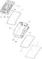
- Figure 2 is an exploded view of a fuel cell with a novel box provided in the first embodiment of the present invention
- Figure 3 is a perspective view of a fuel cell tank according to an embodiment of the invention.
- Figure 4 is a cross-sectional view of the box in the first embodiment of the present invention.
- Fig. 5 is an enlarged view of part A of Fig. 4;
- Figure 6 is an enlarged view of B in Figure 4.
- Figure 7 is an exploded view of the box in the first embodiment of the present invention.
- Figure 8 is a perspective view of the cover plate of the first embodiment of the present invention.
- Figure 9 is an exploded view of the cover plate of the first embodiment of the present invention.
- Embodiment 1 of the present invention is a schematic diagram of the principle of Embodiment 1 of the present invention.
- FIG. 11 is a circuit block diagram of a fuel cell leakage gas detection and control circuit according to an embodiment of the invention.
- Figure 12 is an exploded view of the fuel cell of the second embodiment of the invention.
- FIG. 13 is a schematic diagram of the structure of the bottom plate of the fuel cell in the second embodiment of the present invention.
- Figure 14 is a front view of a fuel cell according to a second embodiment of the invention.
- Figure 15 is a cross-sectional view of C-C in Figure 14;
- Figure 16 is a partial enlarged view of part D in Figure 15;
- Figure 17 is a perspective view of a joint of the third embodiment of the present invention from one angle;
- Figure 19 is a perspective view of the fuel cell of the third embodiment of the present invention.
- Figure 21 is a side view of a fuel cell according to the third embodiment of the present invention.
- Figure 22 is a cross-sectional view taken along line E-E of Figure 21;
- Fig. 23 is a partial enlarged view of part F in Fig. 22.
- this embodiment provides a fuel cell with a new type of box, including a box, a fuel cell module 6 is installed in the box, and the fuel cell module 6 includes a stack module 61,
- the hydrogen circulation pump 62, the air gas path system, the cooling system, the fuel cell control system, and the hydrogen gas path system 63 are characterized in that: the box body includes a bottom plate 1, a box frame 3, and a cover plate 5.
- the fuel cell module 6 Installed on the bottom plate 1, the box frame 3 is formed by connecting side plates 31 end to end.
- the bottom of the box frame 3 is provided with a lower opening 32, the top of the box frame 3 is provided with an upper opening 33, and the box frame 3 has a lower opening 32.
- the cover plate 5 is installed on the box frame 3 and closes the upper opening 33.
- a lower sealing ring 2 is provided between the box frame 3 and the bottom plate 1.
- An upper sealing ring 4 is provided between 3 and the cover plate 5.
- the fuel cell module 6 is first installed on the open bottom plate 1 during production and assembly, and then the box frame 3 is placed outside the fuel cell module 6 and connected
- the relevant interface of the battery module 6 is finally assembled by closing the cover 5, which is easy to assemble;
- the cover 5 and the box frame 3 are sealed by the upper sealing ring 4, and the box frame 3 and the bottom plate 1 are sealed by the bottom Ring 2 is sealed to meet the protection requirements of IP67, and the sealing effect is good;
- the bottom plate 1 and the cover plate 5 can be universally used for fuel cells of different powers.
- the producer only needs to replace the box frame 3 of different heights according to the power density of different fuel cells. This improves the versatility of the outer box and reduces production and design costs.
- the box frame 3 described above is provided with a lower flange 321 outward at the lower opening 32, the lower flange 321 is installed on the bottom plate 1, the lower sealing ring 2 is installed between the lower flange 321 and the bottom plate 1, and the box frame 3 has an upper opening
- An upper flange 331 is provided at 33 outwards, the cover plate 5 is installed on the upper flange 331, and the upper sealing ring 4 is installed between the upper flange 331 and the cover plate 5.
- the arrangement of the upper flange 331 and the lower flange 321 facilitates the installation of the box frame 3 and the cover 5.
- the aforementioned bottom plate 1 has a number of installation blocks 11 protruding outside the box frame 3, and hooks 12 are installed on the installation blocks 11.
- the fuel cell can be hoisted up by the hook 12, which facilitates the installation and transportation of the fuel cell.
- the above-mentioned box frame 3 is provided with a stack cooling liquid connection port 373 connected to the fuel cell module 6, a stack air connection port 371, a hydrogen connection port 372, a power connector 374, a data connector 375 and a fan 36.
- the aforementioned box frame 3 and cover plate 5 are made by sheet metal stamping and forming technology.
- the sheet metal manufacturing process is simple, the processing procedures are few, and the quality reliability is high; the box frame 3 and the cover plate 5 made by the sheet metal stamping process can reduce the overall weight of the fuel cell by about 10%, which reduces the weight of the fuel cell and reduces cost.
- the aforementioned bottom plate 1 is made of aluminum alloy material.
- the bottom plate 1 made of aluminum alloy can provide a strong support structure for the fuel cell module 6 while having the advantage of light weight.
- At least one fan 36 is installed in the box frame 3 described above, and the fan 36 and the air outlet cover 51 are located on opposite sides of the box frame 3. It is more conducive to air circulation in the box.
- the above-mentioned box cover 5 is provided with an exhaust hood 51, the bottom plate 1, the box frame 3 and the cover plate 5 enclose a cavity, the exhaust hood 51 is connected to the cavity, and the exhaust fan 9 is installed in the exhaust hood 51.
- the leaked combustible gas can be discharged more effectively.
- the top of the above-mentioned box cover plate 5 protrudes upwardly from the boss 50.
- the boss 50 forms a gas collecting groove 57.
- the combustible gas concentration sensor 8 is located inside the gas collecting groove 57.
- the exhaust hood 56 is attached to the outside of the gas collecting groove 57 and is connected to the The gas collecting tank 57 is connected.
- the gas collecting tank 57 is located at the highest point of the fuel cell, and a large amount of leaked combustible gas is collected in the gas collecting tank 57, which can discharge the leaked combustible gas more efficiently.
- the above-mentioned combustible gas concentration sensor 8 detects the combustible gas concentration electric signal in the gas collecting tank 57 and transmits it to the fuel cell controller for processing.
- the fuel cell controller shuts down and powers off Stack module 61 and close the hydrogen inlet valve.
- the exhaust hood is arranged on the tank cover, so that the exhaust port is arranged at the highest place of the fuel cell.
- the combustible gas is lighter than air. After leakage, the combustible gas will escape upward and approach the tank cover, which can be more effective The leaked combustible gas can be discharged in time and effectively to improve safety and reliability.
- the above-mentioned box cover 5 includes a cover plate 51, a left side plate 52, a front baffle 53, and a rear baffle 54 are arranged from one side of the cover plate 51, and the left side plate 52, the front baffle 53 and the rear baffle 54 enclose the collection chamber. 56.
- the collecting cavity 56 is located below the air collecting groove 57, the top of the left side plate 52 is provided with an air outlet 521, the air outlet 521 is connected with the air collecting groove 57, and the air exhaust hood 51 is installed at the position of the air outlet 521.
- the structure is simple and easy to manufacture.
- the combustible gas concentration sensor 23 is located in the gas collecting tank 242, which is convenient for accurately detecting the concentration of the leaked combustible gas. It has better safety and reliability, simple structure, convenient installation and easy implementation.
- the above-mentioned exhaust hood 51 is installed at the position of the exhaust port 521 of the left side plate 52 by screws 58 and a sealing ring 59.
- the structure is simple and the sealing is good.
- the aforementioned front baffle 53 and rear baffle 54 have an inclined bottom edge 55 for easy installation.
- this embodiment is an improvement on the basis of the first embodiment and includes a box body.
- the cavity 101 in the box body is equipped with a stack module 61 and a hydrogen circulation pump 62.
- the box body includes a bottom plate. 1.
- the stack module 61 and the hydrogen circulation pump 62 are installed on the bottom plate 1.
- the bottom plate 1 is provided with a leakage hole 121a.
- the leakage hole 121a communicates with the cavity 101 in the box and the outside of the box.
- the leakage hole 121a is close to The outer end of the tank is sealed with a seal 4a. By disassembling the seal 4a, the internal leakage of the fuel cell tank can be detected and drained.
- the structure is simple, and it can effectively prevent the accumulation of liquid in the tank from causing fuel cell failure. run.
- the leakage hole 121a is a bent through hole. One end of the leakage hole 121a is located on the top surface 122a of the bottom plate 1, and the other end of the leakage hole 121a is located on the side surface 123a of the bottom plate 1.
- the seal 4a blocks the leakage hole from the side surface 123a of the bottom plate 1.
- One end of 121a facilitates the discharge of liquid inside the box, and the bent through hole has a certain length to facilitate storage of certain leakage.
- the liquid leakage hole 121a is a right-angle through hole, which facilitates the discharge of liquid inside the box.
- leakage holes 121a which are arranged along the edge of the bottom plate 1 of the box body to facilitate the discharge of liquid inside the box body.
- the sealing member 4a is a sealing plug screw.
- the end of the leakage hole 121a located on the side surface 123a is provided with an internal thread.
- the sealing plug screw is screwed to the end located on the leakage hole 121a near the side surface 123a, which is convenient and quick to install and remove. It is convenient for the staff to regularly check the leakage and discharge.
- a sealing ring 5a is provided between the sealing member 4a and the side surface 123a of the bottom plate 1 to prevent liquid from seeping out.
- the number of the leakage holes 121a is 4, and the leakage holes 121a are located on the two side surfaces 123a of the bottom plate 1, so as to facilitate the discharge of the liquid inside the box.
- a fuel cell includes a box, a stack module 61, and a fuel cell controller.
- the stack module 61 and the fuel cell controller The cooling fluid connector 373 is installed in the cavity 101 of the box body, and the cooling fluid connector 373 is installed on the box body. It is characterized in that: the cooling fluid connector 373 includes a connector body 1b with a through hole 11b in the middle of the connector body 1b. From left to right, it is divided into inner joint 12b, threaded connection section 13b, wrench screw boss 14b and outer joint 15b. It has simple structure, few parts, low manufacturing cost, high sealing reliability, small space occupation and easy installation.
- the above-mentioned threaded connection section 13b is a cone. External threads are machined on the surface of the cone.
- the outer diameter of the part close to the inner joint 12b is smaller, and the outer diameter of the screw boss 14b close to the wrench is larger, which is convenient for installation and has good sealing performance.
- the outer diameter D1 of the above-mentioned wrench screwing boss 14b is larger than the outer diameter D2 of the threaded connecting section 13b, and the outer diameter D2 of the threaded connecting section 13b is larger than the outer diameter D3 of the inner joint 12b, which is convenient for installation.
- the outer diameter D3 of the aforementioned inner joint 12b is equal to the outer diameter D4 of the outer joint 15b.
- the above-mentioned spanner screwing boss 14b has a hexagonal cross-section, which is convenient to cooperate with the spanner and is easy to install.
- the aforementioned joint body 1b is made of hardware materials.
- the above-mentioned stack module 61 is connected to the inner joint 12b through a pipe 103b.
- the boss 14b and the outer joint 15b are screwed by a wrench to protrude outside the box.
- the pipe 103b is a silicone tube, which is convenient for connection and sealing with the inner joint 12b. Simple structure, few parts, low manufacturing cost, high sealing reliability, small space occupation and easy installation.
- the outer joint 15b is used to connect with the pipe of the coolant system outside the box.
- the above-mentioned box body includes a box frame 3 and a cover plate 5 installed on the top of the box frame 3.
- a boss 25b is provided on the side wall of the box frame 3, and a mounting hole 251b is provided on the boss 25b.
- the cavity 101 is connected, and the middle of the joint body 1b is installed in the mounting hole 251b.
- the above-mentioned mounting hole 251b is a tapered hole.
- the inner surface of the tapered hole has internal threads.
- the part of the tapered hole near the cavity 101 has a smaller outer diameter, and the outer diameter near the outside of the box body is larger.
- the threaded connection section 13b and the boss 25b are threadedly connected, the structure is simple, the parts are few, and the manufacturing cost is low.
- threaded connection section 13b is wound with tape 16b on the outside and then screwed into the mounting hole 251b or threaded section 13b is wound with tape 16b on the outside and screwed into the mounting hole 251b after being coated with sealing glue, which can further improve sealing reliability.
- the threaded connection section 13b When installing, the threaded connection section 13b is wrapped with tape 16b and coated with sealing glue. Use a wrench to tighten the wrench to screw the boss 14b, and then turn the wrench to drive the joint body 1b to rotate, so that the threaded connection section 13b and the boss 25b are threadedly connected , Easy installation, few parts, low manufacturing cost, high sealing reliability, and small space occupation.
Landscapes
- Life Sciences & Earth Sciences (AREA)
- Engineering & Computer Science (AREA)
- Manufacturing & Machinery (AREA)
- Sustainable Development (AREA)
- Sustainable Energy (AREA)
- Chemical & Material Sciences (AREA)
- Chemical Kinetics & Catalysis (AREA)
- Electrochemistry (AREA)
- General Chemical & Material Sciences (AREA)
- Fuel Cell (AREA)
Abstract
L'invention concerne une pile à combustible dotée d'un nouveau corps de boîte, comprenant un corps de boîte dans lequel sont installés un module de pile galvanique (61) et un dispositif de commande de pile à combustible. Le corps de boîte comprend une plaque inférieure (1), un cadre de boîte (3) et une plaque de recouvrement (5). Le module de pile galvanique (61) est installé sur la plaque inférieure (1). Le cadre de boîte (3) est formé de plusieurs plaques latérales reliées bout à bout (31), le bas du cadre de boîte (3) comporte une ouverture inférieure (32), le haut du cadre de boîte (3) comporte une ouverture supérieure (33), et l'ouverture inférieure (32) du cadre de boîte (3) est installée sur la plaque inférieure (1). Le cadre de boîte (3) entoure la périphérie du module de pile galvanique (61). La plaque de recouvrement (5) est installée sur le cadre de boîte (3) et ferme l'ouverture supérieure (33). Une bague d'étanchéité inférieure (2) est disposée entre le cadre de boîte (3) et la plaque inférieure (1), et une bague d'étanchéité supérieure (4) est disposée entre le cadre de boîte (3) et la plaque de recouvrement (5). La pile à combustible est pratique à assembler et présente un coût faible ; le corps de boîte dispose d'une bonne universalité.
Applications Claiming Priority (14)
| Application Number | Priority Date | Filing Date | Title |
|---|---|---|---|
| CN201920255007.6U CN209312926U (zh) | 2019-02-28 | 2019-02-28 | 一种带新型箱体的燃料电池 |
| CN201910151098.3 | 2019-02-28 | ||
| CN201920255032.4U CN209418674U (zh) | 2019-02-28 | 2019-02-28 | 一种使用新型安装箱的燃料电池 |
| CN201910151033.9A CN109830733B (zh) | 2019-02-28 | 2019-02-28 | 一种带新型箱体的燃料电池 |
| CN201920255006.1U CN209312925U (zh) | 2019-02-28 | 2019-02-28 | 一种带漏液防护的燃料电池 |
| CN201920255006.1 | 2019-02-28 | ||
| CN201910151033.9 | 2019-02-28 | ||
| CN201920255664.0 | 2019-02-28 | ||
| CN201920255032.4 | 2019-02-28 | ||
| CN201910151760.5A CN109707925B (zh) | 2019-02-28 | 2019-02-28 | 一种用于管道连接的接头及燃料电池 |
| CN201920255664.0U CN209688288U (zh) | 2019-02-28 | 2019-02-28 | 一种用于管道连接的接头及燃料电池 |
| CN201910151760.5 | 2019-02-28 | ||
| CN201910151098.3A CN109728334A (zh) | 2019-02-28 | 2019-02-28 | 一种使用新型安装箱的燃料电池 |
| CN201920255007.6 | 2019-02-28 |
Publications (1)
| Publication Number | Publication Date |
|---|---|
| WO2020173077A1 true WO2020173077A1 (fr) | 2020-09-03 |
Family
ID=72238954
Family Applications (1)
| Application Number | Title | Priority Date | Filing Date |
|---|---|---|---|
| PCT/CN2019/105377 Ceased WO2020173077A1 (fr) | 2019-02-28 | 2019-09-11 | Pile à combustible dotée d'un nouveau corps de boîte |
Country Status (1)
| Country | Link |
|---|---|
| WO (1) | WO2020173077A1 (fr) |
Citations (8)
| Publication number | Priority date | Publication date | Assignee | Title |
|---|---|---|---|---|
| US20030235727A1 (en) * | 2002-06-24 | 2003-12-25 | Noetzel John G. | Solid-oxide fuel cell assembly having an electronic control unit within a structural enclosure |
| CN1866582A (zh) * | 2005-05-20 | 2006-11-22 | 上海神力科技有限公司 | 一种燃料电池电堆的封装装置 |
| CN106935892A (zh) * | 2015-12-10 | 2017-07-07 | 本田技研工业株式会社 | 燃料电池系统 |
| CN109707925A (zh) * | 2019-02-28 | 2019-05-03 | 中山大洋电机股份有限公司 | 一种用于管道连接的接头及燃料电池 |
| CN109728334A (zh) * | 2019-02-28 | 2019-05-07 | 中山大洋电机股份有限公司 | 一种使用新型安装箱的燃料电池 |
| CN109830733A (zh) * | 2019-02-28 | 2019-05-31 | 中山大洋电机股份有限公司 | 一种带新型箱体的燃料电池 |
| CN209312926U (zh) * | 2019-02-28 | 2019-08-27 | 中山大洋电机股份有限公司 | 一种带新型箱体的燃料电池 |
| CN209312925U (zh) * | 2019-02-28 | 2019-08-27 | 中山大洋电机股份有限公司 | 一种带漏液防护的燃料电池 |
-
2019
- 2019-09-11 WO PCT/CN2019/105377 patent/WO2020173077A1/fr not_active Ceased
Patent Citations (8)
| Publication number | Priority date | Publication date | Assignee | Title |
|---|---|---|---|---|
| US20030235727A1 (en) * | 2002-06-24 | 2003-12-25 | Noetzel John G. | Solid-oxide fuel cell assembly having an electronic control unit within a structural enclosure |
| CN1866582A (zh) * | 2005-05-20 | 2006-11-22 | 上海神力科技有限公司 | 一种燃料电池电堆的封装装置 |
| CN106935892A (zh) * | 2015-12-10 | 2017-07-07 | 本田技研工业株式会社 | 燃料电池系统 |
| CN109707925A (zh) * | 2019-02-28 | 2019-05-03 | 中山大洋电机股份有限公司 | 一种用于管道连接的接头及燃料电池 |
| CN109728334A (zh) * | 2019-02-28 | 2019-05-07 | 中山大洋电机股份有限公司 | 一种使用新型安装箱的燃料电池 |
| CN109830733A (zh) * | 2019-02-28 | 2019-05-31 | 中山大洋电机股份有限公司 | 一种带新型箱体的燃料电池 |
| CN209312926U (zh) * | 2019-02-28 | 2019-08-27 | 中山大洋电机股份有限公司 | 一种带新型箱体的燃料电池 |
| CN209312925U (zh) * | 2019-02-28 | 2019-08-27 | 中山大洋电机股份有限公司 | 一种带漏液防护的燃料电池 |
Similar Documents
| Publication | Publication Date | Title |
|---|---|---|
| US20100206721A1 (en) | On demand hydrogen enhancement system for internal and external combustion engine | |
| CN110187278B (zh) | 一种电池模组实验箱装置 | |
| WO2022116908A1 (fr) | Batterie au lithium à haute énergie et système de stockage d'énergie de grande taille la comprenant | |
| CN213071216U (zh) | 一种新能源汽车用电池散热装置 | |
| CN206602729U (zh) | 纯电动物流车用的电机控制器箱体 | |
| CN106793698B (zh) | 风力发电机组密闭式冷却系统 | |
| CN210802824U (zh) | 一种板式换热器漏液报警装置 | |
| CN109707925B (zh) | 一种用于管道连接的接头及燃料电池 | |
| CN209561549U (zh) | 一种燃料电池电堆壳体结构 | |
| WO2020173077A1 (fr) | Pile à combustible dotée d'un nouveau corps de boîte | |
| CN209045713U (zh) | 一种带有热管理系统的新能源汽车动力电池模组 | |
| WO2023036248A1 (fr) | Réservoir de batterie pour système de stockage d'énergie à grande échelle, et procédé de ventilation par explosion | |
| CN109548382B (zh) | 一种高效散热的油田专用变频控制柜 | |
| CN204067518U (zh) | 带有散热装置的电池模块 | |
| CN114614180A (zh) | 一种用于大型储能系统的电池罐 | |
| CN210737698U (zh) | 一种立式隔膜气压罐 | |
| CN104696266A (zh) | 一种液态金属池式驱动装置密封组件 | |
| CN209843764U (zh) | 承压电池结构 | |
| CN215489993U (zh) | 一种具有防腐功能的铸铁散热器 | |
| CN219219216U (zh) | 一种柜式一体化供水设备 | |
| CN218123548U (zh) | 一种被动式电芯灭火系统 | |
| CN217062254U (zh) | 一种锂电池储能柜自动防护系统 | |
| CN118281405A (zh) | 一种水下储能装置 | |
| CN202585678U (zh) | 一种具有散热功能的动力电池及其散热装置 | |
| CN213711244U (zh) | 一种水冷系统用自动补水稳压装置 |
Legal Events
| Date | Code | Title | Description |
|---|---|---|---|
| 121 | Ep: the epo has been informed by wipo that ep was designated in this application |
Ref document number: 19916827 Country of ref document: EP Kind code of ref document: A1 |
|
| NENP | Non-entry into the national phase |
Ref country code: DE |
|
| 122 | Ep: pct application non-entry in european phase |
Ref document number: 19916827 Country of ref document: EP Kind code of ref document: A1 |