WO2020174522A1 - Structure d'électrode intermédiaire, transformateur l'utilisant et détecteur de décharge partielle - Google Patents
Structure d'électrode intermédiaire, transformateur l'utilisant et détecteur de décharge partielle Download PDFInfo
- Publication number
- WO2020174522A1 WO2020174522A1 PCT/JP2019/006999 JP2019006999W WO2020174522A1 WO 2020174522 A1 WO2020174522 A1 WO 2020174522A1 JP 2019006999 W JP2019006999 W JP 2019006999W WO 2020174522 A1 WO2020174522 A1 WO 2020174522A1
- Authority
- WO
- WIPO (PCT)
- Prior art keywords
- transmission line
- voltage
- intermediate electrode
- electrode structure
- conductive member
- Prior art date
- Legal status (The legal status is an assumption and is not a legal conclusion. Google has not performed a legal analysis and makes no representation as to the accuracy of the status listed.)
- Ceased
Links
Images




Classifications
-
- H—ELECTRICITY
- H01—ELECTRIC ELEMENTS
- H01F—MAGNETS; INDUCTANCES; TRANSFORMERS; SELECTION OF MATERIALS FOR THEIR MAGNETIC PROPERTIES
- H01F38/00—Adaptations of transformers or inductances for specific applications or functions
- H01F38/20—Instruments transformers
- H01F38/22—Instruments transformers for single phase AC
- H01F38/24—Voltage transformers
Definitions
- the present invention relates to a transformer for measuring voltage and current in a transmission line or power equipment, and more particularly, to an intermediate electrode structure used in a transmission line and a power device for transmitting high-voltage power, and using the same.
- the present invention relates to a transformer and a partial discharge detection device.
- Patent Document 1 discloses, with reference to FIG. 10, a voltage transformer for a gas insulated switchgear which enhances reliability of a voltage transformer used for a gas insulated switchgear for ultrahigh voltage and facilitates maintenance. Has been done.
- This voltage transformer is arranged in a pipe forming a part of the outer shell container of the gas insulated switchgear with the central axis line shared with the metal tubular containers 902 and 904, and the flanges are attached to the tubular containers 902 and 904.
- a combined metal-made partial pressure electrode container 903 having a cylindrical shape is provided. SF 6 gas is sealed at a predetermined pressure inside the pipe and inside other containers and the like connected to the pipe.
- a main circuit conductor 905 extending linearly along the central axis of the pipeline is housed in the pipeline.
- a cylindrical voltage dividing electrode 916 surrounding the main circuit conductor 905 is arranged in the voltage dividing electrode container 903, and the voltage dividing electrode 916 is electrically connected to the upper end of the connection conductor 915.
- a flange provided on the upper end of the metal connection conduit 906 is connected to the lower flange of the voltage dividing electrode container 903 via an insulating spacer 907.
- the stray capacitance (electrostatic capacity) between the main circuit conductor 905 and the voltage dividing electrode 916 is C 11
- the stray capacitance between the voltage dividing electrode 916 and the voltage dividing electrode container 903 is C 12
- the connecting conductor 915 is indicated by C13.
- this partial voltage potential is used as the primary voltage, and the voltage after conversion by the transformer (transformer) is measured.
- Patent Document 2 discloses a voltage detection device for a three-phase batch type gas insulated switchgear.
- the size of the floating electrode is a high voltage conductor (bus bar). Is formed with a diameter equal to or less than the diameter of.
- the intermediate electrode is made small, the signal level that can be detected is small, and there is a problem that it is difficult to handle.
- a dedicated device for detecting the partial discharge that occurs is provided (see Patent Document 3 above), but it is preferable that the partial discharge can be detected using the same configuration as the transformer. ..
- the present invention provides a small-sized intermediate electrode structure which has a simple structure and is easy to manufacture without forming an intermediate electrode structure inside the container, a transformer using the same, and a partial discharge detection device. To aim.
- An intermediate electrode structure includes a tubular conductive member surrounding a power transmission line, and an insulating member arranged at each of two open ends of the conductive member.
- the conductive member is attached to the conduit that houses the power transmission line through the insulating member, and is used as an intermediate electrode when measuring the voltage of the power transmission line by using the stray capacitance between the power transmission line and the conductive member. To be done.
- the container is formed by the conductive member and the insulating member and the conductive member is used as the intermediate electrode, it is not necessary to form the intermediate electrode inside the container, and the insulation inside the container becomes easy.
- the container can prevent the outer shape of the container from becoming large, and is easier to manufacture than a container having a conventional intermediate electrode.
- the conductive member is made of a non-magnetic metal. Accordingly, the Rogowski coil can be arranged around the intermediate electrode structure to configure the current transformer, and the current of the transmission line can be detected.
- a transformer detects the voltage of a conductive member when AC power is supplied by the above intermediate electrode structure, a capacitor that grounds the conductive member, and a transmission line.
- the detector includes a detector, and the detector detects the voltage of the conductive line as a voltage divided by the stray capacitance and the capacitor.
- a voltage transformer can be formed using the above intermediate electrode structure.
- a relatively large stray capacitance can be realized, so that the detection signal level becomes large and the detection signal can be handled easily.
- the transformer further includes an isolation amplifier that amplifies the voltage signal detected by the detection unit. This makes it possible to easily insulate the measuring equipment from the high-voltage electrical equipment including the power transmission line that is the measurement target, and protect the measuring device.
- the transformer further includes a transformer that converts the magnitude of the voltage signal detected by the detection unit, and an operational amplifier that amplifies the output voltage signal of the transformer. This makes it possible to easily insulate the measuring equipment from the high-voltage electrical equipment including the power transmission line that is the measurement target, and protect the measuring device.
- a transformer according to a third aspect of the present invention is configured such that the intermediate electrode structure described above, a conductive ground wire that grounds a conductive member, and a current flowing through the ground wire when AC power is supplied by the power transmission line. It includes a detection unit that detects a current and an integration unit that integrates the signal detected by the detection unit, and the integration result of the integration unit is used to generate a measured value of the voltage of the transmission line.
- a voltage transformer can be formed using the above intermediate electrode structure.
- a relatively large stray capacitance can be realized, so that the detection signal level becomes large and the detection signal can be handled easily.
- the detection unit is a coil having a core formed of a member having a relative magnetic permeability of 1000 or more.
- the current flowing through the ground line can be detected more accurately. Since the core having a high relative permeability has a small exciting current, it is suitable for sensing a small current.
- the integration unit includes an operational amplifier and a capacitor that electrically connects the output terminal and the inverting input terminal of the operational amplifier.
- the current signal detected by the detector can be integrated and output as a voltage signal.
- the conductive member is grounded via a bidirectional diode. As a result, an excessive current can be released to the ground and safety can be secured.
- a transformer according to a fourth aspect of the present invention is configured such that the intermediate electrode structure described above, a conductive ground wire that grounds a conductive member, and a current flowing through the ground wire when AC power is supplied by the power transmission line.
- a detection unit that detects a current
- a first integration unit that integrates the signal detected by the detection unit
- a Rogowski coil that is arranged on a plane perpendicular to the axis of the intermediate electrode structure, and AC power is transmitted by a transmission line.
- a second integrator that integrates the voltage generated across the Rogowski coil when supplied, the conductive member being formed of a non-magnetic member, and the result of the integration by the first integrator being transmitted.
- a partial discharge detection device is the intermediate electrode structure described above, a conductive ground wire for grounding a conductive member, a detector for detecting a current flowing through the ground wire, and a detector. And a determination unit that determines whether or not partial discharge has occurred by performing a predetermined process on the signal detected by. Thereby, a partial discharge detection device can be formed using the above intermediate electrode structure.
- the intermediate electrode is configured by the outer shell (conductive member) of the container, it is not necessary to form the intermediate electrode structure inside the container, and the insulation inside the container is facilitated. Further, it is possible to prevent the outer shape of the container from becoming large. Further, since a relatively large capacitor capacity (stray capacity) can be realized, the detection signal level becomes large and the handling becomes easy.
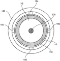
- FIG. 8 is a sectional view showing a section taken along the line VIII-VIII in FIG. 7.
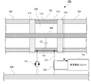
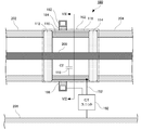
- a transformer 100 according to the first embodiment of the present invention includes an intermediate electrode structure 102 arranged between exterior pipes 202 and 204 that accommodate a power transmission line 200, a voltage dividing capacitor 104, and a voltage dividing capacitor 104. , Signal matching unit 106 and protective element 108.
- the power transmission line 200 is arranged on the central axes of the outer pipes 202 and 204.
- the intermediate electrode structure 102 includes an outer shell portion 110, spacers 112 and 114 arranged at open ends on both sides of the outer shell portion 110, and an insulating coating 116 covering the outer periphery of the outer shell portion 110.
- the outer shell 110 is insulated from the ground 208, and is also electrically insulated from the exterior tubes 202 and 204.
- the outer shell 110 is formed in a tubular shape so as to surround the power transmission line 200 with a metal member.
- the outer shell 110 may be a cylinder (having a circular cross section perpendicular to the axis) or a polygonal tube (having a polygonal cross section perpendicular to the axis).
- the outer shell 110 is preferably formed of a metal having high conductivity (for example, iron, copper, aluminum, alloys thereof, stainless steel, or the like).
- the spacers 112 and 114 are for supporting the power transmission line 200 and fixing the intermediate electrode structure 102 to the exterior tubes 202 and 204.
- the spacers 112 and 114 are formed of a non-conductive member (resin or the like).
- the spacers 112 and 114 are preferably formed so as to penetrate the power transmission line 200 and allow the power transmission line 200 to be arranged on the axis of the outer shell 110.
- a sealed space 206 is formed inside the intermediate electrode structure 102 by the outer shell 110 and the spacers 112 and 114.
- the space 206 (the space sealed by the outer shell 110 and the spacers 112 and 114) may be filled with oil, gas, a molding member, or the like for insulation.
- the voltage dividing capacitor 104 has one end connected to the outer shell 110 and the other end connected (grounded) to the ground 208.
- the end of the voltage dividing capacitor 104 connected to the outer shell 110 is also connected to the signal matching unit 106.
- the method for electrically connecting the voltage dividing capacitor 104 to the outer shell 110 is arbitrary. It may be welded or fixed with screws, bolts or the like.
- Protective element 108 is for releasing a current to ground 208 when an abnormal voltage occurs, and is also called a lightning arrester.
- the protection element 108 is provided for safety, is not essential for realizing the function of the transformer 100, and may not be provided.
- the insulating coating 116 is also for ensuring the safety of workers around and is not essential for realizing the function of the transformer 100.
- the electric power (voltage) transmitted by the power transmission line 200 is an AC voltage having a predetermined frequency (for example, 50 Hz, 60 Hz, etc.), and the surrounding metal is electromagnetically affected according to the fluctuation.
- a stray capacitance 118 exists between the power transmission line 200 and the outer shell 110.
- the outer shell 110, the voltage dividing capacitor 104, and the stray capacitance 118 form a voltage dividing circuit that divides the voltage of the power transmission line 200.
- the voltage of the power transmission line 200 due to the capacitance C2 of the stray capacitance 118 between the power transmission line 200 and the outer shell 110 and the capacitance C1 of the voltage dividing capacitor 104.
- a voltage obtained by dividing V0 is generated.
- the voltage V1 at the connection node of the voltage dividing capacitor 104 and the signal matching unit 106 depends on the capacitances C1 and C2, but is a relatively high voltage if the voltage of the transmission line 200 is a high voltage.
- the capacitance C2 of the stray capacitance 118 generated between the power transmission line 200 and the outer shell part 110 considering whether or not the space inside the intermediate electrode structure 102 is filled with gas or the like, the power transmission line 200 and the outer shell are considered.
- a desired capacity can be obtained by adjusting the distance from the portion 110 (radius in the case of the cylindrical outer shell portion 110) and the axial length of the outer shell portion 110.
- the capacitance C2 of the stray capacitance 118 is preferably about 100 to 1000 pF. When the capacitance C2 of the stray capacitance 118 is small, the detection signal is small.
- the detection signal is as small as about 10 ⁇ A.
- the leak current from other circuits it is not easy to maintain the accuracy (for example, even if the leak current is 1 ⁇ A, the error is about 10%).
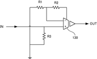
- the signal matching unit 106 includes an isolation amplifier 130 and resistors R1 to R3.
- the input signal IN (voltage V1) to the signal matching unit 106 is amplified by the isolation amplifier 130 and output as an output signal OUT to a measuring device (not shown) in the subsequent stage.
- the output signal OUT can be sampled at a predetermined frequency, converted into digital data, and the voltage V0 of the power transmission line 200 can be obtained using the above formula.
- the measurement result can be stored and the fluctuation can be observed.
- the isolation amplifier 130 is also called an isolation amplifier, and the input side and the output side are insulated. Therefore, it is possible to insulate the high-voltage power equipment including the power transmission line 200 from the measuring device that processes the output signal of the isolation amplifier 130.
- the isolation amplifier 130 for example, an optical coupling type amplifier using an optical element or a transformer coupling type amplifier using a transformer can be used.
- the connection relationship between the isolation amplifier 130 and the surrounding resistors is not limited to that shown in FIG. It is sufficient that it can output the output signal OUT obtained by amplifying the input signal IN. It may be an inverting amplifier circuit in which the polarities of the input signal IN and the output signal OUT are inverted, or a non-inverting amplifier circuit having the same polarity.
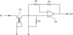
- the signal matching unit 106 may include a transformer 132, an operational amplifier 134, and resistors R4 to R6, as shown in FIG.
- the input signal IN (voltage V1) to the primary side coil of the transformer 132 is adjusted in voltage level by the transformer 132, is output as a voltage of a predetermined level from the secondary side coil, and is input to the operational amplifier 134. ..
- the signal input to the operational amplifier 134 is amplified by the operational amplifier 134, output to the measuring device in the subsequent stage, and processed in the same manner as above.
- the transformer 132 insulates the transmission line 200 side from the measuring device in the subsequent stage of the operational amplifier 134. Therefore, the operational amplifier 134 is not an isolation amplifier but an ordinary operational amplifier (Operational Amplifier). Good.
- connection relationship between the operational amplifier 134 and the surrounding resistors is not limited to that shown in FIG. It is sufficient that it can output the output signal OUT obtained by amplifying the input signal IN. It may be a non-inverting amplifier circuit or an inverting amplifier circuit.
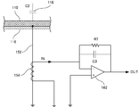
- the transformer 150 according to the present modification is wound around the intermediate electrode structure 102, the ground wire 152 disposed between the intermediate electrode structure 102 and the ground 208, and the ground wire 152.
- the intermediate electrode structure 102 is configured similarly to the above embodiment. Therefore, repeated description will not be repeated, and here, the points different from the above-described embodiment will be mainly described.
- the ground wire 152 is formed of a conductive member in a linear shape (rod shape), one end of which is connected to the outer shell portion 110 of the intermediate electrode structure 102, and the other end of which is connected to the ground 208.
- the method for electrically connecting the ground wire 152 to the outer shell 110 is arbitrary. It may be welded or fixed with screws, bolts or the like.
- the detection coil 154 is for detecting a current flowing through the ground wire 152.
- the stray capacitance 118 (C2) exists between the power transmission line 200 and the outer shell 110, the voltage applied to the power transmission line 200 causes a fluctuation current via the C2 to the ground line 152. Flowing. A secondary current is generated at the output of the detection coil 154 by the fluctuating magnetic field formed by the fluctuating current flowing through the ground wire 152. Therefore, this is detected by the signal matching unit 156, the detection signal is integrated, and the voltage of the power transmission line 200 is measured (calculated).
- the detection coil 154 Since the current detected by the detection coil 154 is relatively small, it is preferable to provide the detection coil 154 with a core formed of a member having a high magnetic permeability (for example, a member having a relative magnetic permeability of 1000 or more, such as permalloy).
- a member having a high magnetic permeability for example, a member having a relative magnetic permeability of 1000 or more, such as permalloy.
- the voltage generated in the outer shell 110 is usually extremely small. However, if an abnormal discharge occurs inside or the like, an overvoltage may occur, and the transformer (semiconductor element or the like inside the signal matching unit 156) may be destroyed. Therefore, a method of protecting by using a diode having a small forward voltage can be considered by utilizing that the voltage generated in the outer shell 110 is small.
- This method is relatively inexpensive and can cover large currents. That is, the diode pair 158 including two diodes (hereinafter also referred to as bidirectional diodes) connected so that the forward directions are opposite to each other is provided.
- the diode pair 158 is provided for safety and is for releasing the current to the ground when an excessive current is generated.
- the number of diodes is not limited to two (one pair) and may be four (two pairs) or more.
- the signal matching unit 156 includes an operational amplifier 162, a resistor R7, and a capacitor C3.
- FIG. 5 shows a part of the configuration of the intermediate electrode structure 102 shown in FIG.
- the inverting input terminal (terminal marked with “ ⁇ ”) of the operational amplifier 162 is connected to one end of the detection coil 154, and the non-inverting input terminal (terminal marked with “+”) of the operational amplifier 162 is grounded. ..
- the output terminal and the inverting input terminal of the operational amplifier 162 are connected by the capacitor C3 and the resistor R7 which are connected in parallel.
- the operational amplifier 162 functions as an integrator, and the output signal OUT becomes a signal obtained by integrating the input signal IN input to the inverting input terminal.
- This configuration can maximize the capability (especially the frequency characteristic) as the current detection sensor including the core and the detection coil described above. The reason is that this configuration has an advantage that the burden resistance (load resistance) can be minimized equivalently for the detection coil.
- the resistor R7 is for stabilizing the circuit and is not essential for integration.
- the detection coil 154 detects is a current flowing through the ground wire 152.
- the operational amplifier 162 is insulated from the electric power equipment including the transmission line by the detection coil 154, it may be a normal operational amplifier, not an isolation amplifier.
- an analog detection signal may be converted into digital data and then integrated by a semiconductor operator (DSP (Digital Signal Processor) or the like).
- DSP Digital Signal Processor
- a partial discharge detection device 170 has the same configuration as that of FIG. 4 and is arranged between intermediate electrode structure 102 and intermediate electrode structure 102 and ground 208. And a ground wire 152, a detection coil 172 wound around the ground wire 152, a signal matching unit 156 to which a signal (current) generated in the detection coil 172 is input, and a diode pair 158.
- the detection coil 172 is a coil capable of detecting a high frequency current (MHz order) generated by partial discharge. The method of detecting the partial discharge is the same as that of Patent Document 3 described above.
- Patent Document 3 when a partial discharge occurs in an electric equipment arranged between the bus bar and the ground, a capacitor (hereinafter, referred to as a compensation capacitor) for compensating for the charge lost by the partial discharge is provided between the bus bar and the ground. Provide in between.
- the electric charge accumulated in the compensation capacitor is supplied to the partial discharge generation unit (charge disappearance source) via the bus bar. At this time, the occurrence of partial discharge can be detected by detecting the flowing current.
- the stray capacitance 118 generated between the power transmission line 200 and the outer shell 110 is made to function as a compensation capacitor.
- a current flows through the ground line 152 by the supply of AC power from the power transmission line 200.
- the partial discharge occurs, as shown in FIG. 6, the charge accumulated in the stray capacitance 118 is supplied to the partial discharge portion via the power transmission line 200, and a large compensation current 174 instantaneously flows.
- the detection signal from the detection coil 172 also instantaneously increases. Therefore, the partial discharge can be detected by observing the change in the detection signal of the detection coil 172.
- partial discharge can be detected by performing a predetermined process (peak detection or the like) on the signal detected by the detection coil 172. Further, the influence of the commercial current may be separated from the detection signal by using the phase of the commercial current flowing through the power transmission line 200, and the current generated by the partial discharge may be detected.
- a predetermined process peak detection or the like
- the signal matching unit 156 of FIG. 6 is a circuit that processes the high frequency signal detected by the detection coil 172.
- the partial discharge detection device 170 shown in FIG. 6 can be applied to, for example, a gas-insulated switchgear to detect partial discharge.
- the transformer of the second embodiment includes a Rogowski coil in addition to the configuration shown in the first embodiment.
- the transformer 180 according to the second embodiment includes the intermediate electrode structure 102, the Rogowski coil 182, the intermediate electrode structure 102 and the ground 208. And a CT unit 192 provided on the ground line 152.
- the intermediate electrode structure 102 is configured similarly to the first embodiment (see FIGS. 1 and 4). Therefore, repeated description will not be repeated, and here, the points different from the above-described embodiment will be mainly described.
- the Rogowski coil 182 is fixed around the intermediate electrode structure 102 via holding members 184 to 190.
- the Rogowski coil (also referred to as a toroidal coil) is a coil having an outer appearance in which a coated conductive wire is wound around a core (or an air core) of an annular body (in FIG. 7, around a ring having a bus bar as a central axis). ..
- the Rogowski coil 182 is preferably molded with resin or the like. This is detected by the Rogowski coil with a signal obtained by differentiating the magnetic flux generated by the current flowing through the power transmission line 200 (the magnetic flux that is formed in a plane perpendicular to the busbar and is along a concentric circle centered on the busbar position).
- the outer shell 110 is made of a conductive non-magnetic material (for example, copper, aluminum, and alloys thereof, and non-magnetic stainless steel) so that the outer shell 110 does not disturb the magnetic field. Needs to be done.
- Both ends of the transformer 180 are connected to the CT unit 192, and the signal detected by the transformer 180 is integrated by the CT unit 192, as described later.
- the holding members 184 to 190 are for fixing the Rogowski coil 182 at a predetermined distance from the intermediate electrode structure 102, and are made of a non-conductive member such as resin.
- the number, shape, and arrangement of the holding members 184 to 190 are arbitrary, and it is sufficient that the Rogowski coil 182 can be fixed at a predetermined distance from the intermediate electrode structure 102.
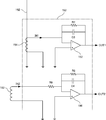
- the CT unit 192 includes a circuit including a detection coil 154, an operational amplifier 162, a resistor R7, and a capacitor C3 (hereinafter referred to as a first circuit), a Rogowski coil 182, an operational amplifier 196, resistors R8, and R9. , And a circuit including the capacitor C4 (hereinafter, referred to as a second circuit).
- the first circuit is the same as that in FIG. 5, and therefore the duplicated description will not be repeated.
- the first circuit outputs a voltage (output signal OUT1) obtained by integrating the current (input signal IN1) flowing through the detection coil 154 when the current flows through the ground line 152.
- the output signal OUT1 is output to the measuring device in the subsequent stage and processed in the same manner as above.
- the second circuit is called a Miller integrating circuit, the operational amplifier 196 functions as an integrator, and the output signal OUT2 is a signal obtained by integrating the input signal IN2 input to the inverting input terminal.
- the second circuit integrates the voltage generated across the Rogowski coil 182, so that the output signal OUT2 has a value proportional to the bus current (current of the power transmission line 200). That is, due to the inductance L of the Rogowski coil 182, the voltage V(t) across the Rogowski coil 182 is V(t) ⁇ L ⁇ dI(, where I(t) is the current of the bus (transmission line 200). t)/dt (where t represents time and dI(t)/dt represents the derivative of the current). Therefore, the current I(t) can be obtained by integrating the voltage V(t).
- the transformer 180 functions as a voltage transformer by the first circuit, and functions as a current transformer by the Rogowski coil 182 and the second circuit.
- the present invention it is possible to provide a small-sized intermediate electrode structure which has a simple structure and is easy to manufacture without forming an intermediate electrode structure inside the container, a transformer and a partial discharge detection device using the same.
Landscapes
- Engineering & Computer Science (AREA)
- Power Engineering (AREA)
- Measuring Instrument Details And Bridges, And Automatic Balancing Devices (AREA)
Abstract
L'invention concerne une structure d'électrode intermédiaire comprenant un élément conducteur cylindrique entourant la périphérie d'une ligne de transmission de puissance et un élément isolant disposé au niveau de chacune de deux extrémités ouvertes de l'élément conducteur, l'élément conducteur étant ajusté par l'intermédiaire de l'élément isolant à un conduit qui reçoit la ligne de transmission de puissance et utilisé comme électrode intermédiaire lors de la mesure de la tension de la ligne de transmission de puissance à l'aide d'une capacité parasite entre la ligne de transmission de puissance et l'élément conducteur. Ainsi, la structure d'électrode intermédiaire élimine le besoin de former une électrode intermédiaire à l'intérieur d'un récipient, permettant de supprimer une augmentation de la forme extérieure du récipient, et est plus facile à fabriquer qu'un récipient classique qui a l'électrode intermédiaire intégrée.
Priority Applications (1)
| Application Number | Priority Date | Filing Date | Title |
|---|---|---|---|
| PCT/JP2019/006999 WO2020174522A1 (fr) | 2019-02-25 | 2019-02-25 | Structure d'électrode intermédiaire, transformateur l'utilisant et détecteur de décharge partielle |
Applications Claiming Priority (1)
| Application Number | Priority Date | Filing Date | Title |
|---|---|---|---|
| PCT/JP2019/006999 WO2020174522A1 (fr) | 2019-02-25 | 2019-02-25 | Structure d'électrode intermédiaire, transformateur l'utilisant et détecteur de décharge partielle |
Publications (1)
| Publication Number | Publication Date |
|---|---|
| WO2020174522A1 true WO2020174522A1 (fr) | 2020-09-03 |
Family
ID=72239215
Family Applications (1)
| Application Number | Title | Priority Date | Filing Date |
|---|---|---|---|
| PCT/JP2019/006999 Ceased WO2020174522A1 (fr) | 2019-02-25 | 2019-02-25 | Structure d'électrode intermédiaire, transformateur l'utilisant et détecteur de décharge partielle |
Country Status (1)
| Country | Link |
|---|---|
| WO (1) | WO2020174522A1 (fr) |
Cited By (2)
| Publication number | Priority date | Publication date | Assignee | Title |
|---|---|---|---|---|
| WO2022069332A1 (fr) * | 2020-09-30 | 2022-04-07 | Siemens Energy Global GmbH & Co. KG | Appareil haute tension sous enveloppe et transformateur de courant pour l'appareil haute tension sous enveloppe |
| CN116247799A (zh) * | 2022-12-30 | 2023-06-09 | 国网宁夏电力有限公司电力科学研究院 | 一种高压限流装置操作机构及测控单元的供电系统 |
Citations (5)
| Publication number | Priority date | Publication date | Assignee | Title |
|---|---|---|---|---|
| JPS5074423U (fr) * | 1973-11-10 | 1975-06-30 | ||
| JPH0382108A (ja) * | 1989-08-25 | 1991-04-08 | Mitsubishi Electric Corp | 光計器用変圧器 |
| JPH06109800A (ja) * | 1992-09-30 | 1994-04-22 | Takaoka Electric Mfg Co Ltd | 部分放電監視方法 |
| JP2012233738A (ja) * | 2011-04-28 | 2012-11-29 | Mitsubishi Electric Corp | 計器用変成器 |
| JP2015175689A (ja) * | 2014-03-14 | 2015-10-05 | 日新電機株式会社 | 部分放電監視装置および部分放電監視システム |
-
2019
- 2019-02-25 WO PCT/JP2019/006999 patent/WO2020174522A1/fr not_active Ceased
Patent Citations (5)
| Publication number | Priority date | Publication date | Assignee | Title |
|---|---|---|---|---|
| JPS5074423U (fr) * | 1973-11-10 | 1975-06-30 | ||
| JPH0382108A (ja) * | 1989-08-25 | 1991-04-08 | Mitsubishi Electric Corp | 光計器用変圧器 |
| JPH06109800A (ja) * | 1992-09-30 | 1994-04-22 | Takaoka Electric Mfg Co Ltd | 部分放電監視方法 |
| JP2012233738A (ja) * | 2011-04-28 | 2012-11-29 | Mitsubishi Electric Corp | 計器用変成器 |
| JP2015175689A (ja) * | 2014-03-14 | 2015-10-05 | 日新電機株式会社 | 部分放電監視装置および部分放電監視システム |
Cited By (2)
| Publication number | Priority date | Publication date | Assignee | Title |
|---|---|---|---|---|
| WO2022069332A1 (fr) * | 2020-09-30 | 2022-04-07 | Siemens Energy Global GmbH & Co. KG | Appareil haute tension sous enveloppe et transformateur de courant pour l'appareil haute tension sous enveloppe |
| CN116247799A (zh) * | 2022-12-30 | 2023-06-09 | 国网宁夏电力有限公司电力科学研究院 | 一种高压限流装置操作机构及测控单元的供电系统 |
Similar Documents
| Publication | Publication Date | Title |
|---|---|---|
| US5432438A (en) | Combined current and voltage transformer for a metal-enclosed gas-insulated high-voltage switching station | |
| JP6050309B2 (ja) | 高電圧測定システム | |
| US6850399B1 (en) | Gas insulated device and failure rating method | |
| US5272460A (en) | Current and voltage transformer for a metal-encapsulated, gas-insulated high-voltage installation | |
| HU180695B (en) | Combined converter of current and voltage for metal-clad gas-insulated high-voltage apparatuses | |
| US7027280B2 (en) | Gas insulating apparatus and method for locating fault point thereof | |
| WO2020174522A1 (fr) | Structure d'électrode intermédiaire, transformateur l'utilisant et détecteur de décharge partielle | |
| CN103682862B (zh) | 一种环网柜电缆插接件 | |
| US3829742A (en) | Voltage transformer for a fully insulated metal-clad,high-voltage switching installation | |
| JP2004117310A (ja) | 複合形変成器とそれを含む電気測定システム | |
| KR20210044462A (ko) | 전류측정장치 및 이를 포함하는 가스절연개폐장치 | |
| AG | Low power voltage and current transducers for protecting and measuring medium and high voltage systems | |
| JP7127730B2 (ja) | 電圧変成器 | |
| JPH07244111A (ja) | 漏れ電流検出センサ | |
| CN214473845U (zh) | 一种在线监测的sf6电流互感器 | |
| JP2020134430A (ja) | 中間電極構造体及びそれを用いた変成器 | |
| CN202013855U (zh) | 内置低压侧电子电流互感器的断路器 | |
| KR102781410B1 (ko) | 센서 일체형 에폭시 부싱 | |
| WO2012160625A1 (fr) | Transformateur pour instruments | |
| KR102872860B1 (ko) | 전자식 전압 센서 | |
| JPS59110303A (ja) | 密閉電気機器の短絡事故検出装置 | |
| Mercure | Development of a novel measuring device: the dynamic current transducer | |
| JP2000187045A (ja) | 電圧変成器 | |
| CN102034649A (zh) | 一种内置低压侧电子电流互感器的断路器 | |
| CN111009402A (zh) | 一种双级多变比标准电压互感器 |
Legal Events
| Date | Code | Title | Description |
|---|---|---|---|
| 121 | Ep: the epo has been informed by wipo that ep was designated in this application |
Ref document number: 19916900 Country of ref document: EP Kind code of ref document: A1 |
|
| NENP | Non-entry into the national phase |
Ref country code: DE |
|
| 122 | Ep: pct application non-entry in european phase |
Ref document number: 19916900 Country of ref document: EP Kind code of ref document: A1 |
|
| NENP | Non-entry into the national phase |
Ref country code: JP |