WO2020174525A1 - 析出強化型鋳造合品の溶接補修方法 - Google Patents
析出強化型鋳造合品の溶接補修方法 Download PDFInfo
- Publication number
- WO2020174525A1 WO2020174525A1 PCT/JP2019/007013 JP2019007013W WO2020174525A1 WO 2020174525 A1 WO2020174525 A1 WO 2020174525A1 JP 2019007013 W JP2019007013 W JP 2019007013W WO 2020174525 A1 WO2020174525 A1 WO 2020174525A1
- Authority
- WO
- WIPO (PCT)
- Prior art keywords
- welding
- precipitation
- strengthened
- repair method
- repair
- Prior art date
- Legal status (The legal status is an assumption and is not a legal conclusion. Google has not performed a legal analysis and makes no representation as to the accuracy of the status listed.)
- Ceased
Links
Images



Classifications
-
- B—PERFORMING OPERATIONS; TRANSPORTING
- B23—MACHINE TOOLS; METAL-WORKING NOT OTHERWISE PROVIDED FOR
- B23K—SOLDERING OR UNSOLDERING; WELDING; CLADDING OR PLATING BY SOLDERING OR WELDING; CUTTING BY APPLYING HEAT LOCALLY, e.g. FLAME CUTTING; WORKING BY LASER BEAM
- B23K26/00—Working by laser beam, e.g. welding, cutting or boring
- B23K26/0006—Working by laser beam, e.g. welding, cutting or boring taking account of the properties of the material involved
-
- B—PERFORMING OPERATIONS; TRANSPORTING
- B23—MACHINE TOOLS; METAL-WORKING NOT OTHERWISE PROVIDED FOR
- B23K—SOLDERING OR UNSOLDERING; WELDING; CLADDING OR PLATING BY SOLDERING OR WELDING; CUTTING BY APPLYING HEAT LOCALLY, e.g. FLAME CUTTING; WORKING BY LASER BEAM
- B23K26/00—Working by laser beam, e.g. welding, cutting or boring
- B23K26/34—Laser welding for purposes other than joining
-
- B—PERFORMING OPERATIONS; TRANSPORTING
- B23—MACHINE TOOLS; METAL-WORKING NOT OTHERWISE PROVIDED FOR
- B23K—SOLDERING OR UNSOLDERING; WELDING; CLADDING OR PLATING BY SOLDERING OR WELDING; CUTTING BY APPLYING HEAT LOCALLY, e.g. FLAME CUTTING; WORKING BY LASER BEAM
- B23K26/00—Working by laser beam, e.g. welding, cutting or boring
- B23K26/34—Laser welding for purposes other than joining
- B23K26/342—Build-up welding
-
- B—PERFORMING OPERATIONS; TRANSPORTING
- B23—MACHINE TOOLS; METAL-WORKING NOT OTHERWISE PROVIDED FOR
- B23K—SOLDERING OR UNSOLDERING; WELDING; CLADDING OR PLATING BY SOLDERING OR WELDING; CUTTING BY APPLYING HEAT LOCALLY, e.g. FLAME CUTTING; WORKING BY LASER BEAM
- B23K9/00—Arc welding or cutting
- B23K9/04—Welding for other purposes than joining, e.g. built-up welding
- B23K9/044—Built-up welding on three-dimensional surfaces
-
- B—PERFORMING OPERATIONS; TRANSPORTING
- B23—MACHINE TOOLS; METAL-WORKING NOT OTHERWISE PROVIDED FOR
- B23K—SOLDERING OR UNSOLDERING; WELDING; CLADDING OR PLATING BY SOLDERING OR WELDING; CUTTING BY APPLYING HEAT LOCALLY, e.g. FLAME CUTTING; WORKING BY LASER BEAM
- B23K9/00—Arc welding or cutting
- B23K9/16—Arc welding or cutting making use of shielding gas
- B23K9/167—Arc welding or cutting making use of shielding gas and of a non-consumable electrode
-
- B—PERFORMING OPERATIONS; TRANSPORTING
- B23—MACHINE TOOLS; METAL-WORKING NOT OTHERWISE PROVIDED FOR
- B23K—SOLDERING OR UNSOLDERING; WELDING; CLADDING OR PLATING BY SOLDERING OR WELDING; CUTTING BY APPLYING HEAT LOCALLY, e.g. FLAME CUTTING; WORKING BY LASER BEAM
- B23K9/00—Arc welding or cutting
- B23K9/16—Arc welding or cutting making use of shielding gas
- B23K9/173—Arc welding or cutting making use of shielding gas and of a consumable electrode
-
- C—CHEMISTRY; METALLURGY
- C22—METALLURGY; FERROUS OR NON-FERROUS ALLOYS; TREATMENT OF ALLOYS OR NON-FERROUS METALS
- C22C—ALLOYS
- C22C19/00—Alloys based on nickel or cobalt
- C22C19/03—Alloys based on nickel or cobalt based on nickel
-
- B—PERFORMING OPERATIONS; TRANSPORTING
- B23—MACHINE TOOLS; METAL-WORKING NOT OTHERWISE PROVIDED FOR
- B23K—SOLDERING OR UNSOLDERING; WELDING; CLADDING OR PLATING BY SOLDERING OR WELDING; CUTTING BY APPLYING HEAT LOCALLY, e.g. FLAME CUTTING; WORKING BY LASER BEAM
- B23K2101/00—Articles made by soldering, welding or cutting
- B23K2101/001—Turbines
-
- B—PERFORMING OPERATIONS; TRANSPORTING
- B23—MACHINE TOOLS; METAL-WORKING NOT OTHERWISE PROVIDED FOR
- B23K—SOLDERING OR UNSOLDERING; WELDING; CLADDING OR PLATING BY SOLDERING OR WELDING; CUTTING BY APPLYING HEAT LOCALLY, e.g. FLAME CUTTING; WORKING BY LASER BEAM
- B23K2103/00—Materials to be soldered, welded or cut
- B23K2103/18—Dissimilar materials
- B23K2103/26—Alloys of Nickel and Cobalt and Chromium
Definitions
- the present invention relates to a welding repair method for a precipitation strengthened cast composite product.
- Patent Document 1 Al: more than 5 at% and 13 at%, V: 9.5% or more and less than 17.4 at%, Nb: 0 at% or more and 5 at% or less, B: 50 ppm by weight or more and 1000 wt%
- Patent Document 2 Al is used as a main component and Al is 2 to 9 atom %, V is 10 to 17 atom %, (Ta and/or W) is 0.5 to 8 atom %, and Nb is 0 to In a Ni-based intermetallic compound alloy containing B: 10 to 1000 ppm by weight based on the total weight of a composition of 100 at% including 6 at %, Co: 0 to 6 at %, Cr: 0 to 6 at %. It is disclosed that the structure has a dual dual phase structure consisting of proeutectoid L1 2 phase and (L1 2 +D0 22 ) eutectoid structure.
- Patent Document 3 regarding repair of a gas turbine blade with a squealer made of a nickel-based superalloy, after removing a damaged portion of the squealer by cutting and removing, a welded portion from the nickel-based superalloy is formed on the portion. Is formed by welding, and the build-up portion has a temperature of not less than 1/2 of the melting point (m° C.) of the nickel-base superalloy forming the build-up portion and not less than 15° C./min in the temperature range not higher than the melting point. It is described that heating is performed at a temperature rising rate of 500° C./minute or less, cooling gas is blown to the overlay portion to rapidly cool it, and then solution treatment is performed on the overlay portion.
- m° C. melting point
- Patent Document 3 the welding work represented by Patent Document 3 is currently extremely complicated and inefficient. For example, when heat-treating a cast product after welding, it is necessary to transport the parts to a factory, which is time-consuming and costly because the parts are large. Further, in the same document, it is assumed that laser welding is performed for welding, but in such welding, cracks often occur again, and the yield is not good.
- the present invention has been made in view of such a current situation, and an object thereof is to provide a welding repair method for a precipitation-strengthened casting product capable of reliably and efficiently repairing a precipitation-strengthened casting product. To do.
- One of the present invention for achieving the above-mentioned object is a method for repairing a damaged portion of a precipitation-strengthened cast alloy product, which contains a solid solution strengthened alloy, and A weld material having high toughness is used, and the damaged portion is welded by micro TIG welding.
- the present inventor uses a welding material having higher toughness than a precipitation-strengthened cast alloy, which is a base material, containing a solid solution-strengthened alloy, when the base material is a precipitation-strengthened cast alloy, at the time of repair. Also, even if thermal stress is applied to the welded part after repair, it can be buffered (released to the outside), so the durability of the base material against thermal stress can be significantly increased, and the conventional heat treatment is unnecessary.
- the present inventor performs the welding in this case by micro TIG welding, thereby keeping the temperature gradient in the vicinity of the welded portion at the time of repair relatively small, and generating the thermal stress in the welded portion and the base metal resulting therefrom.
- the welding current in the micro TIG welding is set to 50 A or less.
- the welding current of the micro TIG welding As described above, by setting the welding current of the micro TIG welding to 50 A or less, it is possible to reliably prevent damage to the repaired portion and its surroundings during and after the repair (for example, re-generation of cracks or cracks in the repaired portion). it can.
- the welding material is a nickel-based alloy containing a dual phase nanostructured intermetallic compound alloy.
- the welding material contains a nickel-based alloy
- nickel has high toughness (ductility), so damage during repair and after repair (for example, cracks or cracks at the repair site) Reoccurrence)
- the effect of prevention can be surely obtained.
- the dual-phase nanostructure it is possible to obtain the effect of being resistant to high temperatures and maintaining good wear resistance and corrosion resistance.
- the welding material is introduced into the damaged portion so as to cover the exposed surface of the damaged portion.
- a recess is formed on the surface of the cast composite product by cutting a part of the cast composite product so as to include the damaged portion.
- the micro TIG welding is performed on the recess.
- FIG. 1 is a diagram showing an example of components of a gas turbine provided in a thermal power plant or the like.
- FIG. 2 is a diagram showing an example of a procedure of a welding repair method for a cast composite product according to the present embodiment.
- FIG. 3 is a diagram showing an example of the groove forming step.
- FIG. 4 is a diagram illustrating an example of the welding process.
- FIG. 5 is a figure which shows the result of the repair welding test which the present inventors implemented.
- FIG. 1 is a diagram showing an example of components of a gas turbine provided in a thermal power plant or the like.
- the gas turbine 10 is composed of, for example, a plurality of nickel-cobalt heat-resistant alloys.
- the gas turbine 10 includes a combustor sub-chamber 22 and a combustor main chamber 24, a combustor 20 that mixes fuel with compressed air and combusts it, and combustion gas and steam generated in the combustor 20.
- each of these components is assumed to be a precipitation-strengthened casting compound product in which the metal material is mainly precipitation-strengthened by aging heat treatment or the like.
- FIG. 2 is a diagram showing an example of a procedure of a welding repair method for a cast composite product according to the present embodiment.
- a groove forming step of forming a recess (groove) by cutting a portion including a generated crack is performed (s11).
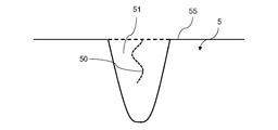
- FIG. 3 is a diagram showing an example of the groove forming step. As shown in the figure, by using a drill, an end mill, or the like on the surface 55 of the component 5 of the gas turbine in which the crack 50 has occurred, the recess 51 ( Groove) is formed. As a result, the entire crack 50 is removed.
- the recess 51 is, for example, a space having a V-shaped or U-shaped cross section.
- FIG. 4 is a diagram illustrating an example of a welding process.
- the welding process by using the welding rod 57 and the welding torch 54 containing the welding material 53, the exposed surface 52 is surely provided on the exposed surface 52 where the inside of the base material (component 5) is exposed due to the formation of the recess 51. Welding is performed so as to cover the entire surface (s11).
- the material of the welding rod 57 used for welding is an alloy containing a solid solution strengthened metal and having a higher toughness than the component 5, which is the base material.
- An example of such an alloy is a nickel-based alloy.
- this welding material 53 is a nickel-based alloy containing a dual phase nanostructured intermetallic compound alloy. That is, by adding aluminum and vanadium to nickel at a predetermined ratio and casting and solidifying the nickel-based nickel-based alloy, a eutectoid structure having a D0 22 phase (Ni 3 Al) and an L1 2 phase (Ni 3 V) is formed at a nano level. It is an alloy.
- the addition ratios of aluminum and vanadium and the addition ratios of other trace elements (boron etc.) are not particularly limited.
- the welding method in the welding process is performed as follows, for example. First, regarding the amount of heat input to the recess 51 (the amount of heat energy supplied by the welding torch 54 per unit time), heat is input to the recess 51 with a welding current of a magnitude that is used in ordinary micro TIG welding. Then, a large thermal stress is generated in the concave portion 51, and as a result, the component 5 as the base material may be cracked. Therefore, the welding current needs to be set lower than that. For example, the welding current is preferably 50 A or less.
- the moving speed (welding speed) of the welding torch 54 if the moving speed is too fast, a temperature difference between the heat input part and its surroundings (a temperature difference due to thermal diffusion) is likely to occur, so that the base metal It causes a crack of a certain component 5. Therefore, it is important that the moving speed of the welding torch 54 is not too fast. As a result, the necessary heat can be uniformly supplied to the recess 51.
- a welded portion having substantially the same shape corresponding to the recessed portion 51 is formed, and a crack generated in the component 5 is repaired.
- the inventors of the present invention conducted a welding repair test of a cast joint product using the above welding method. That is, in the present test, a combustor of a gas turbine having a damaged portion (the material is Hastelloy (registered trademark) X) was used as a test base metal, and micro TIG welding with a high-concentration nickel welding rod (welding current was maintained at 50 A or less). ) was performed to repair the damaged part by welding.
- a combustor of a gas turbine having a damaged portion the material is Hastelloy (registered trademark) X
- micro TIG welding with a high-concentration nickel welding rod welding current was maintained at 50 A or less
- the state of the test base material without damage hereinafter simply referred to as the base material
- the base material after the weld repair hereinafter referred to as the repaired member
- FIG. 5 is a diagram showing a result of a welding repair test conducted by the present inventors.
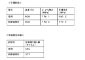
- the 0.2% proof stress of the base material was 178.1 MPa, whereas the 0.2% proof stress of the repaired member was 170.3 MPa.
- the tensile strength of the base material was 187.2 MPa, whereas the tensile strength of the repaired member was 177.7 MPa. That is, regarding the tensile strength, the repaired member had a strength almost equal to that of the base material.
- the number of repeated fractures of the base metal was 555 cycles, whereas that of the repaired member (to the welded portion).
- the number of repeated breaks was 377 cycles. That is, regarding the durability against high temperature fatigue, the repaired member has a durability of about 70% of the base material, and it was found that it can sufficiently withstand the operation of the actual machine.
- a welding material having a higher toughness than the precipitation-strengthened cast alloy product which is a base material, containing a solid solution strengthened alloy.
- the base material is a precipitation-strengthened cast composite product, it is possible to buffer (releas to the outside) the thermal stress even when heat stress is applied to the weld during repair and after repair.
- the durability against thermal stress can be significantly increased, and the heat treatment that has been conventionally performed is not necessary.
- the temperature gradient in the vicinity of the weld during repair is kept relatively small, and the occurrence of thermal stress in the weld and the resulting reduction in strength of the base metal are suppressed. I thought about what I could do.
- the casting material can be repaired reliably and efficiently by appropriately combining the welding material and the welding method.
- the welding current of the micro TIG welding is set to 50 A or less, so that the repaired portion at the time of and after repairing and the damage around it (for example, cracking of the repaired portion or (Regeneration of cracks) can be reliably prevented.
- the welding material is a nickel-based alloy containing a dual phase nanostructure intermetallic compound alloy, since nickel has high toughness (ductility), After the repair, the effect of preventing damage to the repaired part and its surroundings (for example, cracking of the repaired part and re-generation of cracks) can be reliably obtained.
- the dual-phase nanostructure it is possible to obtain the effect of being resistant to high temperatures and maintaining good wear resistance and corrosion resistance.
- the welding repair method of the cast composite product of the present embodiment by performing welding so as to cover the exposed surface of the damaged part of the cast composite product, at the time of repairing and after repairing, the damaged part of the base metal and the welded part It is possible to prevent a situation where local deformation or damage occurs at the boundary and re-repair of the base material is required.
- a portion including a damaged portion is cut to form a recess (groove), and thus the damaged portion is removed. Since micro TIG welding can be performed with, it is possible to prevent damage to the repaired part and its surroundings (for example, re-generation of cracks and cracks in the repaired part) during and after repairing due to damage that occurred in the base metal. You can
- the groove is formed before performing the micro TIG welding, but without forming the groove, the overlay welding is directly performed on the damaged portion of the cast joint product. Good. Further, for damages other than cracks, such as wear (reduction in thickness) of the cast joint product, overlay welding may be directly performed on the damaged portion of the cast joint product. Further, the welding repair method according to the present embodiment is applied to general welding repair of heat-resistant alloy members such as the components of the gas turbine 10 (combustor 20, transition piece 30, stationary blades 42, moving blades 44). Can be applied.
Landscapes
- Engineering & Computer Science (AREA)
- Physics & Mathematics (AREA)
- Mechanical Engineering (AREA)
- Plasma & Fusion (AREA)
- Optics & Photonics (AREA)
- Chemical & Material Sciences (AREA)
- Materials Engineering (AREA)
- Metallurgy (AREA)
- Organic Chemistry (AREA)
- Arc Welding In General (AREA)
Abstract
析出強化型鋳造合品の損傷部を補修する方法であって、固溶強化型の合金を含む、前記析出強化型鋳造合品よりも靱性が高い溶接材料53を用い、マイクロティグ溶接により前記損傷部を溶接する。
Description
本発明は、析出強化型鋳造合品の溶接補修方法に関する。
火力発電設備や原子力発電設備等におけるタービンの動翼、燃焼器、尾筒等の鋳造品は、その素材に析出強化型の超耐熱合金(ニッケル基超耐熱合金等)を用いることで、高温強度を向上させることができる。しかしながら、これらの鋳造品も長期間にわたって高温・高圧条件下におかれると、タービンの起動及び停止の繰り返し等により発生する熱応力が原因となって、表面等に亀裂や損傷が生じることがある。この場合、発電所ではTIG溶接やレーザー溶接等で補修を行うことで対応している。
この点、母材の素材を改良することで、補修の効果を上げることが考えられる。例えば、特許文献1には、Al:5at%より大で13at%、V:9.5%以上で17.4at%より小、Nb:0at%以上5at%以下、B:50重量ppm以上1000重量ppm以下、残部は不純物を除きNiからなり、初相L12相と(L12+D022)共析組織との2重複相組織を有するNi3Al基金属間化合物が記載されている。また、特許文献2には、Niを主成分とし且つAl:2~9原子%,V:10~17原子%,(Ta及び/又はW):0.5~8原子%,Nb:0~6原子%,Co:0~6原子%,Cr:0~6原子%を含む合計100原子%の組成の合計重量に対してB:10~1000重量ppmを含むNi基金属間化合物合金において、初析L12相と(L12+D022)共析組織とからなる2重複相組織を有するものが開示されている。
他方、補修方法としては、特許文献3には、ニッケル基超合金からなるスキーラ付きガスタービン動翼の補修に関して、スキーラの損傷部を切削除去した後、当該部分にニッケル基超合金から肉盛部を溶接によって形成し、肉盛部を、この肉盛部を構成するニッケル基超合金の融点(m℃)の1/2以上の温度であって、融点以下の温度範囲に15℃/分以上500℃/分以下の昇温速度で加熱し、肉盛部に冷却ガスを吹き付け急冷し、その後、肉盛部に対して溶体化処理を行うことが記載されている。
ところが、特許文献3に代表されるような溶接作業は、非常に煩雑で未だ効率が悪いのが現状である。例えば、鋳造品の溶接後の熱処理に際して、部品を工場に運搬して行うことが必要となるが、大型の部品であることから時間もコストもかかる。また、同文献では溶接にレーザー溶接を行うことが想定されているが、そのような溶接では亀裂が再発生することが多く、歩留まりが良くない。
本発明はこのような現状に鑑みてなされたものであり、その目的は、析出強化型鋳造合品を確実かつ効率的に補修することが可能な析出強化型鋳造合品の溶接補修方法を提供することにある。
前述の目的を達成するための本発明の一つは、析出強化型鋳造合品の損傷部を補修する方法であって、固溶強化型の合金を含む、前記析出強化型鋳造合品よりも靱性が高い溶接材料を用い、マイクロティグ溶接により前記損傷部を溶接する。
本発明者は、固溶強化型の合金を含む、母材たる析出強化型鋳造合品よりも靱性が高い溶接材料を、母材が析出強化型鋳造合品の場合に用いることで、補修時及び補修後の溶接部に熱応力がかかってもこれを緩衝させる(外部に逃がす)ことができるため、母材の熱応力に対する耐久性を有意に高めることができ、従来行っていた熱処理も不要となるという知見を得た。さらに本発明者は、この場合の溶接をマイクロティグ溶接で行うことにより、補修時の溶接部の近傍における温度勾配を比較的小さく保ち、溶接部の熱応力の発生及びこれに起因する母材の強度低下を抑制することができることに想到した。このように、本発明の溶接補修方法によれば、溶接材料及び溶接方法を適切に組み合わせることで、析出強化型鋳造合品を確実かつ効率よく補修することができる。
なお、本発明においては、例えば、前記マイクロティグ溶接における溶接電流を50A以下とする。
このように、マイクロティグ溶接の溶接電流を50A以下とすることで、補修時及び補修後の補修部位及びその周囲の損傷(例えば、補修部位の割れや亀裂の再発生)を確実に防ぐことができる。
なお、本発明においては、例えば、前記溶接材料は二重複相ナノ組織金属間化合物合金を含むニッケル基合金である。
このように、まず溶接材料がニッケル基合金を含むことで、ニッケルは靱性(延性)が高いため、補修時及び補修後において、補修部位及びその周囲の損傷(例えば、補修部位の割れや亀裂の再発生)防ぐ効果が確実に得られる。また、二重複相ナノ組織を有することで、高温に強く、耐摩耗性、耐食性を良好に保つ効果も得られる。
なお、本発明においては、例えば、前記マイクロティグ溶接においては、前記損傷部の露出面を覆うように前記溶接材料を前記損傷部に導入する。
このように、鋳造合品の損傷部の露出面を覆うように溶接を行うことで、補修時及び補修後において、母材の損傷部と溶接の境界において局所的な変形や損傷が発生して母材の再補修が必要となるような事態を防ぐことができる。
なお、本発明においては、例えば、前記マイクロティグ溶接を行う前に、前記損傷部を含むようにして前記鋳造合品の一部を切削することにより前記鋳造合品の表面に凹部を形成し、形成した凹部に対して前記マイクロティグ溶接を行う。
このように、マイクロティグ溶接を行う前に、損傷部を含む部分を切削して凹部(開先)を形成することで、損傷部分が除去された状態でマイクロティグ溶接を行うことができるので、母材で発生した損傷に起因する、補修時及び補修後の補修部位及びその周囲の損傷(例えば、補修部位の割れや亀裂の再発生)を防ぐことができる。
本発明によれば、析出強化型鋳造合品を確実かつ効率的に補修することができる。
本発明の実施の形態について、図面を参照しつつ説明する。
まず、図1は、火力発電所等に設けられるガスタービンの構成部品の一例を示した図である。ガスタービン10は、例えば、複数の、ニッケル-コバルト系の耐熱合金で構成される。具体的には、ガスタービン10は、燃焼器副室22及び燃焼器主室24を備え、燃料を圧縮空気と混合して燃焼させる燃焼器20と、燃焼器20で発生した燃焼ガスや水蒸気等が流通する尾筒30(トランジションピース)と、尾筒30から流入した燃焼ガス等の熱エネルギーを回転エネルギーに変換するタービン室40とを備えて構成される。タービン室40には、燃焼ガス等を整流する静翼42と、燃焼ガス等を圧縮し回転エネルギーに変換する動翼44とが、交互に複数配置される。なお、これらの各構成部品は、本実施形態では、金属材料に対して主に時効熱処理等による析出強化を行った析出強化型鋳造合品であるものとする。
まず、図1は、火力発電所等に設けられるガスタービンの構成部品の一例を示した図である。ガスタービン10は、例えば、複数の、ニッケル-コバルト系の耐熱合金で構成される。具体的には、ガスタービン10は、燃焼器副室22及び燃焼器主室24を備え、燃料を圧縮空気と混合して燃焼させる燃焼器20と、燃焼器20で発生した燃焼ガスや水蒸気等が流通する尾筒30(トランジションピース)と、尾筒30から流入した燃焼ガス等の熱エネルギーを回転エネルギーに変換するタービン室40とを備えて構成される。タービン室40には、燃焼ガス等を整流する静翼42と、燃焼ガス等を圧縮し回転エネルギーに変換する動翼44とが、交互に複数配置される。なお、これらの各構成部品は、本実施形態では、金属材料に対して主に時効熱処理等による析出強化を行った析出強化型鋳造合品であるものとする。
このようなガスタービン10の構成部品に対しては、ガスタービン10の起動及び停止の繰り返しに起因した熱応力が発生し、各構成部品の表面付近に亀裂により損傷が発生しやすい。そこで、このような表面に発生した亀裂に対する溶接補修を例に、本実施形態に係る鋳造合品の溶接補修方法を説明する。
図2は、本実施形態に係る、鋳造合品の溶接補修方法の手順の一例を示す図である。
まず、後述するマイクロティグ溶接を行う前に、発生した亀裂を含む部分を切削することにより凹部(開先)を形成する開先形成工程を実施する(s11)。
まず、後述するマイクロティグ溶接を行う前に、発生した亀裂を含む部分を切削することにより凹部(開先)を形成する開先形成工程を実施する(s11)。
図3は、開先形成工程の一例を示す図である。同図に示すように、亀裂50が発生したガスタービンの構成部品5の表面55に対して、ドリルやエンドミル等を用いることで、亀裂50を含むように構成部品5の表面55に凹部51(開先)を形成する。これにより、亀裂50全体を除去する。なお、凹部51は、例えば、その断面形状がV字状又はU字状の空間となるような空間とする。
次に、図2に示すように、開先形成工程で形成した凹部51に対してマイクロティグ(Micro Tungsten Inert Gas)溶接を行うことで、凹部51を充填する溶接工程を実施する(s13)。
ここで、図4は、溶接工程の一例を説明する図である。溶接工程では、溶接材料53を含む溶接棒57及び溶接トーチ54を用いることにより、凹部51の形成により母材(構成部品5)の内部が露出した露出面52上に、露出面52を確実に全面的に覆うように溶接を行う(s11)。
溶接に用いる溶接棒57の素材(溶接材料53)は、固溶強化型の金属を含む、母材である構成部品5よりも靭性が高い合金とする。このような合金としては、例えば、ニッケル基合金がある。
さらに、この溶接材料53は、二重複相ナノ組織金属間化合物合金を含むニッケル基合金である。すなわち、ニッケルにアルミニウム及びバナジウムを所定割合で加えて鋳造凝固することで、ナノレベルで、D022相(Ni3Al)とL12相(Ni3V)を有する共析組織を形成したニッケル基合金である。なお、アルミニウム及びバナジウムの添加割合、また、その他の微量元素(ホウ素等)の添加割合は特に限定されるものではない。
溶接工程における溶接方法は、具体的には、例えば以下のように実施する。まず、凹部51に対する入熱量(溶接トーチ54による、単位時間あたりの熱エネルギー供給量)については、凹部51に、通常のマイクロティグ溶接で使用される程度の大きさの溶接電流で入熱を行うと、凹部51に大きな熱応力が発生し、その結果、母材たる構成部品5に割れが生じるおそれがあるので、溶接電流はそれよりも低めに設定する必要がある。例えば、溶接電流は50A以下とすることが好ましい。
なお、溶接トーチ54の移動速度(溶接速度)については、その移動速度が速すぎると、入熱部とその周囲との温度差(熱拡散に起因する温度差)が生じ易いため、母材である構成部品5の割れの原因となる。そこで、溶接トーチ54の移動速度は速くしすぎないことが重要である。これにより、凹部51に対して満遍なく必要な熱供給を行うことができる。
以上のような溶接方法で溶接を行うことにより、凹部51に対応する略同一形状の溶接部を形成し、構成部品5に生じた亀裂を補修する。
<溶接補修試験>
本発明者らは、以上の溶接方法を用いた、鋳造合品の溶接補修試験を行った。すなわち、本試験では、損傷部を有するガスタービンの燃焼器(材料は、ハステロイ(登録商標)X)を試験母材として、高濃度ニッケル溶接棒によるマイクロティグ溶接(溶接電流は50A以下を維持した)を実施することで、損傷部の溶接補修を行った。この溶接補修後、引張試験及び高温疲労試験を行うことで、損傷の無い状態の試験母材(以下、単に母材という)と溶接補修後の母材(以下、補修後部材という)との状態を比較した。
本発明者らは、以上の溶接方法を用いた、鋳造合品の溶接補修試験を行った。すなわち、本試験では、損傷部を有するガスタービンの燃焼器(材料は、ハステロイ(登録商標)X)を試験母材として、高濃度ニッケル溶接棒によるマイクロティグ溶接(溶接電流は50A以下を維持した)を実施することで、損傷部の溶接補修を行った。この溶接補修後、引張試験及び高温疲労試験を行うことで、損傷の無い状態の試験母材(以下、単に母材という)と溶接補修後の母材(以下、補修後部材という)との状態を比較した。
図5は、本発明者らが実施した溶接補修試験の結果を示す図である。引張試験(900℃大気中)では、母材の0.2%耐力は178.1MPaであったのに対して補修後部材の0.2%耐力は170.3MPaであった。また、母材の引張強さは187.2MPaであったのに対して補修後部材の引張強さは177.7MPaであった。すなわち、引張り強さに関して、補修後部材は母材とほぼ同等の強度を有していた。
また、高温疲労試験(900℃大気中。荷重制御は15~150MPa(応力換算)。)では、母材の破断繰り返し数は555サイクルであったのに対して補修後部材の(溶接部に対する)破断繰り返し数は377サイクルであった。すなわち、高温疲労に対する耐久性に関して、補修後部材は母材の7割程度の耐久性を有しており、実機の運用に充分に耐えることが可能であることがわかった。
以上に説明したように、本実施形態の析出強化型鋳造合品の溶接補修方法によれば、固溶強化型の合金を含む、母材たる析出強化型鋳造合品よりも靱性が高い溶接材料を、母材が析出強化型鋳造合品の場合に用いることで、補修時及び補修後の溶接部に熱応力がかかってもこれを緩衝させる(外部に逃がす)ことができるため、母材の熱応力に対する耐久性を有意に高めることができ、従来行っていた熱処理も不要となる。さらに、この場合の溶接をマイクロティグ溶接で行うことにより、補修時の溶接部の近傍における温度勾配を比較的小さく保ち、溶接部の熱応力の発生及びこれに起因する母材の強度低下を抑制することができることに想到した。このように、本実施形態の溶接補修方法によれば、溶接材料及び溶接方法を適切に組み合わせることで、鋳造合品を確実かつ効率よく補修することができる。
また、本実施形態の鋳造合品の溶接補修方法では、マイクロティグ溶接の溶接電流を50A以下とすることで、補修時及び補修後の補修部位及びその周囲の損傷(例えば、補修部位の割れや亀裂の再発生)を確実に防ぐことができる。
また、本実施形態の鋳造合品の溶接補修方法では、溶接材料は二重複相ナノ組織金属間化合物合金を含むニッケル基合金であることで、ニッケルは靱性(延性)が高いため、補修時及び補修後において、補修部位及びその周囲の損傷(例えば、補修部位の割れや亀裂の再発生)防ぐ効果が確実に得られる。また、二重複相ナノ組織を有することで、高温に強く、耐摩耗性、耐食性を良好に保つ効果も得られる。
また、本実施形態の鋳造合品の溶接補修方法では、鋳造合品の損傷部の露出面を覆うように溶接を行うことで、補修時及び補修後において、母材の損傷部と溶接部の境界において局所的な変形や損傷が発生して母材の再補修が必要となるような事態を防ぐことができる。
また、本実施形態の鋳造合品の溶接補修方法では、マイクロティグ溶接を行う前に、損傷部を含む部分を切削して凹部(開先)を形成することで、損傷部分が除去された状態でマイクロティグ溶接を行うことができるので、母材で発生した損傷に起因する、補修時及び補修後の補修部位及びその周囲の損傷(例えば、補修部位の割れや亀裂の再発生)を防ぐことができる。
以上の実施形態の説明は、本発明の理解を容易にするためのものであり、本発明を限定するものではない。本発明はその趣旨を逸脱することなく、変更、改良され得ると共に本発明にはその等価物が含まれる。
例えば、本実施形態では、亀裂補修において、マイクロティグ溶接を行う前に開先を形成するものとしたが、開先を形成することなく、鋳造合品の損傷部に直接肉盛溶接を行ってもよい。また、亀裂以外の損傷、例えば鋳造合品の摩耗(減肉)等に対しても、鋳造合品の損傷部に直接肉盛溶接を行ってもよい。また、本実施形態に係る溶接補修方法は、ガスタービン10の構成部品(燃焼器20、尾筒30、静翼42、動翼44)をはじめとするな、耐熱合金部材の溶接補修一般に対して適用することができる。
5 構成部品、10 ガスタービン、20 燃焼器、22 燃焼器副室、24 燃焼器主室、30 尾筒、40 タービン室、42 静翼、44 動翼、50 亀裂、51 凹部、52 露出面、53 溶接材料、54 溶接トーチ、55 表面、56 粉末、57 溶接棒
Claims (5)
- 析出強化型鋳造合品の損傷部を補修する方法であって、
固溶強化型の合金を含む、前記析出強化型鋳造合品よりも靱性が高い溶接材料を用い、マイクロティグ溶接により前記損傷部を溶接する、析出強化型鋳造合品の溶接補修方法。 - 前記マイクロティグ溶接における溶接電流を50A以下とする、請求項1に記載の析出強化型鋳造合品の溶接補修方法。
- 前記溶接材料は二重複相ナノ組織金属間化合物合金を含むニッケル基合金である、請求項1に記載の析出強化型鋳造合品の溶接補修方法。
- 前記マイクロティグ溶接においては、前記損傷部の露出面を覆うように前記溶接材料を前記損傷部に導入する、請求項1に記載の析出強化型鋳造合品の溶接補修方法。
- 前記マイクロティグ溶接を行う前に、前記損傷部を含むようにして前記鋳造合品の一部を切削することにより前記析出強化型鋳造合品の表面に凹部を形成し、形成した凹部に対して前記マイクロティグ溶接を行う、請求項1に記載の析出強化型鋳造合品の溶接補修方法。
Priority Applications (4)
| Application Number | Priority Date | Filing Date | Title |
|---|---|---|---|
| JP2019530863A JP6573061B1 (ja) | 2019-02-25 | 2019-02-25 | 析出強化型鋳造合品の溶接補修方法 |
| US17/433,482 US20220134472A1 (en) | 2019-02-25 | 2019-02-25 | Precipitation-strengthened cast product welding repair method |
| PCT/JP2019/007013 WO2020174525A1 (ja) | 2019-02-25 | 2019-02-25 | 析出強化型鋳造合品の溶接補修方法 |
| EP19917438.4A EP3932603A4 (en) | 2019-02-25 | 2019-02-25 | WELDING REPAIR METHOD FOR PRECIPITATION REINFORCED CAST PRODUCT |
Applications Claiming Priority (1)
| Application Number | Priority Date | Filing Date | Title |
|---|---|---|---|
| PCT/JP2019/007013 WO2020174525A1 (ja) | 2019-02-25 | 2019-02-25 | 析出強化型鋳造合品の溶接補修方法 |
Publications (1)
| Publication Number | Publication Date |
|---|---|
| WO2020174525A1 true WO2020174525A1 (ja) | 2020-09-03 |
Family
ID=67909537
Family Applications (1)
| Application Number | Title | Priority Date | Filing Date |
|---|---|---|---|
| PCT/JP2019/007013 Ceased WO2020174525A1 (ja) | 2019-02-25 | 2019-02-25 | 析出強化型鋳造合品の溶接補修方法 |
Country Status (4)
| Country | Link |
|---|---|
| US (1) | US20220134472A1 (ja) |
| EP (1) | EP3932603A4 (ja) |
| JP (1) | JP6573061B1 (ja) |
| WO (1) | WO2020174525A1 (ja) |
Citations (7)
| Publication number | Priority date | Publication date | Assignee | Title |
|---|---|---|---|---|
| WO2007086185A1 (ja) | 2006-01-30 | 2007-08-02 | Osaka Prefecture University Public Corporation | 2重複相組織を有するNi3Al基金属間化合物及びその製造方法,耐熱構造材 |
| JP2008274314A (ja) * | 2007-04-25 | 2008-11-13 | Hitachi Ltd | ガスタービン翼およびその製造方法 |
| JP2009215649A (ja) | 2008-02-15 | 2009-09-24 | Osaka Industrial Promotion Organization | 高い硬度を有するNi基金属間化合物合金 |
| JP2011079054A (ja) * | 2009-09-10 | 2011-04-21 | Sumitomo Chemical Co Ltd | ピットの補修方法および金属部材の補修方法 |
| JP2011136344A (ja) * | 2009-12-25 | 2011-07-14 | Mitsubishi Heavy Ind Ltd | ガスタービン部材の補修方法及びガスタービン部材 |
| JP2013068085A (ja) | 2011-09-20 | 2013-04-18 | Toshiba Corp | スキーラ付きガスタービン動翼の補修方法 |
| JP2017190688A (ja) * | 2016-04-12 | 2017-10-19 | 株式会社東芝 | タービン部材、軸流タービン、およびタービン部材の製造方法 |
Family Cites Families (4)
| Publication number | Priority date | Publication date | Assignee | Title |
|---|---|---|---|---|
| US6364971B1 (en) * | 2000-01-20 | 2002-04-02 | Electric Power Research Institute | Apparatus and method of repairing turbine blades |
| US6996906B2 (en) * | 2002-12-17 | 2006-02-14 | General Electric Company | Method of repairing a turbine blade and blade repaired thereby |
| US8561298B2 (en) * | 2007-03-01 | 2013-10-22 | Siemens Energy, Inc. | Superalloy component welding at ambient temperature |
| US10960497B2 (en) * | 2017-02-01 | 2021-03-30 | Hrl Laboratories, Llc | Nanoparticle composite welding filler materials, and methods for producing the same |
-
2019
- 2019-02-25 US US17/433,482 patent/US20220134472A1/en not_active Abandoned
- 2019-02-25 WO PCT/JP2019/007013 patent/WO2020174525A1/ja not_active Ceased
- 2019-02-25 EP EP19917438.4A patent/EP3932603A4/en not_active Withdrawn
- 2019-02-25 JP JP2019530863A patent/JP6573061B1/ja active Active
Patent Citations (7)
| Publication number | Priority date | Publication date | Assignee | Title |
|---|---|---|---|---|
| WO2007086185A1 (ja) | 2006-01-30 | 2007-08-02 | Osaka Prefecture University Public Corporation | 2重複相組織を有するNi3Al基金属間化合物及びその製造方法,耐熱構造材 |
| JP2008274314A (ja) * | 2007-04-25 | 2008-11-13 | Hitachi Ltd | ガスタービン翼およびその製造方法 |
| JP2009215649A (ja) | 2008-02-15 | 2009-09-24 | Osaka Industrial Promotion Organization | 高い硬度を有するNi基金属間化合物合金 |
| JP2011079054A (ja) * | 2009-09-10 | 2011-04-21 | Sumitomo Chemical Co Ltd | ピットの補修方法および金属部材の補修方法 |
| JP2011136344A (ja) * | 2009-12-25 | 2011-07-14 | Mitsubishi Heavy Ind Ltd | ガスタービン部材の補修方法及びガスタービン部材 |
| JP2013068085A (ja) | 2011-09-20 | 2013-04-18 | Toshiba Corp | スキーラ付きガスタービン動翼の補修方法 |
| JP2017190688A (ja) * | 2016-04-12 | 2017-10-19 | 株式会社東芝 | タービン部材、軸流タービン、およびタービン部材の製造方法 |
Non-Patent Citations (1)
| Title |
|---|
| See also references of EP3932603A4 |
Also Published As
| Publication number | Publication date |
|---|---|
| EP3932603A4 (en) | 2022-05-04 |
| JP6573061B1 (ja) | 2019-09-11 |
| US20220134472A1 (en) | 2022-05-05 |
| JPWO2020174525A1 (ja) | 2021-03-11 |
| EP3932603A1 (en) | 2022-01-05 |
Similar Documents
| Publication | Publication Date | Title |
|---|---|---|
| Henderson et al. | Nickel based superalloy welding practices for industrial gas turbine applications | |
| RU2635688C2 (ru) | Способ ремонта и изготовления компонентов газотурбинного двигателя и компоненты газотурбинного двигателя, отремонтированные или изготовленные с его использованием | |
| JP6086992B2 (ja) | 超合金のクラッディング及び溶融溶接方法 | |
| US7547188B2 (en) | Ni-based alloy member, method of producing the alloy member, turbine engine part, welding material, and method of producing the welding material | |
| EP2815841B1 (en) | Method for post-weld heat treatment of welded components made of gamma prime strengthened superalloys | |
| US11180840B2 (en) | High gamma prime nickel based superalloy, its use, and method of manufacturing of turbine engine components | |
| US11072044B2 (en) | Superalloy component braze repair with isostatic solution treatment | |
| JP5537587B2 (ja) | Ni基合金溶接材料並びにこれを用いた溶接ワイヤ、溶接棒及び溶接用粉末 | |
| US6468367B1 (en) | Superalloy weld composition and repaired turbine engine component | |
| EP1473106A1 (en) | Electron beam welding method providing post-weld heat treatment | |
| JP2011062749A (ja) | タービンエンジン部品を形成する超合金組成物及び方法 | |
| CA3048051A1 (en) | High gamma prime nickel based weldable superalloy and method of repairing and manufacturing of turbine engine components using the same | |
| JP2011064077A (ja) | ガスタービン部品およびその補修方法 | |
| JP6642780B1 (ja) | 析出強化型鋳造合品の溶接補修方法 | |
| JP2022529145A5 (ja) | ||
| US20120251840A1 (en) | Nickel-base weld materials, processes of using, and components formed therewith | |
| JP6573061B1 (ja) | 析出強化型鋳造合品の溶接補修方法 | |
| EP2687312B1 (en) | Method of welding alloy articles | |
| JP5550298B2 (ja) | 蒸気タービンの鍛造部品用のNi基合金、蒸気タービンのタービンロータ、蒸気タービンの動翼、蒸気タービンの静翼、蒸気タービン用螺合部材、および蒸気タービン用配管 | |
| US11913093B2 (en) | High gamma prime nickel based welding material | |
| Arjakine et al. | Advanced weld repair of gas turbine hot section components | |
| Wang | Welding and repair of single crystal Ni-based superalloys | |
| HK1231013B (zh) | 修复和制造涡轮发动机部件的方法及涡轮发动机部件 | |
| Hreben et al. | Similar and Dissimilar Welding of Nickel-Based Superalloys for A-USC Steam Turbine Rotors in NextGenPower Project | |
| HK1231013A1 (en) | Method of repairing and manufacturing of turbine engine components and turbine engine components |
Legal Events
| Date | Code | Title | Description |
|---|---|---|---|
| ENP | Entry into the national phase |
Ref document number: 2019530863 Country of ref document: JP Kind code of ref document: A |
|
| 121 | Ep: the epo has been informed by wipo that ep was designated in this application |
Ref document number: 19917438 Country of ref document: EP Kind code of ref document: A1 |
|
| NENP | Non-entry into the national phase |
Ref country code: DE |
|
| ENP | Entry into the national phase |
Ref document number: 2019917438 Country of ref document: EP Effective date: 20210927 |