WO2020174525A1 - Procédé de réparation par soudage pour produit coulé renforcé par précipitation - Google Patents
Procédé de réparation par soudage pour produit coulé renforcé par précipitation Download PDFInfo
- Publication number
- WO2020174525A1 WO2020174525A1 PCT/JP2019/007013 JP2019007013W WO2020174525A1 WO 2020174525 A1 WO2020174525 A1 WO 2020174525A1 JP 2019007013 W JP2019007013 W JP 2019007013W WO 2020174525 A1 WO2020174525 A1 WO 2020174525A1
- Authority
- WO
- WIPO (PCT)
- Prior art keywords
- welding
- precipitation
- strengthened
- repair method
- repair
- Prior art date
- Legal status (The legal status is an assumption and is not a legal conclusion. Google has not performed a legal analysis and makes no representation as to the accuracy of the status listed.)
- Ceased
Links
Images



Classifications
-
- B—PERFORMING OPERATIONS; TRANSPORTING
- B23—MACHINE TOOLS; METAL-WORKING NOT OTHERWISE PROVIDED FOR
- B23K—SOLDERING OR UNSOLDERING; WELDING; CLADDING OR PLATING BY SOLDERING OR WELDING; CUTTING BY APPLYING HEAT LOCALLY, e.g. FLAME CUTTING; WORKING BY LASER BEAM
- B23K26/00—Working by laser beam, e.g. welding, cutting or boring
- B23K26/0006—Working by laser beam, e.g. welding, cutting or boring taking account of the properties of the material involved
-
- B—PERFORMING OPERATIONS; TRANSPORTING
- B23—MACHINE TOOLS; METAL-WORKING NOT OTHERWISE PROVIDED FOR
- B23K—SOLDERING OR UNSOLDERING; WELDING; CLADDING OR PLATING BY SOLDERING OR WELDING; CUTTING BY APPLYING HEAT LOCALLY, e.g. FLAME CUTTING; WORKING BY LASER BEAM
- B23K26/00—Working by laser beam, e.g. welding, cutting or boring
- B23K26/34—Laser welding for purposes other than joining
-
- B—PERFORMING OPERATIONS; TRANSPORTING
- B23—MACHINE TOOLS; METAL-WORKING NOT OTHERWISE PROVIDED FOR
- B23K—SOLDERING OR UNSOLDERING; WELDING; CLADDING OR PLATING BY SOLDERING OR WELDING; CUTTING BY APPLYING HEAT LOCALLY, e.g. FLAME CUTTING; WORKING BY LASER BEAM
- B23K26/00—Working by laser beam, e.g. welding, cutting or boring
- B23K26/34—Laser welding for purposes other than joining
- B23K26/342—Build-up welding
-
- B—PERFORMING OPERATIONS; TRANSPORTING
- B23—MACHINE TOOLS; METAL-WORKING NOT OTHERWISE PROVIDED FOR
- B23K—SOLDERING OR UNSOLDERING; WELDING; CLADDING OR PLATING BY SOLDERING OR WELDING; CUTTING BY APPLYING HEAT LOCALLY, e.g. FLAME CUTTING; WORKING BY LASER BEAM
- B23K9/00—Arc welding or cutting
- B23K9/04—Welding for other purposes than joining, e.g. built-up welding
- B23K9/044—Built-up welding on three-dimensional surfaces
-
- B—PERFORMING OPERATIONS; TRANSPORTING
- B23—MACHINE TOOLS; METAL-WORKING NOT OTHERWISE PROVIDED FOR
- B23K—SOLDERING OR UNSOLDERING; WELDING; CLADDING OR PLATING BY SOLDERING OR WELDING; CUTTING BY APPLYING HEAT LOCALLY, e.g. FLAME CUTTING; WORKING BY LASER BEAM
- B23K9/00—Arc welding or cutting
- B23K9/16—Arc welding or cutting making use of shielding gas
- B23K9/167—Arc welding or cutting making use of shielding gas and of a non-consumable electrode
-
- B—PERFORMING OPERATIONS; TRANSPORTING
- B23—MACHINE TOOLS; METAL-WORKING NOT OTHERWISE PROVIDED FOR
- B23K—SOLDERING OR UNSOLDERING; WELDING; CLADDING OR PLATING BY SOLDERING OR WELDING; CUTTING BY APPLYING HEAT LOCALLY, e.g. FLAME CUTTING; WORKING BY LASER BEAM
- B23K9/00—Arc welding or cutting
- B23K9/16—Arc welding or cutting making use of shielding gas
- B23K9/173—Arc welding or cutting making use of shielding gas and of a consumable electrode
-
- C—CHEMISTRY; METALLURGY
- C22—METALLURGY; FERROUS OR NON-FERROUS ALLOYS; TREATMENT OF ALLOYS OR NON-FERROUS METALS
- C22C—ALLOYS
- C22C19/00—Alloys based on nickel or cobalt
- C22C19/03—Alloys based on nickel or cobalt based on nickel
-
- B—PERFORMING OPERATIONS; TRANSPORTING
- B23—MACHINE TOOLS; METAL-WORKING NOT OTHERWISE PROVIDED FOR
- B23K—SOLDERING OR UNSOLDERING; WELDING; CLADDING OR PLATING BY SOLDERING OR WELDING; CUTTING BY APPLYING HEAT LOCALLY, e.g. FLAME CUTTING; WORKING BY LASER BEAM
- B23K2101/00—Articles made by soldering, welding or cutting
- B23K2101/001—Turbines
-
- B—PERFORMING OPERATIONS; TRANSPORTING
- B23—MACHINE TOOLS; METAL-WORKING NOT OTHERWISE PROVIDED FOR
- B23K—SOLDERING OR UNSOLDERING; WELDING; CLADDING OR PLATING BY SOLDERING OR WELDING; CUTTING BY APPLYING HEAT LOCALLY, e.g. FLAME CUTTING; WORKING BY LASER BEAM
- B23K2103/00—Materials to be soldered, welded or cut
- B23K2103/18—Dissimilar materials
- B23K2103/26—Alloys of Nickel and Cobalt and Chromium
Definitions
- the present invention relates to a welding repair method for a precipitation strengthened cast composite product.
- Patent Document 1 Al: more than 5 at% and 13 at%, V: 9.5% or more and less than 17.4 at%, Nb: 0 at% or more and 5 at% or less, B: 50 ppm by weight or more and 1000 wt%
- Patent Document 2 Al is used as a main component and Al is 2 to 9 atom %, V is 10 to 17 atom %, (Ta and/or W) is 0.5 to 8 atom %, and Nb is 0 to In a Ni-based intermetallic compound alloy containing B: 10 to 1000 ppm by weight based on the total weight of a composition of 100 at% including 6 at %, Co: 0 to 6 at %, Cr: 0 to 6 at %. It is disclosed that the structure has a dual dual phase structure consisting of proeutectoid L1 2 phase and (L1 2 +D0 22 ) eutectoid structure.
- Patent Document 3 regarding repair of a gas turbine blade with a squealer made of a nickel-based superalloy, after removing a damaged portion of the squealer by cutting and removing, a welded portion from the nickel-based superalloy is formed on the portion. Is formed by welding, and the build-up portion has a temperature of not less than 1/2 of the melting point (m° C.) of the nickel-base superalloy forming the build-up portion and not less than 15° C./min in the temperature range not higher than the melting point. It is described that heating is performed at a temperature rising rate of 500° C./minute or less, cooling gas is blown to the overlay portion to rapidly cool it, and then solution treatment is performed on the overlay portion.
- m° C. melting point
- Patent Document 3 the welding work represented by Patent Document 3 is currently extremely complicated and inefficient. For example, when heat-treating a cast product after welding, it is necessary to transport the parts to a factory, which is time-consuming and costly because the parts are large. Further, in the same document, it is assumed that laser welding is performed for welding, but in such welding, cracks often occur again, and the yield is not good.
- the present invention has been made in view of such a current situation, and an object thereof is to provide a welding repair method for a precipitation-strengthened casting product capable of reliably and efficiently repairing a precipitation-strengthened casting product. To do.
- One of the present invention for achieving the above-mentioned object is a method for repairing a damaged portion of a precipitation-strengthened cast alloy product, which contains a solid solution strengthened alloy, and A weld material having high toughness is used, and the damaged portion is welded by micro TIG welding.
- the present inventor uses a welding material having higher toughness than a precipitation-strengthened cast alloy, which is a base material, containing a solid solution-strengthened alloy, when the base material is a precipitation-strengthened cast alloy, at the time of repair. Also, even if thermal stress is applied to the welded part after repair, it can be buffered (released to the outside), so the durability of the base material against thermal stress can be significantly increased, and the conventional heat treatment is unnecessary.
- the present inventor performs the welding in this case by micro TIG welding, thereby keeping the temperature gradient in the vicinity of the welded portion at the time of repair relatively small, and generating the thermal stress in the welded portion and the base metal resulting therefrom.
- the welding current in the micro TIG welding is set to 50 A or less.
- the welding current of the micro TIG welding As described above, by setting the welding current of the micro TIG welding to 50 A or less, it is possible to reliably prevent damage to the repaired portion and its surroundings during and after the repair (for example, re-generation of cracks or cracks in the repaired portion). it can.
- the welding material is a nickel-based alloy containing a dual phase nanostructured intermetallic compound alloy.
- the welding material contains a nickel-based alloy
- nickel has high toughness (ductility), so damage during repair and after repair (for example, cracks or cracks at the repair site) Reoccurrence)
- the effect of prevention can be surely obtained.
- the dual-phase nanostructure it is possible to obtain the effect of being resistant to high temperatures and maintaining good wear resistance and corrosion resistance.
- the welding material is introduced into the damaged portion so as to cover the exposed surface of the damaged portion.
- a recess is formed on the surface of the cast composite product by cutting a part of the cast composite product so as to include the damaged portion.
- the micro TIG welding is performed on the recess.
- FIG. 1 is a diagram showing an example of components of a gas turbine provided in a thermal power plant or the like.
- FIG. 2 is a diagram showing an example of a procedure of a welding repair method for a cast composite product according to the present embodiment.
- FIG. 3 is a diagram showing an example of the groove forming step.
- FIG. 4 is a diagram illustrating an example of the welding process.
- FIG. 5 is a figure which shows the result of the repair welding test which the present inventors implemented.
- FIG. 1 is a diagram showing an example of components of a gas turbine provided in a thermal power plant or the like.
- the gas turbine 10 is composed of, for example, a plurality of nickel-cobalt heat-resistant alloys.
- the gas turbine 10 includes a combustor sub-chamber 22 and a combustor main chamber 24, a combustor 20 that mixes fuel with compressed air and combusts it, and combustion gas and steam generated in the combustor 20.
- each of these components is assumed to be a precipitation-strengthened casting compound product in which the metal material is mainly precipitation-strengthened by aging heat treatment or the like.
- FIG. 2 is a diagram showing an example of a procedure of a welding repair method for a cast composite product according to the present embodiment.
- a groove forming step of forming a recess (groove) by cutting a portion including a generated crack is performed (s11).
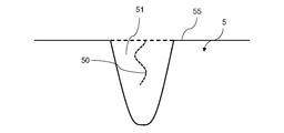
- FIG. 3 is a diagram showing an example of the groove forming step. As shown in the figure, by using a drill, an end mill, or the like on the surface 55 of the component 5 of the gas turbine in which the crack 50 has occurred, the recess 51 ( Groove) is formed. As a result, the entire crack 50 is removed.
- the recess 51 is, for example, a space having a V-shaped or U-shaped cross section.
- FIG. 4 is a diagram illustrating an example of a welding process.
- the welding process by using the welding rod 57 and the welding torch 54 containing the welding material 53, the exposed surface 52 is surely provided on the exposed surface 52 where the inside of the base material (component 5) is exposed due to the formation of the recess 51. Welding is performed so as to cover the entire surface (s11).
- the material of the welding rod 57 used for welding is an alloy containing a solid solution strengthened metal and having a higher toughness than the component 5, which is the base material.
- An example of such an alloy is a nickel-based alloy.
- this welding material 53 is a nickel-based alloy containing a dual phase nanostructured intermetallic compound alloy. That is, by adding aluminum and vanadium to nickel at a predetermined ratio and casting and solidifying the nickel-based nickel-based alloy, a eutectoid structure having a D0 22 phase (Ni 3 Al) and an L1 2 phase (Ni 3 V) is formed at a nano level. It is an alloy.
- the addition ratios of aluminum and vanadium and the addition ratios of other trace elements (boron etc.) are not particularly limited.
- the welding method in the welding process is performed as follows, for example. First, regarding the amount of heat input to the recess 51 (the amount of heat energy supplied by the welding torch 54 per unit time), heat is input to the recess 51 with a welding current of a magnitude that is used in ordinary micro TIG welding. Then, a large thermal stress is generated in the concave portion 51, and as a result, the component 5 as the base material may be cracked. Therefore, the welding current needs to be set lower than that. For example, the welding current is preferably 50 A or less.
- the moving speed (welding speed) of the welding torch 54 if the moving speed is too fast, a temperature difference between the heat input part and its surroundings (a temperature difference due to thermal diffusion) is likely to occur, so that the base metal It causes a crack of a certain component 5. Therefore, it is important that the moving speed of the welding torch 54 is not too fast. As a result, the necessary heat can be uniformly supplied to the recess 51.
- a welded portion having substantially the same shape corresponding to the recessed portion 51 is formed, and a crack generated in the component 5 is repaired.
- the inventors of the present invention conducted a welding repair test of a cast joint product using the above welding method. That is, in the present test, a combustor of a gas turbine having a damaged portion (the material is Hastelloy (registered trademark) X) was used as a test base metal, and micro TIG welding with a high-concentration nickel welding rod (welding current was maintained at 50 A or less). ) was performed to repair the damaged part by welding.
- a combustor of a gas turbine having a damaged portion the material is Hastelloy (registered trademark) X
- micro TIG welding with a high-concentration nickel welding rod welding current was maintained at 50 A or less
- the state of the test base material without damage hereinafter simply referred to as the base material
- the base material after the weld repair hereinafter referred to as the repaired member
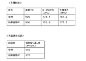
- FIG. 5 is a diagram showing a result of a welding repair test conducted by the present inventors.
- the 0.2% proof stress of the base material was 178.1 MPa, whereas the 0.2% proof stress of the repaired member was 170.3 MPa.
- the tensile strength of the base material was 187.2 MPa, whereas the tensile strength of the repaired member was 177.7 MPa. That is, regarding the tensile strength, the repaired member had a strength almost equal to that of the base material.
- the number of repeated fractures of the base metal was 555 cycles, whereas that of the repaired member (to the welded portion).
- the number of repeated breaks was 377 cycles. That is, regarding the durability against high temperature fatigue, the repaired member has a durability of about 70% of the base material, and it was found that it can sufficiently withstand the operation of the actual machine.
- a welding material having a higher toughness than the precipitation-strengthened cast alloy product which is a base material, containing a solid solution strengthened alloy.
- the base material is a precipitation-strengthened cast composite product, it is possible to buffer (releas to the outside) the thermal stress even when heat stress is applied to the weld during repair and after repair.
- the durability against thermal stress can be significantly increased, and the heat treatment that has been conventionally performed is not necessary.
- the temperature gradient in the vicinity of the weld during repair is kept relatively small, and the occurrence of thermal stress in the weld and the resulting reduction in strength of the base metal are suppressed. I thought about what I could do.
- the casting material can be repaired reliably and efficiently by appropriately combining the welding material and the welding method.
- the welding current of the micro TIG welding is set to 50 A or less, so that the repaired portion at the time of and after repairing and the damage around it (for example, cracking of the repaired portion or (Regeneration of cracks) can be reliably prevented.
- the welding material is a nickel-based alloy containing a dual phase nanostructure intermetallic compound alloy, since nickel has high toughness (ductility), After the repair, the effect of preventing damage to the repaired part and its surroundings (for example, cracking of the repaired part and re-generation of cracks) can be reliably obtained.
- the dual-phase nanostructure it is possible to obtain the effect of being resistant to high temperatures and maintaining good wear resistance and corrosion resistance.
- the welding repair method of the cast composite product of the present embodiment by performing welding so as to cover the exposed surface of the damaged part of the cast composite product, at the time of repairing and after repairing, the damaged part of the base metal and the welded part It is possible to prevent a situation where local deformation or damage occurs at the boundary and re-repair of the base material is required.
- a portion including a damaged portion is cut to form a recess (groove), and thus the damaged portion is removed. Since micro TIG welding can be performed with, it is possible to prevent damage to the repaired part and its surroundings (for example, re-generation of cracks and cracks in the repaired part) during and after repairing due to damage that occurred in the base metal. You can
- the groove is formed before performing the micro TIG welding, but without forming the groove, the overlay welding is directly performed on the damaged portion of the cast joint product. Good. Further, for damages other than cracks, such as wear (reduction in thickness) of the cast joint product, overlay welding may be directly performed on the damaged portion of the cast joint product. Further, the welding repair method according to the present embodiment is applied to general welding repair of heat-resistant alloy members such as the components of the gas turbine 10 (combustor 20, transition piece 30, stationary blades 42, moving blades 44). Can be applied.
Landscapes
- Engineering & Computer Science (AREA)
- Physics & Mathematics (AREA)
- Mechanical Engineering (AREA)
- Plasma & Fusion (AREA)
- Optics & Photonics (AREA)
- Chemical & Material Sciences (AREA)
- Materials Engineering (AREA)
- Metallurgy (AREA)
- Organic Chemistry (AREA)
- Arc Welding In General (AREA)
Abstract
L'invention concerne un procédé de réparation d'une partie endommagée d'un produit coulé renforcé par précipitation, dans lequel un matériau de soudage (53) comprenant un alliage renforcé par une solution solide et ayant une ténacité supérieure à celle d'un produit coulé renforcé par précipitation est utilisé, et dans lequel la partie endommagée est soudée par soudage TIG.
Priority Applications (4)
| Application Number | Priority Date | Filing Date | Title |
|---|---|---|---|
| JP2019530863A JP6573061B1 (ja) | 2019-02-25 | 2019-02-25 | 析出強化型鋳造合品の溶接補修方法 |
| US17/433,482 US20220134472A1 (en) | 2019-02-25 | 2019-02-25 | Precipitation-strengthened cast product welding repair method |
| PCT/JP2019/007013 WO2020174525A1 (fr) | 2019-02-25 | 2019-02-25 | Procédé de réparation par soudage pour produit coulé renforcé par précipitation |
| EP19917438.4A EP3932603A4 (fr) | 2019-02-25 | 2019-02-25 | Procédé de réparation par soudage pour produit coulé renforcé par précipitation |
Applications Claiming Priority (1)
| Application Number | Priority Date | Filing Date | Title |
|---|---|---|---|
| PCT/JP2019/007013 WO2020174525A1 (fr) | 2019-02-25 | 2019-02-25 | Procédé de réparation par soudage pour produit coulé renforcé par précipitation |
Publications (1)
| Publication Number | Publication Date |
|---|---|
| WO2020174525A1 true WO2020174525A1 (fr) | 2020-09-03 |
Family
ID=67909537
Family Applications (1)
| Application Number | Title | Priority Date | Filing Date |
|---|---|---|---|
| PCT/JP2019/007013 Ceased WO2020174525A1 (fr) | 2019-02-25 | 2019-02-25 | Procédé de réparation par soudage pour produit coulé renforcé par précipitation |
Country Status (4)
| Country | Link |
|---|---|
| US (1) | US20220134472A1 (fr) |
| EP (1) | EP3932603A4 (fr) |
| JP (1) | JP6573061B1 (fr) |
| WO (1) | WO2020174525A1 (fr) |
Citations (7)
| Publication number | Priority date | Publication date | Assignee | Title |
|---|---|---|---|---|
| WO2007086185A1 (fr) | 2006-01-30 | 2007-08-02 | Osaka Prefecture University Public Corporation | COMPOSE INTERMETALLIQUE A BASE DE Ni3Al AYANT UNE STRUCTURE DOUBLE EN DEUX PHASES, SON PROCEDE DE FABRICATION ET MATERIAU STRUCTURAL RESISTANT A LA CHALEUR |
| JP2008274314A (ja) * | 2007-04-25 | 2008-11-13 | Hitachi Ltd | ガスタービン翼およびその製造方法 |
| JP2009215649A (ja) | 2008-02-15 | 2009-09-24 | Osaka Industrial Promotion Organization | 高い硬度を有するNi基金属間化合物合金 |
| JP2011079054A (ja) * | 2009-09-10 | 2011-04-21 | Sumitomo Chemical Co Ltd | ピットの補修方法および金属部材の補修方法 |
| JP2011136344A (ja) * | 2009-12-25 | 2011-07-14 | Mitsubishi Heavy Ind Ltd | ガスタービン部材の補修方法及びガスタービン部材 |
| JP2013068085A (ja) | 2011-09-20 | 2013-04-18 | Toshiba Corp | スキーラ付きガスタービン動翼の補修方法 |
| JP2017190688A (ja) * | 2016-04-12 | 2017-10-19 | 株式会社東芝 | タービン部材、軸流タービン、およびタービン部材の製造方法 |
Family Cites Families (4)
| Publication number | Priority date | Publication date | Assignee | Title |
|---|---|---|---|---|
| US6364971B1 (en) * | 2000-01-20 | 2002-04-02 | Electric Power Research Institute | Apparatus and method of repairing turbine blades |
| US6996906B2 (en) * | 2002-12-17 | 2006-02-14 | General Electric Company | Method of repairing a turbine blade and blade repaired thereby |
| US8561298B2 (en) * | 2007-03-01 | 2013-10-22 | Siemens Energy, Inc. | Superalloy component welding at ambient temperature |
| US10960497B2 (en) * | 2017-02-01 | 2021-03-30 | Hrl Laboratories, Llc | Nanoparticle composite welding filler materials, and methods for producing the same |
-
2019
- 2019-02-25 US US17/433,482 patent/US20220134472A1/en not_active Abandoned
- 2019-02-25 WO PCT/JP2019/007013 patent/WO2020174525A1/fr not_active Ceased
- 2019-02-25 EP EP19917438.4A patent/EP3932603A4/fr not_active Withdrawn
- 2019-02-25 JP JP2019530863A patent/JP6573061B1/ja active Active
Patent Citations (7)
| Publication number | Priority date | Publication date | Assignee | Title |
|---|---|---|---|---|
| WO2007086185A1 (fr) | 2006-01-30 | 2007-08-02 | Osaka Prefecture University Public Corporation | COMPOSE INTERMETALLIQUE A BASE DE Ni3Al AYANT UNE STRUCTURE DOUBLE EN DEUX PHASES, SON PROCEDE DE FABRICATION ET MATERIAU STRUCTURAL RESISTANT A LA CHALEUR |
| JP2008274314A (ja) * | 2007-04-25 | 2008-11-13 | Hitachi Ltd | ガスタービン翼およびその製造方法 |
| JP2009215649A (ja) | 2008-02-15 | 2009-09-24 | Osaka Industrial Promotion Organization | 高い硬度を有するNi基金属間化合物合金 |
| JP2011079054A (ja) * | 2009-09-10 | 2011-04-21 | Sumitomo Chemical Co Ltd | ピットの補修方法および金属部材の補修方法 |
| JP2011136344A (ja) * | 2009-12-25 | 2011-07-14 | Mitsubishi Heavy Ind Ltd | ガスタービン部材の補修方法及びガスタービン部材 |
| JP2013068085A (ja) | 2011-09-20 | 2013-04-18 | Toshiba Corp | スキーラ付きガスタービン動翼の補修方法 |
| JP2017190688A (ja) * | 2016-04-12 | 2017-10-19 | 株式会社東芝 | タービン部材、軸流タービン、およびタービン部材の製造方法 |
Non-Patent Citations (1)
| Title |
|---|
| See also references of EP3932603A4 |
Also Published As
| Publication number | Publication date |
|---|---|
| EP3932603A4 (fr) | 2022-05-04 |
| JP6573061B1 (ja) | 2019-09-11 |
| US20220134472A1 (en) | 2022-05-05 |
| JPWO2020174525A1 (ja) | 2021-03-11 |
| EP3932603A1 (fr) | 2022-01-05 |
Similar Documents
| Publication | Publication Date | Title |
|---|---|---|
| Henderson et al. | Nickel based superalloy welding practices for industrial gas turbine applications | |
| RU2635688C2 (ru) | Способ ремонта и изготовления компонентов газотурбинного двигателя и компоненты газотурбинного двигателя, отремонтированные или изготовленные с его использованием | |
| JP6086992B2 (ja) | 超合金のクラッディング及び溶融溶接方法 | |
| US7547188B2 (en) | Ni-based alloy member, method of producing the alloy member, turbine engine part, welding material, and method of producing the welding material | |
| EP2815841B1 (fr) | Procédé pour un traitement thermique après soudure de composants soudés en superalliages consolidés par précipitation gamma prime | |
| US11180840B2 (en) | High gamma prime nickel based superalloy, its use, and method of manufacturing of turbine engine components | |
| US11072044B2 (en) | Superalloy component braze repair with isostatic solution treatment | |
| JP5537587B2 (ja) | Ni基合金溶接材料並びにこれを用いた溶接ワイヤ、溶接棒及び溶接用粉末 | |
| US6468367B1 (en) | Superalloy weld composition and repaired turbine engine component | |
| EP1473106A1 (fr) | Procédé de soudage par faisceau d'électrons incluant le traitement thermique après le soudage | |
| JP2011062749A (ja) | タービンエンジン部品を形成する超合金組成物及び方法 | |
| CA3048051A1 (fr) | Superalliage soudable a base de nickel a teneur elevee en gamma prime et procede de reparation et de fabrication de elements de moteur a turbine utilisant ledit superalliage | |
| JP2011064077A (ja) | ガスタービン部品およびその補修方法 | |
| JP6642780B1 (ja) | 析出強化型鋳造合品の溶接補修方法 | |
| JP2022529145A5 (fr) | ||
| US20120251840A1 (en) | Nickel-base weld materials, processes of using, and components formed therewith | |
| JP6573061B1 (ja) | 析出強化型鋳造合品の溶接補修方法 | |
| EP2687312B1 (fr) | Procédé de soudage d'articles en alliage | |
| JP5550298B2 (ja) | 蒸気タービンの鍛造部品用のNi基合金、蒸気タービンのタービンロータ、蒸気タービンの動翼、蒸気タービンの静翼、蒸気タービン用螺合部材、および蒸気タービン用配管 | |
| US11913093B2 (en) | High gamma prime nickel based welding material | |
| Arjakine et al. | Advanced weld repair of gas turbine hot section components | |
| Wang | Welding and repair of single crystal Ni-based superalloys | |
| HK1231013B (zh) | 修复和制造涡轮发动机部件的方法及涡轮发动机部件 | |
| Hreben et al. | Similar and Dissimilar Welding of Nickel-Based Superalloys for A-USC Steam Turbine Rotors in NextGenPower Project | |
| HK1231013A1 (en) | Method of repairing and manufacturing of turbine engine components and turbine engine components |
Legal Events
| Date | Code | Title | Description |
|---|---|---|---|
| ENP | Entry into the national phase |
Ref document number: 2019530863 Country of ref document: JP Kind code of ref document: A |
|
| 121 | Ep: the epo has been informed by wipo that ep was designated in this application |
Ref document number: 19917438 Country of ref document: EP Kind code of ref document: A1 |
|
| NENP | Non-entry into the national phase |
Ref country code: DE |
|
| ENP | Entry into the national phase |
Ref document number: 2019917438 Country of ref document: EP Effective date: 20210927 |