WO2020174530A1 - Système de régulation de fluide frigorigène et système de refroidissement - Google Patents
Système de régulation de fluide frigorigène et système de refroidissement Download PDFInfo
- Publication number
- WO2020174530A1 WO2020174530A1 PCT/JP2019/007047 JP2019007047W WO2020174530A1 WO 2020174530 A1 WO2020174530 A1 WO 2020174530A1 JP 2019007047 W JP2019007047 W JP 2019007047W WO 2020174530 A1 WO2020174530 A1 WO 2020174530A1
- Authority
- WO
- WIPO (PCT)
- Prior art keywords
- refrigerant
- opening
- pipe
- temperature
- side pipe
- Prior art date
- Legal status (The legal status is an assumption and is not a legal conclusion. Google has not performed a legal analysis and makes no representation as to the accuracy of the status listed.)
- Ceased
Links
Images






Classifications
-
- F—MECHANICAL ENGINEERING; LIGHTING; HEATING; WEAPONS; BLASTING
- F25—REFRIGERATION OR COOLING; COMBINED HEATING AND REFRIGERATION SYSTEMS; HEAT PUMP SYSTEMS; MANUFACTURE OR STORAGE OF ICE; LIQUEFACTION SOLIDIFICATION OF GASES
- F25B—REFRIGERATION MACHINES, PLANTS OR SYSTEMS; COMBINED HEATING AND REFRIGERATION SYSTEMS; HEAT PUMP SYSTEMS
- F25B25/00—Machines, plants or systems, using a combination of modes of operation covered by two or more of the groups F25B1/00 - F25B23/00
- F25B25/005—Machines, plants or systems, using a combination of modes of operation covered by two or more of the groups F25B1/00 - F25B23/00 using primary and secondary systems
-
- F—MECHANICAL ENGINEERING; LIGHTING; HEATING; WEAPONS; BLASTING
- F25—REFRIGERATION OR COOLING; COMBINED HEATING AND REFRIGERATION SYSTEMS; HEAT PUMP SYSTEMS; MANUFACTURE OR STORAGE OF ICE; LIQUEFACTION SOLIDIFICATION OF GASES
- F25B—REFRIGERATION MACHINES, PLANTS OR SYSTEMS; COMBINED HEATING AND REFRIGERATION SYSTEMS; HEAT PUMP SYSTEMS
- F25B1/00—Compression machines, plants or systems with non-reversible cycle
-
- F—MECHANICAL ENGINEERING; LIGHTING; HEATING; WEAPONS; BLASTING
- F25—REFRIGERATION OR COOLING; COMBINED HEATING AND REFRIGERATION SYSTEMS; HEAT PUMP SYSTEMS; MANUFACTURE OR STORAGE OF ICE; LIQUEFACTION SOLIDIFICATION OF GASES
- F25B—REFRIGERATION MACHINES, PLANTS OR SYSTEMS; COMBINED HEATING AND REFRIGERATION SYSTEMS; HEAT PUMP SYSTEMS
- F25B1/00—Compression machines, plants or systems with non-reversible cycle
- F25B1/10—Compression machines, plants or systems with non-reversible cycle with multi-stage compression
-
- F—MECHANICAL ENGINEERING; LIGHTING; HEATING; WEAPONS; BLASTING
- F25—REFRIGERATION OR COOLING; COMBINED HEATING AND REFRIGERATION SYSTEMS; HEAT PUMP SYSTEMS; MANUFACTURE OR STORAGE OF ICE; LIQUEFACTION SOLIDIFICATION OF GASES
- F25B—REFRIGERATION MACHINES, PLANTS OR SYSTEMS; COMBINED HEATING AND REFRIGERATION SYSTEMS; HEAT PUMP SYSTEMS
- F25B41/00—Fluid-circulation arrangements
- F25B41/20—Disposition of valves, e.g. of on-off valves or flow control valves
-
- F—MECHANICAL ENGINEERING; LIGHTING; HEATING; WEAPONS; BLASTING
- F25—REFRIGERATION OR COOLING; COMBINED HEATING AND REFRIGERATION SYSTEMS; HEAT PUMP SYSTEMS; MANUFACTURE OR STORAGE OF ICE; LIQUEFACTION SOLIDIFICATION OF GASES
- F25B—REFRIGERATION MACHINES, PLANTS OR SYSTEMS; COMBINED HEATING AND REFRIGERATION SYSTEMS; HEAT PUMP SYSTEMS
- F25B41/00—Fluid-circulation arrangements
- F25B41/40—Fluid line arrangements
- F25B41/42—Arrangements for diverging or converging flows, e.g. branch lines or junctions
-
- F—MECHANICAL ENGINEERING; LIGHTING; HEATING; WEAPONS; BLASTING
- F25—REFRIGERATION OR COOLING; COMBINED HEATING AND REFRIGERATION SYSTEMS; HEAT PUMP SYSTEMS; MANUFACTURE OR STORAGE OF ICE; LIQUEFACTION SOLIDIFICATION OF GASES
- F25B—REFRIGERATION MACHINES, PLANTS OR SYSTEMS; COMBINED HEATING AND REFRIGERATION SYSTEMS; HEAT PUMP SYSTEMS
- F25B43/00—Arrangements for separating or purifying gases or liquids; Arrangements for vaporising the residuum of liquid refrigerant, e.g. by heat
-
- F—MECHANICAL ENGINEERING; LIGHTING; HEATING; WEAPONS; BLASTING
- F25—REFRIGERATION OR COOLING; COMBINED HEATING AND REFRIGERATION SYSTEMS; HEAT PUMP SYSTEMS; MANUFACTURE OR STORAGE OF ICE; LIQUEFACTION SOLIDIFICATION OF GASES
- F25B—REFRIGERATION MACHINES, PLANTS OR SYSTEMS; COMBINED HEATING AND REFRIGERATION SYSTEMS; HEAT PUMP SYSTEMS
- F25B45/00—Arrangements for charging or discharging refrigerant
-
- F—MECHANICAL ENGINEERING; LIGHTING; HEATING; WEAPONS; BLASTING
- F25—REFRIGERATION OR COOLING; COMBINED HEATING AND REFRIGERATION SYSTEMS; HEAT PUMP SYSTEMS; MANUFACTURE OR STORAGE OF ICE; LIQUEFACTION SOLIDIFICATION OF GASES
- F25B—REFRIGERATION MACHINES, PLANTS OR SYSTEMS; COMBINED HEATING AND REFRIGERATION SYSTEMS; HEAT PUMP SYSTEMS
- F25B49/00—Arrangement or mounting of control or safety devices
- F25B49/02—Arrangement or mounting of control or safety devices for compression type machines, plants or systems
-
- F—MECHANICAL ENGINEERING; LIGHTING; HEATING; WEAPONS; BLASTING
- F25—REFRIGERATION OR COOLING; COMBINED HEATING AND REFRIGERATION SYSTEMS; HEAT PUMP SYSTEMS; MANUFACTURE OR STORAGE OF ICE; LIQUEFACTION SOLIDIFICATION OF GASES
- F25B—REFRIGERATION MACHINES, PLANTS OR SYSTEMS; COMBINED HEATING AND REFRIGERATION SYSTEMS; HEAT PUMP SYSTEMS
- F25B9/00—Compression machines, plants or systems, in which the refrigerant is air or other gas of low boiling point
- F25B9/002—Compression machines, plants or systems, in which the refrigerant is air or other gas of low boiling point characterised by the refrigerant
- F25B9/008—Compression machines, plants or systems, in which the refrigerant is air or other gas of low boiling point characterised by the refrigerant the refrigerant being carbon dioxide
-
- F—MECHANICAL ENGINEERING; LIGHTING; HEATING; WEAPONS; BLASTING
- F25—REFRIGERATION OR COOLING; COMBINED HEATING AND REFRIGERATION SYSTEMS; HEAT PUMP SYSTEMS; MANUFACTURE OR STORAGE OF ICE; LIQUEFACTION SOLIDIFICATION OF GASES
- F25B—REFRIGERATION MACHINES, PLANTS OR SYSTEMS; COMBINED HEATING AND REFRIGERATION SYSTEMS; HEAT PUMP SYSTEMS
- F25B2309/00—Gas cycle refrigeration machines
- F25B2309/06—Compression machines, plants or systems characterised by the refrigerant being carbon dioxide
-
- F—MECHANICAL ENGINEERING; LIGHTING; HEATING; WEAPONS; BLASTING
- F25—REFRIGERATION OR COOLING; COMBINED HEATING AND REFRIGERATION SYSTEMS; HEAT PUMP SYSTEMS; MANUFACTURE OR STORAGE OF ICE; LIQUEFACTION SOLIDIFICATION OF GASES
- F25B—REFRIGERATION MACHINES, PLANTS OR SYSTEMS; COMBINED HEATING AND REFRIGERATION SYSTEMS; HEAT PUMP SYSTEMS
- F25B2309/00—Gas cycle refrigeration machines
- F25B2309/06—Compression machines, plants or systems characterised by the refrigerant being carbon dioxide
- F25B2309/061—Compression machines, plants or systems characterised by the refrigerant being carbon dioxide with cycle highest pressure above the supercritical pressure
-
- F—MECHANICAL ENGINEERING; LIGHTING; HEATING; WEAPONS; BLASTING
- F25—REFRIGERATION OR COOLING; COMBINED HEATING AND REFRIGERATION SYSTEMS; HEAT PUMP SYSTEMS; MANUFACTURE OR STORAGE OF ICE; LIQUEFACTION SOLIDIFICATION OF GASES
- F25B—REFRIGERATION MACHINES, PLANTS OR SYSTEMS; COMBINED HEATING AND REFRIGERATION SYSTEMS; HEAT PUMP SYSTEMS
- F25B2400/00—Component parts or details not otherwise provided for in this subclass
- F25B2400/13—Economisers
-
- F—MECHANICAL ENGINEERING; LIGHTING; HEATING; WEAPONS; BLASTING
- F25—REFRIGERATION OR COOLING; COMBINED HEATING AND REFRIGERATION SYSTEMS; HEAT PUMP SYSTEMS; MANUFACTURE OR STORAGE OF ICE; LIQUEFACTION SOLIDIFICATION OF GASES
- F25B—REFRIGERATION MACHINES, PLANTS OR SYSTEMS; COMBINED HEATING AND REFRIGERATION SYSTEMS; HEAT PUMP SYSTEMS
- F25B2400/00—Component parts or details not otherwise provided for in this subclass
- F25B2400/16—Receivers
-
- F—MECHANICAL ENGINEERING; LIGHTING; HEATING; WEAPONS; BLASTING
- F25—REFRIGERATION OR COOLING; COMBINED HEATING AND REFRIGERATION SYSTEMS; HEAT PUMP SYSTEMS; MANUFACTURE OR STORAGE OF ICE; LIQUEFACTION SOLIDIFICATION OF GASES
- F25B—REFRIGERATION MACHINES, PLANTS OR SYSTEMS; COMBINED HEATING AND REFRIGERATION SYSTEMS; HEAT PUMP SYSTEMS
- F25B2400/00—Component parts or details not otherwise provided for in this subclass
- F25B2400/24—Thermal storage element
-
- F—MECHANICAL ENGINEERING; LIGHTING; HEATING; WEAPONS; BLASTING
- F25—REFRIGERATION OR COOLING; COMBINED HEATING AND REFRIGERATION SYSTEMS; HEAT PUMP SYSTEMS; MANUFACTURE OR STORAGE OF ICE; LIQUEFACTION SOLIDIFICATION OF GASES
- F25B—REFRIGERATION MACHINES, PLANTS OR SYSTEMS; COMBINED HEATING AND REFRIGERATION SYSTEMS; HEAT PUMP SYSTEMS
- F25B2600/00—Control issues
- F25B2600/02—Compressor control
- F25B2600/021—Inverters therefor
-
- F—MECHANICAL ENGINEERING; LIGHTING; HEATING; WEAPONS; BLASTING
- F25—REFRIGERATION OR COOLING; COMBINED HEATING AND REFRIGERATION SYSTEMS; HEAT PUMP SYSTEMS; MANUFACTURE OR STORAGE OF ICE; LIQUEFACTION SOLIDIFICATION OF GASES
- F25B—REFRIGERATION MACHINES, PLANTS OR SYSTEMS; COMBINED HEATING AND REFRIGERATION SYSTEMS; HEAT PUMP SYSTEMS
- F25B2600/00—Control issues
- F25B2600/05—Refrigerant levels
-
- F—MECHANICAL ENGINEERING; LIGHTING; HEATING; WEAPONS; BLASTING
- F25—REFRIGERATION OR COOLING; COMBINED HEATING AND REFRIGERATION SYSTEMS; HEAT PUMP SYSTEMS; MANUFACTURE OR STORAGE OF ICE; LIQUEFACTION SOLIDIFICATION OF GASES
- F25B—REFRIGERATION MACHINES, PLANTS OR SYSTEMS; COMBINED HEATING AND REFRIGERATION SYSTEMS; HEAT PUMP SYSTEMS
- F25B2600/00—Control issues
- F25B2600/25—Control of valves
- F25B2600/2501—Bypass valves
-
- F—MECHANICAL ENGINEERING; LIGHTING; HEATING; WEAPONS; BLASTING
- F25—REFRIGERATION OR COOLING; COMBINED HEATING AND REFRIGERATION SYSTEMS; HEAT PUMP SYSTEMS; MANUFACTURE OR STORAGE OF ICE; LIQUEFACTION SOLIDIFICATION OF GASES
- F25B—REFRIGERATION MACHINES, PLANTS OR SYSTEMS; COMBINED HEATING AND REFRIGERATION SYSTEMS; HEAT PUMP SYSTEMS
- F25B2600/00—Control issues
- F25B2600/25—Control of valves
- F25B2600/2507—Flow-diverting valves
-
- F—MECHANICAL ENGINEERING; LIGHTING; HEATING; WEAPONS; BLASTING
- F25—REFRIGERATION OR COOLING; COMBINED HEATING AND REFRIGERATION SYSTEMS; HEAT PUMP SYSTEMS; MANUFACTURE OR STORAGE OF ICE; LIQUEFACTION SOLIDIFICATION OF GASES
- F25B—REFRIGERATION MACHINES, PLANTS OR SYSTEMS; COMBINED HEATING AND REFRIGERATION SYSTEMS; HEAT PUMP SYSTEMS
- F25B2600/00—Control issues
- F25B2600/25—Control of valves
- F25B2600/2519—On-off valves
-
- F—MECHANICAL ENGINEERING; LIGHTING; HEATING; WEAPONS; BLASTING
- F25—REFRIGERATION OR COOLING; COMBINED HEATING AND REFRIGERATION SYSTEMS; HEAT PUMP SYSTEMS; MANUFACTURE OR STORAGE OF ICE; LIQUEFACTION SOLIDIFICATION OF GASES
- F25B—REFRIGERATION MACHINES, PLANTS OR SYSTEMS; COMBINED HEATING AND REFRIGERATION SYSTEMS; HEAT PUMP SYSTEMS
- F25B2700/00—Sensing or detecting of parameters; Sensors therefor
- F25B2700/19—Pressures
- F25B2700/193—Pressures of the compressor
- F25B2700/1931—Discharge pressures
-
- F—MECHANICAL ENGINEERING; LIGHTING; HEATING; WEAPONS; BLASTING
- F25—REFRIGERATION OR COOLING; COMBINED HEATING AND REFRIGERATION SYSTEMS; HEAT PUMP SYSTEMS; MANUFACTURE OR STORAGE OF ICE; LIQUEFACTION SOLIDIFICATION OF GASES
- F25B—REFRIGERATION MACHINES, PLANTS OR SYSTEMS; COMBINED HEATING AND REFRIGERATION SYSTEMS; HEAT PUMP SYSTEMS
- F25B2700/00—Sensing or detecting of parameters; Sensors therefor
- F25B2700/19—Pressures
- F25B2700/193—Pressures of the compressor
- F25B2700/1933—Suction pressures
-
- F—MECHANICAL ENGINEERING; LIGHTING; HEATING; WEAPONS; BLASTING
- F25—REFRIGERATION OR COOLING; COMBINED HEATING AND REFRIGERATION SYSTEMS; HEAT PUMP SYSTEMS; MANUFACTURE OR STORAGE OF ICE; LIQUEFACTION SOLIDIFICATION OF GASES
- F25B—REFRIGERATION MACHINES, PLANTS OR SYSTEMS; COMBINED HEATING AND REFRIGERATION SYSTEMS; HEAT PUMP SYSTEMS
- F25B2700/00—Sensing or detecting of parameters; Sensors therefor
- F25B2700/21—Temperatures
- F25B2700/2115—Temperatures of a compressor or the drive means therefor
- F25B2700/21151—Temperatures of a compressor or the drive means therefor at the suction side of the compressor
-
- F—MECHANICAL ENGINEERING; LIGHTING; HEATING; WEAPONS; BLASTING
- F25—REFRIGERATION OR COOLING; COMBINED HEATING AND REFRIGERATION SYSTEMS; HEAT PUMP SYSTEMS; MANUFACTURE OR STORAGE OF ICE; LIQUEFACTION SOLIDIFICATION OF GASES
- F25B—REFRIGERATION MACHINES, PLANTS OR SYSTEMS; COMBINED HEATING AND REFRIGERATION SYSTEMS; HEAT PUMP SYSTEMS
- F25B2700/00—Sensing or detecting of parameters; Sensors therefor
- F25B2700/21—Temperatures
- F25B2700/2117—Temperatures of an evaporator
-
- F—MECHANICAL ENGINEERING; LIGHTING; HEATING; WEAPONS; BLASTING
- F25—REFRIGERATION OR COOLING; COMBINED HEATING AND REFRIGERATION SYSTEMS; HEAT PUMP SYSTEMS; MANUFACTURE OR STORAGE OF ICE; LIQUEFACTION SOLIDIFICATION OF GASES
- F25B—REFRIGERATION MACHINES, PLANTS OR SYSTEMS; COMBINED HEATING AND REFRIGERATION SYSTEMS; HEAT PUMP SYSTEMS
- F25B49/00—Arrangement or mounting of control or safety devices
- F25B49/02—Arrangement or mounting of control or safety devices for compression type machines, plants or systems
- F25B49/022—Compressor control arrangements
-
- H—ELECTRICITY
- H10—SEMICONDUCTOR DEVICES; ELECTRIC SOLID-STATE DEVICES NOT OTHERWISE PROVIDED FOR
- H10P—GENERIC PROCESSES OR APPARATUS FOR THE MANUFACTURE OR TREATMENT OF DEVICES COVERED BY CLASS H10
- H10P72/00—Handling or holding of wafers, substrates or devices during manufacture or treatment thereof
- H10P72/04—Apparatus for manufacture or treatment
- H10P72/0402—Apparatus for fluid treatment
-
- H—ELECTRICITY
- H10—SEMICONDUCTOR DEVICES; ELECTRIC SOLID-STATE DEVICES NOT OTHERWISE PROVIDED FOR
- H10P—GENERIC PROCESSES OR APPARATUS FOR THE MANUFACTURE OR TREATMENT OF DEVICES COVERED BY CLASS H10
- H10P72/00—Handling or holding of wafers, substrates or devices during manufacture or treatment thereof
- H10P72/04—Apparatus for manufacture or treatment
- H10P72/0431—Apparatus for thermal treatment
- H10P72/0434—Apparatus for thermal treatment mainly by convection
-
- Y—GENERAL TAGGING OF NEW TECHNOLOGICAL DEVELOPMENTS; GENERAL TAGGING OF CROSS-SECTIONAL TECHNOLOGIES SPANNING OVER SEVERAL SECTIONS OF THE IPC; TECHNICAL SUBJECTS COVERED BY FORMER USPC CROSS-REFERENCE ART COLLECTIONS [XRACs] AND DIGESTS
- Y02—TECHNOLOGIES OR APPLICATIONS FOR MITIGATION OR ADAPTATION AGAINST CLIMATE CHANGE
- Y02B—CLIMATE CHANGE MITIGATION TECHNOLOGIES RELATED TO BUILDINGS, e.g. HOUSING, HOUSE APPLIANCES OR RELATED END-USER APPLICATIONS
- Y02B30/00—Energy efficient heating, ventilation or air conditioning [HVAC]
- Y02B30/70—Efficient control or regulation technologies, e.g. for control of refrigerant flow, motor or heating
Definitions
- the present invention relates to a refrigerant control system and a cooling system.
- the device of Patent Document 1 is a high-source refrigeration cycle in which a high-source side compressor, a high-source side condenser, a high-source side expansion device, and a high-source side evaporator are connected by piping to circulate refrigerant,
- a low-source refrigeration cycle in which a refrigerant is circulated by connecting a side compressor, an auxiliary radiator, a low-source side condenser, a low-source side expansion device, and a low-source side evaporator to a refrigerant, and a high-source side evaporator and a low-level side
- a condenser and a cascade condenser configured to be coupled to each other so that heat can be exchanged between the passing refrigerants.
- the solenoid valve is opened so that the inside of the low-source refrigeration cycle is opened.
- the present invention has been made in view of the above, and an object of the present invention is to provide a refrigerant control system and a cooling system capable of maintaining usability.
- the refrigerant control system is a circulation flow path connected to a compression unit, and includes a refrigerant compressed by the compression unit and a cooling target.
- a refrigerant control system for controlling the refrigerant flowing in a circulation passage for circulating the refrigerant so that heat can be exchanged, the storage means for storing the refrigerant, and the circulation passage. Is a first pipe connected to an outlet-side pipe located on the outlet side of the compression means, and the refrigerant in the outlet-side pipe is stored through the first pipe.
- a second opening/closing valve capable of switching whether to flow into the pipe and opening/closing for performing opening/closing control of the first opening/closing valve and the second opening/closing valve based on a set temperature of the cooling target set by a predetermined method. And a control means.
- the refrigerant control system according to claim 2 is the refrigerant control system according to claim 1, wherein the opening/closing control unit is configured to perform the first opening/closing when the preset temperature of the cooling target is higher than a critical temperature of the refrigerant.
- the valve is opened and the second opening/closing valve is closed.
- the first opening/closing valve is closed and the second opening/closing valve is opened.
- the refrigerant control system is the refrigerant control system according to claim 2, wherein the opening/closing control means is configured to operate when the operating pressure value of the compression means obtained by a predetermined method exceeds a threshold value, or the cooling is performed.
- the opening/closing control means is configured to operate when the operating pressure value of the compression means obtained by a predetermined method exceeds a threshold value, or the cooling is performed.
- the first opening/closing valve is opened and the second opening/closing valve is closed, and the operating pressure value of the compression means is set to a threshold value.
- the first opening/closing valve is closed and the second opening/closing valve is opened.
- the refrigerant control system according to claim 4 is the refrigerant control system according to any one of claims 1 to 3, further comprising temperature adjusting means for adjusting the temperature of the refrigerant in the storage means.
- the refrigerant control system according to claim 5 is the refrigerant control system according to any one of claims 1 to 4, wherein the refrigerant is carbon dioxide.
- the refrigerant control system according to claim 6 is the refrigerant control system according to any one of claims 1 to 5, wherein the cooling target is a cooling refrigerant for a semiconductor manufacturing system.
- the cooling system according to claim 7, which is a cooling system for cooling the object to be cooled by using the refrigerant, is connected to the compression means for compressing the refrigerant, and is connected to the compression means.
- a circulation flow path having a cooling target side pipe located on the target side, and a circulation flow path for circulating the refrigerant so that heat exchange between the refrigerant compressed by the compression means and the cooling target is possible.
- the cooling system according to claim 8 is the cooling system according to claim 7, wherein the heat exchange means is cooled by the first heat exchange means capable of cooling the cooling target and the first heat exchange means.
- a second heat exchange unit capable of heating the cooling target wherein the cooling target side pipe is connected to the first cooling target side pipe located on the first heat exchange unit side, and the second heat exchange unit side.
- a part upstream of the heat exchange means a third pipe connected to the inlet side pipe, and a third opening/closing valve provided in the third pipe, wherein the refrigerant in the cooling target side pipe is A third opening/closing valve capable of adjusting the amount of flow into the inlet side pipe, and the opening/closing control means controls the opening degree of the third opening/closing valve based on the detection result of the detection means.
- the cooling system according to claim 9 is the cooling system according to claim 8, wherein the fourth opening/closing valve is provided in a portion of the first cooling target side pipe upstream of the first heat exchange means.
- a fourth opening/closing valve capable of adjusting the amount of the refrigerant in the first cooling target side pipe flowing into the first heat exchange means, and a downstream side of the second heat exchange means in the second cooling target side pipe
- a fifth on-off valve capable of adjusting the amount of the refrigerant, which has been heat-exchanged by the second heat exchange means, flowing into the inflow port side pipe.
- the opening/closing control means controls the opening degree of the fourth opening/closing valve and the fifth opening/closing valve based on the temperature of the cooling target acquired by a predetermined method.
- the cooling system according to claim 10 is the cooling system according to any one of claims 7 to 9, wherein the first cooling target side pipe is provided with a portion in the upstream side of the first heat exchange means.
- Refrigerant heat exchanging means for exchanging heat between the refrigerant and the refrigerant in a portion of the second cooling target side pipe downstream of the second heat exchanging means is provided.
- the cooling system according to claim 11 is the cooling system according to any one of claims 7 to 10, based on the detection result of the detection means and the temperature of the cooling target acquired by a predetermined method.
- a compression control means for controlling the compression means is provided.
- the first pipe is connected to the outlet side pipe, and the inside of the outlet side pipe is connected via the first pipe.
- a first pipe for flowing the refrigerant into the storage means and a second pipe connected to the inlet side pipe, for allowing the refrigerant in the storage means to flow into the inlet side pipe through the second pipe. Since the second pipe is provided, the temperature in the storage means is kept above the critical temperature of the refrigerant (or superheated steam) by the heat of the refrigerant flowing into the storage means while suppressing the pressure in the circulation passage from becoming excessive.
- the amount of the refrigerant in the circulation passage is decreasing due to the condensation of the refrigerant in the storage means.
- the first pipe is connected to the outlet side pipe, it is possible to store the refrigerant of high compression and high density as compared with the case where the first pipe is connected to the inlet side pipe, and It is possible to effectively prevent the pressure from becoming excessive and the excessive increase in the cooling capacity when the set temperature of the cooling target is high.
- the refrigerant in the storage means can be caused to flow into the inlet side pipe, and the temperature of the inside of the inlet side pipe can be raised by the heat of the introduced refrigerant, so that saturated vapor can flow into the compression means.
- a first opening/closing valve capable of switching whether or not the refrigerant in the outlet side pipe flows into the storage means
- a second opening/closing valve capable of switching whether or not the refrigerant in the storage means flows into the inlet side pipe. Since the opening/closing valve and the opening/closing control means for controlling the opening/closing of the first opening/closing valve and the second opening/closing valve based on the set temperature of the cooling target set by the predetermined method are provided, based on the set temperature of the cooling target.
- the refrigerant By controlling the opening/closing of the first opening/closing valve and the second opening/closing valve, the refrigerant can effectively flow in and out of the storage means. From the above, it becomes easier to maintain the function of the compression unit, the function of the storage unit, and the function of the circulation flow path, as compared with the conventional technology (the technology of simply flowing the refrigerant in the low-temperature refrigeration cycle into the expansion tank). The usability of the refrigerant control system (or the cooling system) can be maintained.
- the opening/closing control means opens the first opening/closing valve and closes the second opening/closing valve when the set temperature of the cooling target exceeds the critical temperature of the refrigerant.
- the first opening/closing valve is closed and the second opening/closing valve is opened. Therefore, when the set temperature of the cooling target is higher than the critical temperature of the refrigerant.
- a high-compression and high-density refrigerant from the outlet side pipe can be flowed into the storage means, and the excessive cooling capacity in the case where the pressure in the circulation channel becomes excessive and the set temperature of the cooling target is high The rise can be prevented more effectively.
- the refrigerant in the storage means can be made to flow into the inlet side pipe, and the amount of refrigerant in the circulation flow path can be increased accordingly. As a result, it is possible to recover the pressure in the circulation flow channel that has decreased with the decrease in the set temperature of the cooling target, and it becomes easier to maintain the function of the circulation flow channel.
- the opening/closing control of the first opening/closing valve and the second opening/closing valve is performed based on the set temperature of the cooling target and the operating pressure value of the compression means.
- the storage means is suppressed while suppressing the pressure in the circulation passage from becoming excessive. Due to the heat of the refrigerant that has flowed into the storage means, the temperature inside the storage means can be easily maintained above the critical temperature of the refrigerant (or the superheated steam temperature).
- the temperature adjusting means for adjusting the temperature of the refrigerant in the storage means since the temperature adjusting means for adjusting the temperature of the refrigerant in the storage means is provided, the temperature of the refrigerant in the storage means can be adjusted. It becomes easy to suppress that the amount of the refrigerant in the circulation passage decreases due to the condensation of the.
- the refrigerant is carbon dioxide, it is possible to avoid the pressure in the circulation passage from becoming excessive even if it expands more easily than CFC gas.
- the pressure in the circulation channel becomes excessive even if the temperature range of the object to be cooled is relatively wide. This can be avoided, and it is possible to suppress a decrease in the flow rate of the refrigerant in the circulation passage due to the condensation of the refrigerant in the storage means.
- the heat exchanging means is capable of cooling the object to be cooled, and second heat exchanging means capable of heating the object to be cooled cooled by the first heat exchanging means.
- the first cooling target side pipe located on the first heat exchange means side and the second cooling target side pipe located on the second heat exchange means side Adjusting the amount of the refrigerant in the cooling target side pipe into the inlet side pipe, and the third pipe connected to the upstream side of the first heat exchange means in the cooling target side pipe, the inlet side pipe Since the opening/closing control means controls the opening degree of the third opening/closing valve based on the detection result of the detecting means, the opening degree of the third opening/closing valve based on the temperature of the refrigerant. Adjustment can be performed, and the temperature of the refrigerant in the outlet side pipe can be efficiently adjusted.
- the fourth opening/closing valve capable of adjusting the amount of the refrigerant in the first cooling target side pipe flowing into the first heat exchange means is heat-exchanged by the second heat exchange means.
- a fifth on-off valve capable of adjusting the amount of the refrigerant flowing into the inflow port side pipe, and the on-off control means based on the temperature of the cooling target acquired by the predetermined method, the fourth on-off valve and the fifth on-off valve. Since the opening degree of the on-off valve is controlled, the temperature of the refrigerant in the cooling target side pipe can be adjusted so that the temperature of the cooling target becomes the set temperature of the cooling target, and the cooling target can be efficiently cooled.
- the refrigerant in the upstream side of the first heat exchange means in the first cooling target side pipe and the downstream side of the second heat exchange means in the second cooling target side pipe Since the refrigerant heat exchange means for exchanging heat with the refrigerant in the side portion is provided, the temperature of the refrigerant in the portion of the second cooling target side pipe on the downstream side of the second heat exchange means can be increased. Therefore, the dry refrigerant can be made to flow into the compression means.
- the cooling system since the cooling system includes the compression control unit that controls the compression unit based on the detection result of the detection unit and the temperature of the cooling target acquired by the predetermined method, the temperature of the refrigerant is reduced. Also, the compression means can be controlled based on the temperature of the cooling target, and the compression means can be efficiently controlled.
- FIG. 7 is a flowchart of a control process according to the embodiment. It is a figure which shows the flow of the 1st refrigerant
- Fig. 4 is a diagram showing a state in which the first on-off valve is closed and the second on-off valve is opened. It is a flow chart of the 1st temperature adjustment processing. It is a flow chart of the 2nd temperature adjustment processing.
- the embodiment is generally a refrigerant control system that controls a refrigerant flowing in a circulation passage for circulating the refrigerant so that heat exchange between the refrigerant compressed by the compression means and a cooling target is possible, And a cooling system.
- the "refrigerant” means a medium used for cooling a cooling target, and includes, for example, a gaseous refrigerant (for example, carbon dioxide, chlorofluorocarbon, air, etc.), a liquid refrigerant (for example, water). Etc.) and the like, but in the embodiment, carbon dioxide will be described.
- cooling target means a target to be cooled, and for example, the device itself (or the system itself), a cooling coolant for the device (or the system) (as an example, a gaseous or liquid cooling coolant). ) And the like, the embodiment will be described as a cooling medium for the semiconductor manufacturing system (specifically, a liquid cooling medium).
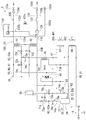
- FIG. 1 is a schematic diagram showing a cooling system according to an embodiment of the present invention.
- the X direction in FIG. 1 is the left-right direction of the cooling system (+X direction is the left direction of the cooling system, ⁇ X direction is the right direction of the cooling system), and the Y direction of FIG. 1 is the front-back direction of the cooling system.
- the +Y direction is the front direction of the cooling system
- the -Y direction is the rear direction of the cooling system
- the direction orthogonal to the X direction and the Y direction is the vertical direction
- the direction reaching the front side of FIG. 1 is the upward direction of the cooling system
- the direction reaching the back side of the paper in FIG. 1 is referred to as the downward direction of the cooling system.
- the cooling system 1 is a system for cooling the second refrigerant using the first refrigerant, and as shown in FIG. 1, the first cooling system 10, the second cooling system 100, the third cooling system 200, and The control device 300 of FIG. 2 described later is provided.
- the "first refrigerant” is used to cool the second refrigerant and is circulated by the circulation unit 50 described later.
- the “second refrigerant” is cooled by the first refrigerant and is sent out by the sending flow path 131 of the second cooling system 100 described later.
- the first refrigerant described above corresponds to the "refrigerant" in the claims
- the second refrigerant described above corresponds to the "cooling target" in the claims.
- the first cooling system 10 is a system for exchanging heat between the first refrigerant and each of the second refrigerant and the third refrigerant, and as shown in FIG. 1, the compression unit 20, the storage unit 30, and the first heat exchange unit. 41 to 6th heat exchange part 46, a removal part 47, and a circulation part 50 are provided.
- the “third refrigerant” is used to cool the first refrigerant, and is sent out by the first delivery passage 201 or the second delivery passage 202 of the third cooling system 200 described later.
- it is a concept that includes, for example, a gaseous refrigerant, a liquid refrigerant, and the like, in the embodiment, it will be described as industrial water.
- the compression unit 20 is a compression unit that compresses the first refrigerant.
- the compression unit 20 is configured using, for example, a known compressor (as an example, a frequency control operation type two-stage compressor such as a compressor having an inverter drive circuit), and more specifically, the compression unit main body 21.
- the compression unit main body 21 is a basic structure of the compression unit 20, and is configured in a hollow shape.
- the first outlet 22 is an opening for letting out the first refrigerant in the compression unit main body 21 into a first circulation flow path 61 described later.
- the first inflow port 23 is an opening for allowing the first refrigerant in the first circulation flow path 61, which will be described later, to flow into the compression unit main body 21.
- the second outlet 24 is an opening for letting out the first refrigerant in the compression unit main body 21 into a second circulation flow channel 81 described later.
- the second inflow port 25 is an opening for allowing the first refrigerant in the second circulation flow path 81, which will be described later, to flow into the compression unit main body 21.
- the specific operation content of the compression unit 20 is arbitrary, but in the embodiment, it is as follows. That is, first, the first refrigerant that has flowed into the compression unit main body 21 from the later-described first circulation flow path 61 through the first inflow port 23 is compressed, and the compressed first refrigerant is passed through the second outflow port 24. It is made to flow out to the 2nd circulation flow path 81 mentioned later (henceforth a "1st compression operation"). Next, the first refrigerant that has flowed into the compression unit main body 21 from the second circulation flow path 81 described below through the second inflow port 25 is compressed, and the compressed first refrigerant is passed through the first outflow port 22.
- the 2nd compression operation It is made to flow out to the 1st circulation channel 61 mentioned below (it is hereafter called "the 2nd compression operation"). After that, the operation cycle including the first compression operation and the second compression operation is repeated.
- the first refrigerant that has been compressed twice by the compression unit 20 can flow out to the first circulation flow path 61, which will be described later, and the first refrigerant is compressed as compared with the case where the compression operation is performed only once. Can be efficiently performed.
- the storage unit 30 is a storage unit that stores the first refrigerant.
- the storage unit 30 is configured by using, for example, a well-known refrigerant reservoir (as an example, a hollow cylindrical expansion tank having an inflow/outflow port (not shown) for inflowing/outflowing the first refrigerant).
- a well-known refrigerant reservoir as an example, a hollow cylindrical expansion tank having an inflow/outflow port (not shown) for inflowing/outflowing the first refrigerant.
- the compression unit 20 is installed closer to the second cooling system 100.
- the specific size (for example, diameter and height) of the storage unit 30 is arbitrary, for example, it is desirable to make the storage unit 30 as small as possible to store a desired amount of the first refrigerant. You may set based on etc.
- the first heat exchange section 41 performs heat exchange between the first refrigerant and the second refrigerant in the first circulation flow path 61, which will be described later, and is a first heat exchange means capable of cooling the second refrigerant. ..
- the first heat exchange section 41 is configured by using, for example, a known heat exchanger (e.g., evaporator), and as shown in FIG. 1, a position near the second cooling system 100 (in FIG. 1, It is installed at a position on the upstream side of the delivery channel 131 described later).
- the second heat exchange section 42 exchanges heat between the first refrigerant and the second refrigerant in the first circulation flow path 61, which will be described later, and the second refrigerant cooled by the first heat exchange section 41 is used. It is a heatable second heat exchange means.
- the second heat exchange unit 42 is configured by using, for example, a known heat exchanger (a plate heat exchanger as an example) or the like, and as shown in FIG. 1, a position near the second cooling system 100 (see FIG. In No. 1, it is installed at a position on the downstream side of the delivery channel 131 described later).
- the second heat exchange section 42 as described above can heat the second refrigerant that has been overcooled by the first heat exchange section 41, and it becomes easier to maintain the temperature of the downstream side portion of the delivery passage 131, which will be described later, at the desired temperature. ..
- the above-mentioned "1st heat exchange part 41" and “2nd heat exchange part 42" respond
- the third heat exchange section 43 performs heat exchange between the first refrigerant and the third refrigerant in the first circulation flow path 61, which will be described later, and is a third heat exchange means capable of cooling the first refrigerant. ..
- the third heat exchange section 43 is configured by using, for example, a known heat exchanger, and is installed in the vicinity of the third cooling system 200 as shown in FIG.
- the fourth heat exchange section 44 performs heat exchange between the first refrigerant and the third refrigerant in the second circulation flow path 81 described later, and is a fourth heat exchange means capable of cooling the first refrigerant. ..
- the fourth heat exchange unit 44 is configured by using, for example, a known heat exchanger, and as shown in FIG. 1, a position near the third cooling system 200 (in FIG. 1, the third heat exchange unit 43). It is installed in a different position).
- the fifth heat exchange unit 45 includes a first refrigerant in a portion of the first cooling target side pipe 63a, which will be described later, on the upstream side of the first heat exchange unit 41, and a first refrigerant in a fourth sub-pipe 71d, which will be described later. Is a fifth heat exchange unit capable of cooling the first refrigerant in the first cooling target side pipe 63a, which will be described later.
- the fifth heat exchange unit 45 is configured by using, for example, a known heat exchanger, and is installed between the second heat exchange unit 42 and the third heat exchange unit 43 as shown in FIG. Has been done.
- the sixth heat exchange unit 46 includes the first refrigerant in a portion of the first cooling target side pipe 63a, which will be described later, on the upstream side of the first heat exchange unit 41, and the second heat in the second cooling target side pipe 63b, which will be described later. It is a refrigerant heat exchanging means for exchanging heat with the first refrigerant in the portion on the downstream side of the exchanging section 42 and capable of heating the first refrigerant in the second cooling object side pipe 63b described later.
- the sixth heat exchange section 46 is configured by using, for example, a known heat exchanger, and as shown in FIG. 1, the storage section 30 and the first heat exchange section 41 (or the second heat exchange section 42). It is installed between and.
- the temperature of the first refrigerant in the portion of the second cooling target side pipe 63b, which will be described later, on the downstream side of the second heat exchanging unit 42 can be increased, and the compression unit 20. It is possible to allow the dried first refrigerant to flow in.
- the removing unit 47 is a removing unit for removing foreign matter (for example, dust, dust, etc.) or water contained in the first refrigerant in the first circulation flow channel 61 described later.
- the removing unit 47 is configured by using, for example, a known refrigerant remover (for example, a filter dryer), and as shown in FIG. 1, a third heat exchanging unit 43 and a fifth heat exchanging unit 45. It is provided between.
- the circulation unit 50 is a circulation unit for circulating the first refrigerant, and includes a first circulation unit 60 and a second circulation unit 80 as shown in FIG. 1.
- the first circulation unit 60 is for circulating the first refrigerant toward the second cooling system 100, and as shown in FIG. 1, the first circulation flow path 61, the first sub-pipe 71a to the fourth sub-pipe.
- the pipe 71d, the first opening/closing valve 72a to the sixth opening/closing valve 72f, the first temperature detecting unit 73a to the third temperature detecting unit 73c, and the first pressure detecting unit 74a to the third pressure detecting unit 74c are provided.
- the first circulation flow path 61 is a flow path for circulating the first refrigerant so that heat exchange between the first refrigerant and the second refrigerant compressed by the compression unit 20 is possible.
- the first circulation flow path 61 is configured by using, for example, a known closed circulation flow path, and as shown in FIG. 1, the compression section 20, the storage section 30, the first heat exchange section 41 to the sixth heat exchange section. It is installed so as to pass through the exchange section 46 and the removal section 47. Further, as shown in FIG. 1, the first circulation flow path 61 includes a compression section side pipe 62 and a cooling target side pipe 63.
- the compression unit side pipe 62 is a pipe located on the compression unit 20 side among the pipes forming the first circulation flow path 61.
- the compression section side pipe 62 is configured by using, for example, a known refrigerant pipe or the like (the same applies to the configuration of other pipes), and as shown in FIG.
- the inlet side piping 62b is provided.
- the outlet side pipe 62a is a pipe located on the first outlet 22 side of the compression unit 20, and is connected to the first outlet 22 of the compression unit 20 and the upstream end of the cooling target side pipe 63.
- a part of the outlet-side pipe 62 a is connected so as to be housed in the storage section 30.
- the inlet side pipe 62b is a pipe located on the side of the first inflow port 23 of the compression unit 20, and, as shown in FIG. 1, is downstream of the first inflow port 23 of the compression unit 20 and the cooling target side pipe 63. It is connected to the side end.
- the cooling target side pipe 63 is a pipe located on the second cooling system 100 side (cooling target side) among the pipes forming the first circulation flow path 61, and as shown in FIG. 1, the first cooling target side pipe. 63a and the 2nd cooling object side piping 63b are provided.
- the first cooling target side pipe 63a is a pipe located on the first heat exchange section 41 side, and is connected to the downstream end of the outlet side pipe 62a and the downstream end of the inlet side pipe 62b.
- the sixth heat exchange section 46, the third heat exchange section 43, the removal section 47, the fifth heat exchange section 45, the first heat exchange section 41, and the The six heat exchange units 46 are connected in order.
- the second cooling target side pipe 63b is a pipe located on the second heat exchange part 42 side, and is connected to the downstream end of the outlet side pipe 62a and the downstream end of the inlet side pipe 62b.
- the second heat exchange section 42 and the sixth heat exchange section 46 are connected in order.
- the downstream side portion of the second cooling target side pipe 63b (specifically, from the downstream end of the second cooling target side pipe 63b to the sixth heat exchange unit). 46) is formed integrally with the downstream side portion of the first cooling target side pipe 63a, which also serves as the downstream side portion of the first cooling target side pipe 63a.
- the flow of the first refrigerant in the first circulation flow path 61 is as follows. That is, first, a part of the first refrigerant compressed in the compression unit 20 flows out to the first cooling target side pipe 63a via the outlet side pipe 62a. Next, the first refrigerant that has flowed out to the first cooling target side pipe 63a is cooled by the third heat exchange section 43 and the fifth heat exchange section 45, and then the heat of the second refrigerant by the first heat exchange section 41. Exchange is performed (specifically, heat exchange for cooling the second refrigerant is performed).
- the first refrigerant which has undergone heat exchange with the second refrigerant, is heated by the sixth heat exchange unit 46, and then is transferred to the compression unit 20 via the first cooling target side pipe 63a and the inlet side pipe 62b. Be flowed in. The other part of the first refrigerant compressed in the compression section 20 flows out to the second cooling target side pipe 63b via the outlet side pipe 62a.
- the first refrigerant flowing out to the second cooling target side pipe 63b is heat-exchanged with the second refrigerant by the second heat exchange section 42 (specifically, heat exchange for heating the second refrigerant). Is done).
- the first refrigerant which has undergone heat exchange with the second refrigerant, is heated by the sixth heat exchanging section 46 and then transferred to the compression section 20 via the second cooling target side pipe 63b and the inlet side pipe 62b. Be flowed in.
- the first coolant is circulated so that heat exchange between the first coolant in the first circulation flow channel 61 and the second coolant in the delivery flow channel 131 described later is possible. Can be made.
- the 1st sub piping 71a is a 1st piping for making the 1st refrigerant in outlet side piping 62a flow into storage part 30 via the 1st sub piping 71a.
- the first sub-pipe 71a is connected to the outlet-side pipe 62a.
- the upstream end of the first sub-pipe 71a has a storage portion in the outlet-side pipe 62a.
- the upstream end of the first sub-pipe 71a is connected to the upstream side of the reservoir 30, and the downstream end of the first sub-pipe 71a is housed inside the reservoir 30.
- the first refrigerant in the outlet-side pipe 62a can flow into the reservoir 30, and the pressure in the first circulation passage 61 can be prevented from becoming excessive.
- the pressure in the first circulation flow channel 61 is higher than that in the case where the first sub pipe 71a is connected to the inlet side pipe 62b. It can be effectively prevented from becoming excessive.
- the heat of the first refrigerant flowing into the storage section 30 facilitates maintaining the temperature in the storage section 30 at or above the critical temperature of the first refrigerant (for example, 31° C. or higher). It is possible to prevent the amount of the refrigerant in the first circulation flow path 61 from decreasing due to the condensation of the one refrigerant.
- the second sub pipe 71b is a second pipe for allowing the first refrigerant in the storage section 30 to flow into the inlet side pipe 62b via the second sub pipe 71b.
- the second sub-pipe 71b is connected to the inlet-side pipe 62b.
- the upstream end of the second sub-pipe 71b has a compression portion in the inlet-side pipe 62b. It is connected to a portion on the upstream side of 20, and the downstream end of the second sub pipe 71b is housed inside the storage portion 30.
- FIG. 1 the upstream end of the second sub-pipe 71b has a compression portion in the inlet-side pipe 62b. It is connected to a portion on the upstream side of 20, and the downstream end of the second sub pipe 71b is housed inside the storage portion 30.
- the portion of the second sub pipe 71b on the storage portion 30 side also serves as the portion of the first sub pipe 71a on the storage portion 30 side of the first sub pipe 71a.
- the invention is not limited to this, and for example, it may be formed separately from the part on the storage part 30 side of the first sub-pipe 71a.
- the first refrigerant (excessive first refrigerant) in the storage portion 30 can be caused to flow into the inlet side pipe 62b, and the heat of the first refrigerant that has flowed in causes the inlet side to flow. Since the temperature inside the pipe 62b can be increased, it is possible to prevent the functional deterioration or failure of the compression unit 20 due to the saturated vapor flowing into the compression unit 20.
- the third sub pipe 71c is a third pipe for allowing the first refrigerant in the first cooling target side pipe 63a to flow into the inlet side pipe 62b, and is connected to the first cooling target side pipe 63a and the inlet side pipe 62b. As shown in FIG. 1, they are connected to each other, and specifically, to the upstream side of the first heat exchange section 41 in the first cooling target side pipe 63a and the upstream side end of the inlet side pipe 62b. It is connected to the.
- the first refrigerant in the portion of the first cooling target side pipe 63a on the upstream side of the first heat exchange section 41 can be caused to flow into the inlet side pipe 62b, and the inflow It is possible to adjust the temperature of the first refrigerant in the first circulation flow path 61 by using the heat of the first refrigerant.
- the fourth sub pipe 71d is a fourth pipe located on the fifth heat exchange unit 45 side, and as shown in FIG. 1, the removal unit 47 and the fifth heat exchange unit 45 of the second cooling target side pipe 63b are provided. It is connected to a portion between them and a downstream side end portion of the second circulation flow channel 81 described later, and specifically, is connected so as to pass through the fifth heat exchange section 45.
- a fourth sub-pipe 71d it becomes possible to perform heat exchange between the first refrigerant in the fourth sub-pipe 71d and the first refrigerant in the first cooling target side pipe 63a.
- the first opening/closing valve 72a is a valve that can switch whether or not the first refrigerant in the outlet side pipe 62a flows into the storage section 30.
- the first opening/closing valve 72a is configured using, for example, a known solenoid valve (the same applies to the configuration of other opening/closing valves), and is provided in the first sub-pipe 71a. As shown in FIG. 1, the first sub-pipe 71a is connected to the compression section 20 side.
- the second opening/closing valve 72b is a valve capable of switching whether or not to let the first refrigerant in the storage section 30 flow into the inlet side pipe 62b, and is provided in the second sub pipe 71b, and specifically, As shown in FIG. 1, the second sub-pipe 71b is connected to the compression section 20 side.
- the third on-off valve 72c is a valve capable of adjusting the amount of the first refrigerant in the cooling target side pipe 63 flowing into the inlet side pipe 62b, and is provided in the third sub pipe 71c, and specifically, As shown in FIG. 1, it is connected to the upstream side portion of the third sub pipe 71c.
- the fourth opening/closing valve 72d is a valve capable of adjusting the amount of the first refrigerant in the first cooling target side pipe 63a flowing into the first heat exchange section 41, and is provided in the first cooling target side pipe 63a. Specifically, as shown in FIG. 1, the first cooling target side pipe 63a is connected to a portion between the first heat exchange section 41 and the fifth heat exchange section 45.
- the fifth opening/closing valve 72e is a valve capable of adjusting the amount of the first refrigerant heat-exchanged by the second heat exchange section 42 flowing into the inlet side pipe 62b, and is provided in the second cooling target side pipe 63b. Specifically, as shown in FIG. 1, the second cooling target side pipe 63b is connected to a portion on the downstream side of the first heat exchange section 41.
- the first refrigerant in the portion of the fourth sub pipe 71d on the upstream side of the fifth heat exchange unit 45 is placed on the portion of the fourth sub pipe 71d on the downstream side of the fifth heat exchange unit 45. It is a valve whose amount of inflow can be adjusted and is provided in the fourth sub pipe 71d, and specifically, is connected to the upstream side portion of the fourth sub pipe 71d as shown in FIG.
- the first temperature detector 73a is a detector for detecting the temperature in the outlet side pipe 62a.
- the first temperature detection unit 73a is configured using, for example, a known temperature detection sensor (the same applies to the configuration of other temperature detection units), and is provided in the outlet side pipe 62a. Specifically, as shown in FIG. 1, it is connected to a portion of the outlet side pipe 62a in the vicinity of the compression unit 20.
- the second temperature detecting portion 73b is a detecting means for detecting the temperature in the inlet side pipe 62b, and is provided in the inlet side pipe 62b. Specifically, as shown in FIG. The inlet side pipe 62b is connected to a portion near the compression unit 20.
- the third temperature detection unit 73c is for detecting the temperature in the cooling target side pipe 63, and is provided in the cooling target side pipe 63. Specifically, as shown in FIG.
- the cooling target side pipe 63a is connected to a portion between the fifth heat exchange unit 45 and the fourth opening/closing valve 72d.
- the first pressure detector 74a is for detecting the pressure in the outlet side pipe 62a.
- the first pressure detection unit 74a is configured by using, for example, a known pressure sensor or pressure switch, and is provided in plural in the outlet side pipe 62a (two in FIG. 1). 1 is connected to a portion of the outlet side pipe 62a in the vicinity of the compression section 20.
- the second pressure detector 74b is for detecting the pressure in the inlet side pipe 62b.
- the second pressure detector 74b is configured by using, for example, a known pressure sensor (the same applies to the third pressure detector 74c, the pressure detector 83 described later, and the delivery pressure detector 136 described later). ) Is provided in the inlet side pipe 62b, and specifically, as shown in FIG. 1, it is connected to a portion of the inlet side pipe 62b in the vicinity of the compression unit 20.
- the third pressure detection unit 74c is for detecting the pressure in the cooling target side pipe 63, is provided in the first cooling target side pipe 63a, and specifically, as shown in FIG.
- the first cooling target side pipe 63a is connected to a portion between the fifth heat exchange unit 45 and the fourth opening/closing valve 72d.
- the 2nd circulation part 80 is for circulating the 1st refrigerant
- the second circulation flow path 81 is a flow path for circulating the first refrigerant so that heat exchange between the first refrigerant and the third refrigerant compressed by the compression unit 20 is possible.
- the second circulation flow passage 81 is configured by using a known closed circulation flow passage formed of, for example, a pipe, and is installed so as to pass through the fourth heat exchange unit 44 as shown in FIG. 1. .. With such a second circulation flow channel 81, the first coolant in the second circulation flow channel 81 and the third coolant in the first delivery flow channel 201, which will be described later, can exchange heat with each other. Can be circulated.
- the temperature detection unit 82 is for detecting the temperature in the second circulation flow channel 81, is provided in the second circulation flow channel 81, and specifically, as shown in FIG. It is connected to the downstream side portion of the circulation flow channel 81.
- the pressure detection unit 83 is for detecting the pressure in the second circulation flow channel 81, is provided in the second circulation flow channel 81, and specifically, as shown in FIG. It is connected to the downstream side portion of the circulation flow channel 81.
- the second cooling system 100 is a system for exchanging heat between the second refrigerant and the first refrigerant, and includes an air vent unit 110, a storage unit 120, and a delivery unit 130, as shown in FIG. 1.
- the air vent unit 110 is for exhausting the air accumulated in the delivery flow path 131, and is configured by using, for example, a known air vent device (an air vent tank, for example), and as shown in FIG. , Is installed near the second heat exchange unit 42.
- a known air vent device an air vent tank, for example
- the storage unit 120 stores the second refrigerant, and is configured by using, for example, a known refrigerant storage unit (a reservoir tank as an example) or the like, and as shown in FIG. It is installed in.
- a known refrigerant storage unit a reservoir tank as an example
- FIG. It is installed in.
- the delivery part 130 is a delivery means for delivering the second refrigerant to the first cooling system 10, and as shown in FIG. 1, the delivery flow path 131, the first sub delivery pipes 132a to the fourth sub delivery pipes. 132d, a first delivery on-off valve 133a to a fourth delivery on-off valve 133d, a pump section 134, a first delivery temperature detecting section 135a, a second delivery temperature detecting section 135b, a delivery pressure detecting section 136, and a flow rate detecting section 137.
- a delivery temperature detecting section 135a a second delivery temperature detecting section 135b
- a delivery pressure detecting section 136 a flow rate detecting section 137.
- the delivery passage 131 is a passage for delivering the second refrigerant toward the first cooling system 10.
- the delivery channel 131 is configured by using a known channel composed of, for example, a pipe (the same applies to the configuration of the other delivery channels), and as shown in FIG.
- a first inflow part (not shown) that allows the inflow to the delivery channel 131 from the outside, a first heat exchange section 41, a second heat exchange section 42, an air vent section 110, and a second refrigerant from the delivery channel 131 to the outside. It is installed so as to pass through a first outflow portion (not shown) to be discharged to the upstream side.
- the upstream end of the delivery flow path 131 is connected to the first inflow portion, and The downstream end of the passage 131 is connected to the first outflow portion.
- the second refrigerant can be delivered so that heat exchange between the second refrigerant in the delivery passage 131 and the first refrigerant in the first circulation passage 61 is possible. ..
- the first sub-delivery pipe 132a is a pipe for allowing the second refrigerant in the air vent portion 110 to flow into the storage unit 120 via the first sub-delivery pipe 132a, and as shown in FIG.
- the upstream end of the pipe 132 a is connected to the air vent part 110, and the downstream end of the first sub delivery pipe 132 a is connected to the storage part 120.
- the second sub delivery pipe 132b is a pipe for allowing the second refrigerant in the storage unit 120 to flow into the air vent unit 110 via the second sub delivery pipe 132b, and as shown in FIG.
- the upstream end of the pipe 132b is connected to the storage part 120, and the downstream end of the second sub delivery pipe 132b is connected to the air vent part 110.
- the third sub delivery pipe 132c is a pipe for allowing the second refrigerant in the upstream portion of the delivery passage 131 to flow into the downstream portion of the delivery passage 131 via the third sub delivery pipe 132c. As shown in FIG. 1, the upstream end of the third sub delivery pipe 132c is connected to the upstream side portion of the delivery flow path 131, and the downstream end of the third sub delivery pipe 132c is delivered. It is connected to the downstream portion of the path 131.
- the fourth sub-delivery pipe 132d is a pipe for discharging the second refrigerant in the air vent portion 110 to a discharge unit (not shown) via the fourth sub-delivery pipe 132d, and as shown in FIG.
- the upstream end of the delivery pipe 132d is connected to the air vent part 110, and the downstream end of the fourth sub delivery pipe 132d is connected to the discharge part.
- the first delivery on-off valve 133a is a valve capable of switching whether or not to let the second refrigerant flow into the delivery passage 131 from the first inflow portion.
- the first delivery on-off valve 133a is configured by using, for example, a known on-off valve (gate valve, for example) (the same applies to the configuration of the second delivery on-off valve 133b), as shown in FIG. In addition, it is provided at the upstream end of the delivery channel 131.
- the second delivery on-off valve 133b is a valve capable of switching whether or not to let the second refrigerant flow out from the delivery flow path 131 to the first outflow portion, and as shown in FIG. 1, a downstream end of the delivery flow path 131. It is provided in the section.
- the third delivery opening/closing valve 133c is a valve capable of switching whether or not to let the second refrigerant in the third sub delivery pipe 132c flow into the downstream side portion of the delivery flow path 131.
- the third delivery on-off valve 133c is configured using, for example, a known on-off valve (a ball valve, for example) (the same applies to the configuration of the fourth delivery on-off valve 133d), as shown in FIG.
- the third sub delivery pipe 132c is provided.
- the fourth delivery on-off valve 133d is a valve capable of switching whether or not to discharge the second refrigerant in the fourth sub delivery pipe 132d to the discharge portion, and as shown in FIG. It is provided.
- the pump section 134 is for sending the second refrigerant in the sending flow path 131 from the first inflow section to the first outflow section, and is configured by using, for example, a known pump, and the like. As shown in FIG. 5, it is provided in the downstream side portion of the delivery flow path 131.
- the first delivery temperature detector 135a is for detecting the temperature in the delivery passage 131, and is provided in the upstream portion of the delivery passage 131, as shown in FIG.
- the second delivery temperature detector 135b is for detecting the temperature in the delivery passage 131, and is provided in the downstream side portion of the delivery passage 131 as shown in FIG.
- the delivery pressure detection unit 136 is for detecting the pressure in the delivery flow path 131, and is provided in the downstream side portion of the delivery flow path 131 as shown in FIG.
- the flow rate detection unit 137 is for detecting the flow rate of the second refrigerant in the delivery passage 131, and is provided in the downstream side portion of the delivery passage 131, as shown in FIG. 1.
- the third cooling system 200 is a system for exchanging heat between the third refrigerant and the first refrigerant, and as shown in FIG. 1, the first delivery passage 201, the second delivery passage 202, and the first delivery opening/closing valve. 203, a second delivery on-off valve 204, and a delivery temperature detection unit 205.
- the first delivery channel 201 is a channel for delivering the third refrigerant toward the first cooling system 10, and as shown in FIG. 1, the third refrigerant flows into the first delivery channel 201 from the outside. It is installed so as to pass through a second inflow section (not shown), a third heat exchange section 43, and a second outflow section (not shown) which flows out from the first delivery flow path 201 to the outside. Specifically, the upstream end of the first delivery passage 201 is connected to the second inflow portion, and the downstream end of the first delivery passage 201 is connected to the second outflow portion. With such a first delivery flow channel 201, the third coolant is delivered so that heat exchange between the third coolant in the first delivery flow channel 201 and the first coolant in the first circulation flow channel 61 is possible. Can be made.
- the second delivery passage 202 is a passage for delivering the third refrigerant toward the first cooling system 10, and is installed so as to pass through the fourth heat exchange unit 44, as shown in FIG. 1. Specifically, the upstream end of the second delivery flow path 202 is connected to the upstream end of the first delivery flow path 201, and the downstream end of the second delivery flow path 202 is It is connected to the downstream end of the first delivery channel 201.
- the second delivery channel 202 delivers the third refrigerant so that the third refrigerant in the second delivery channel 202 and the first refrigerant in the second circulation channel 81 can exchange heat with each other. Can be made.
- the first delivery opening/closing valve 203 is a valve capable of switching whether or not to let the third refrigerant in the first delivery passage 201 flow out to the second outflow portion.
- the first delivery on-off valve 203 is configured by using, for example, a well-known on-off valve (ball valve, for example) or the like, and is provided in the downstream side portion of the first delivery flow path 201 as shown in FIG. ..
- the second delivery opening/closing valve 204 is a valve capable of switching whether or not to let the third refrigerant in the second delivery passage 202 flow out to the second outflow portion.
- the second delivery on-off valve 204 is configured by using, for example, a known on-off valve (as an example, a solenoid valve) or the like, and is provided at a downstream side portion of the second delivery flow path 202 as shown in FIG. ..
- the delivery temperature detection unit 205 is for detecting the temperature in the first delivery passage 201, and is provided in the upstream side portion of the first delivery passage 201 as shown in FIG.
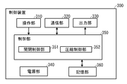
- FIG. 2 is a block diagram showing an electrical configuration of the control device 300.
- the control device 300 is a device that controls each unit of the cooling system 1, is provided in the vicinity of the first cooling system 10, and as illustrated in FIG. 2, the operation unit 310, the communication unit 320, the output unit 330, and the power supply unit 340. , A control unit 350, and a storage unit 360.
- the control device 300 includes the electrical components of the first cooling system 10, the second cooling system 100, and the third cooling system 200 (for example, various open/close valves, various detection units, etc.). Will be described as being electrically connected via wiring (not shown).
- the operation unit 310 is an operation unit for receiving operation inputs regarding various types of information.
- the operation unit 310 is configured using a known operation means such as a touch pad, a remote operation means such as a remote controller, or a hard switch.
- the communication unit 320 is a communication unit for communicating with each electrical unit of the first cooling system 10, the second cooling system 100, and the third cooling system 200, or an external device such as a management server. For example, it is configured using a known communication means or the like.
- the output unit 330 is an output unit that outputs various kinds of information based on the control of the control unit 350, and is a known display unit such as a flat panel display such as a liquid crystal display or an organic EL display, or a known sound output such as a speaker. It is configured using means or the like.
- the power supply unit 340 is a power supply unit that supplies power supplied from a commercial power supply (not shown) or power stored in the power supply unit 340 to each unit of the control device 300.
- the control unit 350 is a control unit that controls each unit of the control device 300.
- the control unit 350 includes a CPU, various programs that are interpreted and executed on the CPU (including a basic control program such as an OS and an application program that is started on the OS and realizes a specific function), and programs.
- a computer configured with an internal memory such as a RAM for storing various data.
- control unit 350 functionally and conceptually includes an opening/closing control unit 351 and a compression control unit 352.
- the opening/closing control unit 351 is an opening/closing control unit that controls the opening/closing of the first opening/closing valve 72a and the second opening/closing valve 72b based on the set temperature of the second refrigerant set by a predetermined method.
- the compression control unit 352 controls the compression unit 20 based on the detection result of the first temperature detection unit 73a or the second temperature detection unit 73b and the temperature of the second refrigerant acquired by a predetermined method. Is. The details of the processing executed by the control unit 350 will be described later.
- the storage unit 360 is a recording unit that records programs and various data necessary for the operation of the control device 300, and is configured using, for example, a hard disk (not shown) as an external recording device. However, in place of or together with the hard disk, a magnetic recording medium such as a magnetic disk, an optical recording medium such as a DVD or a Blu-ray disc, or an electric recording medium such as a Flash ROM, a USB memory, or an SD card is included. Any recording medium can be used.
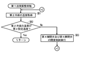
- FIG. 3 is a flowchart of a control process according to the embodiment (steps are abbreviated as “S” in the description of each process below).
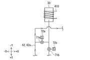
- FIG. 4 is a diagram showing the flow of the first refrigerant accompanying the opening and closing of the first opening/closing valve 72a and the second opening/closing valve 72b.
- FIG. 4A shows the opening of the first opening/closing valve 72a and the closing of the second opening/closing valve 72b.
- the figure which shows the state which carried out, and (b) is a figure which shows the state which closed the 1st on-off valve 72a and opened the 2nd on-off valve 72b.
- the control process is a process for controlling the cooling system 1. Although the timing of executing this control process is arbitrary, the embodiment will be described assuming that the cooling system 1 is started after being turned on.
- the premise of this control processing is as follows in the embodiment. That is, it is assumed that the desired amount of the first refrigerant is contained in the compression unit 20.
- the first open/close valve 72a, the third delivery open/close valve 133c, and the fourth delivery open/close valve 133d are in the closed state, but the other open/close valves are open. It shall be in a state.
- the first refrigerant can circulate in the first circulation flow path 61 and the second circulation flow path 81
- the second refrigerant flows in the delivery flow path 131
- the third refrigerant is the first delivery flow path. 201 and the second delivery flow path 202.
- the control unit 350 of the control device 300 causes the control unit 350 to set the temperature of the first refrigerant (for example, about +80° C. to +90° C. or the like. )” is set.
- the method of setting the set temperature of the first refrigerant is arbitrary, but in the embodiment, the information indicating the set temperature input via the operation unit 310 is set as the set temperature of the first refrigerant to be set. .. However, not limited to this, for example, the information indicating the set temperature stored in advance in the storage unit 360 or the information indicating the set temperature received from the external device via the communication unit 320 is set for the first refrigerant.
- the temperature may be set (the same applies to the method of setting the second set temperature of SA2 described later).
- the control unit 350 of the control device 300 sets the set temperature of the second refrigerant (for example, about ⁇ 20° C. to +80° C., etc., hereinafter referred to as “second set temperature”).
- the compression control unit 352 of the control device 300 controls the compression unit 20 (specifically, controls to repeat the above-described operation cycle). In the embodiment, the process of SA3 is continuously performed until the control process ends.
- control method of the compression unit 20 is arbitrary, but in the embodiment, the detection result of the first temperature detection unit 73a or the second temperature detection unit 73b during the SA3 process and the first transmission during the SA3 process are performed.
- the compression unit 20 (specifically, the operating frequency of the compression unit 20) is controlled based on the detection result of the temperature detection unit 135a or the second delivery temperature detection unit 135b.
- the first temperature detection unit 73a By increasing the operating frequency of the compression unit 20 so that the temperature of the first refrigerant acquired from (or the second temperature detection unit 73b) decreases, the flow rate of the first refrigerant discharged from the compression unit 20 is increased.
- the first temperature detection unit 73a By reducing the operating frequency of the compression unit 20 so that the temperature of the first refrigerant obtained from (or the second temperature detection unit 73b) rises, the flow rate of the first refrigerant discharged from the compression unit 20 is reduced. Accordingly, the compression unit 20 can be controlled based on the temperatures of the first refrigerant and the second refrigerant, and the control of the compression unit 20 can be efficiently performed.
- the opening/closing control unit 351 of the control device 300 controls the opening/closing of the first opening/closing valve 72a and the second opening/closing valve 72b based on the second set temperature set in SA2.
- the opening/closing control method of the first opening/closing valve 72a and the second opening/closing valve 72b is arbitrary, but in the embodiment, the second set temperature is the critical temperature of the first refrigerant (for example, stored in advance in the storage unit 360). If the temperature exceeds the critical temperature of the first refrigerant, the first opening/closing valve 72a is opened and the second opening/closing valve 72b is closed. Along with this, as shown in FIG. 4A, the first refrigerant in the outlet side pipe 62 a flows into the storage part 30. When the second set temperature is lower than the critical temperature of the first refrigerant, the first opening/closing valve 72a is closed and the second opening/closing valve 72b is opened. Along with this, as shown in FIG. 4( b ), the first refrigerant in the storage part 30 flows into the inflow port side pipe 62 b.
- the critical temperature of the first refrigerant for example, stored in advance in the storage unit 360. If the temperature
- the opening/closing control of the first opening/closing valve 72a and the second opening/closing valve 72b based on the second set temperature can effectively perform the inflow/outflow of the first refrigerant in the storage section 30.
- the second set temperature is higher than the critical temperature of the first refrigerant
- the high compression and high density first refrigerant from the outlet side pipe 62a can be flowed into the storage section 30, and the first circulation flow path can be obtained. It is possible to effectively prevent an excessive increase in the pressure of 61 and an excessive increase in the cooling capacity when the second preset temperature is high.
- the first refrigerant in the reservoir 30 can be made to flow into the inlet side pipe 62b, and the refrigerant in the first circulation flow path 61 is correspondingly increased.
- the amount can be increased.
- the first refrigerant is carbon dioxide
- the second refrigerant is the cooling refrigerant for the semiconductor manufacturing system
- the opening/closing control unit 351 of the control device 300 controls opening/closing of the sixth opening/closing valve 72f.
- the process of SA5 is continuously performed until the control process is completed.
- the open/close control method of the sixth open/close valve 72f is arbitrary, but in the embodiment, control is performed based on the second set temperature. For example, when the second set temperature is below the threshold value stored in the storage unit 360 in advance, the sixth opening/closing valve 72f is opened to a predetermined opening. Along with this, the first refrigerant in the portion of the fourth sub pipe 71d upstream of the fifth heat exchange portion 45 flows into the portion of the fourth sub pipe 71d downstream of the fifth heat exchange portion 45. Therefore, heat exchange of the first refrigerant is performed by the fifth heat exchange unit 45. If the second set temperature exceeds the threshold, the sixth open/close valve 72f is closed.
- the first refrigerant in the portion of the fourth sub pipe 71d upstream of the fifth heat exchange portion 45 does not flow into the portion of the fourth sub pipe 71d downstream of the fifth heat exchange portion 45. Therefore, the heat exchange of the first refrigerant by the fifth heat exchange unit 45 is not performed.
- the opening degree of the sixth on-off valve 72f can be adjusted based on the second set temperature, and the temperature of the first refrigerant in the first cooling target side pipe 63a can be efficiently adjusted. Is possible.
- the opening/closing control unit 351 of the control device 300 activates the first temperature adjustment processing (SA6).
- FIG. 5 is a flowchart of the first temperature adjustment processing.
- the first temperature adjustment process is a process for adjusting the temperature of the first refrigerant in the cooling target side pipe 63.
- the opening/closing control unit 351 of the control device 300 changes from the first delivery temperature detection unit 135a (or the second delivery temperature detection unit 135b) to the second delivery temperature detection unit 135a. Get the temperature of the refrigerant.
- the opening/closing control unit 351 of the control device 300 determines whether the temperature of the second refrigerant acquired in SB1 is the second set temperature. Then, the opening/closing control unit 351 of the control device 300 moves to SB3 when the temperature of the second refrigerant is not determined to be the second set temperature (SB2, No), and the temperature of the second refrigerant is When it is determined that the temperature is the second set temperature (SB2, Yes), the first temperature adjustment process is ended and the process returns to the control process of FIG.
- the opening/closing control unit 351 of the control device 300 controls the opening degree of the fourth opening/closing valve 72d and the fifth opening/closing valve 72e based on the temperature of the second refrigerant acquired in SB1. After that, the opening/closing control unit 351 of the control device 300 shifts to SB1 and repeats the processing from SB1 to SB3 until it is determined at SB2 that the temperature of the second refrigerant is the second set temperature.
- the method for controlling the opening degree of the fourth on-off valve 72d and the fifth on-off valve 72e is arbitrary, but for example, the temperature of the second refrigerant acquired at SB1 may be the second set temperature set at SA2.
- the opening degree of the fourth opening/closing valve 72d is made wider than the first reference opening degree
- the opening degree of the fifth opening/closing valve 72e is made narrower than the first reference opening degree.
- the inflow amount of the first refrigerant into the first heat exchange section 41 in the first cooling target side pipe 63a increases, and the inlet of the first refrigerant heat-exchanged by the second heat exchange section 42.
- the opening degree of the fourth opening/closing valve 72d is narrower than the first reference opening degree, and the fifth opening degree is decreased.
- the opening degree of the opening/closing valve 72e is made wider than the first reference opening degree.
- the “first reference opening degree” means, for example, the opening degree of the opening valve when the temperature of the second refrigerant becomes the same as the second set temperature.
- the opening degree of the fourth on-off valve 72d and the fifth on-off valve 72e can be adjusted based on the temperature of the second refrigerant, and the inside of the cooling target side pipe 63 can be adjusted according to the temperature of the second refrigerant.
- the temperature of the first refrigerant can be adjusted efficiently.
- the temperature of the first refrigerant in the cooling target side pipe 63 can be adjusted so that the temperature of the second refrigerant becomes the second set temperature, and the second refrigerant is efficiently cooled. be able to.
- the opening/closing control unit 351 of the control device 300 activates the second temperature adjustment processing (SA7).
- FIG. 6 is a flowchart of the second temperature adjustment processing.
- the second temperature adjustment process is a process for adjusting the temperature of the first refrigerant in the outlet side pipe 62a.
- the opening/closing control unit 351 of the control device 300 causes the first temperature detection unit 73a (or the second temperature detection unit 73b) to remove the first refrigerant. Get the temperature.
- the opening/closing control unit 351 of the control device 300 determines whether the temperature of the first refrigerant acquired in SC1 is lower than the first set temperature. Then, the opening/closing control unit 351 of the control device 300 moves to SC3 when it is not determined that the temperature of the first refrigerant is lower than the first set temperature (SC2, No), and the temperature of the first refrigerant is When it is determined that the temperature is below the first set temperature (SC2, Yes), the second temperature adjustment process is ended and the process returns to the control process of FIG.
- the opening/closing control unit 351 of the control device 300 controls the opening degree of the third opening/closing valve 72c based on the temperature of the first refrigerant acquired in SC1. After that, the opening/closing control unit 351 of the control device 300 shifts to SC1 and repeats the processing from SC1 to SC3 until it is determined at SC2 that the temperature of the first refrigerant is lower than the first set temperature.
- the method for controlling the opening degree of the third opening/closing valve 72c is arbitrary, but, for example, when the temperature of the first refrigerant acquired in SC1 is higher than the first set temperature set in SA1, The opening degree of the 3 on-off valve 72c is made wider than the second reference opening degree. Along with this, the amount of the first refrigerant flowing into the inlet side pipe 62b in the cooling target side pipe 63 increases, so that the temperature of the first refrigerant inside the outlet side pipe 62a can be lowered. In addition, when the temperature of the first refrigerant acquired in SC1 matches the first set temperature set in SA1, the opening degree of the third opening/closing valve 72c is maintained at the second reference opening degree.
- the “second reference opening degree” means, for example, the opening degree of the opening valve when the temperature of the first refrigerant becomes the same as the first set temperature.
- the opening degree of the third on-off valve 72c can be adjusted based on the temperature of the first refrigerant, and the temperature of the first refrigerant in the outlet side pipe 62a can be efficiently adjusted. ..
- the temperature of the first refrigerant in the outlet side pipe 62a can be adjusted so that the temperature of the first refrigerant becomes the first set temperature. Therefore, when the first refrigerant in the outlet side pipe 62a flows into the reservoir 30 via the first sub-pipe 71a, the heat of the inflowing first refrigerant causes the temperature in the reservoir 30 to increase. It is easy to maintain the temperature above the critical temperature.
- the control unit 350 of the control device 300 determines whether or not the timing for ending the control processing (hereinafter, referred to as “end timing”) has arrived.
- the method of determining whether or not this end timing has arrived is arbitrary, but for example, determination is made based on whether or not a predetermined operation has been accepted via the operation unit 310, and if the predetermined operation has been accepted, Determines that the end timing has arrived, and determines that the end timing has not arrived when the predetermined operation has not been accepted. Then, when it is determined that the end timing has arrived (SA8, Yes), the control unit 350 of the control device 300 ends the control process. On the other hand, if it is determined that the end timing has not arrived (SA8, No), the process proceeds to SA6, and the process proceeds from SA6 to SA8 until it is determined in SA8 that the end timing has arrived.
- the first sub-pipe 71a is connected to the outlet-side pipe 62a, and the first refrigerant in the outlet-side pipe 62a is stored in the storage portion 30 via the first sub-pipe 71a.
- the first refrigerant in the reservoir 30 is introduced into the inlet side via the second sub-pipe 71b. Since the second sub-pipe 71b for flowing into the pipe 62b is provided, by the heat of the first refrigerant flowing into the storage unit 30 while suppressing the pressure in the first circulation flow path 61 from becoming excessive.
- the first refrigerant in the first circulation channel 61 is condensed by the first refrigerant condensing in the storage section 30. It is possible to suppress a decrease in the amount of one refrigerant.
- the first sub-pipe 71a is connected to the outlet side pipe 62a, it is possible to store a high-compression/high-density refrigerant as compared with the case where the first sub-pipe 71a is connected to the inlet side pipe 62b.
- the first refrigerant in the storage unit 30 can be caused to flow into the inlet side pipe 62b, and the heat of the first refrigerant that has flowed in can raise the temperature inside the inlet side pipe 62b. It is possible to suppress the functional deterioration or failure of the compression unit 20 due to the saturated steam flowing into.
- a first opening/closing valve 72a capable of switching whether or not to flow the first refrigerant in the outlet side pipe 62a into the storage part 30 and the first refrigerant in the storage part 30 flow into the inlet side pipe 62b.
- a second opening/closing valve 72b capable of switching whether or not to open/close, and an opening/closing controller 351 that controls opening/closing of the first opening/closing valve 72a and the second opening/closing valve 72b based on a second set temperature set by a predetermined method Since it is provided, the opening and closing control of the first opening/closing valve 72a and the second opening/closing valve 72b based on the second set temperature can effectively perform the inflow/outflow of the first refrigerant in the storage section 30.
- the function of the compression unit 20, the function of the storage unit 30, and the function of the first circulation flow path 61 are compared to those of the conventional technology (technology of simply causing the refrigerant in the low-temperature refrigeration cycle to flow into the expansion tank). Since it becomes easier to maintain, it becomes possible to maintain the usability of the refrigerant control system (or the cooling system 1).
- the opening/closing control unit 351 opens the first opening/closing valve 72a and closes the second opening/closing valve 72b so that the second set temperature becomes
- the first opening/closing valve 72a is closed and the second opening/closing valve 72b is opened. Therefore, when the second set temperature is higher than the critical temperature of the first refrigerant, the outlet port is opened.
- the high-compression high-density first refrigerant from the side pipe 62a can be made to flow into the storage portion 30, and the pressure inside the first circulation flow path 61 becomes excessive and excessive when the second set temperature is high.
- the increase in cooling capacity can be prevented more effectively.
- the first refrigerant in the reservoir 30 can be made to flow into the inlet side pipe 62b, and the refrigerant in the first circulation flow path 61 is correspondingly increased.
- the amount can be increased. As a result, it is possible to recover the pressure in the first circulation flow channel 61 that has decreased with the decrease in the second set temperature, and it becomes easier to maintain the function of the first circulation flow channel 61.
- the first refrigerant is carbon dioxide, it is possible to avoid the pressure in the first circulation flow path 61 from becoming excessive even if it expands more easily than the CFC gas.
- the second refrigerant is the cooling refrigerant for the semiconductor manufacturing system, it is possible to avoid the pressure in the first circulation flow path 61 from becoming excessively large even if the temperature range of the second refrigerant is relatively wide. It is possible to suppress a decrease in the flow rate of the first refrigerant in the first circulation flow channel 61 due to the first refrigerant condensing in the storage unit 30.
- the heat exchange means includes a first heat exchange section 41 capable of cooling the second refrigerant, and a second heat exchange section 42 capable of heating the second refrigerant cooled by the first heat exchange section 41.
- the cooling target side pipe 63 includes a first cooling target side pipe 63a located on the first heat exchange unit 41 side and a second cooling target side pipe 63b located on the second heat exchange unit 42 side, and A portion of the cooling target side pipe 63a on the upstream side of the first heat exchange section 41, a third sub-pipe 71c connected to the inlet side pipe 62b, and a first refrigerant in the cooling target side pipe 63 are inlets.
- the third opening/closing valve 72c capable of adjusting the amount of flow into the side pipe 62b is provided, and the opening/closing control unit 351 sets the Since the opening degree of the third opening/closing valve 72c is controlled, the opening degree of the third opening/closing valve 72c can be adjusted based on the temperature of the first refrigerant, and the temperature of the first refrigerant in the outlet side pipe 62a can be efficiently adjusted. Can be adjusted to.
- the fourth on-off valve 72d capable of adjusting the amount of the first refrigerant in the first cooling target side pipe 63a flowing into the first heat exchange section 41, and the first refrigerant heat-exchanged by the second heat exchange section 42.
- a fifth opening/closing valve 72e capable of adjusting the amount of flowing into the inlet side pipe 62b, and the opening/closing control unit 351 sets the fourth opening/closing valve 72d based on the temperature of the second refrigerant acquired by a predetermined method.
- the opening degree of the fifth opening/closing valve 72e is controlled, the temperature of the first refrigerant in the cooling target side pipe 63 can be adjusted so that the temperature of the second refrigerant becomes the second set temperature, and the cooling of the second refrigerant is performed. It can be done efficiently.
- the first refrigerant in the portion of the first cooling target side pipe 63a upstream of the first heat exchange section 41 and the portion of the second cooling target side pipe 63b in the downstream side of the second heat exchange section 42 since the sixth heat exchange unit 46 for performing heat exchange with the first refrigerant is provided, the temperature of the first coolant in the portion of the second cooling target side pipe 63b on the downstream side of the second heat exchange unit 42. Therefore, the dry first refrigerant can be made to flow into the compression unit 20.
- the compression control unit 352 that controls the compression unit 20 based on the detection result of the first temperature detection unit 73a (or the second temperature detection unit 73b) and the temperature of the second refrigerant acquired by the predetermined method. Since it is provided, the compression unit 20 can be controlled based on the temperature of the first refrigerant and the temperature of the second refrigerant, and the control of the compression unit 20 can be efficiently performed.
- each of the above-mentioned electrical components is functionally conceptual, and does not necessarily have to be physically configured as illustrated. That is, the specific form of distribution and integration of each unit is not limited to that shown in the figure, and all or a part of them may be functionally or physically distributed or integrated in arbitrary units according to various loads and usage conditions. Can be configured.
- the “system” in the present application is not limited to a system configured by a plurality of devices, and includes a system configured by a single device.
- the “device” in the present application is not limited to a device configured by a single device, and includes a device configured by a plurality of devices. Further, the data structure of each information described in the above embodiments may be arbitrarily changed.
- control device 300 is configured by being distributed to a plurality of devices that are configured to be able to communicate with each other, the control unit 350 is provided in a part of the plurality of devices, and the other part of the plurality of devices is provided.
- the storage unit 360 may be provided.
- FIG. 7 is a diagram showing a modified example of the cooling system 1.
- the third refrigerant may be air.
- the third cooling system 200 includes a first delivery unit 401 (for example, a known blower) that delivers the third refrigerant to the third heat exchange unit 43, and a fourth delivery unit 401.
- the heat exchange unit 44 may be provided with a second delivery unit 402 that delivers the third refrigerant (for example, a well-known blower).
- the present invention is not limited to this, and for example, the fifth heat exchange unit may be used. At least one of the exchange unit 45, the sixth heat exchange unit 46, and the removal unit 47 may be omitted.
- the fifth heat exchange unit 45 is omitted, the fourth sub pipe 71d and the sixth opening/closing valve 72f can be omitted.
- the first cooling system 10 is described as including the third opening/closing valve 72c, the fourth opening/closing valve 72d, the fifth opening/closing valve 72e, and the sixth opening/closing valve 72f.
- the third opening/closing valve 72c, the fourth opening/closing valve 72d, the fifth opening/closing valve 72e, and the sixth opening/closing valve 72f may be omitted.
- the control process SA7 can be omitted.
- the fourth opening/closing valve 72d and the fifth opening/closing valve 72e are omitted
- the processing of SA6 of the control processing can be omitted.
- the sixth on-off valve 72f is omitted, the control process SA5 can be omitted.
- the first cooling system 10 includes the compression unit 20, the storage unit 30, the first heat exchange unit 41 to the sixth heat exchange unit 46, the removal unit 47, and the circulation unit 50.
- a temperature adjusting unit 410 may be provided in addition to these constituent elements. 8 and 9 are views showing the installation status of the temperature adjusting unit 410.
- the temperature adjusting unit 410 is a temperature adjusting unit for adjusting the temperature of the first refrigerant in the storage unit 30, and is, for example, a known temperature adjuster (for example, at least one of a heating function and a cooling function). And the like, and is installed in the storage unit 30.
- the method of installing the temperature adjusting unit 410 is arbitrary, but it may be installed in the storage unit 30 as shown in FIG. 8, for example. Alternatively, as shown in FIG. 9, it may be installed outside the storage unit 30 so as to be wound around the storage unit 30. With such a temperature adjusting unit 410, the temperature of the refrigerant in the storage unit 30 can be adjusted, and for example, it is possible to prevent the amount of the refrigerant in the first circulation flow channel 61 from decreasing due to the condensation of the refrigerant in the storage unit 30. Easier to do.
- outlet-side piping 62a may not be housed (that is, the entire outlet side pipe 62a may be installed outside the storage part 30 at a position away from the storage part 30 as shown in FIGS. 8 and 9). Well, or may be installed outside the reservoir 30 so as to be wound around the reservoir 30).
- the compression unit 20 is described as a frequency control operation type compressor, but the present invention is not limited to this, and may be, for example, a constant speed operation type compressor.
- FIG. 10 is a diagram showing a modified example of the cooling system 1.
- the compression unit 20 may be a single-stage compressor.
- the cooling system 1 is different from the cooling system 1 of FIG. 1 in that the fourth heat exchange section 44, the second circulation section 80, the second delivery flow path 202, and the second The delivery on-off valve 204 can be omitted.
- the second cooling system 100 includes the air vent unit 110, the storage unit 120, the first sub delivery pipe 132a to the fourth sub delivery pipe 132d, the first delivery on-off valve 133a to the fourth delivery on-off valve 133d, and the pump.
- the present invention is not limited to this, and for example, the air vent unit 110, Storage section 120, first sub-delivery piping 132a to fourth sub-delivery piping 132d, first delivery on-off valve 133a to fourth delivery on-off valve 133d, pump section 134, first delivery temperature detecting section 135a, second delivery temperature detecting section At least one of 135b, the delivery pressure detection unit 136, or the flow rate detection unit 137 may be omitted.
- the third cooling system 200 is described as including the first delivery on-off valve 203, the second delivery on-off valve 204, and the delivery temperature detection unit 205 in the above embodiment, the present invention is not limited to this, and, for example, At least one of the first delivery on-off valve 203, the second delivery on-off valve 204, and the delivery temperature detection unit 205 may be omitted.
- the present invention is not limited to this.
- the operating pressure value of the compression unit 20 obtained by a predetermined method exceeds a threshold value, or the second set temperature is the critical temperature of the first refrigerant.
- the first opening/closing valve 72a When the operating pressure value of the compression unit 20 is below the threshold value or the second set temperature is equal to or higher than the threshold value, the first opening/closing valve 72a is opened and the second opening/closing valve 72b is closed in at least either case.
- the first opening/closing valve 72a may be closed and the second opening/closing valve 72b may be opened in at least one of the cases where the temperature is below the critical temperature of one refrigerant. Accordingly, the opening/closing control of the first opening/closing valve 72a and the second opening/closing valve 72b based on the second set temperature and the operating pressure value of the compression unit 20 can be performed, and the first opening/closing valve based only on the second set temperature.
- the heat of the first refrigerant flowing into the storage unit 30 causes the storage It becomes easy to maintain the temperature in 30 above the critical temperature of the first refrigerant (or the superheated steam temperature).
- the refrigerant control system of Appendix 1 is a circulation flow path connected to a compression unit, and a circulation flow for circulating the refrigerant so that heat exchange between the refrigerant compressed by the compression unit and a cooling target is possible.
- a refrigerant control system for controlling the refrigerant flowing in a passage which is a storage means for storing the refrigerant, and an outlet side pipe constituting the circulation flow path, which is located on the outlet side of the compression means.
- a first pipe for connecting the refrigerant in the outlet side pipe to the storing means via the first pipe, and the circulation flow path.
- An opening/closing control unit that controls opening/closing of the first opening/closing valve and the second opening/closing valve based on the set temperature of the cooling target set by a predetermined method.
- the refrigerant control system according to attachment 2 is the refrigerant control system according to attachment 1, wherein the opening/closing control means opens the first opening/closing valve when the set temperature of the cooling target exceeds a critical temperature of the refrigerant. At the same time, the second opening/closing valve is closed, and when the preset temperature of the cooling target is lower than the critical temperature of the refrigerant, the first opening/closing valve is closed and the second opening/closing valve is opened.
- the refrigerant control system according to appendix 3 is the refrigerant control system according to appendix 2, wherein the opening/closing control means is configured such that when the operating pressure value of the compression means obtained by a predetermined method exceeds a threshold value, or the set temperature of the cooling target. Is at least one of the cases where it exceeds the critical temperature of the refrigerant, the first opening/closing valve is opened, the second opening/closing valve is closed, and the operating pressure value of the compression means is below a threshold value, or The first opening/closing valve is closed and the second opening/closing valve is opened in at least one of the case where the set temperature of the cooling target is lower than the critical temperature of the refrigerant.
- the refrigerant control system according to appendix 4 is the refrigerant control system according to any one of appendices 1 to 3, further comprising temperature adjusting means for adjusting the temperature of the refrigerant inside the storage means.
- the refrigerant control system according to attachment 5 is the refrigerant control system according to any one of attachments 1 to 4, wherein the refrigerant is carbon dioxide.
- the refrigerant control system according to appendix 6 is the refrigerant control system according to any one of appendices 1 to 5, wherein the cooling target is a cooling refrigerant for a semiconductor manufacturing system.
- a cooling system is a cooling system for cooling the cooling target by using the refrigerant, which is connected to the compression means for compressing the refrigerant and the compression means, and is connected to the cooling target side.
- a circulation flow path having a cooling target side pipe located therein, a circulation flow path for circulating the refrigerant so that heat exchange between the refrigerant compressed by the compression means and the cooling target is possible,
- the refrigerant control system according to any one of claims 1 to 6, and heat exchanging means provided in the cooling target side pipe, wherein heat of the refrigerant and the cooling target in the cooling target side pipe And heat exchange means for performing the exchange.
- the cooling system according to appendix 8 is the cooling system according to appendix 7, wherein the heat exchanging means includes a first heat exchanging means capable of cooling the cooling target and the cooling target cooled by the first heat exchanging means.
- a heatable second heat exchange means wherein the cooling target side pipe is a first cooling target side pipe located on the first heat exchange means side, and a second cooling target side pipe located on the second heat exchange means side.
- a third pipe connected to the inlet side pipe, and a third opening/closing valve provided in the third pipe, wherein the refrigerant in the cooling target side pipe is the inlet side
- a third opening/closing valve capable of adjusting the amount of flow into the pipe, and the opening/closing control unit controls the opening degree of the third opening/closing valve based on the detection result of the detection unit.
- the cooling system according to appendix 9 is the cooling system according to appendix 8, which is a fourth opening/closing valve provided in a portion of the first cooling target side pipe upstream of the first heat exchange unit, A fourth opening/closing valve capable of adjusting the amount of the refrigerant in the cooling target side pipe flowing into the first heat exchanging means, and provided in a portion of the second cooling target side pipe downstream of the second heat exchanging means.
- a fifth on-off valve capable of adjusting the amount of the refrigerant, which has been heat-exchanged by the second heat-exchange means, flowing into the inflow port side pipe, The opening control of the fourth on-off valve and the fifth on-off valve is performed based on the temperature of the cooling target acquired by a predetermined method.
- the cooling system according to supplementary note 10 is the cooling system according to any one of supplementary notes 7 to 9, wherein the refrigerant in a portion of the first cooling target side pipe on the upstream side of the first heat exchange means, and Refrigerant heat exchanging means for exchanging heat with the refrigerant in a portion of the second cooling target side pipe downstream of the second heat exchanging means is provided.
- the cooling system according to supplementary note 11 is the cooling system according to any one of supplementary notes 7 to 10, wherein the compression means is based on a detection result of the detection means and a temperature of the cooling target acquired by a predetermined method.
- a compression control means for controlling the above is provided.
- the refrigerant is the first pipe connected to the outlet side pipe, and the refrigerant in the outlet side pipe is connected via the first pipe.
- the refrigerant in the storage means can be caused to flow into the inlet side pipe, and the temperature of the inside of the inlet side pipe can be raised by the heat of the introduced refrigerant, so that saturated vapor can flow into the compression means.
- a first opening/closing valve capable of switching whether or not the refrigerant in the outlet side pipe flows into the storage means
- a second opening/closing valve capable of switching whether or not the refrigerant in the storage means flows into the inlet side pipe. Since the opening/closing valve and the opening/closing control means for controlling the opening/closing of the first opening/closing valve and the second opening/closing valve based on the set temperature of the cooling target set by the predetermined method are provided, based on the set temperature of the cooling target.
- the refrigerant By controlling the opening/closing of the first opening/closing valve and the second opening/closing valve, the refrigerant can effectively flow in and out of the storage means. From the above, it becomes easier to maintain the function of the compression unit, the function of the storage unit, and the function of the circulation flow path, as compared with the conventional technology (the technology of simply flowing the refrigerant in the low-temperature refrigeration cycle into the expansion tank). The usability of the refrigerant control system (or the cooling system) can be maintained.
- the opening/closing control unit opens the first opening/closing valve and closes the second opening/closing valve when the set temperature of the cooling target is higher than the critical temperature of the refrigerant.
- the first opening/closing valve is closed and the second opening/closing valve is opened. Therefore, when the set temperature of the cooling target is higher than the critical temperature of the refrigerant, Highly compressed and high density refrigerant from the outlet side pipe can flow into the storage means, and excessive cooling capacity increases when the pressure in the circulation channel becomes excessive and the set temperature of the cooling target is high. Can be prevented more effectively.
- the refrigerant in the storage means can be made to flow into the inlet side pipe, and the amount of refrigerant in the circulation flow path can be increased accordingly. As a result, it is possible to recover the pressure in the circulation flow channel that has decreased with the decrease in the set temperature of the cooling target, and it becomes easier to maintain the function of the circulation flow channel.
- the opening/closing control means is at least one of the case where the operating pressure value of the compression means exceeds the threshold value or the set temperature of the cooling target exceeds the critical temperature of the refrigerant. At least one of the case where the first opening/closing valve is opened and the second opening/closing valve is closed, and the operating pressure value of the compression means is below the threshold value, or the set temperature of the cooling target is below the critical temperature of the refrigerant.
- the opening/closing control of the first opening/closing valve and the second opening/closing valve is performed based on the set temperature of the cooling target and the operating pressure value of the compression means.
- the opening/closing control of the first opening/closing valve and the second opening/closing valve based on only the set temperature of the cooling target is performed, the pressure in the circulation passage is suppressed from becoming excessive, and the storage means is provided.
- the heat of the inflowing refrigerant makes it easy to maintain the temperature in the storage means at the critical temperature of the refrigerant or higher (or the superheated steam temperature).
- the temperature adjusting means for adjusting the temperature of the refrigerant in the storage means since the temperature adjusting means for adjusting the temperature of the refrigerant in the storage means is provided, the temperature of the refrigerant in the storage means can be adjusted. Condensation makes it easier to prevent the amount of refrigerant in the circulation passage from decreasing.
- the refrigerant is carbon dioxide, it is possible to prevent the pressure in the circulation passage from becoming excessive even if it expands more easily than CFC gas.
- the cooling target is the cooling refrigerant of the semiconductor manufacturing system
- the pressure in the circulation passage becomes excessively large even if the temperature range of the cooling target is relatively wide. It is possible to prevent the decrease of the flow rate of the refrigerant in the circulation passage due to the condensation of the refrigerant in the storage means.
- the heat exchange means includes a first heat exchange means capable of cooling the cooling target and a second heat exchange means capable of heating the cooling target cooled by the first heat exchange means.
- a cooling target side pipe includes a first cooling target side pipe located on the first heat exchange means side and a second cooling target side pipe located on the second heat exchange means side, and the first cooling It is possible to adjust the amount of the refrigerant in the cooling target side pipe that flows into the inlet side pipe, and the third pipe connected to the upstream side of the first heat exchange means in the target side pipe, the inlet side pipe Since the opening/closing control means controls the opening degree of the third opening/closing valve based on the detection result of the detecting means, the opening degree of the third opening/closing valve is adjusted based on the temperature of the refrigerant. The temperature of the refrigerant in the outlet side pipe can be efficiently adjusted.
- heat exchange is performed by the fourth on-off valve, which is capable of adjusting the amount of the refrigerant in the first cooling target side pipe flowing into the first heat exchange means, and the second heat exchange means.
- a fifth opening/closing valve capable of adjusting the amount of the refrigerant flowing into the inlet side pipe; and the opening/closing control means based on the temperature of the cooling target acquired by a predetermined method, the fourth opening/closing valve and the fifth opening/closing valve. Since the opening degree of the valve is controlled, the temperature of the refrigerant in the cooling target side pipe can be adjusted so that the temperature of the cooling target becomes the set temperature of the cooling target, and the cooling target can be efficiently cooled.
- the refrigerant in the portion of the first cooling target side pipe on the upstream side of the first heat exchange means and the downstream side of the second heat exchange means on the second cooling target side pipe Since it is provided with the refrigerant heat exchange means for exchanging heat with the refrigerant in the portion, it is possible to increase the temperature of the refrigerant in the portion of the second cooling target side pipe on the downstream side of the second heat exchange means. It is possible to allow the dry refrigerant to flow into the compression means.
- the compression control unit that controls the compression unit based on the detection result of the detection unit and the temperature of the cooling target acquired by the predetermined method is provided, the temperature of the refrigerant and The compression means can be controlled based on the temperature of the cooling target, and the compression means can be efficiently controlled.
- Cooling system 10 1st cooling system 20 Compressing part 21 Compressing part main body 22 1st outlet 23 1st inlet 24 2nd outlet 25 2nd inlet 30 Storage part 41 1st heat exchanging part 42 2nd heat exchanging part 43 3rd heat exchange part 44 4th heat exchange part 45 5th heat exchange part 46 6th heat exchange part 47 Removal part 50 Circulation part 60 1st circulation part 61 1st circulation flow path 62 Compression part side piping 62a Outlet side Piping 62b Inlet side piping 63 Cooling target side piping 63a First cooling target side piping 63b Second cooling target side piping 71a First sub piping 71b Second sub piping 71c Third sub piping 71d Fourth sub piping 72a First opening/closing valve 72b 2nd on-off valve 72c 3rd on-off valve 72d 4th on-off valve 72e 5th on-off valve 72f 6 on-off valve 73a 1st temperature detection part 73b
Landscapes
- Engineering & Computer Science (AREA)
- Physics & Mathematics (AREA)
- Mechanical Engineering (AREA)
- Thermal Sciences (AREA)
- General Engineering & Computer Science (AREA)
- Chemical & Material Sciences (AREA)
- Chemical Kinetics & Catalysis (AREA)
- Analytical Chemistry (AREA)
- Power Engineering (AREA)
- Devices That Are Associated With Refrigeration Equipment (AREA)
- Cooling Or The Like Of Electrical Apparatus (AREA)
Abstract
Priority Applications (8)
| Application Number | Priority Date | Filing Date | Title |
|---|---|---|---|
| JP2021501388A JP6980945B2 (ja) | 2019-02-25 | 2019-02-25 | 冷媒制御システム、及び冷却システム |
| KR1020217016572A KR102700265B1 (ko) | 2019-02-25 | 2019-02-25 | 냉매 제어 시스템 및 냉각 시스템 |
| CN201980079308.0A CN113167507B (zh) | 2019-02-25 | 2019-02-25 | 制冷控制系统和冷却系统 |
| EP19917499.6A EP3933297B1 (fr) | 2019-02-25 | 2019-02-25 | Système de refroidissement avec un système de régulation de fluide frigorigène |
| PCT/JP2019/007047 WO2020174530A1 (fr) | 2019-02-25 | 2019-02-25 | Système de régulation de fluide frigorigène et système de refroidissement |
| SG11202104998WA SG11202104998WA (en) | 2019-02-25 | 2019-02-25 | Refrigerant control system and cooling system |
| TW109103578A TWI797419B (zh) | 2019-02-25 | 2020-02-05 | 製冷控制系統和冷卻系統 |
| US17/347,368 US11841177B2 (en) | 2019-02-25 | 2021-06-14 | Refrigerant control system and cooling system |
Applications Claiming Priority (1)
| Application Number | Priority Date | Filing Date | Title |
|---|---|---|---|
| PCT/JP2019/007047 WO2020174530A1 (fr) | 2019-02-25 | 2019-02-25 | Système de régulation de fluide frigorigène et système de refroidissement |
Related Child Applications (1)
| Application Number | Title | Priority Date | Filing Date |
|---|---|---|---|
| US17/347,368 Continuation-In-Part US11841177B2 (en) | 2019-02-25 | 2021-06-14 | Refrigerant control system and cooling system |
Publications (1)
| Publication Number | Publication Date |
|---|---|
| WO2020174530A1 true WO2020174530A1 (fr) | 2020-09-03 |
Family
ID=72238861
Family Applications (1)
| Application Number | Title | Priority Date | Filing Date |
|---|---|---|---|
| PCT/JP2019/007047 Ceased WO2020174530A1 (fr) | 2019-02-25 | 2019-02-25 | Système de régulation de fluide frigorigène et système de refroidissement |
Country Status (8)
| Country | Link |
|---|---|
| US (1) | US11841177B2 (fr) |
| EP (1) | EP3933297B1 (fr) |
| JP (1) | JP6980945B2 (fr) |
| KR (1) | KR102700265B1 (fr) |
| CN (1) | CN113167507B (fr) |
| SG (1) | SG11202104998WA (fr) |
| TW (1) | TWI797419B (fr) |
| WO (1) | WO2020174530A1 (fr) |
Cited By (3)
| Publication number | Priority date | Publication date | Assignee | Title |
|---|---|---|---|---|
| CN112856841A (zh) * | 2021-02-07 | 2021-05-28 | 爱美达(上海)热能系统有限公司 | 温控设备 |
| CN113932504A (zh) * | 2021-12-21 | 2022-01-14 | 中国飞机强度研究所 | 一种飞机测试充注系统及充注方法 |
| CN115046323A (zh) * | 2022-06-30 | 2022-09-13 | 珠海格力电器股份有限公司 | 制冷调节系统、制冷系统、电器及制冷方法 |
Families Citing this family (1)
| Publication number | Priority date | Publication date | Assignee | Title |
|---|---|---|---|---|
| KR102439282B1 (ko) * | 2020-12-29 | 2022-09-05 | 엠에이치기술개발 주식회사 | 복수의 냉각 유닛을 구비한 냉각 시스템 |
Citations (9)
| Publication number | Priority date | Publication date | Assignee | Title |
|---|---|---|---|---|
| JPS5051250U (fr) * | 1973-09-08 | 1975-05-19 | ||
| JPS60264A (ja) * | 1983-06-16 | 1985-01-05 | 新明和工業株式会社 | 低温冷凍装置 |
| JPS6438567A (en) * | 1987-07-31 | 1989-02-08 | Matsushita Electric Industrial Co Ltd | Refrigeration cycle device |
| JPS6438568A (en) * | 1987-07-31 | 1989-02-08 | Matsushita Electric Industrial Co Ltd | Heat pump device |
| JPH1137579A (ja) * | 1997-07-11 | 1999-02-12 | Zexel Corp | 冷凍装置 |
| JP2000146328A (ja) * | 1998-11-16 | 2000-05-26 | Sanyo Electric Co Ltd | 冷凍空調装置 |
| JP2001141316A (ja) * | 1999-11-17 | 2001-05-25 | Sanden Corp | Co2冷凍回路の制御機構 |
| JP2002195705A (ja) * | 2000-12-28 | 2002-07-10 | Tgk Co Ltd | 超臨界冷凍サイクル |
| WO2014181399A1 (fr) | 2013-05-08 | 2014-11-13 | 三菱電機株式会社 | Dispositif de réfrigération binaire |
Family Cites Families (26)
| Publication number | Priority date | Publication date | Assignee | Title |
|---|---|---|---|---|
| KR930000852B1 (ko) | 1987-07-31 | 1993-02-06 | 마쓰시다덴기산교 가부시기가이샤 | 히이트 펌프장치 |
| JP2613404B2 (ja) | 1987-11-24 | 1997-05-28 | 株式会社東芝 | 絶縁母線の接続方法 |
| JPH01273959A (ja) * | 1988-04-25 | 1989-11-01 | Nippon Denso Co Ltd | 車両用空気調和機 |
| JPH0551250A (ja) | 1991-08-21 | 1993-03-02 | Isuzu Motors Ltd | 低熱膨張セラミツク材料及びその製造法 |
| JPH06264A (ja) | 1992-06-22 | 1994-01-11 | Brother Ind Ltd | ミシン |
| JP3155653B2 (ja) * | 1993-09-29 | 2001-04-16 | 東芝キヤリア株式会社 | 混合冷媒を用いた冷凍装置 |
| JP3091682B2 (ja) * | 1996-01-26 | 2000-09-25 | 三洋電機株式会社 | エンジン駆動ヒートポンプ装置 |
| JPH1163686A (ja) * | 1997-08-12 | 1999-03-05 | Zexel Corp | 冷却サイクル |
| JP2000028237A (ja) * | 1998-07-14 | 2000-01-28 | Matsushita Electric Ind Co Ltd | 分離型冷凍サイクル装置 |
| JP2000266415A (ja) * | 1999-03-15 | 2000-09-29 | Bosch Automotive Systems Corp | 冷凍サイクル |
| JP2002081777A (ja) * | 2000-09-08 | 2002-03-22 | Hitachi Ltd | 冷凍サイクル |
| DE10124227C5 (de) * | 2001-05-18 | 2007-08-30 | Air Liquide Deutschland Gmbh | Vorrichtung zum Kühlen mittels adiabatischer Entspannung eines Gases oder Gasgemisches |
| JP4862198B2 (ja) * | 2006-04-11 | 2012-01-25 | 株式会社前川製作所 | Co2冷媒を用いた給湯装置及びその運転方法 |
| EP2147264B1 (fr) * | 2007-04-24 | 2019-01-16 | Carrier Corporation | Système de compression de vapeur de réfrigérant |
| US20110041523A1 (en) * | 2008-05-14 | 2011-02-24 | Carrier Corporation | Charge management in refrigerant vapor compression systems |
| WO2011064813A1 (fr) * | 2009-11-25 | 2011-06-03 | 三菱電機株式会社 | Accumulateur et dispositif de cycle de réfrigération |
| CN102022853A (zh) * | 2010-11-18 | 2011-04-20 | 海尔集团公司 | 空调器系统 |
| JP6148001B2 (ja) * | 2012-12-14 | 2017-06-14 | シャープ株式会社 | 空気調和機 |
| JP6087611B2 (ja) * | 2012-12-14 | 2017-03-01 | シャープ株式会社 | 冷凍サイクル及びこれを備えた空気調和機 |
| CN104132486B (zh) * | 2014-07-11 | 2016-04-27 | 浙江大学 | 一种无泵式热喷射制冷循环方法和装置 |
| WO2017061009A1 (fr) * | 2015-10-08 | 2017-04-13 | 三菱電機株式会社 | Dispositif à cycle frigorifique |
| CA2958388A1 (fr) * | 2016-04-27 | 2017-10-27 | Rolls-Royce Corporation | Entreposage transitoire supercritique de refrigerant |
| JP6683076B2 (ja) * | 2016-09-02 | 2020-04-15 | 株式会社デンソー | 冷凍サイクル装置 |
| JP6857883B2 (ja) * | 2017-03-31 | 2021-04-14 | 三菱重工サーマルシステムズ株式会社 | 地中熱利用システム及び地中熱利用方法 |
| CN109114718A (zh) * | 2018-09-27 | 2019-01-01 | 克莱门特捷联制冷设备(上海)有限公司 | 机房用复合型空调系统及其控制方法 |
| US11421923B2 (en) * | 2019-05-22 | 2022-08-23 | Johnson Controls Tyco IP Holdings LLP | Systems and methods for reheat control of an HVAC system |
-
2019
- 2019-02-25 KR KR1020217016572A patent/KR102700265B1/ko active Active
- 2019-02-25 CN CN201980079308.0A patent/CN113167507B/zh active Active
- 2019-02-25 WO PCT/JP2019/007047 patent/WO2020174530A1/fr not_active Ceased
- 2019-02-25 EP EP19917499.6A patent/EP3933297B1/fr active Active
- 2019-02-25 SG SG11202104998WA patent/SG11202104998WA/en unknown
- 2019-02-25 JP JP2021501388A patent/JP6980945B2/ja active Active
-
2020
- 2020-02-05 TW TW109103578A patent/TWI797419B/zh active
-
2021
- 2021-06-14 US US17/347,368 patent/US11841177B2/en active Active
Patent Citations (9)
| Publication number | Priority date | Publication date | Assignee | Title |
|---|---|---|---|---|
| JPS5051250U (fr) * | 1973-09-08 | 1975-05-19 | ||
| JPS60264A (ja) * | 1983-06-16 | 1985-01-05 | 新明和工業株式会社 | 低温冷凍装置 |
| JPS6438567A (en) * | 1987-07-31 | 1989-02-08 | Matsushita Electric Industrial Co Ltd | Refrigeration cycle device |
| JPS6438568A (en) * | 1987-07-31 | 1989-02-08 | Matsushita Electric Industrial Co Ltd | Heat pump device |
| JPH1137579A (ja) * | 1997-07-11 | 1999-02-12 | Zexel Corp | 冷凍装置 |
| JP2000146328A (ja) * | 1998-11-16 | 2000-05-26 | Sanyo Electric Co Ltd | 冷凍空調装置 |
| JP2001141316A (ja) * | 1999-11-17 | 2001-05-25 | Sanden Corp | Co2冷凍回路の制御機構 |
| JP2002195705A (ja) * | 2000-12-28 | 2002-07-10 | Tgk Co Ltd | 超臨界冷凍サイクル |
| WO2014181399A1 (fr) | 2013-05-08 | 2014-11-13 | 三菱電機株式会社 | Dispositif de réfrigération binaire |
Cited By (5)
| Publication number | Priority date | Publication date | Assignee | Title |
|---|---|---|---|---|
| CN112856841A (zh) * | 2021-02-07 | 2021-05-28 | 爱美达(上海)热能系统有限公司 | 温控设备 |
| CN113932504A (zh) * | 2021-12-21 | 2022-01-14 | 中国飞机强度研究所 | 一种飞机测试充注系统及充注方法 |
| CN113932504B (zh) * | 2021-12-21 | 2022-03-01 | 中国飞机强度研究所 | 一种飞机测试充注系统及充注方法 |
| CN115046323A (zh) * | 2022-06-30 | 2022-09-13 | 珠海格力电器股份有限公司 | 制冷调节系统、制冷系统、电器及制冷方法 |
| CN115046323B (zh) * | 2022-06-30 | 2023-05-12 | 珠海格力电器股份有限公司 | 制冷调节系统、制冷系统、电器及制冷方法 |
Also Published As
| Publication number | Publication date |
|---|---|
| CN113167507A (zh) | 2021-07-23 |
| KR20210130700A (ko) | 2021-11-01 |
| TWI797419B (zh) | 2023-04-01 |
| JPWO2020174530A1 (ja) | 2021-09-30 |
| EP3933297B1 (fr) | 2023-11-08 |
| US20210302087A1 (en) | 2021-09-30 |
| CN113167507B (zh) | 2023-03-31 |
| JP6980945B2 (ja) | 2021-12-15 |
| KR102700265B1 (ko) | 2024-08-28 |
| EP3933297A4 (fr) | 2022-10-05 |
| US11841177B2 (en) | 2023-12-12 |
| EP3933297A1 (fr) | 2022-01-05 |
| TW202032069A (zh) | 2020-09-01 |
| SG11202104998WA (en) | 2021-09-29 |
Similar Documents
| Publication | Publication Date | Title |
|---|---|---|
| JP4517529B2 (ja) | ヒートポンプサイクル、加熱装置、車両用暖房装置、暖房装置および蒸気圧縮式冷凍サイクル | |
| CN102803869B (zh) | 用于带高效率冷凝器的冷却系统的低环境运行程序 | |
| WO2020174530A1 (fr) | Système de régulation de fluide frigorigène et système de refroidissement | |
| JP5983451B2 (ja) | 暖房システム | |
| JP5205079B2 (ja) | ヒートポンプ式給湯暖房装置 | |
| CN101240927B (zh) | 水源空调系统及其控制方法 | |
| JP6577264B2 (ja) | 空調調和機 | |
| JP4947558B2 (ja) | ラック冷却システム | |
| JP2008267700A (ja) | 冷却加熱装置 | |
| JP6817735B2 (ja) | ヒートポンプ式空調システム | |
| JP2010060181A (ja) | 冷凍装置 | |
| JP6861821B2 (ja) | 冷凍サイクル装置 | |
| WO2021240729A1 (fr) | Dispositif à cycle de réfrigération | |
| JP6887068B1 (ja) | 冷媒制御システム、及び冷却システム | |
| JP2011012844A (ja) | 冷凍サイクル装置 | |
| JPWO2016166873A1 (ja) | ヒートポンプシステム | |
| JP7179068B2 (ja) | 熱源システム | |
| JP4765727B2 (ja) | 冷凍装置 | |
| JP2011075185A (ja) | 恒温庫 | |
| JP4082389B2 (ja) | ヒートポンプ給湯装置 | |
| JP5481824B2 (ja) | 自動販売機 | |
| JP2011185577A (ja) | 温度調整送風装置 |
Legal Events
| Date | Code | Title | Description |
|---|---|---|---|
| 121 | Ep: the epo has been informed by wipo that ep was designated in this application |
Ref document number: 19917499 Country of ref document: EP Kind code of ref document: A1 |
|
| ENP | Entry into the national phase |
Ref document number: 2021501388 Country of ref document: JP Kind code of ref document: A |
|
| NENP | Non-entry into the national phase |
Ref country code: DE |
|
| ENP | Entry into the national phase |
Ref document number: 2019917499 Country of ref document: EP Effective date: 20210927 |
|
| WWG | Wipo information: grant in national office |
Ref document number: 11202104998W Country of ref document: SG |
|
| WWP | Wipo information: published in national office |
Ref document number: 11202104998W Country of ref document: SG |