WO2020174561A1 - 内視鏡用対物光学系 - Google Patents
内視鏡用対物光学系 Download PDFInfo
- Publication number
- WO2020174561A1 WO2020174561A1 PCT/JP2019/007205 JP2019007205W WO2020174561A1 WO 2020174561 A1 WO2020174561 A1 WO 2020174561A1 JP 2019007205 W JP2019007205 W JP 2019007205W WO 2020174561 A1 WO2020174561 A1 WO 2020174561A1
- Authority
- WO
- WIPO (PCT)
- Prior art keywords
- lens
- observation state
- optical system
- objective optical
- lens group
- Prior art date
- Legal status (The legal status is an assumption and is not a legal conclusion. Google has not performed a legal analysis and makes no representation as to the accuracy of the status listed.)
- Ceased
Links
Images









Classifications
-
- G—PHYSICS
- G02—OPTICS
- G02B—OPTICAL ELEMENTS, SYSTEMS OR APPARATUS
- G02B13/00—Optical objectives specially designed for the purposes specified below
- G02B13/04—Reversed telephoto objectives
Definitions
- the present invention relates to an objective optical system.
- the present invention relates to an objective optical system (imaging optical system) for an endoscope, and can be used for an endoscope device used in, for example, the medical field or industrial field.
- the endoscope is a device widely used in the medical field and the industrial field. Particularly in the medical field, from the viewpoint of reducing the burden on patients and improving the diagnostic accuracy, downsizing and high pixel number of imaging devices of endoscopes, such as CCDs and CMOSs, have been advanced.
- the endoscope objective optical system is also required to have a wide observation depth from the far point to the near point while satisfying optical performance such as widening of the angle and correction of aberrations.
- the F number (Fno) of the objective optical system is preferably in the following range so as not to be affected by light diffraction. Fno ⁇ 2 ⁇ P/1.22/ ⁇
- P is the pixel pitch of the image sensor.
- the optical performance will deteriorate due to diffraction. Therefore, by reducing the F number of the optical system, it is possible to avoid the influence of diffraction. However, if the F number of the optical system is reduced, the observation depth becomes shallow.
- each component is fixed by a mechanical member. At this time, it is necessary to fix the mechanical member with an adhesive.
- the above-mentioned endoscope objective optical system may not be applicable to observation due to the influence of diffraction caused by miniaturization and the deterioration of optical performance due to manufacturing variations.
- the zoom objective optical systems of Patent Documents 1 and 2 are small in size, but have optical specifications with a large F number. For this reason, in a recent situation where the pixel pitch is small due to the downsizing of the image sensor and the increase in the number of pixels, the optical performance is deteriorated due to the influence of diffraction. Further, the zoom objective optical systems of Patent Documents 1 and 2 cannot be applied to good observation because the problem of manufacturing variations is not taken into consideration.
- the present invention has been made in view of such problems, and it is possible to perform magnifying observation (near-point observation) according to a change in the object distance, and it is possible to secure a sufficient observation depth with a small size and a wide-angle visual field. It is an object of the present invention to provide a high-performance objective optical system for an endoscope, which has a corner, and in which the optical aberration is well corrected from the center of the screen to the peripheral portion, and the observation and diagnosis of the lesion are easy.
- an objective optical system for an endoscope includes a positive first lens group and a negative first lens group in order from the object side.
- the first lens group is composed of only two lens groups and a positive third lens group, and the first lens group comprises, in order from the object side, a first lens composed of a negative single lens and a second lens composed of a negative single lens.
- the second lens group performs focusing and zooming by moving on the optical axis
- the third lens group includes a cemented lens and an image sensor or a cover glass formed on the image sensor. And a positive single lens that is cemented.
- the magnified observation state will be referred to as the "near-point observation state”.
- the normal observation state is appropriately referred to as “at the time of focusing on a long-distance object point”.
- magied observation near point observation
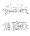
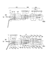
- FIG. 3A is a lens cross-sectional view of the endoscope objective optical system according to the embodiment in a normal observation state.
- FIG. 3B is a lens cross-sectional view of the endoscope objective optical system according to the embodiment in a magnified observation state.
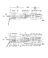
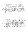
- 3A is a lens cross-sectional view of an endoscope objective optical system according to Example 1 in a normal observation state.
- FIG. 3B is a lens cross-sectional view of the endoscope objective optical system according to Example 1 in a magnified observation state.
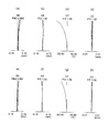
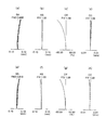
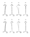
- (a) is a spherical aberration (SA) in a normal observation state
- (b) is an astigmatism (AS) in a normal observation state
- (c) is a normal observation state.
- Distortion aberrations (DT) and (d) in FIG. 3 indicate lateral chromatic aberration (CC) in a normal observation state.
- (e) is spherical aberration (SA) in the magnified observation state
- (f) is astigmatism (AS) in the magnified observation state
- (g) is distortion aberration (DT) in the magnified observation state
- (h) is magnified.
- the chromatic aberration of magnification (CC) in the observation state is shown.
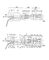
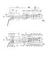
- FIG. 7A is a lens cross-sectional view of an endoscope objective optical system according to Example 2 in a normal observation state.
- FIG. 6B is a lens cross-sectional view of the endoscope objective optical system according to Example 2 in a magnified observation state.
- SA spherical aberration
- AS astigmatism
- DT Distortion aberrations
- DT lateral chromatic aberration
- CC lateral chromatic aberration
- SA spherical aberration
- AS astigmatism
- DT distortion aberration
- CC chromatic aberration of magnification
- a is a spherical aberration (SA) in a normal observation state
- (b) is an astigmatism (AS) in a normal observation state
- (c) is a normal observation state.
- Distortion aberrations (DT) and (d) in FIG. 3 indicate lateral chromatic aberration (CC) in a normal observation state.
- (e) is spherical aberration (SA) in the magnified observation state
- (f) is astigmatism (AS) in the magnified observation state
- g) is distortion aberration (DT) in the magnified observation state
- (h) is magnified.
- the chromatic aberration of magnification (CC) in the observation state is shown.
- FIG. 7A is a lens cross-sectional view of an endoscope objective optical system according to Example 4 in a normal observation state.
- FIG. 7B is a lens cross-sectional view of the endoscope objective optical system according to Example 4 in a magnified observation state.
- SA spherical aberration
- AS astigmatism
- DT Distortion aberrations
- DT lateral chromatic aberration
- SA spherical aberration
- AS astigmatism
- DT distortion aberration
- CC chromatic aberration of magnification
- a is a spherical aberration (SA) in a normal observation state
- (b) is an astigmatism (AS) in a normal observation state
- (c) is a normal observation state.
- Distortion aberrations (DT) and (d) in FIG. 3 indicate lateral chromatic aberration (CC) in a normal observation state.
- (e) is spherical aberration (SA) in the magnified observation state
- (f) is astigmatism (AS) in the magnified observation state
- g) is distortion aberration (DT) in the magnified observation state
- (h) is magnified.
- the chromatic aberration of magnification (CC) in the observation state is shown.
- FIG. 16A is a lens cross-sectional view of an endoscope objective optical system according to Example 6 in a normal observation state.
- FIG. FIG. 7B is a lens cross-sectional view of the endoscope objective optical system according to Example 6 in a magnified observation state.
- SA spherical aberration
- AS astigmatism
- DT Distortion aberrations
- DT lateral chromatic aberration
- CC lateral chromatic aberration
- SA spherical aberration
- AS astigmatism
- DT distortion aberration
- CC chromatic aberration of magnification
- (a) is a spherical aberration (SA) in a normal observation state
- (b) is an astigmatism (AS) in a normal observation state
- (c) is a normal observation state.
- Distortion aberrations (DT) and (d) in FIG. 3 indicate lateral chromatic aberration (CC) in a normal observation state.
- (e) is spherical aberration (SA) in the magnified observation state
- (f) is astigmatism (AS) in the magnified observation state
- (g) is distortion aberration (DT) in the magnified observation state
- (h) is magnified.
- the chromatic aberration of magnification (CC) in the observation state is shown.
- FIG. 9A is a lens cross-sectional view of an endoscope objective optical system according to Example 8 in a normal observation state.
- 9B is a lens cross-sectional view of an endoscope objective optical system according to Example 8 in a magnified observation state.
- SA spherical aberration
- AS astigmatism
- DT Distortion aberrations
- DT lateral chromatic aberration
- CC lateral chromatic aberration
- FIG. 16A is a lens cross-sectional view of an endoscope objective optical system according to Example 9 in a normal observation state.
- FIG. 16B is a lens cross-sectional view of the endoscope objective optical system according to Example 9 in a magnified observation state.
- (a) is a spherical aberration (SA) in a normal observation state
- (b) is an astigmatism (AS) in a normal observation state
- (c) is a normal observation state.
- Distortion aberrations (DT) and (d) in FIG. 3 indicate lateral chromatic aberration (CC) in a normal observation state.
- (e) is spherical aberration (SA) in the magnified observation state
- (f) is astigmatism (AS) in the magnified observation state
- (g) is distortion aberration (DT) in the magnified observation state
- (h) is magnified.
- the chromatic aberration of magnification (CC) in the observation state is shown.
- FIG. 13A is a lens cross-sectional view of an endoscope objective optical system according to Example 10 in a normal observation state.
- (B) is a lens cross-sectional view of an endoscope objective optical system according to Example 10 in a magnified observation state.
- SA spherical aberration
- AS astigmatism
- DT Distortion aberrations
- DT lateral chromatic aberration
- CC lateral chromatic aberration
- SA spherical aberration
- AS astigmatism
- DT distortion aberration
- CC chromatic aberration of magnification
- (a) is a spherical aberration (SA) in a normal observation state
- (b) is an astigmatism (AS) in a normal observation state
- (c) is a normal observation state.
- Distortion aberrations (DT) and (d) in FIG. 3 indicate lateral chromatic aberration (CC) in a normal observation state.
- (e) is spherical aberration (SA) in the magnified observation state
- (f) is astigmatism (AS) in the magnified observation state
- (g) is distortion aberration (DT) in the magnified observation state
- (h) is magnified.
- the chromatic aberration of magnification (CC) in the observation state is shown.
- FIG. 1A is a lens cross-sectional view of the endoscope objective optical system according to the embodiment in a normal observation state.
- FIG. 3B is a lens cross-sectional view of the endoscope objective optical system according to the embodiment in a magnified observation state.
- the present embodiment is composed of only a positive first lens group G1, a negative second lens group G2, and a positive third lens group G3 in order from the object side.
- the first lens group G1 is an object. In order from the side, it has a first lens L1 composed of a negative single lens and a second lens L2 composed of a negative single lens, and the second lens group G2 is focused by moving on the optical axis AX.
- the third lens group G3 includes a cemented lens CL and a positive single lens L11 cemented to the image sensor IMG or a cover glass CG formed on the image sensor IMG.
- the objective optical system for an endoscope of this embodiment is a bright optical system with a small F number. Therefore, as described above, in general, the optical performance is greatly deteriorated due to manufacturing variations. Further, the first lens L1 closest to the object side requires a relatively strong negative refractive power for downsizing and widening the angle.
- the lens eccentricity occurs due to manufacturing variations. Due to the eccentricity of the lens, the image quality around the image is greatly deteriorated. Therefore, in the first lens group G1, the second lens L2 formed of a negative single lens is arranged on the image side of the first lens L1. As a result, it is possible to disperse the power (refractive power) and suppress deterioration of the peripheral image quality due to lens decentering.
- the third lens group G3 has a positive single lens L11.
- the positive single lens L11 is joined to the image sensor IMG.
- the positive single lens L11 is joined to the cover glass CG formed on the image sensor IMG.
- the F number is bright, the wide angle is small, the size is small (small diameter), and high-definition image quality can be obtained up to the periphery of the imaging area. It is possible to provide an objective optical system for an endoscope.
- F12 is a combined focal length of the first lens L1 and the second lens L2
- Fim is the focal length of the positive single lens L11, Is.
- Conditional expression (1) defines an appropriate ratio between Fim and F12. If the upper limit of conditional expression (1) is exceeded, astigmatism will deteriorate. In particular, when magnifying and observing, the peripheral image quality of the screen is greatly deteriorated. When the value goes below the lower limit of the conditional expression (1), coma is deteriorated or the sensitivity of focus position shift is increased. Therefore, it is not possible to obtain high-definition image quality with a small optical system.
- conditional expression (1′) is satisfied instead of conditional expression (1).
- conditional expression (2) it is preferable that the following conditional expression (2) is satisfied.
- FG3v is the focal length of the cemented lens CL of the third lens group G3
- Fim is the focal length of the positive single lens L11, Is.
- Conditional expression (2) defines an appropriate ratio between FG3v and Fim.
- the positive single lens L11 is arranged in the third lens group G3.
- the positive single lens L11 is joined to the image sensor IMG or the cover glass CG formed on the image sensor IMG.
- the cemented lens CL is arranged to correct chromatic aberration.
- the positive single lens L11 plays an important role in reducing the sensitivity of focus position shift. Furthermore, the positive single lens L11 also contributes to the height of the marginal ray of the cemented lens CL of the third lens group G3.
- conditional expression (2) If the upper limit of conditional expression (2) is exceeded, the chromatic aberration of magnification will deteriorate or the lens diameter will increase. Therefore, it is difficult to reduce the size of the optical system. Moreover, it becomes impossible to obtain high-definition image quality in a small objective optical system. It does not fall below the lower limit of conditional expression (2).
- conditional expression (2′) is satisfied instead of conditional expression (2). 0 ⁇
- FG2 is a focal length of the second lens group G2
- F is the focal length of the entire objective optical system for an endoscope when focusing on a long-distance object point, Is.
- Conditional expression (3) defines an appropriate ratio between FG2 and F.
- the focal lengths of the second lens group G2 and the entire objective optical system for an endoscope when focusing on a long-distance object point are conditional expressions. It is necessary to optimize by (3).
- conditional expression (3) If the upper limit of conditional expression (3) is exceeded, the amount of astigmatism generated will increase. When the value goes below the lower limit of conditional expression (3), the image plane falls over and the peripheral image quality deteriorates significantly. Therefore, it becomes impossible to obtain high-definition image quality with a small optical system.
- conditional expression (3′) is satisfied instead of conditional expression (3).
- FIG. 2A is a lens cross-sectional view of the endoscope objective optical system according to Example 1 in a normal observation state.
- FIG. 2B is a lens cross-sectional view of the endoscope objective optical system according to Example 1 in a magnified observation state.
- the objective optical system for an endoscope is composed of only a first lens group G1 having a positive refractive power, a second lens group G2 having a negative refractive power, and a third lens group G3 having a positive refractive power in order from the object side. To be done.
- the first lens group G1 includes, in order from the object side, a plano-concave negative lens L1 having a plane facing the object side, a biconcave negative lens L2, an infrared cut filter F that is a parallel plate, and a biconvex positive lens L3. , A biconvex positive lens L4, and a negative meniscus lens L5 having a convex surface facing the image side.
- the positive lens L4 and the negative meniscus lens L5 are cemented.
- the second lens group G2 includes a negative meniscus lens L6 having a convex surface directed toward the object side and a positive meniscus lens L7 having a convex surface directed toward the object side.
- the negative meniscus lens L6 and the positive meniscus lens L7 are cemented.
- the cemented lens performs focusing and zooming by moving on the optical axis AX.
- An aperture stop S is arranged between the first lens group G1 and the second lens group G2.
- the aperture stop S moves together with the second lens group G2.
- the third lens group G3 includes a plano-convex positive lens L8 having a plane directed to the image side, a biconvex positive lens L9, a biconcave negative lens L10, and a plano-convex positive lens L11 having a plane directed to the image side.
- the positive lens L9 and the negative lens L10 are cemented to form a cemented lens CL.
- the plano-convex positive lens L11 is joined to the image sensor IMG via a cover glass CG formed on the image sensor IMG. Further, the plano-convex positive lens L11 may be joined to the image sensor IMG.
- a is a spherical aberration (SA) in a normal observation state
- (b) is an astigmatism (AS) in a normal observation state
- (c) Indicates distortion aberration (DT) in the normal observation state
- (d) indicates lateral chromatic aberration (CC) in the normal observation state
- (e) is spherical aberration (SA) in the magnified observation state
- (f) is astigmatism (AS) in the magnified observation state
- g) is distortion aberration (DT) in the magnified observation state
- (h) is magnified.
- the chromatic aberration of magnification (CC) in the observation state is shown.
- the objective optical system for an endoscope according to the present embodiment has little fluctuation in the F number from the normal observation state to the magnified observation state. Therefore, an appropriate depth of field is secured without being affected by diffraction in the optical system in each state.
- the horizontal axis represents the amount of aberration.
- the unit of the amount of aberration is mm.
- the unit of the amount of aberration is %.
- FIY is the image height in mm
- FNO is the F number.
- the unit of wavelength of the aberration curve is nm.
- FIG. 4A is a lens cross-sectional view of the endoscope objective optical system according to the second embodiment in a normal observation state.
- FIG. 4B is a lens cross-sectional view of the endoscope objective optical system according to the second embodiment in a magnified observation state.
- the objective optical system for an endoscope is composed of only a first lens group G1 having a positive refractive power, a second lens group G2 having a negative refractive power, and a third lens group G3 having a positive refractive power in order from the object side. To be done.
- the first lens group G1 includes, in order from the object side, a plano-concave negative lens L1 having a flat surface facing the object side, a negative meniscus lens L2 having a convex surface facing the object side, and an infrared cut filter F that is a parallel plate. It has a positive meniscus lens L3 having a convex surface facing the image side, a biconvex positive lens L4, and a negative meniscus lens L5 having a convex surface facing the image side.
- the positive lens L4 and the negative meniscus lens L5 are cemented.
- the second lens group G2 includes a negative meniscus lens L6 having a convex surface directed toward the object side and a positive meniscus lens L7 having a convex surface directed toward the object side.
- the negative meniscus lens L6 and the positive meniscus lens L7 are cemented.
- the cemented lens performs focusing and zooming by moving on the optical axis AX.
- An aperture stop S is arranged between the first lens group G1 and the second lens group G2.
- the aperture stop S moves together with the second lens group G2.
- the third lens group G3 includes a biconvex positive lens L8, a biconvex positive lens L9, a biconcave negative lens L10, and a plano-convex positive lens L11 having a plane facing the image side.
- the positive lens L9 and the negative lens L10 are cemented to form a cemented lens CL.
- the plano-convex positive lens L11 is joined to the image sensor IMG via a cover glass CG formed on the image sensor IMG. Further, the plano-convex positive lens L11 may be joined to the image sensor IMG.
- a is a spherical aberration (SA) in a normal observation state
- (b) is an astigmatism (AS) in a normal observation state
- (c) Indicates distortion aberration (DT) in the normal observation state
- (d) indicates lateral chromatic aberration (CC) in the normal observation state
- (e) is spherical aberration (SA) in the magnified observation state
- (f) is astigmatism (AS) in the magnified observation state
- g) is distortion aberration (DT) in the magnified observation state
- (h) is magnified.
- the chromatic aberration of magnification (CC) in the observation state is shown.
- the objective optical system for an endoscope according to the present embodiment has little fluctuation in the F number from the normal observation state to the magnified observation state. Therefore, an appropriate depth of field is secured without being affected by diffraction in the optical system in each state.
- FIG. 6A is a lens cross-sectional view of the objective optical system for an endoscope according to Example 3 in a normal observation state.
- FIG. 6B is a lens cross-sectional view of the endoscope objective optical system according to Example 3 in a magnified observation state.
- the objective optical system for an endoscope is composed of only a first lens group G1 having a positive refractive power, a second lens group G2 having a negative refractive power, and a third lens group G3 having a positive refractive power in order from the object side. To be done.
- the first lens group G1 includes, in order from the object side, a plano-concave negative lens L1 having a flat surface facing the object side, a biconcave negative lens L2, an infrared cut filter F that is a parallel plate, and a flat surface facing the object side. And a plano-convex positive lens L3, a biconvex positive lens L4, and a negative meniscus lens L5 having a convex surface directed toward the image side.
- the positive lens L4 and the negative meniscus lens L5 are cemented.
- the second lens group G2 includes a negative meniscus lens L6 having a convex surface directed toward the object side and a positive meniscus lens L7 having a convex surface directed toward the object side.
- the negative meniscus lens L6 and the positive meniscus lens L7 are cemented.
- the cemented lens performs focusing and zooming by moving on the optical axis AX.
- An aperture stop S is arranged between the first lens group G1 and the second lens group G2.
- the aperture stop S moves together with the second lens group G2.
- the third lens group G3 includes a plano-convex positive lens L8 whose plane faces the image side, a biconvex positive lens L9, a biconcave negative lens L10, and a plano-convex positive lens L11 whose plane faces the image side.
- the positive lens L9 and the negative lens L10 are cemented to form a cemented lens CL.
- the plano-convex positive lens L11 is joined to the image sensor IMG via a cover glass CG formed on the image sensor IMG. Further, the plano-convex positive lens L11 may be joined to the image sensor IMG.
- a is a spherical aberration (SA) in a normal observation state
- (b) is an astigmatism (AS) in a normal observation state
- (c) Indicates distortion aberration (DT) in the normal observation state
- (d) indicates lateral chromatic aberration (CC) in the normal observation state
- (e) is spherical aberration (SA) in the magnified observation state
- (f) is astigmatism (AS) in the magnified observation state
- g) is distortion aberration (DT) in the magnified observation state
- (h) is magnified.
- the chromatic aberration of magnification (CC) in the observation state is shown.
- the objective optical system for an endoscope according to the present embodiment has little fluctuation in the F number from the normal observation state to the magnified observation state. Therefore, an appropriate depth of field is secured without being affected by diffraction in the optical system in each state.
- FIG. 8A is a lens cross-sectional view of the endoscope objective optical system according to Example 4 in a normal observation state.
- FIG. 8B is a lens cross-sectional view of the endoscope objective optical system according to Example 4 in a magnified observation state.
- the objective optical system for an endoscope is composed of only a first lens group G1 having a positive refractive power, a second lens group G2 having a negative refractive power, and a third lens group G3 having a positive refractive power in order from the object side. To be done.
- the first lens group G1 includes, in order from the object side, a plano-concave negative lens L1 having a flat surface facing the object side, a negative meniscus lens L2 having a convex surface facing the object side, and an infrared cut filter F that is a parallel plate. It has a positive meniscus lens L3 having a convex surface facing the image side, a biconvex positive lens L4, and a negative meniscus lens L5 having a convex surface facing the image side.
- the positive lens L4 and the negative meniscus lens L5 are cemented.
- the second lens group G2 includes a negative meniscus lens L6 having a convex surface directed toward the object side and a negative meniscus lens L7 having a convex surface directed toward the object side.
- the negative meniscus lens L6 and the negative meniscus lens L7 are cemented.
- the cemented lens performs focusing and zooming by moving on the optical axis AX.
- An aperture stop S is arranged between the first lens group G1 and the second lens group G2.
- the aperture stop S moves together with the second lens group G2.
- the third lens group G3 includes a biconvex positive lens L8, a biconvex positive lens L9, a biconcave negative lens L10, and a plano-convex positive lens L11 having a plane facing the image side.
- the positive lens L9 and the negative lens L10 are cemented to form a cemented lens CL.
- the plano-convex positive lens L11 is joined to the image sensor IMG via a cover glass CG formed on the image sensor IMG. Further, the plano-convex positive lens L11 may be joined to the image sensor IMG.
- a is a spherical aberration (SA) in a normal observation state
- (b) is an astigmatism (AS) in a normal observation state
- (c) Indicates distortion aberration (DT) in the normal observation state
- (d) indicates lateral chromatic aberration (CC) in the normal observation state
- (e) is spherical aberration (SA) in the magnified observation state
- (f) is astigmatism (AS) in the magnified observation state
- g) is distortion aberration (DT) in the magnified observation state
- (h) is magnified.
- the chromatic aberration of magnification (CC) in the observation state is shown.
- the objective optical system for an endoscope according to the present embodiment has little fluctuation in the F number from the normal observation state to the magnified observation state. Therefore, an appropriate depth of field is secured without being affected by diffraction in the optical system in each state.
- FIG. 10A is a lens cross-sectional view of the endoscope objective optical system according to Example 5 in a normal observation state.
- FIG. 10B is a lens cross-sectional view of the endoscope objective optical system according to Example 5 in a magnified observation state.
- the objective optical system for an endoscope is composed of only a first lens group G1 having a positive refractive power, a second lens group G2 having a negative refractive power, and a third lens group G3 having a positive refractive power in order from the object side. To be done.
- the first lens group G1 includes, in order from the object side, a plano-concave negative lens L1 having a plane facing the object side, a biconcave negative lens L2, an infrared cut filter F that is a parallel plate, and a biconvex positive lens L3. , A biconvex positive lens L4, and a negative meniscus lens L5 having a convex surface facing the image side.
- the positive lens L4 and the negative meniscus lens L5 are cemented.
- the second lens group G2 includes a negative meniscus lens L6 having a convex surface directed toward the object side and a positive meniscus lens L7 having a convex surface directed toward the object side.
- the negative meniscus lens L6 and the positive meniscus lens L7 are cemented.
- the cemented lens performs focusing and zooming by moving on the optical axis AX.
- An aperture stop S is arranged between the first lens group G1 and the second lens group G2.
- the aperture stop S moves together with the second lens group G2.
- the third lens group G3 includes a plano-convex positive lens L8 having a plane directed to the image side, a biconvex positive lens L9, a biconcave negative lens L10, and a plano-convex positive lens L11 having a plane directed to the image side.
- the positive lens L9 and the negative lens L10 are cemented to form a cemented lens CL.
- the plano-convex positive lens L11 is joined to the image sensor IMG via a cover glass CG formed on the image sensor IMG. Further, the plano-convex positive lens L11 may be joined to the image sensor IMG.
- FIG. 11A and 11B show, in the objective optical system for an endoscope according to Example 5, (a) is a spherical aberration (SA) in a normal observation state, and (b) is an astigmatism (AS) in a normal observation state. Indicates distortion aberration (DT) in the normal observation state, and (d) indicates lateral chromatic aberration (CC) in the normal observation state. Further, (e) is spherical aberration (SA) in the magnified observation state, (f) is astigmatism (AS) in the magnified observation state, (g) is distortion aberration (DT) in the magnified observation state, and (h) is magnified. The chromatic aberration of magnification (CC) in the observation state is shown.
- SA spherical aberration
- AS astigmatism
- CC distortion aberration
- the objective optical system for an endoscope according to the present embodiment has little fluctuation in the F number from the normal observation state to the magnified observation state. Therefore, an appropriate depth of field is secured without being affected by diffraction in the optical system in each state.
- FIG. 12A is a lens sectional view of the endoscope objective optical system according to Example 6 in a normal observation state.
- FIG. 12B is a lens cross-sectional view of the endoscope objective optical system according to Example 6 in a magnified observation state.
- the objective optical system for an endoscope is composed of only a first lens group G1 having a positive refractive power, a second lens group G2 having a negative refractive power, and a third lens group G3 having a positive refractive power in order from the object side. To be done.
- the first lens group G1 includes, in order from the object side, a plano-concave negative lens L1 having a plane facing the object side, a biconcave negative lens L2, an infrared cut filter F that is a parallel plate, and a biconvex positive lens L3. , A biconvex positive lens L4, and a negative meniscus lens L5 having a convex surface facing the image side.
- the positive lens L4 and the negative meniscus lens L5 are cemented.
- the second lens group G2 includes a negative meniscus lens L6 having a convex surface directed toward the object side and a positive meniscus lens L7 having a convex surface directed toward the object side.
- the negative meniscus lens L6 and the positive meniscus lens L7 are cemented.
- the cemented lens performs focusing and zooming by moving on the optical axis AX.
- An aperture stop S is arranged between the first lens group G1 and the second lens group G2.
- the aperture stop S moves together with the second lens group G2.
- the third lens group G3 includes a plano-convex positive lens L8 whose plane faces the image side, a biconvex positive lens L9, a biconcave negative lens L10, and a plano-convex positive lens L11 whose plane faces the image side.
- the positive lens L9 and the negative lens L10 are cemented to form a cemented lens CL.
- the plano-convex positive lens L11 is joined to the image sensor IMG via a cover glass CG formed on the image sensor IMG. Further, the plano-convex positive lens L11 may be joined to the image sensor IMG.
- SA spherical aberration
- AS astigmatism
- DT lateral chromatic aberration
- CC chromatic aberration
- the objective optical system for an endoscope according to the present embodiment has little fluctuation in the F number from the normal observation state to the magnified observation state. Therefore, an appropriate depth of field is secured without being affected by diffraction in the optical system in each state.
- FIG. 14A is a lens cross-sectional view of the endoscope objective optical system according to Example 7 in a normal observation state.
- FIG. 14B is a lens cross-sectional view of the endoscope objective optical system according to Example 7 in a magnified observation state.
- the objective optical system for an endoscope is composed of only a first lens group G1 having a positive refractive power, a second lens group G2 having a negative refractive power, and a third lens group G3 having a positive refractive power in order from the object side. To be done.
- the first lens group G1 includes, in order from the object side, a plano-concave negative lens L1 having a plane facing the object side, a biconcave negative lens L2, an infrared cut filter F that is a parallel plate, and a biconvex positive lens L3. , A biconvex positive lens L4, and a negative meniscus lens L5 having a convex surface facing the image side.
- the positive lens L4 and the negative meniscus lens L5 are cemented.
- the second lens group G2 includes a negative meniscus lens L6 having a convex surface directed toward the object side and a positive meniscus lens L7 having a convex surface directed toward the object side.
- the negative meniscus lens L6 and the positive meniscus lens L7 are cemented.
- the cemented lens performs focusing and zooming by moving on the optical axis AX.
- An aperture stop S is arranged between the first lens group G1 and the second lens group G2.
- the aperture stop S moves together with the second lens group G2.
- the third lens group G3 includes a plano-convex positive lens L8 having a plane directed to the image side, a biconvex positive lens L9, a biconcave negative lens L10, and a plano-convex positive lens L11 having a plane directed to the image side.
- the positive lens L9 and the negative lens L10 are cemented to form a cemented lens CL.
- the plano-convex positive lens L11 is joined to the image sensor IMG via a cover glass CG formed on the image sensor IMG. Further, the plano-convex positive lens L11 may be joined to the image sensor IMG.
- a is a spherical aberration (SA) in a normal observation state
- (b) is an astigmatism (AS) in a normal observation state
- (c) Indicates distortion aberration (DT) in the normal observation state
- (d) indicates lateral chromatic aberration (CC) in the normal observation state
- (e) is spherical aberration (SA) in the magnified observation state
- (f) is astigmatism (AS) in the magnified observation state
- g) is distortion aberration (DT) in the magnified observation state
- (h) is magnified.
- the chromatic aberration of magnification (CC) in the observation state is shown.
- the objective optical system for an endoscope according to the present embodiment has little fluctuation in the F number from the normal observation state to the magnified observation state. Therefore, an appropriate depth of field is secured without being affected by diffraction in the optical system in each state.
- FIG. 16A is a lens cross-sectional view of the endoscope objective optical system according to Example 8 in a normal observation state.
- FIG. 16B is a lens cross-sectional view of the endoscope objective optical system according to Example 8 in a magnified observation state.
- the objective optical system for an endoscope is composed of only a first lens group G1 having a positive refractive power, a second lens group G2 having a negative refractive power, and a third lens group G3 having a positive refractive power in order from the object side. To be done.
- the first lens group G1 includes, in order from the object side, a plano-concave negative lens L1 having a flat surface facing the object side, a biconcave negative lens L2, an infrared cut filter F that is a parallel plate, and a flat surface facing the object side. And a plano-convex positive lens L3, a biconvex positive lens L4, and a negative meniscus lens L5 having a convex surface directed toward the image side.
- the positive lens L4 and the negative meniscus lens L5 are cemented.
- the second lens group G2 includes a negative meniscus lens L6 having a convex surface directed toward the object side and a positive meniscus lens L7 having a convex surface directed toward the object side.
- the negative meniscus lens L6 and the positive meniscus lens L7 are cemented.
- the cemented lens performs focusing and zooming by moving on the optical axis AX.
- An aperture stop S is arranged between the first lens group G1 and the second lens group G2.
- the aperture stop S moves together with the second lens group G2.
- the third lens group G3 includes a plano-convex positive lens L8 having a plane directed to the image side, a biconvex positive lens L9, a biconcave negative lens L10, and a plano-convex positive lens L11 having a plane directed to the image side.
- the positive lens L9 and the negative lens L10 are cemented to form a cemented lens CL.
- the plano-convex positive lens L11 is joined to the image sensor IMG via a cover glass CG formed on the image sensor IMG. Further, the plano-convex positive lens L11 may be joined to the image sensor IMG.
- a is a spherical aberration (SA) in a normal observation state
- (b) is an astigmatism (AS) in a normal observation state
- (c) Indicates distortion aberration (DT) in the normal observation state
- (d) indicates lateral chromatic aberration (CC) in the normal observation state
- (e) is spherical aberration (SA) in the magnified observation state
- (f) is astigmatism (AS) in the magnified observation state
- g) is distortion aberration (DT) in the magnified observation state
- (h) is magnified.
- the chromatic aberration of magnification (CC) in the observation state is shown.
- the objective optical system for an endoscope according to the present embodiment has little fluctuation in the F number from the normal observation state to the magnified observation state. Therefore, an appropriate depth of field is secured without being affected by diffraction in the optical system in each state.
- FIG. 18A is a lens sectional view of the endoscope objective optical system according to Example 9 in a normal observation state.
- FIG. 18B is a lens cross-sectional view of the endoscope objective optical system according to Example 9 in a magnified observation state.
- the objective optical system for an endoscope is composed of only a first lens group G1 having a positive refractive power, a second lens group G2 having a negative refractive power, and a third lens group G3 having a positive refractive power in order from the object side. To be done.
- the first lens group G1 includes, in order from the object side, a plano-concave negative lens L1 having a flat surface facing the object side, a biconcave negative lens L2, an infrared cut filter F that is a parallel plate, and a flat surface facing the object side. And a plano-convex positive lens L3, a biconvex positive lens L4, and a negative meniscus lens L5 having a convex surface directed toward the image side.
- the positive lens L4 and the negative meniscus lens L5 are cemented.
- the second lens group G2 includes a negative meniscus lens L6 having a convex surface directed toward the object side and a positive meniscus lens L7 having a convex surface directed toward the object side.
- the negative meniscus lens L6 and the positive meniscus lens L7 are cemented.
- the cemented lens performs focusing and zooming by moving on the optical axis AX.
- An aperture stop S is arranged between the first lens group G1 and the second lens group G2.
- the aperture stop S moves together with the second lens group G2.
- the third lens group G3 includes a plano-convex positive lens L8 having a plane directed to the image side, a biconvex positive lens L9, a biconcave negative lens L10, and a plano-convex positive lens L11 having a plane directed to the image side.
- the positive lens L9 and the negative lens L10 are cemented to form a cemented lens CL.
- the plano-convex positive lens L11 is joined to the image sensor IMG via a cover glass CG formed on the image sensor IMG. Further, the plano-convex positive lens L11 may be joined to the image sensor IMG.
- a is a spherical aberration (SA) in a normal observation state
- (b) is an astigmatism (AS) in a normal observation state
- (c) Indicates distortion aberration (DT) in the normal observation state
- (d) indicates lateral chromatic aberration (CC) in the normal observation state
- (e) is spherical aberration (SA) in the magnified observation state
- (f) is astigmatism (AS) in the magnified observation state
- g) is distortion aberration (DT) in the magnified observation state
- (h) is magnified.
- the chromatic aberration of magnification (CC) in the observation state is shown.
- the objective optical system for an endoscope according to the present embodiment has little fluctuation in the F number from the normal observation state to the magnified observation state. Therefore, an appropriate depth of field is secured without being affected by diffraction in the optical system in each state.
- FIG. 20A is a lens cross-sectional view of the endoscope objective optical system according to Example 10 in a normal observation state.
- FIG. 20B is a lens cross-sectional view of the endoscope objective optical system according to Example 10 in a magnified observation state.
- the objective optical system for an endoscope is composed of only a first lens group G1 having a positive refractive power, a second lens group G2 having a negative refractive power, and a third lens group G3 having a positive refractive power in order from the object side. To be done.
- the first lens group G1 includes, in order from the object side, a plano-concave negative lens L1 having a plane facing the object side, a biconcave negative lens L2, an infrared cut filter F that is a parallel plate, and a biconvex positive lens L3. , A biconvex positive lens L4, and a negative meniscus lens L5 having a convex surface facing the image side.
- the positive lens L4 and the negative meniscus lens L5 are cemented.
- the second lens group G2 has a negative meniscus lens L6 having a convex surface directed toward the object side.
- the negative meniscus lens L6 performs focusing and zooming by moving on the optical axis AX.
- An aperture stop S is arranged between the first lens group G1 and the second lens group G2.
- the aperture stop S moves together with the second lens group G2.
- the third lens group G3 includes a plano-convex positive lens L7 having a flat surface facing the image side, a biconvex positive lens L8, a biconcave negative lens L9, and a plano-convex positive lens L10 having a flat surface facing the image side.
- the positive lens L8 and the negative lens L9 are cemented to form a cemented lens CL.
- the plano-convex positive lens L10 is joined to the image sensor IMG via a cover glass CG formed on the image sensor IMG. Further, the plano-convex positive lens L10 may be cemented to the image sensor IMG.
- spherical aberration SA
- AS astigmatism
- DT lateral chromatic aberration
- CC chromatic aberration
- the objective optical system for an endoscope according to the present embodiment has little fluctuation in the F number from the normal observation state to the magnified observation state. Therefore, an appropriate depth of field is secured without being affected by diffraction in the optical system in each state.
- FIG. 22A is a lens cross-sectional view of the objective optical system for an endoscope according to Example 11 in a normal observation state.
- 22B is a lens cross-sectional view of the endoscope objective optical system according to Example 11 in a magnified observation state.
- the objective optical system for an endoscope is composed of only a first lens group G1 having a positive refractive power, a second lens group G2 having a negative refractive power, and a third lens group G3 having a positive refractive power in order from the object side. To be done.
- the first lens group G1 includes, in order from the object side, a plano-concave negative lens L1 whose plane is directed toward the object side, a plano-concave negative lens L2 whose plane is directed toward the object side, and an infrared cut filter F which is a parallel plate. , A biconvex positive lens L3 and a biconvex positive lens L4.
- the second lens group G2 has a negative meniscus lens L5 having a convex surface directed toward the object side.
- the negative meniscus lens L5 performs focusing and zooming by moving on the optical axis AX.
- An aperture stop S is arranged between the first lens group G1 and the second lens group G2.
- the aperture stop S moves together with the second lens group G2.
- the third lens group G3 includes a plano-convex positive lens L6 having a plane facing the image side, a biconvex positive lens L7, a plano-concave negative lens L8 having a plane facing the image side, and a plano-convex lens having a plane facing the image side. And a convex positive lens L9.
- the positive lens L7 and the negative lens L8 are cemented to form a cemented lens CL.
- the plano-convex positive lens L9 is joined to the image sensor IMG via a cover glass CG formed on the image sensor IMG. Further, the plano-convex positive lens L9 may be cemented to the image sensor IMG.
- a is a spherical aberration (SA) in a normal observation state
- (b) is an astigmatism (AS) in a normal observation state
- (c) Indicates distortion aberration (DT) in the normal observation state
- (d) indicates lateral chromatic aberration (CC) in the normal observation state
- (e) is spherical aberration (SA) in the magnified observation state
- (f) is astigmatism (AS) in the magnified observation state
- g) is distortion aberration (DT) in the magnified observation state
- (h) is magnified.
- the chromatic aberration of magnification (CC) in the observation state is shown.
- the objective optical system for an endoscope according to the present embodiment has little fluctuation in the F number from the normal observation state to the magnified observation state. Therefore, an appropriate depth of field is secured without being affected by diffraction in the optical system in each state.
- r is the radius of curvature of each lens surface
- d is the distance between the lens surfaces
- ne is the e-line refractive index of each lens
- ⁇ d is the Abbe number of each lens
- the aperture is the aperture stop.
- Fno is the F number
- ⁇ is the half angle of view
- the unit of the viewing angle (angle of view) is degrees.
- Numerical Example 1 Unit mm Surface data Surface number r d ne ⁇ d 1 ⁇ 0.4103 1.88815 40.76 2 1.5807 0.9595 1 3 -6.7506 0.3986 1.48915 70.23 4 2.4552 0.3987 1 5 ⁇ 0.3987 1.51825 64.14 6 ⁇ 0.4665 1 7 4.2026 3.0902 1.58482 40.75 8 -4.2026 0.0478 1 9 5.2392 1.2756 1.51977 52.43 10 -2.8684 0.3987 1.93429 18.9 11 -5.6916 Variable 1 12 (aperture) ⁇ 0.0478 1 13 7.2418 0.4007 1.88815 40.76 14 1.7434 0.7076 1.76859 26.52 15 3.4743 Variable 1 16 3.9768 1.307 1.82017 46.62 17 ⁇ 0.0704 1 18 3.74 1.2907 1.64129 55.38 19 -3.74 0.3989 1.93429 18.9 20 8.5597 0.4785 1 21 3.2435 1.7049 1.518
- Numerical Example 2 Unit mm Surface data Surface number r d ne ⁇ d 1 ⁇ 0.3987 1.88815 40.76 2 1.4156 1.0345 1 3 12.0185 0.5582 1.64769 84.25 4 3.5154 0.4553 1 5 ⁇ 0.4 1.51825 64.14 6 ⁇ 0.05 7 -28.9534 3.0158 1.58482 40.75 8 -2.6236 0.5636 1 9 2.301 1.1001 1.51977 52.43 10 -3.3297 0.3985 1.93429 18.9 11 -33.9265 Variable 1 12 (Aperture) ⁇ 0.0472 1 13 6.3112 0.3985 1.88815 40.76 14 1.1558 0.6467 1.76859 26.52 15 2.4274 Variable 1 16 3.0549 1.2716 1.82017 46.62 17 -52.2548 0.0791 1 18 3.9865 1.4709 1.62033 63.33 19 -2.2768 0.3985 1.93429 18.9 20 34.776 0.4942 1 21 3.
- Numerical Example 3 Unit mm Surface data Surface number r d ne ⁇ d 1 ⁇ 0.6523 1.88815 40.76 2 1.4402 0.872 1 3 -5.4488 0.4788 1.48915 70.23 4 3.6531 0.6176 1 5 ⁇ 0.4 1.51825 64.14 6 ⁇ 3.2358 1.58482 40.75 7 -2.9521 0.4639 1 8 3.0265 1.2863 1.51977 52.43 9 -3.4743 0.3987 1.93429 18.9 10 -19.6376 Variable 1 11 (Aperture) ⁇ 0.0531 1 12 4.2658 0.3661 1.88815 40.76 13 1.3625 0.6459 1.76859 26.52 14 3.3887 Variable 1 15 4.0036 1.2406 1.82017 46.62 16 ⁇ 0.0755 1 17 4.382 1.2376 1.64129 55.38 18 -3.0232 0.3801 1.93429 18.9 19 5.4857 0.4785 1 20 2.3189 0.9738 1.51825 64.14 21 ⁇
- Numerical Example 4 Unit mm Surface data Surface number r d ne ⁇ d 1 ⁇ 0.3987 1.88815 40.76 2 1.416 1.0358 1 3 11.0825 0.5582 1.63777 82.75 4 3.5432 0.45 1 5 ⁇ 0.4 1.51825 64.14 6 ⁇ 0.05 1 7 -34.1587 3.0027 1.58482 40.75 8 -2.6513 0.1411 1 9 2.3363 1.1008 1.51977 52.43 10 -3.6809 0.4057 1.93429 18.9 11 -15.4446 Variable 1 12 (Aperture) ⁇ 0.0541 1 13 11.5015 0.395 1.88815 40.76 14 2.2445 0.6557 1.76859 26.52 15 2.201 Variable 1 16 3.0888 1.2656 1.82017 46.62 17 -42.1202 0.0753 1 18 3.8963 1.4343 1.62033 63.33 19 -2.2881 0.3888 1.93429 18.9 20 49.9145 0.4794 1 21 3.4695 0.65
- Numerical Example 6 Unit mm Surface data Surface number r d ne ⁇ d 1 ⁇ 0.504 1.88815 40.76 2 1.5512 0.9856 1 3 -5.7003 0.4324 1.48915 70.23 4 2.3332 0.3428 1 5 ⁇ 0.3987 1.51825 64.14 6 ⁇ 0.4106 1 7 3.859 3.0624 1.58482 40.75 8 -3.9012 0.0755 1 9 4.9809 1.2741 1.51977 52.43 10 -2.8261 0.2437 1.93429 18.9 11 -6.3344 Variable 1 12 (Aperture) ⁇ 0.2041 1 13 6.7899 0.4542 1.88815 40.76 14 1.7553 0.8036 1.76859 26.52 15 3.5578 Variable 1 16 3.8639 1.3459 1.82017 46.62 17 ⁇ 0.1088 1 18 3.4674 1.1962 1.64129 55.38 19 -3.7036 0.3678 1.93429 18.9 20 11.6443 0.5041 1 21 4.7943 1.3064 1.5
- Numerical Example 7 Unit mm Surface data Surface number r d ne ⁇ d 1 ⁇ 0.4876 1.88815 40.76 2 1.5559 0.9791 1 3 -5.8755 0.4234 1.48915 70.23 4 2.3526 0.3595 1 5 ⁇ 0.3987 1.51825 64.14 6 ⁇ 0.4273 1 7 3.9584 3.0685 1.58482 40.75 8 -3.9962 0.0478 1 9 4.9984 1.269 1.51977 52.43 10 -2.8943 0.2942 1.93429 18.9 11 -6.2531 Variable 1 12 (Aperture) ⁇ 0.1714 1 13 6.9467 0.4455 1.88815 40.76 14 1.7559 0.7831 1.76859 26.52 15 3.5315 Variable 1 16 3.8826 1.3402 1.82017 46.62 17 ⁇ 0.1023 1 18 3.5359 1.1962 1.64129 55.38 19 -3.7536 0.3927 1.93429 18.9 20 10.7205 0.4976 1 21 4.3505 1.4172 1.5
- Numerical Example 8 Unit mm Surface data Surface number r d ne ⁇ d 1 ⁇ 0.4448 1.88815 40.76 2 1.7012 0.9113 1 3 -3.9611 0.3987 1.48915 70.23 4 3.2026 0.4048 1 5 ⁇ 0.4 1.51825 64.14 6 ⁇ 3.0093 1.58482 40.75 7 -3.3375 1.5111 1 8 3.9697 1.3121 1.51977 52.43 9 -2.2285 0.6681 1.93429 18.9 10 -4.1055 Variable 1 11 (Aperture) ⁇ 0.0497 1 12 6.3595 0.3987 1.88815 40.76 13 1.6172 0.6459 1.76859 26.52 14 6.0375 Variable 1 15 4.5824 1.26 1.82017 46.62 16 ⁇ 0.0326 1 17 5.7541 1.2376 1.64129 55.38 18 -2.6789 0.3987 1.93429 18.9 19 4.665 0.4785 1 20 2.0465 0.9065 1.51825 64.14 21 ⁇ 0.0087
- Numerical Example 9 Unit mm Surface data Surface number r d ne ⁇ d 1 ⁇ 0.4627 1.88815 40.76 2 1.6479 0.9108 1 3 -4.2254 0.3828 1.48915 70.23 4 3.3534 0.4402 1 5 ⁇ 0.4 1.51825 64.14 6 ⁇ 3.0268 1.58482 40.75 7 -3.352 1.3954 1 8 4.2557 1.3123 1.51977 52.43 9 -2.3424 0.611 1.93429 18.9 10 -4.3175 Variable 1 11 (Aperture) ⁇ 0.0605 1 12 4.8894 0.3987 1.88815 40.76 13 1.5825 0.6459 1.76859 26.52 14 4.1593 Variable 1 15 4.3271 1.2748 1.82017 46.62 16 ⁇ 0.0478 1 17 5.3424 1.2376 1.64129 55.38 18 -2.9051 0.3987 1.93429 18.9 19 4.7733 0.4767 1 20 2.1128 0.9078 1.51825 64.14 21 ⁇
- Numerical Example 10 Unit mm Surface data Surface number r d ne ⁇ d 1 ⁇ 0.4348 1.88815 40.76 2 1.6379 1.0228 1 3 -7.8981 0.4946 1.48915 70.23 4 2.3712 0.3129 1 5 ⁇ 0.3987 1.51825 64.14 6 ⁇ 0.1407 1 7 5.0509 3.0915 1.58482 40.75 8 -4.2304 0.0752 1 9 5.7932 1.1231 1.51977 52.43 10 -3.7837 0.2933 1.93429 18.9 11 -5.5006 Variable 1 12 (aperture) ⁇ 0.4539 1 13 8.069 1.0535 1.81264 25.42 14 3.2594 Variable 1 15 3.8175 1.3389 1.82017 46.62 16 ⁇ 0.069 1 17 3.4774 1.3764 1.64129 55.38 18 -3.3931 0.3966 1.93429 18.9 19 10.9074 0.4785 1 20 4.6505 1.0939 1.51825 64.14 21 ⁇ 0.0087 1 22
- Numerical Example 11 Unit mm Surface data Surface number r d ne ⁇ d 1 ⁇ 0.3987 1.88815 40.76 2 1.6305 0.95 1 3 ⁇ 0.3987 1.48915 70.23 4 2.9248 0.4983 1 5 ⁇ 0.3987 1.51825 64.14 6 ⁇ 1.0499 1 7 7.4213 3.7843 1.58482 40.75 8 -5.4039 0.0478 1 9 6.0038 1.0367 1.76859 26.52 10 -30.5009 Variable 1 11 (Aperture) ⁇ 0.0478 1 12 15.0985 0.3987 1.81264 25.42 13 2.8365 Variable 1 14 4.3998 1.1962 1.82017 46.62 15 ⁇ 0.0478 1 16 6.7551 1.1962 1.64129 55.38 17 -3.6648 1.9139 1.93429 18.9 18 ⁇ 0.9752 1 19 3.2681 2.9159 1.51825 64.14 20 ⁇ 0.0087 1 21 ⁇ 0.5582 1.507 63.26 22 Image plane ⁇ Various data
- Example 2 Example 3 (1) Fim/F12 -6.36 -6.04 -4.44 (2) FG3v/Fim 13.79 10.12 2.50 (3) FG2/F -6.42 -3.74 -12.19 Conditional expression Example 4
- Example 5 Example 6 (1) Fim/F12 -5.77 -6.28 -9.97 (2) FG3v/Fim 5.88 14.92 2.21 (3) FG2/F -3.10 -6.84 -7.19 Conditional expression
- Example 7 Example 8
- Example 9 (1) Fim/F12 -8.95 -3.79 -3.90 (2) FG3v/Fim 2.98 1.47 1.65 (3) FG2/F -6.93 -19.82 -16.92
- Example 10 Example 11 (1) Fim/F12 -9.00 -5.19 (2) FG3v/Fim 2.72 7.73 (3) FG2/F -7.47 -4.21
- the above-mentioned objective optical system for an endoscope may simultaneously satisfy a plurality of configurations. This is preferable for obtaining a good endoscope objective optical system. Also, the combination of preferable configurations is arbitrary. Further, for each conditional expression, only the upper limit value or the lower limit value of the numerical range of the more limited conditional expression may be limited.
- Magnification observation near point observation
- small size and sufficient observation depth can be secured
- wide viewing angle is provided
- optical aberration is well corrected from the center of the screen to the periphery. Therefore, it is useful for a high-performance objective optical system for an endoscope, which is easy to observe and diagnose a lesion.
Landscapes
- Physics & Mathematics (AREA)
- General Physics & Mathematics (AREA)
- Optics & Photonics (AREA)
- Lenses (AREA)
- Instruments For Viewing The Inside Of Hollow Bodies (AREA)
- Endoscopes (AREA)
Abstract
物体距離の変化に応じて、拡大観察(近点観察)が可能であり、小型で十分な観察深度を確保でき、広角の視野角を有し、画面中心から周辺部まで良好に光学収差が補正され、病変の観察および診断がしやすい、高性能な内視鏡用対物光学系を提供する。 内視鏡用対物光学系は、物体側から順に、正の第1レンズ群と、負の第2レンズ群と、正の第3レンズ群と、からのみ構成され、第1レンズ群は、物体側から順に、負の単レンズからなる第1レンズと、負の単レンズからなる第2レンズと、を有し、第2レンズ群は、光軸上を移動することにより合焦および変倍を行ない、第3レンズ群は、接合レンズと、撮像素子または撮像素子上に形成されたカバーガラスに接合されている正の単レンズと、を有する。
Description
本発明は、対物光学系に関する。特に、内視鏡用対物光学系(結像光学系)に関するものであり、例えば医療分野や工業分野などで用いられる内視鏡装置に利用できるものである。
内視鏡は、医療用分野及び工業用分野で広く使用されている装置である。特に医療用分野においては、患者への負担低減や診断精度の向上等の観点から、内視鏡の撮像素子、例えばCCDやCMOSの小型化と高画素化が進んでいる。
これにより、撮像素子の画素ピッチが年々、小さくなってきている。この結果、内視鏡対物用光学系についても、広角化や収差補正等の光学性能を満足させつつ、観察は遠点から近点まで広い観察深度が要求される。
そのため、近年ではさらに広範囲の深度で観察できるようなズーム光学系やフォーカス光学系を用いた結像光学系(対物光学系)が提案されている。このような内視鏡のズーム対物光学系の例が、以下の特許文献1、2に開示されている。
対物光学系のFナンバー(Fno)は、光の回折の影響を受けないように、下記の範囲であるのが望ましい。
Fno<2×P/1.22/λ
ここで、Pは、撮像素子の画素ピッチである。
Fno<2×P/1.22/λ
ここで、Pは、撮像素子の画素ピッチである。
画素ピッチの小さい撮像素子を有する光学系では、回折による光学性能の劣化が発生してしまう。そこで、光学系のFナンバーを小さくすることで、回折の影響を受けずにすむ。しかしながら、光学系のFナンバーを小さくすることによって、観察深度が浅くなってしまう。
観察深度が浅い対物光学系に関して、光学系の組立を行った場合、製造ばらつきによって画面周辺における画質劣化の影響が大きくなってしまう。例えば、レンズの偏心によって、画面周辺まで安定して良好な光学性能を得ることは困難である。同じ構成を有する対物光学系にも関わらず、上述した製造ばらつきに起因して、周辺画質が異なる光学系が生じてしまう。周辺画質が劣化すると、画像がぼけてしまうことがある。
特に、ズーム対物光学系では、拡大観察時と通常観察時の双方の収差補正等の光学性能を満足させる必要があるため、レンズ枚数は多くなり製造ばらつきによる画面の画質劣化への影響が大きい。医療現場では、観察された病変部に関する画像がぼけてしまうと、術者は、高精細な観察が困難となる。この結果、術者にとって、診断精度が落ちてしまうという問題が生ずる。
また、上述の問題を有する対物光学系においてピント調整を行った場合、安定して良好な光学性能を得ることは困難である。例えば、光学系のピント調整をした後に、ピント位置を固定するためには、メカ部材により各構成部材を固定する。このとき、メカ部材を接着剤により固定する必要がある。
メカ部材を固定したときに生じる位置ずれや、接着剤の硬化収縮が考えられる。さらには、接着剤を硬化促進させるために、メカ部材を高温環境下においた場合、ピント位置を把持しているメカ部材の熱膨張による位置ずれなども考えられる。
すなわち、上述の内視鏡用対物光学系は、小型化によって生じる回折の影響を受けること、製造ばらつきによって光学性能が劣化すること、に起因して観察に適用できないおそれがある。
特許文献1、2のズーム対物光学系は、小型ではあるが、Fナンバーは大きい光学仕様である。このため、撮像素子の小型化、高画素に伴って画素ピッチが小さい近年の状況において、回折の影響により光学性能が劣化してしまう。また、特許文献1、2のズーム対物光学系は、製造ばらつきの問題も考慮されていないために、良好な観察には適用できない。
本発明はこのような問題点に鑑みてなされたものであり、物体距離の変化に応じて、拡大観察(近点観察)が可能であり、小型で十分な観察深度を確保でき、広角の視野角を有し、画面中心から周辺部まで良好に光学収差が補正され、病変の観察および診断がしやすい、高性能な内視鏡用対物光学系を提供することを目的とする。
上述した課題を解決し、目的を達成するために、本発明の少なくとも幾つかの実施形態に係る内視鏡用対物光学系は、物体側から順に、正の第1レンズ群と、負の第2レンズ群と、正の第3レンズ群と、からのみ構成され、第1レンズ群は、物体側から順に、負の単レンズからなる第1レンズと、負の単レンズからなる第2レンズと、を有し、第2レンズ群は、光軸上を移動することにより合焦および変倍を行ない、第3レンズ群は、接合レンズと、撮像素子または撮像素子上に形成されたカバーガラスに接合されている正の単レンズと、を有する。
以下、拡大観察状態を、適宜「近点観察状態」という。また、通常観察状態を、適宜「遠距離物点合焦時」という。
本発明によれば、物体距離の変化に応じて、拡大観察(近点観察)が可能であり、小型で十分な観察深度を確保でき、広角の視野角を有し、画面中心から周辺部まで良好に光学収差が補正され、病変の観察および診断がしやすい、高性能な内視鏡用対物光学系を提供するを提供できるという効果を奏する。
実施例の説明に先立ち、本発明のある態様にかかる実施形態の作用効果を説明する。なお、本実施形態の作用効果を具体的に説明するに際しては、具体的な例を示して説明することになる。しかし、後述する実施例の場合と同様に、それらの例示される態様はあくまでも本発明に含まれる態様のうちの一部に過ぎず、その態様には数多くのバリエーションが存在する。したがって、本発明は例示される態様に限定されるものではない。
以下に、実施形態に係る内視鏡用対物光学系を図面に基づいて詳細に説明する。なお、この実施形態により、この発明が限定されるものではない。
図1(a)は実施形態に係る内視鏡用対物光学系の通常観察状態のレンズ断面図である。(b)は実施形態に係る内視鏡用対物光学系の拡大観察状態のレンズ断面図である。
本実施形態は、物体側から順に、正の第1レンズ群G1と、負の第2レンズ群G2と、正の第3レンズ群G3と、からのみ構成され、第1レンズ群G1は、物体側から順に、負の単レンズからなる第1レンズL1と、負の単レンズからなる第2レンズL2と、を有し、第2レンズ群G2は、光軸AX上を移動することにより合焦および変倍を行ない、第3レンズ群G3は、接合レンズCLと、撮像素子IMGまたは撮像素子IMG上に形成されたカバーガラスCGに接合されている正の単レンズL11と、を有する。
本実施形態の内視鏡用対物光学系は、Fナンバーが小さく、明るい光学系である。このため、上述したように、一般的には製造ばらつきにより光学性能の劣化が大きくなってしまう。また、最も物体側の第1レンズL1は、小型化かつ、広角化のために比較的強い負の屈折力を必要とする。
その場合、製造ばらつきを原因とするレンズの偏心が生ずる。レンズの偏心のため、画像周辺の画質劣化が大きくなってしまう。そこで、第1レンズ群G1において、第1レンズL1の像側に、負の単レンズからなる第2レンズL2を配置する。この結果、パワー(屈折力)を分散して、レンズ偏心による周辺画質の劣化を抑えることができる。
さらに、本実施形態において、第3レンズ群G3は、正の単レンズL11を有する。正の単レンズL11は、撮像素子IMGに接合されている。または、正の単レンズL11は、撮像素子IMG上に形成されたカバーガラスCGに接合されている。これにより、内視鏡用対物光学系において、画像周辺性能の収差補正を向上しつつ、製造ばらつきによる観察深度のばらつきも抑えることができる。さらに、小型で、画像周辺まで高精細な画質を有する内視鏡用対物光学系をより安定して提供できる。
上述のような構成により、本実施形態の内視鏡用対物光学系では、Fナンバーが明るく、広角であり、小型(細径)で、撮像領域の周辺まで高精細な画質を得ることができ、内視鏡用対物光学系を提供することができる。
また、本実施形態の好ましい態様によれば、ピント位置ずれの感度低減も考慮する必要がある。このため以下の条件式(1)を満足することが好ましい。これにより、画像周辺性能の収差補正を向上しつつ、製造ばらつきによる観察深度のばらつきも抑えることができる。
-10≦Fim/F12≦-3 (1)
ここで、
F12は、第1レンズL1と第2レンズL2の合成焦点距離、
Fimは、正の単レンズL11の焦点距離、
である。
ここで、
F12は、第1レンズL1と第2レンズL2の合成焦点距離、
Fimは、正の単レンズL11の焦点距離、
である。
条件式(1)は、FimとF12の適切な比を規定している。条件式(1)の上限値を上回る場合、非点収差が悪化する。特に、拡大観察時に画面の周辺画質の劣化が大きくなってしまう。条件式(1)の下限値を下回る場合、コマ収差が悪化する、または、ピント位置ずれの感度が大きくなる。このため、小型な光学系で、高精細な画質を得ることができない。
条件式(1)に代えて、以下の条件式(1’)を満足することが好ましい。
-9≦Fim/F12≦-3.5 (1’)
-9≦Fim/F12≦-3.5 (1’)
これにより、さらに、画像周辺性能の収差補正を向上しつつ、製造ばらつきによる観察深度のばらつきも抑えることができる。
また、本実施形態の好ましい態様によれば、以下の条件式(2)を満足することが好ましい。
0<|FG3v/Fim|≦15 (2)
ここで、
FG3vは、第3レンズ群G3の接合レンズCLの焦点距離、
Fimは、正の単レンズL11の焦点距離、
である。
ここで、
FG3vは、第3レンズ群G3の接合レンズCLの焦点距離、
Fimは、正の単レンズL11の焦点距離、
である。
条件式(2)は、FG3vとFimの適切な比を規定している。正の単レンズL11は、第3レンズ群G3に配置されている。正の単レンズL11は、撮像素子IMGまたは撮像素子IMG上に形成されたカバーガラスCGに接合されている。接合レンズCLは、色収差の補正のために配置している。そして、正の単レンズL11は、ピント位置ずれの感度を低減するために重要な役割を果たしている。さらに、正の単レンズL11は、第3レンズ群G3の接合レンズCLの周辺光線の高さにも寄与している。
条件式(2)の上限値を上回る場合、倍率色収差が悪化してしまうか、レンズ径が大きくなってしまう。このため、光学系の小型化が難しくなる。また、小型な対物光学系において、高精細な画質を得ることができなくなってしまう。条件式(2)の下限値を下回ることはない。
条件式(2)に代えて、以下の条件式(2’)を満足することが好ましい。
0<|FG3v/Fim|≦14 (2’)
0<|FG3v/Fim|≦14 (2’)
これにより、さらに、小型な対物光学系において、高精細な画質を得ることができる。
また、本実施形態の好ましい態様によれば、以下の条件式(3)を満足することが好ましい。
-20≦FG2/F≦-3 (3)
ここで、
FG2は、第2レンズ群G2の焦点距離、
Fは、遠距離物点合焦時の内視鏡用対物光学系全系の焦点距離、
である。
-20≦FG2/F≦-3 (3)
ここで、
FG2は、第2レンズ群G2の焦点距離、
Fは、遠距離物点合焦時の内視鏡用対物光学系全系の焦点距離、
である。
条件式(3)は、FG2とFの適切な比を規定している。高解像な撮像素子に対応した高性能な光学系とするためには、第2レンズ群G2と、遠距離物点合焦時の内視鏡用対物光学系全系の焦点距離は条件式(3)によって最適化する必要がある。
条件式(3)の上限値を上回る場合、非点収差の発生量が大きくなってしまう。条件式(3)の下限値を下回る場合、像面がオーバーに倒れ、周辺画質低下が著しくなる。このため、小型な光学系で高精細な画質を得ることができなってしまう。
条件式(3)に代えて、以下の条件式(3’)を満足することが好ましい。
-17≦FG2/F≦-3.5 (3’)
-17≦FG2/F≦-3.5 (3’)
これにより、さらに、小型な光学系で高精細な画質を得ることができる。
(実施例1)
実施例1に係る内視鏡用対物光学系について説明する。図2(a)は実施例1に係る内視鏡用対物光学系の通常観察状態のレンズ断面図である。図2(b)は実施例1に係る内視鏡用対物光学系の拡大観察状態のレンズ断面図である。
実施例1に係る内視鏡用対物光学系について説明する。図2(a)は実施例1に係る内視鏡用対物光学系の通常観察状態のレンズ断面図である。図2(b)は実施例1に係る内視鏡用対物光学系の拡大観察状態のレンズ断面図である。
内視鏡用対物光学系は、物体側から順に、正屈折力の第1レンズ群G1と、負屈折力の第2レンズ群G2と、正屈折力の第3レンズ群G3と、からのみ構成される。
第1レンズ群G1は、物体側より順に、物体側に平面を向けた平凹負レンズL1と、両凹負レンズL2と、平行平板である赤外カットフィルターFと、両凸正レンズL3と、両凸正レンズL4と、像側に凸面を向けた負メニスカスレンズL5と、を有する。正レンズL4と負メニスカスレンズL5は接合されている。
第2レンズ群G2は、物体側に凸面を向けた負メニスカスレンズL6と、物体側に凸面を向けた正メニスカスレンズL7と、を有する。負メニスカスレンズL6と正メニスカスレンズL7とは接合されている。接合レンズは、光軸AX上を移動することにより合焦及び変倍を行っている。
第1レンズ群G1と第2レンズ群G2の間に明るさ絞り(絞り)Sが配置されている。明るさ絞りSは、第2レンズ群G2と一体となって移動する。
第3レンズ群G3は、像側に平面を向けた平凸正レンズL8と、両凸正レンズL9と、両凹負レンズL10と、像側に平面を向けた平凸正レンズL11と、を有する。正レンズL9と負レンズL10とは接合され接合レンズCLを構成する。
平凸正レンズL11は、撮像素子IMG上に形成されたカバーガラスCGを介して撮像素子IMGと接合されている。また、平凸正レンズL11は、撮像素子IMGと接合してもよい。
図3は、実施例1に係る内視鏡用対物光学系の、(a)は通常観察状態における球面収差(SA)、(b)は通常観察状態における非点収差(AS)、(c)は通常観察状態における歪曲収差(DT)、(d)は通常観察状態における倍率色収差(CC)を示している。
また、(e)は拡大観察状態における球面収差(SA)、(f)は拡大観察状態における非点収差(AS)、(g)は拡大観察状態における歪曲収差(DT)、(h)は拡大観察状態における倍率色収差(CC)を示している。
また、(e)は拡大観察状態における球面収差(SA)、(f)は拡大観察状態における非点収差(AS)、(g)は拡大観察状態における歪曲収差(DT)、(h)は拡大観察状態における倍率色収差(CC)を示している。
本実施例に係る内視鏡用対物光学系は、通常観察状態から拡大観察状態までのFナンバーの変動は少ない。このため、各状態の光学系にて回折の影響を受けることなく、適切な被写界深度を確保している。
なお、全ての実施例の収差図において、横軸は収差量を表している。球面収差、非点収差及び倍率収差については、収差量の単位はmmである。また、歪曲収差については、収差量の単位は%である。また、FIYは像高で単位はmm、FNOはFナンバーである。また、収差曲線の波長の単位はnmである。
(実施例2)
実施例2に係る内視鏡用対物光学系について説明する。図4(a)は実施例2に係る内視鏡用対物光学系の通常観察状態のレンズ断面図である。図4(b)は実施例2に係る内視鏡用対物光学系の拡大観察状態のレンズ断面図である。
実施例2に係る内視鏡用対物光学系について説明する。図4(a)は実施例2に係る内視鏡用対物光学系の通常観察状態のレンズ断面図である。図4(b)は実施例2に係る内視鏡用対物光学系の拡大観察状態のレンズ断面図である。
内視鏡用対物光学系は、物体側から順に、正屈折力の第1レンズ群G1と、負屈折力の第2レンズ群G2と、正屈折力の第3レンズ群G3と、からのみ構成される。
第1レンズ群G1は、物体側より順に、物体側に平面を向けた平凹負レンズL1と、物体側に凸面を向けた負メニスカスレンズL2と、平行平板である赤外カットフィルターFと、像側に凸面を向けた正メニスカスレンズL3と、両凸正レンズL4と、像側に凸面を向けた負メニスカスレンズL5と、を有する。正レンズL4と負メニスカスレンズL5は接合されている。
第2レンズ群G2は、物体側に凸面を向けた負メニスカスレンズL6と、物体側に凸面を向けた正メニスカスレンズL7と、を有する。負メニスカスレンズL6と正メニスカスレンズL7とは接合されている。接合レンズは、光軸AX上を移動することにより合焦及び変倍を行っている。
第1レンズ群G1と第2レンズ群G2の間に明るさ絞り(絞り)Sが配置されている。明るさ絞りSは、第2レンズ群G2と一体となって移動する。
第3レンズ群G3は、両凸正レンズL8と、両凸正レンズL9と、両凹負レンズL10と、像側に平面を向けた平凸正レンズL11と、を有する。正レンズL9と負レンズL10とは接合され接合レンズCLを構成する。
平凸正レンズL11は、撮像素子IMG上に形成されたカバーガラスCGを介して撮像素子IMGと接合されている。また、平凸正レンズL11は、撮像素子IMGと接合してもよい。
図5は、実施例2に係る内視鏡用対物光学系の、(a)は通常観察状態における球面収差(SA)、(b)は通常観察状態における非点収差(AS)、(c)は通常観察状態における歪曲収差(DT)、(d)は通常観察状態における倍率色収差(CC)を示している。
また、(e)は拡大観察状態における球面収差(SA)、(f)は拡大観察状態における非点収差(AS)、(g)は拡大観察状態における歪曲収差(DT)、(h)は拡大観察状態における倍率色収差(CC)を示している。
また、(e)は拡大観察状態における球面収差(SA)、(f)は拡大観察状態における非点収差(AS)、(g)は拡大観察状態における歪曲収差(DT)、(h)は拡大観察状態における倍率色収差(CC)を示している。
本実施例に係る内視鏡用対物光学系は、通常観察状態から拡大観察状態までのFナンバーの変動は少ない。このため、各状態の光学系にて回折の影響を受けることなく、適切な被写界深度を確保している。
(実施例3)
実施例3に係る内視鏡用対物光学系について説明する。図6(a)は実施例3に係る内視鏡用対物光学系の通常観察状態のレンズ断面図である。図6(b)は実施例3に係る内視鏡用対物光学系の拡大観察状態のレンズ断面図である。
実施例3に係る内視鏡用対物光学系について説明する。図6(a)は実施例3に係る内視鏡用対物光学系の通常観察状態のレンズ断面図である。図6(b)は実施例3に係る内視鏡用対物光学系の拡大観察状態のレンズ断面図である。
内視鏡用対物光学系は、物体側から順に、正屈折力の第1レンズ群G1と、負屈折力の第2レンズ群G2と、正屈折力の第3レンズ群G3と、からのみ構成される。
第1レンズ群G1は、物体側より順に、物体側に平面を向けた平凹負レンズL1と、両凹負レンズL2と、平行平板である赤外カットフィルターFと、物体側に平面を向けた平凸正レンズL3と、両凸正レンズL4と、像側に凸面を向けた負メニスカスレンズL5と、を有する。正レンズL4と負メニスカスレンズL5は接合されている。
第2レンズ群G2は、物体側に凸面を向けた負メニスカスレンズL6と、物体側に凸面を向けた正メニスカスレンズL7と、を有する。負メニスカスレンズL6と正メニスカスレンズL7とは接合されている。接合レンズは、光軸AX上を移動することにより合焦及び変倍を行っている。
第1レンズ群G1と第2レンズ群G2の間に明るさ絞り(絞り)Sが配置されている。明るさ絞りSは、第2レンズ群G2と一体となって移動する。
第3レンズ群G3は、像側に平面を向けた平凸正レンズL8と、両凸正レンズL9と、両凹負レンズL10と、像側に平面を向けた平凸正レンズL11と、を有する。正レンズL9と負レンズL10とは接合され接合レンズCLを構成する。
平凸正レンズL11は、撮像素子IMG上に形成されたカバーガラスCGを介して撮像素子IMGと接合されている。また、平凸正レンズL11は、撮像素子IMGと接合してもよい。
図7は、実施例3に係る内視鏡用対物光学系の、(a)は通常観察状態における球面収差(SA)、(b)は通常観察状態における非点収差(AS)、(c)は通常観察状態における歪曲収差(DT)、(d)は通常観察状態における倍率色収差(CC)を示している。
また、(e)は拡大観察状態における球面収差(SA)、(f)は拡大観察状態における非点収差(AS)、(g)は拡大観察状態における歪曲収差(DT)、(h)は拡大観察状態における倍率色収差(CC)を示している。
また、(e)は拡大観察状態における球面収差(SA)、(f)は拡大観察状態における非点収差(AS)、(g)は拡大観察状態における歪曲収差(DT)、(h)は拡大観察状態における倍率色収差(CC)を示している。
本実施例に係る内視鏡用対物光学系は、通常観察状態から拡大観察状態までのFナンバーの変動は少ない。このため、各状態の光学系にて回折の影響を受けることなく、適切な被写界深度を確保している。
(実施例4)
実施例4に係る内視鏡用対物光学系について説明する。図8(a)は実施例4に係る内視鏡用対物光学系の通常観察状態のレンズ断面図である。図8(b)は実施例4に係る内視鏡用対物光学系の拡大観察状態のレンズ断面図である。
実施例4に係る内視鏡用対物光学系について説明する。図8(a)は実施例4に係る内視鏡用対物光学系の通常観察状態のレンズ断面図である。図8(b)は実施例4に係る内視鏡用対物光学系の拡大観察状態のレンズ断面図である。
内視鏡用対物光学系は、物体側から順に、正屈折力の第1レンズ群G1と、負屈折力の第2レンズ群G2と、正屈折力の第3レンズ群G3と、からのみ構成される。
第1レンズ群G1は、物体側より順に、物体側に平面を向けた平凹負レンズL1と、物体側に凸面を向けた負メニスカスレンズL2と、平行平板である赤外カットフィルターFと、像側に凸面を向けた正メニスカスレンズL3と、両凸正レンズL4と、像側に凸面を向けた負メニスカスレンズL5と、を有する。正レンズL4と負メニスカスレンズL5は接合されている。
第2レンズ群G2は、物体側に凸面を向けた負メニスカスレンズL6と、物体側に凸面を向けた負メニスカスレンズL7と、を有する。負メニスカスレンズL6と負メニスカスレンズL7とは接合されている。接合レンズは、光軸AX上を移動することにより合焦及び変倍を行っている。
第1レンズ群G1と第2レンズ群G2の間に明るさ絞り(絞り)Sが配置されている。明るさ絞りSは、第2レンズ群G2と一体となって移動する。
第3レンズ群G3は、両凸正レンズL8と、両凸正レンズL9と、両凹負レンズL10と、像側に平面を向けた平凸正レンズL11と、を有する。正レンズL9と負レンズL10とは接合され接合レンズCLを構成する。
平凸正レンズL11は、撮像素子IMG上に形成されたカバーガラスCGを介して撮像素子IMGと接合されている。また、平凸正レンズL11は、撮像素子IMGと接合してもよい。
図9は、実施例4に係る内視鏡用対物光学系の、(a)は通常観察状態における球面収差(SA)、(b)は通常観察状態における非点収差(AS)、(c)は通常観察状態における歪曲収差(DT)、(d)は通常観察状態における倍率色収差(CC)を示している。
また、(e)は拡大観察状態における球面収差(SA)、(f)は拡大観察状態における非点収差(AS)、(g)は拡大観察状態における歪曲収差(DT)、(h)は拡大観察状態における倍率色収差(CC)を示している。
また、(e)は拡大観察状態における球面収差(SA)、(f)は拡大観察状態における非点収差(AS)、(g)は拡大観察状態における歪曲収差(DT)、(h)は拡大観察状態における倍率色収差(CC)を示している。
本実施例に係る内視鏡用対物光学系は、通常観察状態から拡大観察状態までのFナンバーの変動は少ない。このため、各状態の光学系にて回折の影響を受けることなく、適切な被写界深度を確保している。
(実施例5)
実施例5に係る内視鏡用対物光学系について説明する。図10(a)は実施例5に係る内視鏡用対物光学系の通常観察状態のレンズ断面図である。図10(b)は実施例5に係る内視鏡用対物光学系の拡大観察状態のレンズ断面図である。
実施例5に係る内視鏡用対物光学系について説明する。図10(a)は実施例5に係る内視鏡用対物光学系の通常観察状態のレンズ断面図である。図10(b)は実施例5に係る内視鏡用対物光学系の拡大観察状態のレンズ断面図である。
内視鏡用対物光学系は、物体側から順に、正屈折力の第1レンズ群G1と、負屈折力の第2レンズ群G2と、正屈折力の第3レンズ群G3と、からのみ構成される。
第1レンズ群G1は、物体側より順に、物体側に平面を向けた平凹負レンズL1と、両凹負レンズL2と、平行平板である赤外カットフィルターFと、両凸正レンズL3と、両凸正レンズL4と、像側に凸面を向けた負メニスカスレンズL5と、を有する。正レンズL4と負メニスカスレンズL5は接合されている。
第2レンズ群G2は、物体側に凸面を向けた負メニスカスレンズL6と、物体側に凸面を向けた正メニスカスレンズL7と、を有する。負メニスカスレンズL6と正メニスカスレンズL7とは接合されている。接合レンズは、光軸AX上を移動することにより合焦及び変倍を行っている。
第1レンズ群G1と第2レンズ群G2の間に明るさ絞り(絞り)Sが配置されている。明るさ絞りSは、第2レンズ群G2と一体となって移動する。
第3レンズ群G3は、像側に平面を向けた平凸正レンズL8と、両凸正レンズL9と、両凹負レンズL10と、像側に平面を向けた平凸正レンズL11と、を有する。正レンズL9と負レンズL10とは接合され接合レンズCLを構成する。
平凸正レンズL11は、撮像素子IMG上に形成されたカバーガラスCGを介して撮像素子IMGと接合されている。また、平凸正レンズL11は、撮像素子IMGと接合してもよい。
図11は、実施例5に係る内視鏡用対物光学系の、(a)は通常観察状態における球面収差(SA)、(b)は通常観察状態における非点収差(AS)、(c)は通常観察状態における歪曲収差(DT)、(d)は通常観察状態における倍率色収差(CC)を示している。
また、(e)は拡大観察状態における球面収差(SA)、(f)は拡大観察状態における非点収差(AS)、(g)は拡大観察状態における歪曲収差(DT)、(h)は拡大観察状態における倍率色収差(CC)を示している。
また、(e)は拡大観察状態における球面収差(SA)、(f)は拡大観察状態における非点収差(AS)、(g)は拡大観察状態における歪曲収差(DT)、(h)は拡大観察状態における倍率色収差(CC)を示している。
本実施例に係る内視鏡用対物光学系は、通常観察状態から拡大観察状態までのFナンバーの変動は少ない。このため、各状態の光学系にて回折の影響を受けることなく、適切な被写界深度を確保している。
(実施例6)
実施例6に係る内視鏡用対物光学系について説明する。図12(a)は実施例6に係る内視鏡用対物光学系の通常観察状態のレンズ断面図である。図12(b)は実施例6に係る内視鏡用対物光学系の拡大観察状態のレンズ断面図である。
実施例6に係る内視鏡用対物光学系について説明する。図12(a)は実施例6に係る内視鏡用対物光学系の通常観察状態のレンズ断面図である。図12(b)は実施例6に係る内視鏡用対物光学系の拡大観察状態のレンズ断面図である。
内視鏡用対物光学系は、物体側から順に、正屈折力の第1レンズ群G1と、負屈折力の第2レンズ群G2と、正屈折力の第3レンズ群G3と、からのみ構成される。
第1レンズ群G1は、物体側より順に、物体側に平面を向けた平凹負レンズL1と、両凹負レンズL2と、平行平板である赤外カットフィルターFと、両凸正レンズL3と、両凸正レンズL4と、像側に凸面を向けた負メニスカスレンズL5と、を有する。正レンズL4と負メニスカスレンズL5は接合されている。
第2レンズ群G2は、物体側に凸面を向けた負メニスカスレンズL6と、物体側に凸面を向けた正メニスカスレンズL7と、を有する。負メニスカスレンズL6と正メニスカスレンズL7とは接合されている。接合レンズは、光軸AX上を移動することにより合焦及び変倍を行っている。
第1レンズ群G1と第2レンズ群G2の間に明るさ絞り(絞り)Sが配置されている。明るさ絞りSは、第2レンズ群G2と一体となって移動する。
第3レンズ群G3は、像側に平面を向けた平凸正レンズL8と、両凸正レンズL9と、両凹負レンズL10と、像側に平面を向けた平凸正レンズL11と、を有する。正レンズL9と負レンズL10とは接合され接合レンズCLを構成する。
平凸正レンズL11は、撮像素子IMG上に形成されたカバーガラスCGを介して撮像素子IMGと接合されている。また、平凸正レンズL11は、撮像素子IMGと接合してもよい。
図13は、実施例6に係る内視鏡用対物光学系の、(a)は通常観察状態における球面収差(SA)、(b)は通常観察状態における非点収差(AS)、(c)は通常観察状態における歪曲収差(DT)、(d)は通常観察状態における倍率色収差(CC)を示している。
また、(e)は拡大観察状態における球面収差(SA)、(f)は拡大観察状態における非点収差(AS)、(g)は拡大観察状態における歪曲収差(DT)、(h)は拡大観察状態における倍率色収差(CC)を示している。
また、(e)は拡大観察状態における球面収差(SA)、(f)は拡大観察状態における非点収差(AS)、(g)は拡大観察状態における歪曲収差(DT)、(h)は拡大観察状態における倍率色収差(CC)を示している。
本実施例に係る内視鏡用対物光学系は、通常観察状態から拡大観察状態までのFナンバーの変動は少ない。このため、各状態の光学系にて回折の影響を受けることなく、適切な被写界深度を確保している。
(実施例7)
実施例7に係る内視鏡用対物光学系について説明する。図14(a)は実施例7に係る内視鏡用対物光学系の通常観察状態のレンズ断面図である。図14(b)は実施例7に係る内視鏡用対物光学系の拡大観察状態のレンズ断面図である。
実施例7に係る内視鏡用対物光学系について説明する。図14(a)は実施例7に係る内視鏡用対物光学系の通常観察状態のレンズ断面図である。図14(b)は実施例7に係る内視鏡用対物光学系の拡大観察状態のレンズ断面図である。
内視鏡用対物光学系は、物体側から順に、正屈折力の第1レンズ群G1と、負屈折力の第2レンズ群G2と、正屈折力の第3レンズ群G3と、からのみ構成される。
第1レンズ群G1は、物体側より順に、物体側に平面を向けた平凹負レンズL1と、両凹負レンズL2と、平行平板である赤外カットフィルターFと、両凸正レンズL3と、両凸正レンズL4と、像側に凸面を向けた負メニスカスレンズL5と、を有する。正レンズL4と負メニスカスレンズL5は接合されている。
第2レンズ群G2は、物体側に凸面を向けた負メニスカスレンズL6と、物体側に凸面を向けた正メニスカスレンズL7と、を有する。負メニスカスレンズL6と正メニスカスレンズL7とは接合されている。接合レンズは、光軸AX上を移動することにより合焦及び変倍を行っている。
第1レンズ群G1と第2レンズ群G2の間に明るさ絞り(絞り)Sが配置されている。明るさ絞りSは、第2レンズ群G2と一体となって移動する。
第3レンズ群G3は、像側に平面を向けた平凸正レンズL8と、両凸正レンズL9と、両凹負レンズL10と、像側に平面を向けた平凸正レンズL11と、を有する。正レンズL9と負レンズL10とは接合され接合レンズCLを構成する。
平凸正レンズL11は、撮像素子IMG上に形成されたカバーガラスCGを介して撮像素子IMGと接合されている。また、平凸正レンズL11は、撮像素子IMGと接合してもよい。
図15は、実施例7に係る内視鏡用対物光学系の、(a)は通常観察状態における球面収差(SA)、(b)は通常観察状態における非点収差(AS)、(c)は通常観察状態における歪曲収差(DT)、(d)は通常観察状態における倍率色収差(CC)を示している。
また、(e)は拡大観察状態における球面収差(SA)、(f)は拡大観察状態における非点収差(AS)、(g)は拡大観察状態における歪曲収差(DT)、(h)は拡大観察状態における倍率色収差(CC)を示している。
また、(e)は拡大観察状態における球面収差(SA)、(f)は拡大観察状態における非点収差(AS)、(g)は拡大観察状態における歪曲収差(DT)、(h)は拡大観察状態における倍率色収差(CC)を示している。
本実施例に係る内視鏡用対物光学系は、通常観察状態から拡大観察状態までのFナンバーの変動は少ない。このため、各状態の光学系にて回折の影響を受けることなく、適切な被写界深度を確保している。
(実施例8)
実施例8に係る内視鏡用対物光学系について説明する。図16(a)は実施例8に係る内視鏡用対物光学系の通常観察状態のレンズ断面図である。図16(b)は実施例8に係る内視鏡用対物光学系の拡大観察状態のレンズ断面図である。
実施例8に係る内視鏡用対物光学系について説明する。図16(a)は実施例8に係る内視鏡用対物光学系の通常観察状態のレンズ断面図である。図16(b)は実施例8に係る内視鏡用対物光学系の拡大観察状態のレンズ断面図である。
内視鏡用対物光学系は、物体側から順に、正屈折力の第1レンズ群G1と、負屈折力の第2レンズ群G2と、正屈折力の第3レンズ群G3と、からのみ構成される。
第1レンズ群G1は、物体側より順に、物体側に平面を向けた平凹負レンズL1と、両凹負レンズL2と、平行平板である赤外カットフィルターFと、物体側に平面を向けた平凸正レンズL3と、両凸正レンズL4と、像側に凸面を向けた負メニスカスレンズL5と、を有する。正レンズL4と負メニスカスレンズL5は接合されている。
第2レンズ群G2は、物体側に凸面を向けた負メニスカスレンズL6と、物体側に凸面を向けた正メニスカスレンズL7と、を有する。負メニスカスレンズL6と正メニスカスレンズL7とは接合されている。接合レンズは、光軸AX上を移動することにより合焦及び変倍を行っている。
第1レンズ群G1と第2レンズ群G2の間に明るさ絞り(絞り)Sが配置されている。明るさ絞りSは、第2レンズ群G2と一体となって移動する。
第3レンズ群G3は、像側に平面を向けた平凸正レンズL8と、両凸正レンズL9と、両凹負レンズL10と、像側に平面を向けた平凸正レンズL11と、を有する。正レンズL9と負レンズL10とは接合され接合レンズCLを構成する。
平凸正レンズL11は、撮像素子IMG上に形成されたカバーガラスCGを介して撮像素子IMGと接合されている。また、平凸正レンズL11は、撮像素子IMGと接合してもよい。
図17は、実施例8に係る内視鏡用対物光学系の、(a)は通常観察状態における球面収差(SA)、(b)は通常観察状態における非点収差(AS)、(c)は通常観察状態における歪曲収差(DT)、(d)は通常観察状態における倍率色収差(CC)を示している。
また、(e)は拡大観察状態における球面収差(SA)、(f)は拡大観察状態における非点収差(AS)、(g)は拡大観察状態における歪曲収差(DT)、(h)は拡大観察状態における倍率色収差(CC)を示している。
また、(e)は拡大観察状態における球面収差(SA)、(f)は拡大観察状態における非点収差(AS)、(g)は拡大観察状態における歪曲収差(DT)、(h)は拡大観察状態における倍率色収差(CC)を示している。
本実施例に係る内視鏡用対物光学系は、通常観察状態から拡大観察状態までのFナンバーの変動は少ない。このため、各状態の光学系にて回折の影響を受けることなく、適切な被写界深度を確保している。
(実施例9)
実施例9に係る内視鏡用対物光学系について説明する。図18(a)は実施例9に係る内視鏡用対物光学系の通常観察状態のレンズ断面図である。図18(b)は実施例9に係る内視鏡用対物光学系の拡大観察状態のレンズ断面図である。
実施例9に係る内視鏡用対物光学系について説明する。図18(a)は実施例9に係る内視鏡用対物光学系の通常観察状態のレンズ断面図である。図18(b)は実施例9に係る内視鏡用対物光学系の拡大観察状態のレンズ断面図である。
内視鏡用対物光学系は、物体側から順に、正屈折力の第1レンズ群G1と、負屈折力の第2レンズ群G2と、正屈折力の第3レンズ群G3と、からのみ構成される。
第1レンズ群G1は、物体側より順に、物体側に平面を向けた平凹負レンズL1と、両凹負レンズL2と、平行平板である赤外カットフィルターFと、物体側に平面を向けた平凸正レンズL3と、両凸正レンズL4と、像側に凸面を向けた負メニスカスレンズL5と、を有する。正レンズL4と負メニスカスレンズL5は接合されている。
第2レンズ群G2は、物体側に凸面を向けた負メニスカスレンズL6と、物体側に凸面を向けた正メニスカスレンズL7と、を有する。負メニスカスレンズL6と正メニスカスレンズL7とは接合されている。接合レンズは、光軸AX上を移動することにより合焦及び変倍を行っている。
第1レンズ群G1と第2レンズ群G2の間に明るさ絞り(絞り)Sが配置されている。明るさ絞りSは、第2レンズ群G2と一体となって移動する。
第3レンズ群G3は、像側に平面を向けた平凸正レンズL8と、両凸正レンズL9と、両凹負レンズL10と、像側に平面を向けた平凸正レンズL11と、を有する。正レンズL9と負レンズL10とは接合され接合レンズCLを構成する。
平凸正レンズL11は、撮像素子IMG上に形成されたカバーガラスCGを介して撮像素子IMGと接合されている。また、平凸正レンズL11は、撮像素子IMGと接合してもよい。
図19は、実施例9に係る内視鏡用対物光学系の、(a)は通常観察状態における球面収差(SA)、(b)は通常観察状態における非点収差(AS)、(c)は通常観察状態における歪曲収差(DT)、(d)は通常観察状態における倍率色収差(CC)を示している。
また、(e)は拡大観察状態における球面収差(SA)、(f)は拡大観察状態における非点収差(AS)、(g)は拡大観察状態における歪曲収差(DT)、(h)は拡大観察状態における倍率色収差(CC)を示している。
また、(e)は拡大観察状態における球面収差(SA)、(f)は拡大観察状態における非点収差(AS)、(g)は拡大観察状態における歪曲収差(DT)、(h)は拡大観察状態における倍率色収差(CC)を示している。
本実施例に係る内視鏡用対物光学系は、通常観察状態から拡大観察状態までのFナンバーの変動は少ない。このため、各状態の光学系にて回折の影響を受けることなく、適切な被写界深度を確保している。
(実施例10)
実施例10に係る内視鏡用対物光学系について説明する。図20(a)は実施例10に係る内視鏡用対物光学系の通常観察状態のレンズ断面図である。図20(b)は実施例10に係る内視鏡用対物光学系の拡大観察状態のレンズ断面図である。
実施例10に係る内視鏡用対物光学系について説明する。図20(a)は実施例10に係る内視鏡用対物光学系の通常観察状態のレンズ断面図である。図20(b)は実施例10に係る内視鏡用対物光学系の拡大観察状態のレンズ断面図である。
内視鏡用対物光学系は、物体側から順に、正屈折力の第1レンズ群G1と、負屈折力の第2レンズ群G2と、正屈折力の第3レンズ群G3と、からのみ構成される。
第1レンズ群G1は、物体側より順に、物体側に平面を向けた平凹負レンズL1と、両凹負レンズL2と、平行平板である赤外カットフィルターFと、両凸正レンズL3と、両凸正レンズL4と、像側に凸面を向けた負メニスカスレンズL5と、を有する。正レンズL4と負メニスカスレンズL5は接合されている。
第2レンズ群G2は、物体側に凸面を向けた負メニスカスレンズL6を有する。負メニスカスレンズL6は、光軸AX上を移動することにより合焦及び変倍を行っている。
第1レンズ群G1と第2レンズ群G2の間に明るさ絞り(絞り)Sが配置されている。明るさ絞りSは、第2レンズ群G2と一体となって移動する。
第3レンズ群G3は、像側に平面を向けた平凸正レンズL7と、両凸正レンズL8と、両凹負レンズL9と、像側に平面を向けた平凸正レンズL10と、を有する。正レンズL8と負レンズL9とは接合され接合レンズCLを構成する。
平凸正レンズL10は、撮像素子IMG上に形成されたカバーガラスCGを介して撮像素子IMGと接合されている。また、平凸正レンズL10は、撮像素子IMGと接合してもよい。
図20は、実施例10に係る内視鏡用対物光学系の、(a)は通常観察状態における球面収差(SA)、(b)は通常観察状態における非点収差(AS)、(c)は通常観察状態における歪曲収差(DT)、(d)は通常観察状態における倍率色収差(CC)を示している。
また、(e)は拡大観察状態における球面収差(SA)、(f)は拡大観察状態における非点収差(AS)、(g)は拡大観察状態における歪曲収差(DT)、(h)は拡大観察状態における倍率色収差(CC)を示している。
また、(e)は拡大観察状態における球面収差(SA)、(f)は拡大観察状態における非点収差(AS)、(g)は拡大観察状態における歪曲収差(DT)、(h)は拡大観察状態における倍率色収差(CC)を示している。
本実施例に係る内視鏡用対物光学系は、通常観察状態から拡大観察状態までのFナンバーの変動は少ない。このため、各状態の光学系にて回折の影響を受けることなく、適切な被写界深度を確保している。
(実施例11)
実施例11に係る内視鏡用対物光学系について説明する。図22(a)は実施例11に係る内視鏡用対物光学系の通常観察状態のレンズ断面図である。図22(b)は実施例11に係る内視鏡用対物光学系の拡大観察状態のレンズ断面図である。
実施例11に係る内視鏡用対物光学系について説明する。図22(a)は実施例11に係る内視鏡用対物光学系の通常観察状態のレンズ断面図である。図22(b)は実施例11に係る内視鏡用対物光学系の拡大観察状態のレンズ断面図である。
内視鏡用対物光学系は、物体側から順に、正屈折力の第1レンズ群G1と、負屈折力の第2レンズ群G2と、正屈折力の第3レンズ群G3と、からのみ構成される。
第1レンズ群G1は、物体側より順に、物体側に平面を向けた平凹負レンズL1と、物体側に平面を向けた平凹負レンズL2と、平行平板である赤外カットフィルターFと、両凸正レンズL3と、両凸正レンズL4と、を有する。
第2レンズ群G2は、物体側に凸面を向けた負メニスカスレンズL5を有する。負メニスカスレンズL5は、光軸AX上を移動することにより合焦及び変倍を行っている。
第1レンズ群G1と第2レンズ群G2の間に明るさ絞り(絞り)Sが配置されている。明るさ絞りSは、第2レンズ群G2と一体となって移動する。
第3レンズ群G3は、像側に平面を向けた平凸正レンズL6と、両凸正レンズL7と、像側に平面を向けた平凹負レンズL8と、像側に平面を向けた平凸正レンズL9と、を有する。正レンズL7と負レンズL8とは接合され接合レンズCLを構成する。
平凸正レンズL9は、撮像素子IMG上に形成されたカバーガラスCGを介して撮像素子IMGと接合されている。また、平凸正レンズL9は、撮像素子IMGと接合してもよい。
図23は、実施例11に係る内視鏡用対物光学系の、(a)は通常観察状態における球面収差(SA)、(b)は通常観察状態における非点収差(AS)、(c)は通常観察状態における歪曲収差(DT)、(d)は通常観察状態における倍率色収差(CC)を示している。
また、(e)は拡大観察状態における球面収差(SA)、(f)は拡大観察状態における非点収差(AS)、(g)は拡大観察状態における歪曲収差(DT)、(h)は拡大観察状態における倍率色収差(CC)を示している。
また、(e)は拡大観察状態における球面収差(SA)、(f)は拡大観察状態における非点収差(AS)、(g)は拡大観察状態における歪曲収差(DT)、(h)は拡大観察状態における倍率色収差(CC)を示している。
本実施例に係る内視鏡用対物光学系は、通常観察状態から拡大観察状態までのFナンバーの変動は少ない。このため、各状態の光学系にて回折の影響を受けることなく、適切な被写界深度を確保している。
以下に、上記各実施例の数値データを示す。面データにおいて、rは各レンズ面の曲率半径、dは各レンズ面間の間隔、neは各レンズのe線の屈折率、νdは各レンズのアッベ数、絞りは明るさ絞りである。
また、各種データにおいて、FnoはFナンバー、ωは半画角、視野角(画角)の単位は度である。
数値実施例1
単位 mm
面データ
面番号 r d ne νd
1 ∞ 0.4103 1.88815 40.76
2 1.5807 0.9595 1
3 -6.7506 0.3986 1.48915 70.23
4 2.4552 0.3987 1
5 ∞ 0.3987 1.51825 64.14
6 ∞ 0.4665 1
7 4.2026 3.0902 1.58482 40.75
8 -4.2026 0.0478 1
9 5.2392 1.2756 1.51977 52.43
10 -2.8684 0.3987 1.93429 18.9
11 -5.6916 可変 1
12(絞り) ∞ 0.0478 1
13 7.2418 0.4007 1.88815 40.76
14 1.7434 0.7076 1.76859 26.52
15 3.4743 可変 1
16 3.9768 1.307 1.82017 46.62
17 ∞ 0.0704 1
18 3.74 1.2907 1.64129 55.38
19 -3.74 0.3989 1.93429 18.9
20 8.5597 0.4785 1
21 3.2435 1.7049 1.51825 64.14
22 ∞ 0.0087 1
23 ∞ 0.5582 1.507 63.26
24撮像面 ∞
各種データ
通常観察 拡大観察
焦点距離 1.008 1.137
Fno 2.951 2.910
物点距離 25.5 3.5
視野角 160.0 113.2
d11 0.160 1.236
d15 1.361 0.284
単位 mm
面データ
面番号 r d ne νd
1 ∞ 0.4103 1.88815 40.76
2 1.5807 0.9595 1
3 -6.7506 0.3986 1.48915 70.23
4 2.4552 0.3987 1
5 ∞ 0.3987 1.51825 64.14
6 ∞ 0.4665 1
7 4.2026 3.0902 1.58482 40.75
8 -4.2026 0.0478 1
9 5.2392 1.2756 1.51977 52.43
10 -2.8684 0.3987 1.93429 18.9
11 -5.6916 可変 1
12(絞り) ∞ 0.0478 1
13 7.2418 0.4007 1.88815 40.76
14 1.7434 0.7076 1.76859 26.52
15 3.4743 可変 1
16 3.9768 1.307 1.82017 46.62
17 ∞ 0.0704 1
18 3.74 1.2907 1.64129 55.38
19 -3.74 0.3989 1.93429 18.9
20 8.5597 0.4785 1
21 3.2435 1.7049 1.51825 64.14
22 ∞ 0.0087 1
23 ∞ 0.5582 1.507 63.26
24撮像面 ∞
各種データ
通常観察 拡大観察
焦点距離 1.008 1.137
Fno 2.951 2.910
物点距離 25.5 3.5
視野角 160.0 113.2
d11 0.160 1.236
d15 1.361 0.284
数値実施例2
単位 mm
面データ
面番号 r d ne νd
1 ∞ 0.3987 1.88815 40.76
2 1.4156 1.0345 1
3 12.0185 0.5582 1.64769 84.25
4 3.5154 0.4553 1
5 ∞ 0.4 1.51825 64.14
6 ∞ 0.05
7 -28.9534 3.0158 1.58482 40.75
8 -2.6236 0.5636 1
9 2.301 1.1001 1.51977 52.43
10 -3.3297 0.3985 1.93429 18.9
11 -33.9265 可変 1
12(絞り) ∞ 0.0472 1
13 6.3112 0.3985 1.88815 40.76
14 1.1558 0.6467 1.76859 26.52
15 2.4274 可変 1
16 3.0549 1.2716 1.82017 46.62
17 -52.2548 0.0791 1
18 3.9865 1.4709 1.62033 63.33
19 -2.2768 0.3985 1.93429 18.9
20 34.776 0.4942 1
21 3.5762 0.6539 1.51825 64.14
22 ∞ 0.0087 1
23 ∞ 0.5582 1.507 63.26
24撮像面 ∞
各種データ
通常観察 拡大観察
焦点距離 1.020 1.114
Fno 2.999 2.981
物点距離 25.5 3.5
視野角 161.5 120.9
d11 0.159 0.630
d15 1.361 0.890
単位 mm
面データ
面番号 r d ne νd
1 ∞ 0.3987 1.88815 40.76
2 1.4156 1.0345 1
3 12.0185 0.5582 1.64769 84.25
4 3.5154 0.4553 1
5 ∞ 0.4 1.51825 64.14
6 ∞ 0.05
7 -28.9534 3.0158 1.58482 40.75
8 -2.6236 0.5636 1
9 2.301 1.1001 1.51977 52.43
10 -3.3297 0.3985 1.93429 18.9
11 -33.9265 可変 1
12(絞り) ∞ 0.0472 1
13 6.3112 0.3985 1.88815 40.76
14 1.1558 0.6467 1.76859 26.52
15 2.4274 可変 1
16 3.0549 1.2716 1.82017 46.62
17 -52.2548 0.0791 1
18 3.9865 1.4709 1.62033 63.33
19 -2.2768 0.3985 1.93429 18.9
20 34.776 0.4942 1
21 3.5762 0.6539 1.51825 64.14
22 ∞ 0.0087 1
23 ∞ 0.5582 1.507 63.26
24撮像面 ∞
各種データ
通常観察 拡大観察
焦点距離 1.020 1.114
Fno 2.999 2.981
物点距離 25.5 3.5
視野角 161.5 120.9
d11 0.159 0.630
d15 1.361 0.890
数値実施例3
単位 mm
面データ
面番号 r d ne νd
1 ∞ 0.6523 1.88815 40.76
2 1.4402 0.872 1
3 -5.4488 0.4788 1.48915 70.23
4 3.6531 0.6176 1
5 ∞ 0.4 1.51825 64.14
6 ∞ 3.2358 1.58482 40.75
7 -2.9521 0.4639 1
8 3.0265 1.2863 1.51977 52.43
9 -3.4743 0.3987 1.93429 18.9
10 -19.6376 可変 1
11(絞り) ∞ 0.0531 1
12 4.2658 0.3661 1.88815 40.76
13 1.3625 0.6459 1.76859 26.52
14 3.3887 可変 1
15 4.0036 1.2406 1.82017 46.62
16 ∞ 0.0755 1
17 4.382 1.2376 1.64129 55.38
18 -3.0232 0.3801 1.93429 18.9
19 5.4857 0.4785 1
20 2.3189 0.9738 1.51825 64.14
21 ∞ 0.0087 1
22 ∞ 0.5582 1.507 63.26
23撮像面 ∞
各種データ
通常観察 拡大観察
焦点距離 0.984 1.024
Fno 3.095 2.819
物点距離 25.5 3.5
視野角 148.4 126.9
d10 0.160 1.282
d14 1.361 0.238
単位 mm
面データ
面番号 r d ne νd
1 ∞ 0.6523 1.88815 40.76
2 1.4402 0.872 1
3 -5.4488 0.4788 1.48915 70.23
4 3.6531 0.6176 1
5 ∞ 0.4 1.51825 64.14
6 ∞ 3.2358 1.58482 40.75
7 -2.9521 0.4639 1
8 3.0265 1.2863 1.51977 52.43
9 -3.4743 0.3987 1.93429 18.9
10 -19.6376 可変 1
11(絞り) ∞ 0.0531 1
12 4.2658 0.3661 1.88815 40.76
13 1.3625 0.6459 1.76859 26.52
14 3.3887 可変 1
15 4.0036 1.2406 1.82017 46.62
16 ∞ 0.0755 1
17 4.382 1.2376 1.64129 55.38
18 -3.0232 0.3801 1.93429 18.9
19 5.4857 0.4785 1
20 2.3189 0.9738 1.51825 64.14
21 ∞ 0.0087 1
22 ∞ 0.5582 1.507 63.26
23撮像面 ∞
各種データ
通常観察 拡大観察
焦点距離 0.984 1.024
Fno 3.095 2.819
物点距離 25.5 3.5
視野角 148.4 126.9
d10 0.160 1.282
d14 1.361 0.238
数値実施例4
単位 mm
面データ
面番号 r d ne νd
1 ∞ 0.3987 1.88815 40.76
2 1.416 1.0358 1
3 11.0825 0.5582 1.63777 82.75
4 3.5432 0.45 1
5 ∞ 0.4 1.51825 64.14
6 ∞ 0.05 1
7 -34.1587 3.0027 1.58482 40.75
8 -2.6513 0.1411 1
9 2.3363 1.1008 1.51977 52.43
10 -3.6809 0.4057 1.93429 18.9
11 -15.4446 可変 1
12(絞り) ∞ 0.0541 1
13 11.5015 0.395 1.88815 40.76
14 2.2445 0.6557 1.76859 26.52
15 2.201 可変 1
16 3.0888 1.2656 1.82017 46.62
17 -42.1202 0.0753 1
18 3.8963 1.4343 1.62033 63.33
19 -2.2881 0.3888 1.93429 18.9
20 49.9145 0.4794 1
21 3.4695 0.6539 1.51825 64.14
22 ∞ 0.0087 1
23 ∞ 0.5582 1.507 63.26
24撮像面 ∞
各種データ
通常観察 拡大観察
焦点距離 1.022 1.100
Fno 2.948 2.932
物点距離 25.5 3.5
視野角 160.1 126.2
d11 0.162 0.479
d15 1.361 1.042
単位 mm
面データ
面番号 r d ne νd
1 ∞ 0.3987 1.88815 40.76
2 1.416 1.0358 1
3 11.0825 0.5582 1.63777 82.75
4 3.5432 0.45 1
5 ∞ 0.4 1.51825 64.14
6 ∞ 0.05 1
7 -34.1587 3.0027 1.58482 40.75
8 -2.6513 0.1411 1
9 2.3363 1.1008 1.51977 52.43
10 -3.6809 0.4057 1.93429 18.9
11 -15.4446 可変 1
12(絞り) ∞ 0.0541 1
13 11.5015 0.395 1.88815 40.76
14 2.2445 0.6557 1.76859 26.52
15 2.201 可変 1
16 3.0888 1.2656 1.82017 46.62
17 -42.1202 0.0753 1
18 3.8963 1.4343 1.62033 63.33
19 -2.2881 0.3888 1.93429 18.9
20 49.9145 0.4794 1
21 3.4695 0.6539 1.51825 64.14
22 ∞ 0.0087 1
23 ∞ 0.5582 1.507 63.26
24撮像面 ∞
各種データ
通常観察 拡大観察
焦点距離 1.022 1.100
Fno 2.948 2.932
物点距離 25.5 3.5
視野角 160.1 126.2
d11 0.162 0.479
d15 1.361 1.042
数値実施例5
単位 mm
面データ
面番号 r d ne νd
1 ∞ 0.397 1.88815 40.76
2 1.6109 0.957 1
3 -6.0655 0.3987 1.48915 70.23
4 2.4966 0.4162 1
5 ∞ 0.3987 1.51825 64.14
6 ∞ 0.4841 1
7 4.2026 3.0664 1.58482 40.75
8 -4.2026 0.0962 1
9 4.8761 1.6381 1.51977 52.43
10 -2.8857 0.4562 1.93429 18.9
11 -6.2912 可変 1
12(絞り) ∞ 0.0584 1
13 7.6009 0.4188 1.88815 40.76
14 1.7478 0.7181 1.76859 26.52
15 3.75 可変 1
16 3.9497 1.2318 1.82017 46.62
17 ∞ 0.0478 1
18 3.74 1.2954 1.64129 55.38
19 -3.74 0.4803 1.93429 18.9
20 8.4324 0.4175 1
21 3.2228 1.6216 1.51825 64.14
22 ∞ 0.0087 1
23 ∞ 0.5582 1.507 63.26
24撮像面 ∞
各種データ
通常観察 拡大観察
焦点距離 1.006 1.137
Fno 3.003 2.937
物点距離 25.5 3.5
視野角 161.3 112.4
d11 0.016 1.200
d15 1.361 0.176
単位 mm
面データ
面番号 r d ne νd
1 ∞ 0.397 1.88815 40.76
2 1.6109 0.957 1
3 -6.0655 0.3987 1.48915 70.23
4 2.4966 0.4162 1
5 ∞ 0.3987 1.51825 64.14
6 ∞ 0.4841 1
7 4.2026 3.0664 1.58482 40.75
8 -4.2026 0.0962 1
9 4.8761 1.6381 1.51977 52.43
10 -2.8857 0.4562 1.93429 18.9
11 -6.2912 可変 1
12(絞り) ∞ 0.0584 1
13 7.6009 0.4188 1.88815 40.76
14 1.7478 0.7181 1.76859 26.52
15 3.75 可変 1
16 3.9497 1.2318 1.82017 46.62
17 ∞ 0.0478 1
18 3.74 1.2954 1.64129 55.38
19 -3.74 0.4803 1.93429 18.9
20 8.4324 0.4175 1
21 3.2228 1.6216 1.51825 64.14
22 ∞ 0.0087 1
23 ∞ 0.5582 1.507 63.26
24撮像面 ∞
各種データ
通常観察 拡大観察
焦点距離 1.006 1.137
Fno 3.003 2.937
物点距離 25.5 3.5
視野角 161.3 112.4
d11 0.016 1.200
d15 1.361 0.176
数値実施例6
単位 mm
面データ
面番号 r d ne νd
1 ∞ 0.504 1.88815 40.76
2 1.5512 0.9856 1
3 -5.7003 0.4324 1.48915 70.23
4 2.3332 0.3428 1
5 ∞ 0.3987 1.51825 64.14
6 ∞ 0.4106 1
7 3.859 3.0624 1.58482 40.75
8 -3.9012 0.0755 1
9 4.9809 1.2741 1.51977 52.43
10 -2.8261 0.2437 1.93429 18.9
11 -6.3344 可変 1
12(絞り) ∞ 0.2041 1
13 6.7899 0.4542 1.88815 40.76
14 1.7553 0.8036 1.76859 26.52
15 3.5578 可変 1
16 3.8639 1.3459 1.82017 46.62
17 ∞ 0.1088 1
18 3.4674 1.1962 1.64129 55.38
19 -3.7036 0.3678 1.93429 18.9
20 11.6443 0.5041 1
21 4.7943 1.3064 1.51825 64.14
22 ∞ 0.0087 1
23 ∞ 0.5582 1.507 63.26
24撮像面 ∞
各種データ
通常観察 拡大観察
焦点距離 1.008 1.125
Fno 2.953 2.867
物点距離 25.5 3.5
視野角 159.1 113.6
d11 0.117 1.306
d15 1.361 0.172
単位 mm
面データ
面番号 r d ne νd
1 ∞ 0.504 1.88815 40.76
2 1.5512 0.9856 1
3 -5.7003 0.4324 1.48915 70.23
4 2.3332 0.3428 1
5 ∞ 0.3987 1.51825 64.14
6 ∞ 0.4106 1
7 3.859 3.0624 1.58482 40.75
8 -3.9012 0.0755 1
9 4.9809 1.2741 1.51977 52.43
10 -2.8261 0.2437 1.93429 18.9
11 -6.3344 可変 1
12(絞り) ∞ 0.2041 1
13 6.7899 0.4542 1.88815 40.76
14 1.7553 0.8036 1.76859 26.52
15 3.5578 可変 1
16 3.8639 1.3459 1.82017 46.62
17 ∞ 0.1088 1
18 3.4674 1.1962 1.64129 55.38
19 -3.7036 0.3678 1.93429 18.9
20 11.6443 0.5041 1
21 4.7943 1.3064 1.51825 64.14
22 ∞ 0.0087 1
23 ∞ 0.5582 1.507 63.26
24撮像面 ∞
各種データ
通常観察 拡大観察
焦点距離 1.008 1.125
Fno 2.953 2.867
物点距離 25.5 3.5
視野角 159.1 113.6
d11 0.117 1.306
d15 1.361 0.172
数値実施例7
単位 mm
面データ
面番号 r d ne νd
1 ∞ 0.4876 1.88815 40.76
2 1.5559 0.9791 1
3 -5.8755 0.4234 1.48915 70.23
4 2.3526 0.3595 1
5 ∞ 0.3987 1.51825 64.14
6 ∞ 0.4273 1
7 3.9584 3.0685 1.58482 40.75
8 -3.9962 0.0478 1
9 4.9984 1.269 1.51977 52.43
10 -2.8943 0.2942 1.93429 18.9
11 -6.2531 可変 1
12(絞り) ∞ 0.1714 1
13 6.9467 0.4455 1.88815 40.76
14 1.7559 0.7831 1.76859 26.52
15 3.5315 可変 1
16 3.8826 1.3402 1.82017 46.62
17 ∞ 0.1023 1
18 3.5359 1.1962 1.64129 55.38
19 -3.7536 0.3927 1.93429 18.9
20 10.7205 0.4976 1
21 4.3505 1.4172 1.51825 64.14
22 ∞ 0.0087 1
23 ∞ 0.5582 1.507 63.26
24撮像面 ∞
各種データ
通常観察 拡大観察
焦点距離 1.007 1.126
Fno 2.965 2.894
物点距離 25.5 3.5
視野角 159.6 113.9
d11 0.128 1.264
d15 1.361 0.224
単位 mm
面データ
面番号 r d ne νd
1 ∞ 0.4876 1.88815 40.76
2 1.5559 0.9791 1
3 -5.8755 0.4234 1.48915 70.23
4 2.3526 0.3595 1
5 ∞ 0.3987 1.51825 64.14
6 ∞ 0.4273 1
7 3.9584 3.0685 1.58482 40.75
8 -3.9962 0.0478 1
9 4.9984 1.269 1.51977 52.43
10 -2.8943 0.2942 1.93429 18.9
11 -6.2531 可変 1
12(絞り) ∞ 0.1714 1
13 6.9467 0.4455 1.88815 40.76
14 1.7559 0.7831 1.76859 26.52
15 3.5315 可変 1
16 3.8826 1.3402 1.82017 46.62
17 ∞ 0.1023 1
18 3.5359 1.1962 1.64129 55.38
19 -3.7536 0.3927 1.93429 18.9
20 10.7205 0.4976 1
21 4.3505 1.4172 1.51825 64.14
22 ∞ 0.0087 1
23 ∞ 0.5582 1.507 63.26
24撮像面 ∞
各種データ
通常観察 拡大観察
焦点距離 1.007 1.126
Fno 2.965 2.894
物点距離 25.5 3.5
視野角 159.6 113.9
d11 0.128 1.264
d15 1.361 0.224
数値実施例8
単位 mm
面データ
面番号 r d ne νd
1 ∞ 0.4448 1.88815 40.76
2 1.7012 0.9113 1
3 -3.9611 0.3987 1.48915 70.23
4 3.2026 0.4048 1
5 ∞ 0.4 1.51825 64.14
6 ∞ 3.0093 1.58482 40.75
7 -3.3375 1.5111 1
8 3.9697 1.3121 1.51977 52.43
9 -2.2285 0.6681 1.93429 18.9
10 -4.1055 可変 1
11(絞り) ∞ 0.0497 1
12 6.3595 0.3987 1.88815 40.76
13 1.6172 0.6459 1.76859 26.52
14 6.0375 可変 1
15 4.5824 1.26 1.82017 46.62
16 ∞ 0.0326 1
17 5.7541 1.2376 1.64129 55.38
18 -2.6789 0.3987 1.93429 18.9
19 4.665 0.4785 1
20 2.0465 0.9065 1.51825 64.14
21 ∞ 0.0087 1
22 ∞ 0.5582 1.507 63.26
23撮像面 ∞
各種データ
通常観察 拡大観察
焦点距離 0.961 0.972
Fno 3.287 2.857
物点距離 25.5 3.5
視野角 150.3 137.2
d10 0.026 1.148
d14 1.361 0.239
単位 mm
面データ
面番号 r d ne νd
1 ∞ 0.4448 1.88815 40.76
2 1.7012 0.9113 1
3 -3.9611 0.3987 1.48915 70.23
4 3.2026 0.4048 1
5 ∞ 0.4 1.51825 64.14
6 ∞ 3.0093 1.58482 40.75
7 -3.3375 1.5111 1
8 3.9697 1.3121 1.51977 52.43
9 -2.2285 0.6681 1.93429 18.9
10 -4.1055 可変 1
11(絞り) ∞ 0.0497 1
12 6.3595 0.3987 1.88815 40.76
13 1.6172 0.6459 1.76859 26.52
14 6.0375 可変 1
15 4.5824 1.26 1.82017 46.62
16 ∞ 0.0326 1
17 5.7541 1.2376 1.64129 55.38
18 -2.6789 0.3987 1.93429 18.9
19 4.665 0.4785 1
20 2.0465 0.9065 1.51825 64.14
21 ∞ 0.0087 1
22 ∞ 0.5582 1.507 63.26
23撮像面 ∞
各種データ
通常観察 拡大観察
焦点距離 0.961 0.972
Fno 3.287 2.857
物点距離 25.5 3.5
視野角 150.3 137.2
d10 0.026 1.148
d14 1.361 0.239
数値実施例9
単位 mm
面データ
面番号 r d ne νd
1 ∞ 0.4627 1.88815 40.76
2 1.6479 0.9108 1
3 -4.2254 0.3828 1.48915 70.23
4 3.3534 0.4402 1
5 ∞ 0.4 1.51825 64.14
6 ∞ 3.0268 1.58482 40.75
7 -3.352 1.3954 1
8 4.2557 1.3123 1.51977 52.43
9 -2.3424 0.611 1.93429 18.9
10 -4.3175 可変 1
11(絞り) ∞ 0.0605 1
12 4.8894 0.3987 1.88815 40.76
13 1.5825 0.6459 1.76859 26.52
14 4.1593 可変 1
15 4.3271 1.2748 1.82017 46.62
16 ∞ 0.0478 1
17 5.3424 1.2376 1.64129 55.38
18 -2.9051 0.3987 1.93429 18.9
19 4.7733 0.4767 1
20 2.1128 0.9078 1.51825 64.14
21 ∞ 0.0087 1
22 ∞ 0.5582 1.507 63.26
23撮像面 ∞
各種データ
通常観察 拡大観察
焦点距離 0.963 0.979
Fno 3.274 2.892
物点距離 25.5 3.5
視野角 150.3 135.4
d10 0.115 1.236
d14 1.361 0.240
単位 mm
面データ
面番号 r d ne νd
1 ∞ 0.4627 1.88815 40.76
2 1.6479 0.9108 1
3 -4.2254 0.3828 1.48915 70.23
4 3.3534 0.4402 1
5 ∞ 0.4 1.51825 64.14
6 ∞ 3.0268 1.58482 40.75
7 -3.352 1.3954 1
8 4.2557 1.3123 1.51977 52.43
9 -2.3424 0.611 1.93429 18.9
10 -4.3175 可変 1
11(絞り) ∞ 0.0605 1
12 4.8894 0.3987 1.88815 40.76
13 1.5825 0.6459 1.76859 26.52
14 4.1593 可変 1
15 4.3271 1.2748 1.82017 46.62
16 ∞ 0.0478 1
17 5.3424 1.2376 1.64129 55.38
18 -2.9051 0.3987 1.93429 18.9
19 4.7733 0.4767 1
20 2.1128 0.9078 1.51825 64.14
21 ∞ 0.0087 1
22 ∞ 0.5582 1.507 63.26
23撮像面 ∞
各種データ
通常観察 拡大観察
焦点距離 0.963 0.979
Fno 3.274 2.892
物点距離 25.5 3.5
視野角 150.3 135.4
d10 0.115 1.236
d14 1.361 0.240
数値実施例10
単位 mm
面データ
面番号 r d ne νd
1 ∞ 0.4348 1.88815 40.76
2 1.6379 1.0228 1
3 -7.8981 0.4946 1.48915 70.23
4 2.3712 0.3129 1
5 ∞ 0.3987 1.51825 64.14
6 ∞ 0.1407 1
7 5.0509 3.0915 1.58482 40.75
8 -4.2304 0.0752 1
9 5.7932 1.1231 1.51977 52.43
10 -3.7837 0.2933 1.93429 18.9
11 -5.5006 可変 1
12(絞り) ∞ 0.4539 1
13 8.069 1.0535 1.81264 25.42
14 3.2594 可変 1
15 3.8175 1.3389 1.82017 46.62
16 ∞ 0.069 1
17 3.4774 1.3764 1.64129 55.38
18 -3.3931 0.3966 1.93429 18.9
19 10.9074 0.4785 1
20 4.6505 1.0939 1.51825 64.14
21 ∞ 0.0087 1
22 ∞ 0.5582 1.507 63.26
23撮像面 ∞
各種データ
通常観察 拡大観察
焦点距離 0.999 1.110
Fno 2.966 2.873
物点距離 25.5 3.5
視野角 160.0 114.5
d11 0.016 1.217
d14 1.361 0.159
単位 mm
面データ
面番号 r d ne νd
1 ∞ 0.4348 1.88815 40.76
2 1.6379 1.0228 1
3 -7.8981 0.4946 1.48915 70.23
4 2.3712 0.3129 1
5 ∞ 0.3987 1.51825 64.14
6 ∞ 0.1407 1
7 5.0509 3.0915 1.58482 40.75
8 -4.2304 0.0752 1
9 5.7932 1.1231 1.51977 52.43
10 -3.7837 0.2933 1.93429 18.9
11 -5.5006 可変 1
12(絞り) ∞ 0.4539 1
13 8.069 1.0535 1.81264 25.42
14 3.2594 可変 1
15 3.8175 1.3389 1.82017 46.62
16 ∞ 0.069 1
17 3.4774 1.3764 1.64129 55.38
18 -3.3931 0.3966 1.93429 18.9
19 10.9074 0.4785 1
20 4.6505 1.0939 1.51825 64.14
21 ∞ 0.0087 1
22 ∞ 0.5582 1.507 63.26
23撮像面 ∞
各種データ
通常観察 拡大観察
焦点距離 0.999 1.110
Fno 2.966 2.873
物点距離 25.5 3.5
視野角 160.0 114.5
d11 0.016 1.217
d14 1.361 0.159
数値実施例11
単位 mm
面データ
面番号 r d ne νd
1 ∞ 0.3987 1.88815 40.76
2 1.6305 0.95 1
3 ∞ 0.3987 1.48915 70.23
4 2.9248 0.4983 1
5 ∞ 0.3987 1.51825 64.14
6 ∞ 1.0499 1
7 7.4213 3.7843 1.58482 40.75
8 -5.4039 0.0478 1
9 6.0038 1.0367 1.76859 26.52
10 -30.5009 可変 1
11(絞り) ∞ 0.0478 1
12 15.0985 0.3987 1.81264 25.42
13 2.8365 可変 1
14 4.3998 1.1962 1.82017 46.62
15 ∞ 0.0478 1
16 6.7551 1.1962 1.64129 55.38
17 -3.6648 1.9139 1.93429 18.9
18 ∞ 0.9752 1
19 3.2681 2.9159 1.51825 64.14
20 ∞ 0.0087 1
21 ∞ 0.5582 1.507 63.26
22撮像面 ∞
各種データ
通常観察 拡大観察
焦点距離 1.035 1.192
Fno 3.390 3.519
物点距離 25.5 3.5
視野角 149.4 111.2
d10 0.080 0.763
d13 1.361 0.677
単位 mm
面データ
面番号 r d ne νd
1 ∞ 0.3987 1.88815 40.76
2 1.6305 0.95 1
3 ∞ 0.3987 1.48915 70.23
4 2.9248 0.4983 1
5 ∞ 0.3987 1.51825 64.14
6 ∞ 1.0499 1
7 7.4213 3.7843 1.58482 40.75
8 -5.4039 0.0478 1
9 6.0038 1.0367 1.76859 26.52
10 -30.5009 可変 1
11(絞り) ∞ 0.0478 1
12 15.0985 0.3987 1.81264 25.42
13 2.8365 可変 1
14 4.3998 1.1962 1.82017 46.62
15 ∞ 0.0478 1
16 6.7551 1.1962 1.64129 55.38
17 -3.6648 1.9139 1.93429 18.9
18 ∞ 0.9752 1
19 3.2681 2.9159 1.51825 64.14
20 ∞ 0.0087 1
21 ∞ 0.5582 1.507 63.26
22撮像面 ∞
各種データ
通常観察 拡大観察
焦点距離 1.035 1.192
Fno 3.390 3.519
物点距離 25.5 3.5
視野角 149.4 111.2
d10 0.080 0.763
d13 1.361 0.677
以下、各実施例の条件式対応知を示す。
条件式 実施例1 実施例2 実施例3
(1)Fim/F12 -6.36 -6.04 -4.44
(2)FG3v/Fim 13.79 10.12 2.50
(3)FG2/F -6.42 -3.74 -12.19
条件式 実施例4 実施例5 実施例6
(1)Fim/F12 -5.77 -6.28 -9.97
(2)FG3v/Fim 5.88 14.92 2.21
(3)FG2/F -3.10 -6.84 -7.19
条件式 実施例7 実施例8 実施例9
(1)Fim/F12 -8.95 -3.79 -3.90
(2)FG3v/Fim 2.98 1.47 1.65
(3)FG2/F -6.93 -19.82 -16.92
条件式 実施例10 実施例11
(1)Fim/F12 -9.00 -5.19
(2)FG3v/Fim 2.72 7.73
(3)FG2/F -7.47 -4.21
条件式 実施例1 実施例2 実施例3
(1)Fim/F12 -6.36 -6.04 -4.44
(2)FG3v/Fim 13.79 10.12 2.50
(3)FG2/F -6.42 -3.74 -12.19
条件式 実施例4 実施例5 実施例6
(1)Fim/F12 -5.77 -6.28 -9.97
(2)FG3v/Fim 5.88 14.92 2.21
(3)FG2/F -3.10 -6.84 -7.19
条件式 実施例7 実施例8 実施例9
(1)Fim/F12 -8.95 -3.79 -3.90
(2)FG3v/Fim 2.98 1.47 1.65
(3)FG2/F -6.93 -19.82 -16.92
条件式 実施例10 実施例11
(1)Fim/F12 -9.00 -5.19
(2)FG3v/Fim 2.72 7.73
(3)FG2/F -7.47 -4.21
なお、上述の内視鏡用対物光学系は、複数の構成を同時に満足してもよい。このようにすることが、良好な内視鏡用対物光学系を得る上で好ましい。また、好ましい構成の組み合わせは任意である。また、各条件式について、より限定した条件式の数値範囲の上限値あるいは下限値のみを限定しても構わない。
以上、本発明の種々の実施形態について説明したが、本発明は、これらの実施形態のみに限られるものではなく、その趣旨を逸脱しない範囲で、これら実施形態の構成を適宜組合せて構成した実施形態も本発明の範疇となるものである。
物体距離の変化に応じて、拡大観察(近点観察)が可能であり、小型で十分な観察深度を確保でき、広角の視野角を有し、画面中心から周辺部まで良好に光学収差が補正され、病変の観察および診断がしやすい、高性能な内視鏡用対物光学系に有用である。
G1 第1レンズ群
G2 第2レンズ群
G3 第3レンズ群
L1-L11 レンズ
S 明るさ絞り(絞り)
CL 接合レンズ
AX 光軸
CG カバーガラス
F 赤外カットフィルタ-
IMG 撮像素子
I 撮像面
G2 第2レンズ群
G3 第3レンズ群
L1-L11 レンズ
S 明るさ絞り(絞り)
CL 接合レンズ
AX 光軸
CG カバーガラス
F 赤外カットフィルタ-
IMG 撮像素子
I 撮像面
Claims (4)
- 物体側から順に、正の第1レンズ群と、負の第2レンズ群と、正の第3レンズ群と、からのみ構成され、
前記第1レンズ群は、物体側から順に、負の単レンズからなる第1レンズと、負の単レンズからなる第2レンズと、を有し、
前記第2レンズ群は、光軸上を移動することにより合焦および変倍を行ない、
前記第3レンズ群は、接合レンズと、撮像素子または撮像素子上に形成されたカバーガラスに接合されている正の単レンズと、を有することを特徴とする内視鏡用対物光学系。 - 以下の条件式(1)を満たすことを特徴とする請求項1に記載の内視鏡用対物光学系。
-10≦Fim/F12≦-3 (1)
ただし、
F12は、前記第1レンズと第2レンズの合成焦点距離、
Fimは、前記正の単レンズの焦点距離、
である。 - 以下の条件式(2)を満たすことを特徴とする請求項1に記載の内視鏡用対物光学系。
0<|FG3v/Fim|≦15 (2)
ただし、
FG3vは、前記第3レンズ群の前記接合レンズの焦点距離、
である。 - 以下の条件式(3)を満たすことを特徴とする請求項1に記載の内視鏡用対物光学系。
-20≦FG2/F≦-3 (3)
ただし、
FG2は、前記第2レンズ群の焦点距離、
Fは、遠距離物点合焦時の前記内視鏡用対物光学系全系の焦点距離、
である。
Priority Applications (2)
| Application Number | Priority Date | Filing Date | Title |
|---|---|---|---|
| JP2021501416A JP7079892B2 (ja) | 2019-02-26 | 2019-02-26 | 内視鏡用対物光学系及び内視鏡 |
| PCT/JP2019/007205 WO2020174561A1 (ja) | 2019-02-26 | 2019-02-26 | 内視鏡用対物光学系 |
Applications Claiming Priority (1)
| Application Number | Priority Date | Filing Date | Title |
|---|---|---|---|
| PCT/JP2019/007205 WO2020174561A1 (ja) | 2019-02-26 | 2019-02-26 | 内視鏡用対物光学系 |
Publications (1)
| Publication Number | Publication Date |
|---|---|
| WO2020174561A1 true WO2020174561A1 (ja) | 2020-09-03 |
Family
ID=72239238
Family Applications (1)
| Application Number | Title | Priority Date | Filing Date |
|---|---|---|---|
| PCT/JP2019/007205 Ceased WO2020174561A1 (ja) | 2019-02-26 | 2019-02-26 | 内視鏡用対物光学系 |
Country Status (2)
| Country | Link |
|---|---|
| JP (1) | JP7079892B2 (ja) |
| WO (1) | WO2020174561A1 (ja) |
Cited By (2)
| Publication number | Priority date | Publication date | Assignee | Title |
|---|---|---|---|---|
| CN111929877A (zh) * | 2020-09-09 | 2020-11-13 | 杭州有人光电技术有限公司 | 一种医用内窥镜光学变焦4k适配器 |
| CN114077040A (zh) * | 2020-08-17 | 2022-02-22 | 富士胶片株式会社 | 内窥镜用物镜及内窥镜 |
Citations (8)
| Publication number | Priority date | Publication date | Assignee | Title |
|---|---|---|---|---|
| JP2015094922A (ja) * | 2013-11-14 | 2015-05-18 | オリンパスメディカルシステムズ株式会社 | 内視鏡対物光学系 |
| WO2015194311A1 (ja) * | 2014-06-20 | 2015-12-23 | オリンパス株式会社 | 内視鏡用対物光学系 |
| JP2016085282A (ja) * | 2014-10-23 | 2016-05-19 | オリンパス株式会社 | 内視鏡対物光学系 |
| WO2017068916A1 (ja) * | 2015-10-20 | 2017-04-27 | オリンパス株式会社 | 内視鏡 |
| WO2017119188A1 (ja) * | 2016-01-06 | 2017-07-13 | オリンパス株式会社 | 対物光学系 |
| WO2017199614A1 (ja) * | 2016-05-16 | 2017-11-23 | オリンパス株式会社 | 対物光学系 |
| WO2018092619A1 (ja) * | 2016-11-16 | 2018-05-24 | オリンパス株式会社 | 対物光学系 |
| JP2019008251A (ja) * | 2017-06-28 | 2019-01-17 | オリンパス株式会社 | 内視鏡対物光学系 |
-
2019
- 2019-02-26 JP JP2021501416A patent/JP7079892B2/ja active Active
- 2019-02-26 WO PCT/JP2019/007205 patent/WO2020174561A1/ja not_active Ceased
Patent Citations (8)
| Publication number | Priority date | Publication date | Assignee | Title |
|---|---|---|---|---|
| JP2015094922A (ja) * | 2013-11-14 | 2015-05-18 | オリンパスメディカルシステムズ株式会社 | 内視鏡対物光学系 |
| WO2015194311A1 (ja) * | 2014-06-20 | 2015-12-23 | オリンパス株式会社 | 内視鏡用対物光学系 |
| JP2016085282A (ja) * | 2014-10-23 | 2016-05-19 | オリンパス株式会社 | 内視鏡対物光学系 |
| WO2017068916A1 (ja) * | 2015-10-20 | 2017-04-27 | オリンパス株式会社 | 内視鏡 |
| WO2017119188A1 (ja) * | 2016-01-06 | 2017-07-13 | オリンパス株式会社 | 対物光学系 |
| WO2017199614A1 (ja) * | 2016-05-16 | 2017-11-23 | オリンパス株式会社 | 対物光学系 |
| WO2018092619A1 (ja) * | 2016-11-16 | 2018-05-24 | オリンパス株式会社 | 対物光学系 |
| JP2019008251A (ja) * | 2017-06-28 | 2019-01-17 | オリンパス株式会社 | 内視鏡対物光学系 |
Cited By (5)
| Publication number | Priority date | Publication date | Assignee | Title |
|---|---|---|---|---|
| CN114077040A (zh) * | 2020-08-17 | 2022-02-22 | 富士胶片株式会社 | 内窥镜用物镜及内窥镜 |
| JP2022033521A (ja) * | 2020-08-17 | 2022-03-02 | 富士フイルム株式会社 | 内視鏡用対物レンズおよび内視鏡 |
| JP7391794B2 (ja) | 2020-08-17 | 2023-12-05 | 富士フイルム株式会社 | 内視鏡用対物レンズおよび内視鏡 |
| US12153204B2 (en) | 2020-08-17 | 2024-11-26 | Fujifilm Corporation | Objective lens for endoscope and endoscope |
| CN111929877A (zh) * | 2020-09-09 | 2020-11-13 | 杭州有人光电技术有限公司 | 一种医用内窥镜光学变焦4k适配器 |
Also Published As
| Publication number | Publication date |
|---|---|
| JP7079892B2 (ja) | 2022-06-02 |
| JPWO2020174561A1 (ja) | 2021-11-04 |
Similar Documents
| Publication | Publication Date | Title |
|---|---|---|
| JP4934233B2 (ja) | 対物光学系 | |
| JP5855793B2 (ja) | 内視鏡用対物光学系 | |
| CN102428401B (zh) | 内窥镜的物镜 | |
| JP4138324B2 (ja) | ズームレンズ及びそれを用いたビデオカメラ | |
| JP5767423B1 (ja) | 拡大内視鏡光学系 | |
| JP5087945B2 (ja) | ズームレンズと、これを有する光学装置 | |
| JP2001194580A (ja) | 内視鏡用対物レンズ | |
| JP2008107391A (ja) | 内視鏡対物光学系 | |
| WO2014088104A1 (ja) | 対物レンズ及びそれを備えた観察装置 | |
| JP2006251272A (ja) | 内視鏡撮像ユニット | |
| CN109997065B (zh) | 内窥镜用物镜光学系统 | |
| JP6899030B2 (ja) | 対物光学系、撮像装置、内視鏡、及び内視鏡システム | |
| JP5930257B1 (ja) | 内視鏡用対物光学系 | |
| JP6095877B1 (ja) | 内視鏡用対物光学系 | |
| JP2007233036A (ja) | 拡大内視鏡光学系 | |
| CN106255912A (zh) | 物镜光学系统 | |
| WO2014132494A1 (ja) | 対物光学系 | |
| WO2014045800A1 (ja) | 内視鏡対物レンズ | |
| JP7024100B2 (ja) | 対物光学系及び内視鏡 | |
| JP2007264179A (ja) | 接眼レンズ | |
| JP7079892B2 (ja) | 内視鏡用対物光学系及び内視鏡 | |
| JP5082486B2 (ja) | ズームレンズと、これを有する光学装置 | |
| CN109073866B (zh) | 内窥镜用物镜光学系统 | |
| JP6836466B2 (ja) | 内視鏡対物光学系 | |
| CN107076965A (zh) | 内窥镜物镜光学系统 |
Legal Events
| Date | Code | Title | Description |
|---|---|---|---|
| 121 | Ep: the epo has been informed by wipo that ep was designated in this application |
Ref document number: 19917382 Country of ref document: EP Kind code of ref document: A1 |
|
| ENP | Entry into the national phase |
Ref document number: 2021501416 Country of ref document: JP Kind code of ref document: A |
|
| NENP | Non-entry into the national phase |
Ref country code: DE |
|
| 122 | Ep: pct application non-entry in european phase |
Ref document number: 19917382 Country of ref document: EP Kind code of ref document: A1 |