WO2020174567A1 - 測距装置及び測距方法 - Google Patents
測距装置及び測距方法 Download PDFInfo
- Publication number
- WO2020174567A1 WO2020174567A1 PCT/JP2019/007235 JP2019007235W WO2020174567A1 WO 2020174567 A1 WO2020174567 A1 WO 2020174567A1 JP 2019007235 W JP2019007235 W JP 2019007235W WO 2020174567 A1 WO2020174567 A1 WO 2020174567A1
- Authority
- WO
- WIPO (PCT)
- Prior art keywords
- pulse
- transmission
- phase difference
- phase
- distance
- Prior art date
- Legal status (The legal status is an assumption and is not a legal conclusion. Google has not performed a legal analysis and makes no representation as to the accuracy of the status listed.)
- Ceased
Links
Images






Classifications
-
- G—PHYSICS
- G01—MEASURING; TESTING
- G01S—RADIO DIRECTION-FINDING; RADIO NAVIGATION; DETERMINING DISTANCE OR VELOCITY BY USE OF RADIO WAVES; LOCATING OR PRESENCE-DETECTING BY USE OF THE REFLECTION OR RERADIATION OF RADIO WAVES; ANALOGOUS ARRANGEMENTS USING OTHER WAVES
- G01S17/00—Systems using the reflection or reradiation of electromagnetic waves other than radio waves, e.g. lidar systems
- G01S17/02—Systems using the reflection of electromagnetic waves other than radio waves
- G01S17/06—Systems determining position data of a target
- G01S17/08—Systems determining position data of a target for measuring distance only
- G01S17/10—Systems determining position data of a target for measuring distance only using transmission of interrupted, pulse-modulated waves
- G01S17/26—Systems determining position data of a target for measuring distance only using transmission of interrupted, pulse-modulated waves wherein the transmitted pulses use a frequency-modulated or phase-modulated carrier wave, e.g. for pulse compression of received signals
-
- G—PHYSICS
- G01—MEASURING; TESTING
- G01S—RADIO DIRECTION-FINDING; RADIO NAVIGATION; DETERMINING DISTANCE OR VELOCITY BY USE OF RADIO WAVES; LOCATING OR PRESENCE-DETECTING BY USE OF THE REFLECTION OR RERADIATION OF RADIO WAVES; ANALOGOUS ARRANGEMENTS USING OTHER WAVES
- G01S17/00—Systems using the reflection or reradiation of electromagnetic waves other than radio waves, e.g. lidar systems
- G01S17/02—Systems using the reflection of electromagnetic waves other than radio waves
- G01S17/06—Systems determining position data of a target
- G01S17/08—Systems determining position data of a target for measuring distance only
- G01S17/10—Systems determining position data of a target for measuring distance only using transmission of interrupted, pulse-modulated waves
-
- G—PHYSICS
- G01—MEASURING; TESTING
- G01S—RADIO DIRECTION-FINDING; RADIO NAVIGATION; DETERMINING DISTANCE OR VELOCITY BY USE OF RADIO WAVES; LOCATING OR PRESENCE-DETECTING BY USE OF THE REFLECTION OR RERADIATION OF RADIO WAVES; ANALOGOUS ARRANGEMENTS USING OTHER WAVES
- G01S7/00—Details of systems according to groups G01S13/00, G01S15/00, G01S17/00
- G01S7/48—Details of systems according to groups G01S13/00, G01S15/00, G01S17/00 of systems according to group G01S17/00
- G01S7/483—Details of pulse systems
- G01S7/486—Receivers
- G01S7/4865—Time delay measurement, e.g. time-of-flight measurement, time of arrival measurement or determining the exact position of a peak
Definitions
- the present invention relates to a distance measuring device and a distance measuring method, and more particularly to a distance measuring device and a distance measuring method that perform distance measurement by transmitting a pulse and receiving a reflection thereof.
- Time of Flight (ToF) method As a method of measuring the distance to a distance measurement target object.
- a modulated optical pulse is radiated toward an object to be measured, which is an object of distance measurement, and the reflection of the modulated optical pulse from the object to be measured is received, so that the distance to the object to be measured is increased.
- the light pulse may be periodically and repeatedly transmitted.
- Patent Document 1 discloses a method of providing distance information of a scene using a time-of-flight sensor or a time-of-flight camera.
- the method according to the patent document 1 emits a periodic optical signal toward a scene according to a modulation signal based on a clock timing having a reference frequency spread by a periodic perturbation having a perturbation frequency and a perturbation period; Receiving a reflection of the periodic optical signal from the, and evaluating the time of flight information according to the modulated signal over the set of measurement durations for the received reflection of the periodic optical signal. , Deriving distance information from time-of-flight information for the received reflections.
- each measurement duration in the set is an integer or half-integer multiple of the perturbation period, and the average of the reference frequencies is kept constant throughout the set of measurement durations.
- the time from the transmission of the optical pulse to the reception of the reflected light of the optical pulse is the transmission of the transmission pulse. It may be longer than the cycle. In such a case, it may not be possible to specify at what timing the received light is the reflected light of the transmission pulse transmitted. In other words, the received reflected light and the transmitted pulse may not be associated with each other. In such a case, the distance may not be properly measured.
- the technique according to Patent Document 1 the emitted optical signal and the reflected light are not associated with each other. Therefore, the technique according to Patent Document 1 may not be able to perform appropriate distance measurement.
- An object of the present disclosure is to solve such a problem, and it is possible to perform distance measurement appropriately without depending on a distance to an object to be distance-measured or a transmission cycle of a transmission pulse.
- a distance measuring device and a distance measuring method are provided.
- the distance measuring apparatus is a plurality of transmission pulses in which the intensity of an optical signal changes in a pulse shape, and is configured so that the phases in each of a plurality of regions of the transmission pulse may be different from each other.
- a phase difference which is a phase difference in each of the plurality of regions, is configured to be different according to the transmission order of the transmission pulses, and a generation unit that generates a plurality of transmission pulses, and repeatedly transmits the generated transmission pulses.
- a transmitting means a receiving means for receiving the reflected pulse in which the transmitted pulse is reflected by an object to be measured, and a detecting means for detecting a phase difference which is a phase difference in each of a plurality of regions of the received reflected pulse; Based on the reception timing of the received reflection pulse and the transmission timing of the transmission pulse corresponding to the phase difference detected from the reflection pulse, distance calculation means for calculating the distance to the object to be measured.
- the distance measuring method is configured such that a plurality of transmission pulses in which the intensity of an optical signal changes in a pulse shape and phases of the transmission pulses in respective regions can be different from each other.
- Phase difference is a phase difference in each of a plurality of regions of the pulse is configured to be different according to the transmission order of the transmission pulse, to generate a plurality of transmission pulses, repeatedly transmitting the generated transmission pulse,
- the transmission pulse receives the reflection pulse reflected by the object to be measured, detects a phase difference that is the phase difference in each of the plurality of regions of the received reflection pulse, and the reception timing of the received reflection pulse and ,
- the distance to the object to be measured is calculated based on the transmission timing of the transmission pulse corresponding to the phase difference detected from the reflection pulse.
- a distance measuring device and a distance measuring method capable of performing a proper distance measurement regardless of the distance to the distance measurement target or the transmission cycle of the transmission pulse.
- FIG. 1 is a diagram showing a configuration of a distance measuring device according to a first embodiment.
- FIG. 3 is a diagram for explaining the operation of the optical modulator according to the first embodiment.
- FIG. 3 is a diagram illustrating a phase difference table according to the first embodiment.
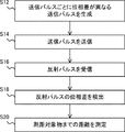
- 3 is a flowchart showing a distance measuring method executed by the distance measuring device according to the first embodiment.
- FIG. 7 is a timing chart showing a relationship between a transmission pulse and a reflection pulse according to a comparative example.
- 7 is a timing chart showing a relationship between a transmission pulse and a reflection pulse according to a comparative example.
- 3 is a timing chart showing a relationship between a transmission pulse and a reflection pulse according to the first exemplary embodiment.
- FIG. 7 is a diagram for explaining the operation of the optical modulator according to the second embodiment.
- FIG. 9 is a diagram illustrating a phase difference table according to the second embodiment.
- FIG. 1 is a diagram showing an outline of a distance measuring device 1 according to an embodiment of the present disclosure.
- FIG. 2 is a diagram showing an outline of a distance measuring method executed by the distance measuring device 1 according to the embodiment of the present disclosure.
- the ranging device 1 includes a generation unit 2 that functions as a generation unit, a transmission unit 4 that functions as a transmission unit, a reception unit 6 that functions as a reception unit, a detection unit 8 that functions as a detection unit, and a distance calculation unit. It has a functioning distance calculation unit 10.
- the generation unit 2 generates a plurality of transmission pulses in which the intensity of the optical signal changes like a pulse. At this time, the generation unit 2 is configured such that the phases of the plurality of regions of the transmission pulse can be different from each other, and the phase difference that is the phase difference in each of the plurality of regions of the transmission pulse depends on the transmission order of the transmission pulses. Generate a plurality of transmit pulses that are configured differently. That is, the generation unit 2 generates a plurality of transmission pulses having different phase differences for each transmission pulse (step S12).
- the transmitter 4 repeatedly transmits the generated transmission pulse (step S14).
- the receiving unit 6 receives the reflection pulse in which the transmission pulse is reflected by the distance measurement target 90 (step S16).
- the detection unit 8 detects the phase difference that is the phase difference in each of the plurality of regions of the received reflected pulse (step S18).
- the distance calculation unit 10 calculates the distance to the target object 90 based on the reception timing of the received reflection pulse and the transmission timing of the transmission pulse corresponding to the phase difference detected from the reflection pulse ( Step S20).
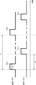
- FIG. 3 is a diagram for explaining the outline of the method of calculating the distance to the distance measurement target 90 using the pulse.
- FIG. 3 shows the operating principle of the ToF method.
- the transmission unit 4 transmits the transmission pulses PlstA and PlstB at the transmission period (pulse period) Tp.
- the pulse width which is the width of each transmission pulse, is Tw.
- the reception unit 6 receives the reflection pulse PlsrA which is the reflected light.
- the transmission pulse PlstB is reflected by the object 90 to be measured
- the reception unit 6 receives the reflection pulse PlsrB which is the reflected light.
- the transmission cycle (pulse cycle) Tp does not have to be constant.
- two transmission pulses PlstA and a transmission pulse PlstB are transmitted at a pulse cycle Tp, and a reflection pulse PlsrA and a reflection pulse PlsrB, which are reflected light of each, are received.
- the time difference Td may be longer than the pulse period Tp.
- the pulse period Tp is short, the time difference Td may be longer than the pulse period Tp. That is, Td>Tp may be satisfied depending on the distance to the distance measurement target 90 or the pulse period.
- the next transmission pulse PlstB is transmitted before the reflection pulse PlsrA is received.
- the distance measuring device 1 according to the present embodiment is configured to generate the transmission pulse such that the phase differences of the plurality of regions of the transmission pulse differ according to the transmission order of the transmission pulse. ..
- the distance measuring apparatus 1 according to the present embodiment generates the transmission pulse Plst1 having the phase difference ⁇ 1 and the transmission pulse Plst2 having the phase difference ⁇ 2.
- the distance measuring apparatus 1 according to the present embodiment is configured to detect the phase difference of the received reflection pulse Plsr1 and associate the transmission pulse Plst1 and the reflection pulse Plsr1 with each other. Therefore, the distance measuring device 1 and the distance measuring method according to the present embodiment can perform the distance measurement properly without depending on the distance to the object to be measured or the transmission cycle of the transmission pulse.
- FIG. 4 is a diagram showing a configuration of the distance measuring device 100 according to the first embodiment.
- the distance measuring apparatus 100 according to the first embodiment includes a phase difference table storage unit 102, a modulation signal generation unit 104, an optical modulator 106, a light source 108, and an optical transmission unit 120 as a transmission system module.
- the phase difference table storage unit 102, the modulation signal generation unit 104, the optical modulator 106, and the light source 108 form a pulse generation unit 110 that generates transmission pulses having different phase differences according to the transmission order.
- the pulse generator 110 corresponds to the generator 2 shown in FIG.
- the optical transmitter 120 corresponds to the transmitter 4 shown in FIG.
- the distance measuring apparatus 100 has a light receiving unit 122, a light source 124, an optical interference system unit 130, a photoelectric conversion unit 132, and an AD converter 134 as a receiving system module.
- the optical receiver 122 corresponds to the receiver 6 shown in FIG.
- the distance measuring apparatus 100 according to the first embodiment includes the phase difference detection unit 152, the reflected pulse identification unit 154, and the distance calculation unit 160.
- the phase difference detection unit 152 corresponds to the detection unit 8 shown in FIG.
- the distance calculation unit 160 corresponds to the distance calculation unit 10 shown in FIG.
- the transmission pulse is divided into two regions, the first half and the second half.
- the phases of the optical signal can be different from each other in the two regions of the first half and the latter half of the transmission pulse.
- the first half phase and the second half phase of the transmission pulse may be different from each other.
- the phase difference which is the difference between these phases, differs depending on the transmission order of the transmission pulses.
- the first half area of the transmission pulse (modulation signal and reflected pulse) may be referred to as area #1
- the second half area may be referred to as area #2.
- “the first half phase and the latter half phase of the transmission pulse may be different from each other” means that the first half phase and the latter half phase may be the same. In this case, the phase difference is 0 degree.
- each of the above-described constituent elements can be realized by some device or a circuit such as an arithmetic circuit.
- the arithmetic circuit is, for example, an FPGA (field-programmable gate array) or the like. This also applies to the other embodiments.
- the phase difference table storage unit 102 stores the phase difference table.
- the phase difference table is a lookup table that associates the transmission order of transmission pulses with the phase difference in the transmission pulses.
- the phase difference table may be associated such that the phase difference in the first transmission pulse is ⁇ 1 and the phase difference in the second transmission pulse is ⁇ 2.
- the phase difference table may associate the order of transmission pulses with the phase in each region, as shown in FIG. 6 described later. As a result, the phase difference table associates the transmission order of the transmission pulses with the phase difference in the transmission pulses.
- the modulation signal generation unit 104 uses the phase difference table stored in the phase difference table storage unit 102 to generate a modulation signal for generating a transmission pulse.
- the modulation signal is an electric signal having a waveform corresponding to the frequency offset f1 and having a phase (phase difference) corresponding to the phase difference table.
- the modulation signal generation unit 104 outputs the generated modulation signal to the optical modulator 106.
- the modulation signal generation unit 104 outputs the measurement start trigger Trgt to the distance calculation unit 160 at the timing when the transmission pulse corresponding to the frequency offset f1 is transmitted.
- the measurement start trigger Trgt indicates the transmission timing of each transmission pulse (Plst1, Plst2, etc.
- the modulation signal generation unit 104 outputs the measurement start trigger Trgt1 to the distance calculation unit 160 at the timing of outputting the modulation signal corresponding to the phase difference ⁇ 1.
- the modulation signal generation unit 104 outputs the measurement start trigger Trgt2 to the distance calculation unit 160 at the timing of outputting the modulation signal corresponding to the phase difference ⁇ 2.
- the modulation signal generation unit 104 outputs the measurement start trigger Trgtn to the distance calculation unit 160 at the timing of outputting the modulation signal corresponding to ⁇ n.
- the light source 108 generates an optical signal having a reference frequency f0 as shown in FIG. 5 described later.
- the optical signal is input to the optical modulator 106.
- the optical modulator 106 uses the modulation signal input from the modulation signal generation unit 104 and the optical signal input from the light source 108 (modulator input signal) to obtain mutually different phase differences ⁇ 1, ⁇ 2,..., ⁇ n. Generate a plurality of transmit pulses having.
- the optical modulator 106 outputs an optical signal including the generated transmission pulse to the optical transmitter 120.
- the optical modulator 106 can be realized by using an I/Q (In Phase/Quadrature Phase) optical modulator in which two Mach-Zehnder modulators are combined.
- the optical modulator 106 modulates an optical signal (modulator input signal) using two modulation signals (I signal and Q signal) whose I/Q signals have different phases by 90 degrees. Thereby, the optical modulator 106 generates a plurality of transmission pulses having different phase differences for each pulse based on the frequency and phase state of the modulation signal.
- FIG. 5 is a diagram for explaining the operation of the optical modulator 106 according to the first embodiment.
- FIG. 6 is a diagram illustrating a phase difference table according to the first embodiment.
- the optical signal input to the optical modulator 106 (modulator input signal) is an optical signal having a constant frequency f0.
- the I signal and the Q signal which are modulation signals, have a pulse-shaped waveform of frequency f1
- the Q signal is a signal whose phase is delayed by 90 degrees with respect to the I signal.
- the amplitude of the modulation signal is 0V except for the pulsed waveform.
- the phase may be different between the region #1 and the region #2 (first half and second half) for each transmission pulse. Then, the phase difference between the phase of the area #1 and the phase of the area #2 is different for each transmission pulse.
- the frequency of light is very high, for example, about 193 THz when the wavelength is 1.55 ⁇ m, and it is difficult to accurately represent it as a wave. Therefore, in FIG.
- the optical signal is schematically represented as a sine wave having a slow cycle. Therefore, in FIG. 5, the waveforms of the modulator input signal, the modulation signal, and the modulator output signal do not always correspond to the frequencies of the respective signals. This also applies to FIG. 11 described later.
- the optical modulator 106 modulates the optical signal according to the pulse-shaped waveform of the modulation signal and outputs the modulated optical signal (modulator output signal).
- This modulator output signal corresponds to the transmitted pulse.
- the modulation signal generation unit 104 generates, as an I signal, a modulation signal in which the phase of the area #1 is 0 degrees and the phase ⁇ 1 of the area #2 is 0 degrees. Generate a modulated signal that is delayed.
- the optical modulator 106 shifts the optical signal of the frequency f0 by f1 and modulates the regions #1 and #2 so that the phases thereof are the same 0 degree. And outputs a pulse of frequency f0+f1.
- the transmission pulse Plst1 is generated.
- the modulated signal generation unit 104 generates, as the I signal, a modulated signal in which the phase of the region #1 is 0 degrees and the phase ⁇ 2 of the region #2 is 90 degrees, and the Q signal is 90 degrees higher than the I signal. Generate a modulated signal that is delayed.
- the optical modulator 106 receives these I and Q signals, it shifts the optical signal of the frequency f0 by f1 so that the phase of the area #1 becomes 0 degrees and the phase of the area #2 becomes 90 degrees. To a pulse of frequency f0+f1.
- the modulation signal generation unit 104 generates, as an I signal, a modulation signal in which the phase of the area #1 is 0 degree and the phase ⁇ 3 of the area #2 is 180 degrees, and the Q signal is 90 degrees higher than the I signal. Generate a modulated signal that is delayed.
- the optical modulator 106 receives the I signal and the Q signal, it shifts the optical signal of the frequency f0 by f1 so that the phase of the area #1 becomes 0 degrees and the phase of the area #2 becomes 180 degrees. To a pulse of frequency f0+f1.
- the transmission pulse indicates a signal whose light intensity changes in a pulse shape. Further, the transmission pulses Plst1, Plst2, Plst3, Plst4 have different phase differences ⁇ 1, ⁇ 2, ⁇ 3, ⁇ 4, respectively.
- the broken line in the modulator output signal indicates the light intensity (envelope).
- the modulation signal generation unit 104 may output the measurement start trigger Trgt1 to the distance calculation unit 160 at the timing of outputting the pulse-shaped modulation signal having the phase difference ⁇ 1.
- the modulation signal generation unit 104 may output the measurement start trigger Trgt2 to the distance calculation unit 160 at the timing of outputting the pulse-shaped modulation signal having the phase difference ⁇ 2.
- the modulation signal generation unit 104 may output the measurement start trigger Trgt3 to the distance calculation unit 160 at the timing of outputting the pulse-shaped modulation signal having the phase difference ⁇ 3.
- the modulation signal generation unit 104 may output the measurement start trigger Trgt4 to the distance calculation unit 160 at the timing of outputting the pulse-shaped waveform modulation signal with the phase difference ⁇ 4.
- the optical transmitter 120 transmits (irradiates) an optical signal including a plurality of transmission pulses (Plst1, Plst2, Plst3, Plst4) to the object 90 for distance measurement.
- the transmitted pulse is reflected by the distance measuring object 90 toward the distance measuring device 100.
- the light receiving unit 122 receives an optical signal including a plurality of reflected pulses reflected by the distance measurement target 90.
- the frequencies of the plurality of reflected pulses received are f0+f1. Note that it is not necessary that a plurality of transmission pulses are applied to the same distance measurement target 90. Therefore, the round-trip flight time of the transmission pulse Plst1 and the round-trip flight time of the transmission pulse Plst2 may be different from each other.
- the plurality of received reflection pulses are formed so that the phase differences of the plurality of regions are different for each reflection pulse. Since the phase noise of the light source 108 on the transmitting side and the light source 124 on the receiving side and the phase noise in the round trip of the optical signal can be superimposed, the phase in each region of the received reflected pulse is in each region of the transmitting pulse. May differ from the phase at.
- phase difference information of the plurality of regions of the reflected pulse is maintained even if the phase noise is superimposed.
- the optical interference system unit 130 detects the frequency offset of the reflected pulse (received light) by using the optical signal of the frequency f0 from the light source 124 as the reference light. Specifically, the optical interference system unit 130 performs heterodyne reception by causing the reference light from the light source 124 and the received light to interfere with each other and detecting the beat frequency. As a result, the frequency of the light source 124 is f0, which is the same as that of the light source 108 on the transmission side, so that the optical interference system unit 130 can detect the frequency offset of the reflected pulse and restore the modulation signal on the transmission side.
- the optical interference system unit 130 may be a mixer using an optical coupler.
- the optical interference system unit 130 outputs the optical signal of the frequency f1 corresponding to the frequency offset to the photoelectric conversion unit 132.
- a light beam obtained by branching the light source 108 on the transmission side may be used instead of the light source 124.
- the photoelectric conversion unit 132 converts an optical signal from the optical interference system unit 130 into an electric signal.
- the photoelectric conversion unit 132 may be, for example, a photoelectric converter using a photo detector or a balanced optical receiver using two photo detectors.
- the AD converter 134 converts the electric signal, which is an analog signal converted by the photoelectric conversion unit 132, into a digital signal.
- the electric signal indicating the frequency f1 converted into a digital signal by the AD converter 134 is output to the phase difference detection unit 152 and the reflected pulse identification unit 154.
- the phase difference detection unit 152 detects the phase difference in the electric signal indicating the frequency f1 corresponding to the reflected pulse. Specifically, the phase difference detection unit 152 calculates the phase for each of the regions corresponding to the regions in the electric pulse indicating the frequency f1 that may have different phases in the transmission pulse. In the first embodiment, since the phase of the transmission pulse may differ between the region #1 (first half) and the region #2 (second half), the phase difference detection unit 152 causes the phase difference detection unit 152 to detect the first half region (region) of the electric signal corresponding to the reflected pulse. The phase is calculated for each of #1) and the latter half area (area #2).
- the phase difference detection unit 152 detects the phase difference ⁇ of the corresponding reflected pulse by calculating the difference between the phase of the area #1 and the phase of the area #2.
- the phase difference detection unit 152 outputs the detected phase difference ⁇ to the reflected pulse identification unit 154.
- the phase difference detection unit 152 can be configured by a phase detector, a phase comparator, or the like, but is not limited to this.
- the reflected pulse identifying unit 154 identifies the transmission pulse Plst corresponding to the phase difference ⁇ detected from the reflected pulse, using the phase difference table stored in the phase difference table storage unit 102. Thereby, the reflected pulse identifying unit 154 associates the reflected pulse Plsr with the transmission pulse Plst. The reflected pulse identifying unit 154 also extracts the reception timing of the reflected pulse having the detected phase difference ⁇ . The reflection pulse specifying unit 154 outputs the measurement stop trigger Trgr corresponding to the specified transmission pulse Plst to the distance calculating unit 160 at the reception timing of the reflection pulse.
- the phase difference detection unit 152 determines that the reflected pulse corresponding to this phase difference ⁇ 1 corresponds to the transmission pulse Plst1. Then, the phase difference detection unit 152 outputs the measurement stop trigger Trgr1 corresponding to the transmission pulse Plst1 to the distance calculation unit 160 at the reception timing of the reflected pulse. Similarly, when the phase difference ⁇ 2 is specified, the phase difference detection unit 152 outputs the measurement stop trigger Trgr2 corresponding to the transmission pulse Plst2 to the distance calculation unit 160 at the reception timing of the reflected pulse.
- the phase difference detection unit 152 outputs the measurement stop trigger Trgr3 corresponding to the transmission pulse Plst3 to the distance calculation unit 160 at the reception timing of the reflected pulse.
- the phase difference detection unit 152 outputs the measurement stop trigger Trgr4 corresponding to the transmission pulse Plst4 to the distance calculation unit 160 at the reception timing of the reflected pulse.
- the distance calculation unit 160 uses Expression 1 from the time difference between the output timing of the measurement start trigger Trgt (first trigger signal) and the output timing of the measurement stop trigger Trgr (second trigger signal) to calculate the distance measurement target object.
- the distance R to 90 is calculated.
- the distance calculation unit 160 calculates the distance R regarding the transmission pulse Plst1 having the phase difference ⁇ 1 from the time difference between the output timing of the measurement start trigger Trgt1 and the output timing of the measurement stop trigger Trgr1.
- the distance calculator 160 calculates the distance R regarding the transmission pulse Plst2 having the phase difference ⁇ 2 from the time difference between the output timing of the measurement start trigger Trgt2 and the output timing of the measurement stop trigger Trgr2.
- the distance calculation unit 160 determines the distance R regarding the transmission pulse having the phase difference ⁇ n from the time difference between the output timing of the measurement start trigger Trgtn and the output timing of the measurement stop trigger Trgrn corresponding to the nth transmission pulse. calculate.
- the phases corresponding to the respective regions of the transmission pulse can be set appropriately so that the phase difference can be detected by the phase difference detection unit 152.
- the phase difference between the regions is preferably as large as possible in consideration of the phase noise of the light source 108 on the transmission side and the light source 124 of the reference light on the reception side and the phase noise superimposed in the round trip process of the transmission pulse.
- the lower limit of the phase difference may be 45 degrees.
- FIG. 7 is a flowchart showing a distance measuring method executed by the distance measuring device 100 according to the first embodiment.
- the pulse generation unit 110 generates transmission pulses having different phase differences ⁇ according to the transmission order (step S102).
- the optical transmission unit 120 transmits (irradiates) the optical signal including the transmission pulse generated in the process of S102 to the distance measurement target 90 (step S104).
- the optical modulator 106 of the pulse generation unit 110 uses the modulation signal generated by the modulation signal generation unit 104 to modulate the optical signal (modulator input signal).
- the optical modulator 106 generates a plurality of transmission pulses having mutually different phase differences.
- this processing means that different phase differences are applied to the respective transmission pulses.
- the measurement start trigger Trgt corresponding to each transmission pulse can be output to the distance calculation unit 160 at the timing of S104.
- the optical receiver 122 receives an optical signal containing a reflected pulse (step S106).
- the optical interference system unit 130 uses the reference light to detect the frequency offset of each reflected pulse (step S108).
- the phase difference detection unit 152 detects the phase difference in the received reflected pulse as described above (step S110).
- the reflected pulse identifying unit 154 identifies the transmission pulse corresponding to the phase difference detected from the reflected pulse, and sets the measurement stop trigger Trgr corresponding to the identified transmission pulse Plst at the reception timing of the reflected pulse.
- Output step S112
- the distance calculation unit 160 calculates the distance R to the distance measurement target 90 using the measurement start trigger Trgt and the measurement stop trigger Trgr (step S114).
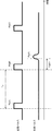
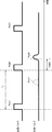
- FIGS. 8 and 9 are timing charts showing the relationship between the transmission pulse and the reflection pulse according to the comparative example.
- the transmission pulses PlstA, PlstB, PlstC are transmitted in the pulse cycle Tp. Further, it is assumed that the transmission pulses PlstA, PlstB, PlstC have the same frequency and phase. Further, in the example shown in FIG. 8, it is assumed that the flight time until the transmission pulse is reflected by the distance measurement target 90 and returns is longer than the pulse period Tp.
- the transmission pulse PlstA is transmitted.
- the reflection pulse PlsrA which is the transmission pulse PlstA reflected by the object 90 to be measured and returned, is received.
- distance measurement may be performed using the time difference Tdiff1' between the transmission timing of the transmission pulse PlstB and the reception timing of the reflection pulse PlsrA. In this way, if distance measurement is performed using the time difference Tdiff1', the distance is erroneously calculated.
- the flight time until the transmission pulse is reflected by the distance measurement target 90 and returns is shorter than the pulse cycle Tp. Furthermore, since the transmission pulse PlstA was not reflected, it is assumed that the reflection pulse PlsrA of the transmission pulse PlstA was not received. It is also assumed that the transmission pulse PlstB is reflected by the object to be measured and the reflection pulse PlsrB is received. In this case, distance measurement is performed using the time difference Tdiff2 between the transmission timing of the transmission pulse PlstB and the reception timing of the reflection pulse PlsrB. Although this distance measuring process is a correct process, it cannot be distinguished from the process shown in FIG.
- the distance measuring apparatus 100 can measure the distance without lengthening the pulse cycle.
- FIG. 10 is a timing chart showing the relationship between the transmission pulse and the reflection pulse according to the first embodiment.
- the transmission pulses Plst1, Plst2, Plst3 are transmitted in the pulse cycle Tp.
- the flight time until the transmission pulse is reflected by the distance measurement target 90 and returns is longer than the pulse period Tp.
- the measurement start trigger Trgt1 is output to the distance calculation unit 160.
- the measurement start trigger Trgt2 is output to the distance calculation unit 160.
- the measurement start trigger Trgt3 is output to the distance calculation unit 160.
- the range finder 100 may also transmit the transmission pulse Plst3 and then transmit the transmission pulse Plst4 having a different phase difference ⁇ 4.
- the distance measuring apparatus 100 may transmit the transmission pulse Plst3 and then transmit the transmission pulse Plst1 again.
- the transmission pulse Plst1 may be transmitted again after it is expected that the round trip flight time of the optical signal has elapsed. This also applies to the other embodiments.
- the reflection pulse Plsr1 is received.
- the frequency offset f1 is detected, the reception timing is extracted, and the measurement stop trigger Trgr1 is output to the distance calculation unit 160.
- the transmitted optical signal is reflected by the object 90 to be measured and is attenuated during the flight of the optical signal.
- the envelope waveform of the reflected pulse Plsr1 becomes dull as compared with the envelope waveform of the transmission pulse Plst1. Therefore, the reflected pulse specifying unit 154 outputs the measurement stop trigger Trgr1 at the timing when the light intensity of the reflected pulse Plsr1 exceeds a predetermined threshold value. This also applies to other reflected pulses Plsr2 and the like.
- the phase of the region #1 of the reflection pulse Plsr1 is ⁇ 0+ ⁇ x1, and the phase of the region #2 is ⁇ 1+ ⁇ x1.
- ⁇ x1 is phase noise superimposed on the reflected pulse Plsr1.
- the reflected pulse specifying unit 154 outputs the measurement stop trigger Trgr1 corresponding to the measurement start trigger Trgt1 to the distance calculation unit 160 at the reception timing of the reflected pulse Plsr1.
- the distance calculation unit 160 calculates the distance to the distance measurement target 90 from the time difference Tdiff1 between the measurement start trigger Trgt1 and the measurement stop trigger Trgr1.
- the reflection pulse Plsr2 is received.
- the frequency offset f1 is detected, the reception timing is extracted, and the measurement stop trigger Trgr2 is output to the distance calculation unit 160.
- the phase of the reflection pulse Plsr2 in the region #1 is ⁇ 0+ ⁇ x2, and the phase of the region #2 is ⁇ 2+ ⁇ x2.
- ⁇ x2 is the phase noise superimposed on the reflected pulse Plsr2.
- the time variation of the phase noise superimposed on the signal is sufficiently long with respect to the pulse width, and the same phase noise ⁇ x2 can be superimposed on the regions #1 and #2.
- the reflection pulse Plsr3 is received after the transmission pulse Plst4 (not shown) is transmitted.
- the frequency offset f1 is detected, the reception timing is extracted, and the measurement stop trigger Trgr3 is output to the distance calculation unit 160.
- the phase of the reflection pulse Plsr3 in the region #1 is ⁇ 0+ ⁇ x3, and the phase of the region #2 is ⁇ 3+ ⁇ x3.
- ⁇ x3 is phase noise superimposed on the reflected pulse Plsr3.
- the distance measuring apparatus 100 associates the measurement start trigger signal related to the transmission pulse having a certain phase difference with the measurement stop trigger signal related to the reflected pulse having this phase difference, and the distance R Is calculated.
- the transmission pulse and the reflection pulse having the phase difference corresponding to each other are associated with each other.
- the distance measuring apparatus 100 according to the first embodiment can appropriately associate the transmission pulse with the reflection pulse that is the reflection light that is reflected by the distance measurement target 90. Therefore, the distance can be appropriately measured without depending on the distance to the object to be measured or the transmission cycle of the transmission pulse.
- the transmission pulse can be distinguished without complicating the structure of the transceiver (transmission system module and reception system module). Further, since the optical signal is transmitted and received by using the optical frequency of only f0+f1, it becomes possible to distinguish the transmission pulse even if the band is narrow.
- the distance measuring apparatus 100 can identify the order of the transmitted pulse of the received reflected pulse by detecting the phase difference in the reflected pulse. As a result, even if the distance to the distance measurement target 90 is long, it is not necessary to lengthen the distance measurement cycle. Further, even if the distance measurement object 90 is continuously irradiated with the transmission pulse at a considerably short cycle, the reflection pulse can be distinguished in the reception system module, so that the distance to the distance measurement object 90 can be calculated appropriately. it can. Furthermore, since it is possible to continuously irradiate the distance measurement target object 90 with the transmission pulse in a considerably short period, it is possible to increase the number of times of distance measurement per unit time.
- the distance measuring apparatus 100 generates the transmission pulse so that the two areas #1 and #2 of the transmission pulse have different phases. Then, the distance measuring apparatus 100 according to the first embodiment determines the transmission pulse corresponding to the reflected pulse by detecting the phase difference between the phase of the area #1 and the phase of the area #2 in the reflected pulse. ing. On the other hand, if each transmission pulse has a single phase and the transmission pulse has a different phase, the transmission pulse is superimposed on the reflection pulse due to the phase noise of the light source 108 and the light source 124. Due to the phase noise, it may not be possible to determine which transmission pulse the phase detected by the reflected pulse corresponds to. Therefore, by thus detecting the "phase difference" of the reflected pulse, the transmission pulse corresponding to the reflected pulse can be reliably determined even when phase noise is superimposed on the reflected pulse. You can
- the phase in each of a plurality of regions of the modulated signal of the frequency offset f1 obtained by offsetting the frequency f0 of the light source from the frequency f0 may be different from each other. Then, the transmission pulse is generated. With this, it is possible to realize that a single transmission pulse has regions having different phases with a simple configuration. In principle, it is also possible to perform phase modulation only on the phase of the light source having the optical frequency f0 without applying the frequency offset f1, and to cause homodyne reception by interfering with the reference light also having the optical frequency f0. However, since the interference components of various lights are down-converted and mixed in the vicinity of the DC component, it becomes difficult to extract only the target distance measurement signal. Therefore, the frequency offset f1 is superimposed and the heterodyne reception is performed. Preferably.
- the distance measuring apparatus 100 uses the phase difference table to generate a plurality of transmission pulses having different phase differences according to the transmission order of the transmission pulses, and uses the phase difference table.
- the reflected pulse and the transmitted pulse are associated with each other. This makes it possible to immediately determine the transmission pulse corresponding to the reflection pulse.
- the second embodiment differs from the first embodiment in that the phases in the three regions of the transmission pulse may be different from each other. Since the constituent elements according to the second embodiment are substantially the same as the constituent elements according to the first embodiment shown in FIG. 4, description thereof will be appropriately omitted.
- the transmission pulse is divided into three areas, front, middle and rear.
- the front area is area #1
- the middle area is area #2
- the rear area is area #3.
- the phase of the optical signal can be different from each other in the three areas of the transmission pulse, area #1, area #2, and area #3.
- the phase difference which is the difference between these phases, differs depending on the transmission order of the transmission pulses. Therefore, the set of the phase difference ⁇ a between the phase of the area #1 and the phase of the area #2 of the transmission pulse and the phase difference ⁇ b between the phase of the area #1 and the phase of the area #3 is the transmission pulse. It depends on the transmission order of.
- the phase difference table stored in the phase difference table storage unit 102 may associate the order of transmission pulses with the phase in each of the three regions, as shown in FIG. 12 described later. Further, in the second embodiment, the phase difference table may associate the transmission order of the transmission pulses with the set of phase differences in the transmission pulses. For example, the phase difference table may associate the pair of phase differences in the first transmission pulse with ( ⁇ a1, ⁇ b1) and the pair of phase differences in the second transmission pulse with ( ⁇ a2, ⁇ b2). Good.
- the modulated signal generation unit 104 uses the phase difference table stored in the phase difference table storage unit 102 to generate the modulated signal for generating the transmission pulse. ..
- the modulation signal generation unit 104 outputs the measurement start trigger Trgt to the distance calculation unit 160 at the timing when the transmission pulse corresponding to the frequency offset f1 is transmitted.
- the light source 108 generates an optical signal having a reference frequency f0 as shown in FIG. 11 described later.
- the optical signal is input to the optical modulator 106.
- the optical modulator 106 uses the modulation signal input from the modulation signal generation unit 104 and the optical signal input from the light source 108 (modulator input signal) to generate a plurality of transmission pulses having different phase difference pairs. To do.
- the optical modulator 106 outputs an optical signal including the generated transmission pulse to the optical transmitter 120.
- FIG. 11 is a diagram for explaining the operation of the optical modulator 106 according to the second embodiment.
- FIG. 12 is a diagram illustrating a phase difference table according to the second embodiment. Similar to FIG. 5, FIG. 11 illustrates three transmission pulses.
- the optical signal input to the optical modulator 106 (modulator input signal) is an optical signal having a constant frequency f0.
- the I signal and the Q signal which are modulation signals, have a pulse-shaped waveform of frequency f1
- the Q signal is a signal whose phase is delayed by 90 degrees with respect to the I signal.
- the amplitude of the modulation signal is 0V except for the pulsed waveform.
- the phase is different in each of the transmission pulses in the area #1, the area #2, and the area #3 (that is, before, during, and after the transmission pulse). obtain. Then, a set ( ⁇ a, ⁇ b) of the phase difference ⁇ a between the phase of the area #1 and the phase of the area #2 and the phase difference ⁇ b between the area #1 and the area #3 is set for each transmission pulse. Different.
- the optical modulator 106 modulates the optical signal according to the pulse-shaped waveform of the modulation signal and outputs the modulated optical signal (modulator output signal).
- This modulator output signal corresponds to the transmitted pulse.
- the set of the phase of the area #2 and the phase of the area #3 of each transmission pulse are different from each other.
- different sets of phase differences are provided for each transmission pulse.
- the phase of region #2 of each transmission pulse is different from each other. Therefore, four types of phases ( ⁇ 1, ⁇ 2, ⁇ 3) are used as the phase of region #2. And ⁇ 4) are required.
- the second embodiment in order to distinguish the four transmission pulses, it is only necessary to use different sets of phase differences. Therefore, there are two types of phases used in the areas #2 and #3 ( ⁇ 1 and ⁇ 2 ) Is good.
- a signal is generated, and a modulated signal delayed by 90 degrees from the I signal is generated as the Q signal.
- the pair ( ⁇ a1, ⁇ b1) with ( ⁇ 1- ⁇ 0) is (0, 0).
- the modulation signal generation unit 104 generates, as the I signal, a modulation signal in which the phase of the area #1 is 0 degrees, the phase of the area #2 is 0 degrees, and the phase of the area #3 is 180 degrees.
- Q signals which are delayed by 90 degrees from the I signals are generated.
- the optical modulator 106 shifts the optical signal of the frequency f0 by f1, and the phase of the area #1 is 0 degrees, the phase of the area #2 is 0 degrees, and the area # It is modulated so that the phase of 3 becomes 180 degrees, and the pulse of frequency f0+f1 is output.
- the transmission pulse Plst2 is generated.
- the modulation signal generation unit 104 generates, as the I signal, a modulation signal in which the phase of the area #1 is 0 degrees, the phase of the area #2 is 180 degrees, and the phase of the area #3 is 0 degrees.
- Q signals which are delayed by 90 degrees from the I signals are generated.
- the modulation signal generation unit 104 outputs the measurement start trigger Trgt1 to the distance calculation unit 160 at the timing of outputting the pulse-shaped modulation signal having the phase difference set of ( ⁇ a1, ⁇ b1). Good.
- the modulation signal generation unit 104 may output the measurement start trigger Trgt2 to the distance calculation unit 160 at the timing of outputting the pulse-shaped waveform modulation signal whose phase difference set is ( ⁇ a2, ⁇ b2). ..
- the modulation signal generation unit 104 may output the measurement start trigger Trgt3 to the distance calculation unit 160 at the timing of outputting the pulse-shaped modulation signal having the phase difference set of ( ⁇ a3, ⁇ b3). ..
- the modulation signal generation unit 104 may output the measurement start trigger Trgt4 to the distance calculation unit 160 at the timing of outputting the pulse-shaped modulation signal having the phase difference set of ( ⁇ a42, ⁇ b4). ..
- the optical transmission unit 120 transmits (irradiates) an optical signal including a plurality of transmission pulses (Plst1, Plst2, Plst3, Plst4) to the distance measurement target 90.
- the transmitted pulse is reflected by the distance measuring object 90 toward the distance measuring device 100.
- the light receiving unit 122 receives an optical signal including a plurality of reflected pulses reflected by the distance measurement target 90.
- the frequencies of the plurality of reflected pulses received are f0+f1.
- each of the plurality of transmission pulses has a different set of phase differences
- the plurality of received reflected pulses are formed so that the set of phase differences of the plurality of regions is different for each reflected pulse.
- the phase noise of the light source 108 on the transmission side and the light source 124 on the reception side and the phase noise in the round trip of the optical signal can be superimposed, the phase in each region of the received reflected pulse corresponds to the transmitted pulse.
- the phase in each region may be different.
- the time variation of these phase noises is sufficiently longer than one pulse width time, the noise superimposed on one pulse is considered to be constant, so the phase difference in a certain reflected pulse is Can be substantially the same.
- the set of phase differences in a given reflected pulse may be substantially the same as the set of phase differences ( ⁇ a, ⁇ b) of the corresponding transmitted pulse.
- the phase difference information of the plurality of regions of the reflected pulse is maintained even if the phase noise is superimposed.
- the operations of the optical interference system unit 130, the photoelectric conversion unit 132, and the AD converter 134 are substantially the same as those in the first embodiment, and thus the description thereof will be omitted.
- the phase difference detection unit 152 detects the phase difference in the electric signal having the frequency f1 and corresponding to the reflected pulse, as in the first embodiment.
- the phase difference detection unit 152 calculates the phase for each of the regions in the electrical signal indicating the frequency f1 that correspond to the regions in which the phase may differ in the transmission pulse.
- the phase of the transmission pulse may be different between region #1 (front) and region #2 (middle) region #3 (rear). Therefore, the phase difference detection unit 152 according to the second embodiment calculates the phase for each of the region #1 (front), the region #2 (middle), and the region #3 (rear) of the electric signal corresponding to the reflected pulse. .. Then, the phase difference detection unit 152 detects one phase difference ⁇ a of the corresponding reflected pulse by calculating the difference between the phase of the area #1 and the phase of the area #2.
- phase difference detection unit 152 detects another phase difference ⁇ b of the corresponding reflected pulse by calculating the difference between the phase of the area #1 and the phase of the area #3.
- the phase difference detection unit 152 outputs a set ( ⁇ a, ⁇ b) of the detected phase difference ⁇ a and phase difference ⁇ b to the reflected pulse identification unit 154.
- the reflected pulse identifying unit 154 identifies the transmission pulse Plst corresponding to the pair of phase differences ( ⁇ a, ⁇ b) detected from the reflected pulse using the phase difference table stored in the phase difference table storage unit 102. Thereby, the reflected pulse identifying unit 154 associates the reflected pulse Plsr with the transmission pulse Plst. Further, the reflected pulse identifying unit 154 extracts the reception timing of the reflected pulse having the detected pair of phase differences ( ⁇ a, ⁇ b). The reflection pulse specifying unit 154 outputs the measurement stop trigger Trgr corresponding to the specified transmission pulse Plst to the distance calculating unit 160 at the reception timing of the reflection pulse.
- the phase difference detection unit 152 determines that the reflection pulse corresponding to this pair of phase differences ( ⁇ a1, ⁇ b1) corresponds to the transmission pulse Plst1. Then, the phase difference detection unit 152 outputs the measurement stop trigger Trgr1 corresponding to the transmission pulse Plst1 to the distance calculation unit 160 at the reception timing of the reflected pulse. Similarly, when the pair of phase differences ( ⁇ a2, ⁇ b2) is specified, the phase difference detection unit 152 sets the measurement stop trigger Trgr2 corresponding to the transmission pulse Plst2 at the reception timing of the reflection pulse and the distance calculation unit 160. Output to.
- the phase difference detection unit 152 when the set of phase differences ( ⁇ a3, ⁇ b3) is specified, the phase difference detection unit 152 also sets the measurement stop trigger Trgr3 corresponding to the transmission pulse Plst3 to the distance calculation unit 160 at the reception timing of the reflected pulse. Output to. Similarly, when the set of phase differences ( ⁇ a4, ⁇ b4) is specified, the phase difference detection unit 152 sets the measurement stop trigger Trgr4 corresponding to the transmission pulse Plst4 at the reception timing of the reflected pulse and the distance calculation unit 160. Output to.
- the distance calculation unit 160 uses Expression 1 from the time difference between the output timing of the measurement start trigger Trgt (first trigger signal) and the output timing of the measurement stop trigger Trgr (second trigger signal) to calculate the distance measurement target object.
- the distance R to 90 is calculated.
- the distance calculation unit 160 calculates the distance R regarding the transmission pulse Plst1 having the set of phase differences ( ⁇ a1, ⁇ b1) from the time difference between the output timing of the measurement start trigger Trgt1 and the output timing of the measurement stop trigger Trgr1.
- the distance calculation unit 160 calculates the distance R regarding the transmission pulse Plst2 having the phase difference set ( ⁇ a2, ⁇ b2) from the time difference between the output timing of the measurement start trigger Trgt2 and the output timing of the measurement stop trigger Trgr2.
- the distance calculation unit 160 relates to the transmission pulse having the pair of phase differences ( ⁇ an, ⁇ bn) from the time difference between the output timing of the measurement start trigger Trgtn and the output timing of the measurement stop trigger Trgrn corresponding to the nth transmission pulse.
- the distance R is calculated.
- the distance measuring apparatus 100 associates the measurement start trigger signal regarding the transmission pulse having a certain phase difference pair with the measurement stop trigger signal regarding the reflected pulse having this phase difference pair. Then, the distance R is calculated.
- the transmission pulse and the reflection pulse having the pair of phase differences corresponding to each other are associated with each other.
- the distance measuring apparatus 100 according to the second embodiment appropriately sets the transmission pulse and the reflection pulse that is the reflected light reflected by the distance measurement target 90 by the transmission pulse. Can be associated. Therefore, also in the second embodiment, it is possible to perform the distance measurement properly without depending on the distance to the object to be measured or the transmission cycle of the transmission pulse.
- the distance measuring apparatus 100 according to the second embodiment generates the transmission pulse so that the three regions of one transmission pulse have mutually different phases. Then, the distance measuring apparatus 100 according to the second embodiment provides the phase difference between the phase of the region #1 and the phase of the region #2 in the reflected pulse, the phase difference of the region #1 and the phase of the region #3. The transmission pulse corresponding to the reflected pulse is determined by detecting the pair with the phase difference.
- four transmission pulses (reflection pulses) can be specified only by using two phases (0 degrees and 180 degrees).
- the minimum value (excluding 0 degrees) of the phase difference between regions in one transmission pulse is 90 degrees.
- the minimum value (excluding 0 degrees) of the phase difference between regions in one transmission pulse is 180 degrees.
- the minimum value of the phase difference between the regions in one transmission pulse can be increased as compared with the case of the first embodiment.
- the accuracy of the phase detection of the distance measuring device 100 phase difference detection unit 152
- the method of the first embodiment may not be able to properly detect the phase difference between the regions in one reflected pulse, and thus may not be able to perform distance measurement properly.
- the distance measuring apparatus 100 can correlate the reflected pulse and the transmitted pulse even when the phase detection accuracy is low, so that the distance can be appropriately measured. Become.
- the distance measuring apparatus 100 when the phase difference of 90 degrees can be detected, if the phase is set to one of 0 degrees, 90 degrees, 180 degrees, and 270 degrees in the three regions, 16 phase differences are obtained.
- the transmission pulse of can be realized. Therefore, the distance measuring apparatus 100 according to the second embodiment can generate many different transmission pulses as compared with the first embodiment.
- the distance measuring apparatus 100 according to the first embodiment since there are only two regions in one transmission pulse, the pulse waveform is not complicated as compared with the waveform in the second embodiment. Therefore, the distance measuring apparatus 100 according to the first embodiment can easily generate the transmission pulse as compared with the second embodiment. Further, while the phase difference detection unit 152 according to the second embodiment needs to detect two phase differences for one reflected pulse, the phase difference detection unit 152 according to the first embodiment has one reflection. It suffices to detect one phase difference for the pulse. Therefore, the distance measuring apparatus 100 according to the first embodiment can detect the phase difference with a simple process as compared with the second embodiment.
- the present invention is not limited to the above-mentioned embodiments, but can be modified as appropriate without departing from the spirit of the present invention.
- the phase of the first region (region #1) of the transmission pulse is 0 degree, but the phase is not limited to this.
- the phase of the area #1 may be an arbitrary phase.
- the phase of region #1 does not have to be the same.
- the phase of the area #1 of the transmission pulse Plst1 may be 0 degrees
- the phase of the area #1 of the transmission pulse Plst2 may be 180 degrees. That is, if the phase difference is made different for each transmission pulse, it is arbitrary which region the phase is used as a reference and which reference phase is set. This also applies to the second embodiment.
- phase difference ⁇ a between the phase of the region #1 and the phase of the region #2 of the transmission pulse and the phase difference ⁇ b between the phase of the region #1 and the phase of the region #3 is assumed to be different for each transmission pulse.
- the phase difference here does not have to be the difference between the phase of the area #1 and the phase of the other areas.
- the set of the phase difference ⁇ a between the phase of the transmission pulse and the phase of the region #1 and the phase difference ⁇ b between the phase of the region #2 and the phase of the region #3 is different for each transmission pulse. Good.
- the phases of the three regions of the transmission pulse may be different, but the configuration is not limited to such a configuration.
- the number of regions in one transmission pulse may be four or more. That is, the transmission pulse is configured such that the phases in each of the N areas (N is an integer of 3 or more) can be different from each other, and the phase difference, which is the phase difference in each of the N areas, depends on the transmission order of the transmission pulses. May be configured differently. By increasing the number of areas of the transmission pulse, the reflection pulse and the transmission pulse can be associated with each other without increasing the types of phases used.
- the distance calculation unit 160 may consider the processing time in the optical modulator 106 or the like in the output timing of the measurement start trigger. In other words, the distance calculation unit 160 may consider the processing time from the acceptance of the measurement start trigger to the actual transmission of the transmission pulse corresponding to the measurement start trigger. In this case, the distance calculation unit 160 may use the timing obtained by adding the processing time in the optical modulator 106 and the like to the output timing of the measurement start trigger as the distance measurement start timing.
- the processing time in the optical modulator 106 and the like is assumed to be substantially constant.
- the distance calculation unit 160 may consider, for the measurement stop trigger, the processing time of the optical interference system unit 130 and the like before the measurement stop trigger is output. In other words, the distance calculation unit 160 may consider the processing time from the reception of the reflected pulse by the optical receiver 122 to the output of the measurement stop trigger by the reflected pulse identifying unit 154. In this case, the distance calculation unit 160 may set the timing obtained by subtracting the processing time of the optical interference system unit 130 from the output timing of the measurement stop trigger as the end timing of the distance measurement. The processing time in the optical interference system unit 130 and the like is assumed to be substantially constant.
- the modulated signal generation unit 104 may output a measurement start trigger indicating the time when the transmission pulse is transmitted, in consideration of the processing time until the transmission pulse is transmitted by the optical transmission unit 120 in the subsequent stage. Good. That is, assuming that the time when the modulated signal is generated is t1 and the processing time in the optical modulator 106 and the like is ⁇ t1, the modulated signal generation unit 104 may output the measurement start trigger indicating the time (t1+ ⁇ t1). Similarly, the reflected pulse identifying unit 154 may output a measurement stop trigger indicating the time when the reflected pulse is received, in consideration of the processing time in the optical interference system unit 130 or the like in the preceding stage.
- a highly accurate distance R may be calculated in consideration of the total processing time of each processing unit by performing calibration based on a time difference when a known distance is measured in advance.
- the present embodiment has been described as a hardware configuration, but the present embodiment is not limited to this.
- the present embodiment can also be realized by causing a CPU (Central Processing Unit) to execute a computer program for at least one process of each circuit in the distance measuring device.
- a CPU Central Processing Unit
- Non-transitory computer-readable media include various types of tangible storage media.
- Examples of non-transitory computer-readable media are magnetic recording media (eg flexible disks, magnetic tapes, hard disk drives), magneto-optical recording media (eg magneto-optical disks), CD-ROMs (Read Only Memory), CD-Rs, It includes a CD-R/W and a semiconductor memory (for example, mask ROM, PROM (Programmable ROM), EPROM (Erasable PROM), flash ROM, RAM (Random Access Memory)).
- the program may be supplied to the computer by various types of transitory computer readable media. Examples of transitory computer-readable media include electrical signals, optical signals, and electromagnetic waves.
- the transitory computer-readable medium can supply the program to the computer via a wired communication path such as an electric wire and an optical fiber, or a wireless communication path.
- the generation means is configured such that the phases of the two regions of the transmission pulse can be different from each other, and the phase difference, which is the phase difference between the two regions of the transmission pulse, depends on the transmission order of the transmission pulses.
- the distance measuring device according to appendix 1 which generates a plurality of transmission pulses that are configured differently.
- the generation means is configured such that the phases of the N or more regions of the transmission pulse can be different from each other, and the phase difference, which is the phase difference in each of the N regions of the transmission pulse, of the transmission pulse is The distance measuring apparatus according to appendix 1, which generates a plurality of transmission pulses that are configured to be different according to a transmission order.
- the generating unit generates the transmission pulse by modulating an optical signal of a reference frequency so that phases of a plurality of regions of a modulation signal of a frequency offset with respect to the reference frequency can be different from each other.
- the distance measuring device according to any one of 1 to 3.
- the generation means generates the plurality of transmission pulses by using a phase difference table that associates the transmission order and the phase difference of the transmission pulses,
- the distance calculation means calculates the distance to the object to be measured based on the reception timing of the reflection pulse and the transmission timing of the transmission pulse associated with the reflection pulse using the phase difference table.
- the distance measuring device according to any one of appendices 1 to 4.
- the transmission pulse is generated by modulating an optical signal of a reference frequency so that phases of a plurality of regions of a modulation signal of a frequency offset with respect to the reference frequency may be different from each other.
- the distance measuring method according to item 1. (Appendix 10) Generating the plurality of transmission pulses using a phase difference table that associates the transmission order and phase difference of the transmission pulses, The distance to the object to be measured is calculated based on the reception timing of the reflection pulse and the transmission timing of the transmission pulse associated with the reflection pulse using the phase difference table.
- the distance measuring method according to any one of items.
- distance measuring device 2 generating unit 4 transmitting unit 6 receiving unit 8 detecting unit 10 distance calculating unit 100 distance measuring device 102 phase difference table storing unit 104 modulation signal generating unit 106 optical modulator 108 light source 110 pulse generating unit 120 optical transmitting unit 122 Light receiving unit 124 Light source 130 Optical interference system unit 132 Photoelectric converting unit 134 AD converter 152 Phase difference detecting unit 154 Reflection pulse specifying unit 160 Distance calculating unit
Landscapes
- Physics & Mathematics (AREA)
- Engineering & Computer Science (AREA)
- Electromagnetism (AREA)
- Computer Networks & Wireless Communication (AREA)
- General Physics & Mathematics (AREA)
- Radar, Positioning & Navigation (AREA)
- Remote Sensing (AREA)
- Optical Radar Systems And Details Thereof (AREA)
- Measurement Of Optical Distance (AREA)
Abstract
Description
本開示の実施形態の説明に先立って、本開示にかかる実施の形態の概要について説明する。図1は、本開示の実施の形態にかかる測距装置1の概要を示す図である。また、図2は、本開示の実施の形態にかかる測距装置1によって実行される測距方法の概要を示す図である。
(式1)R=c×Td/2
これにより、距離算出部10によって、距離Rが算出される。
次に、実施の形態1について説明する。
図4は、実施の形態1にかかる測距装置100の構成を示す図である。実施の形態1にかかる測距装置100は、送信系モジュールとして、位相差テーブル格納部102と、変調信号生成部104と、光変調器106と、光源108と、光送信部120とを有する。位相差テーブル格納部102、変調信号生成部104、光変調器106及び光源108によって、送信順序に応じて異なる位相差を有する送信パルスを生成するパルス生成部110が構成される。このパルス生成部110は、図1に示した生成部2に対応する。また、光送信部120は、図1に示した送信部4に対応する。
次に、実施の形態1と比較例とを、タイミングチャートを用いて説明する。
図8及び図9は、比較例にかかる送信パルスと反射パルスとの関係を示すタイミングチャートである。図8及び図9に示す例では、送信パルスPlstA,PlstB,PlstCが、パルス周期Tpで送信されるとする。また、送信パルスPlstA,PlstB,PlstCの周波数及び位相は同じであるとする。さらに、図8に示す例では、送信パルスが測距対象物90に反射して戻ってくるまでの飛行時間が、パルス周期Tpよりも長いとする。
次に、実施の形態2について説明する。実施の形態2においては、送信パルスの3つの領域それぞれにおける位相が互いに異なり得る点で、実施の形態1と異なる。なお、実施の形態2にかかる構成要素は、図4に示した実施の形態1における構成要素と実質的に同じであるので、適宜、説明を省略する。
なお、本発明は上記実施の形態に限られたものではなく、趣旨を逸脱しない範囲で適宜変更することが可能である。例えば、上述した実施の形態では、送信パルスの最初の領域(領域#1)の位相が0度であるとしたが、これに限られない。領域#1の位相は、任意の位相であってもよい。さらに、各送信パルスで、領域#1の位相は同じである必要はない。例えば、送信パルスPlst1の領域#1の位相を0度とし、送信パルスPlst2の領域#1の位相を180度としてもよい。つまり、各送信パルスで位相差が異なるようにすれば、どの領域の位相を基準とするか、及び基準とする位相を何度にするかは、任意である。このことは、実施の形態2においても同様である。
(付記1)
光信号の強度がパルス状に変化した複数の送信パルスであって、前記送信パルスの複数の領域それぞれにおける位相が互いに異なり得るように構成され、前記送信パルスの複数の領域それぞれにおける位相の差である位相差が前記送信パルスの送信順序に応じて異なるように構成された、複数の送信パルスを生成する生成手段と、
生成された前記送信パルスを繰り返し送信する送信手段と、
前記送信パルスが測距対象物で反射した反射パルスを受信する受信手段と、
受信された前記反射パルスの複数の領域それぞれにおける位相の差である位相差を検出する検出手段と、
受信された前記反射パルスの受信タイミングと、当該反射パルスから検出された前記位相差に対応する前記送信パルスの送信タイミングとに基づいて、前記測距対象物までの距離を算出する距離算出手段と
を有する測距装置。
(付記2)
前記生成手段は、前記送信パルスの2つの領域それぞれにおける位相が互いに異なり得るように構成され、前記送信パルスの2つの領域それぞれにおける位相の差である位相差が前記送信パルスの送信順序に応じて異なるように構成された、複数の送信パルスを生成する
付記1に記載の測距装置。
(付記3)
前記生成手段は、前記送信パルスの3以上のN個の領域それぞれにおける位相が互いに異なり得るように構成され、前記送信パルスのN個の領域それぞれにおける位相の差である位相差が前記送信パルスの送信順序に応じて異なるように構成された、複数の送信パルスを生成する
付記1に記載の測距装置。
(付記4)
前記生成手段は、基準周波数の光信号を、前記基準周波数に対してオフセットした周波数の変調信号の複数の領域それぞれにおける位相が互いに異なり得るようにして変調することで、前記送信パルスを生成する
付記1~3のいずれか1項に記載の測距装置。
(付記5)
前記生成手段は、前記送信パルスの送信順序と位相差とを対応付ける位相差テーブルを用いて前記複数の送信パルスを生成し、
前記距離算出手段は、前記反射パルスの受信タイミングと、前記位相差テーブルを用いて前記反射パルスと対応付けられた前記送信パルスの送信タイミングとに基づいて、前記測距対象物までの距離を算出する
付記1~4のいずれか1項に記載の測距装置。
(付記6)
光信号の強度がパルス状に変化した複数の送信パルスであって、前記送信パルスの複数の領域それぞれにおける位相が互いに異なり得るように構成され、前記送信パルスの複数の領域それぞれにおける位相の差である位相差が前記送信パルスの送信順序に応じて異なるように構成された、複数の送信パルスを生成し、
生成された前記送信パルスを繰り返し送信し、
前記送信パルスが測距対象物で反射した反射パルスを受信し、
受信された前記反射パルスの複数の領域それぞれにおける位相の差である位相差を検出し、
受信された前記反射パルスの受信タイミングと、当該反射パルスから検出された前記位相差に対応する前記送信パルスの送信タイミングとに基づいて、前記測距対象物までの距離を算出する
測距方法。
(付記7)
前記送信パルスの2つの領域それぞれにおける位相が互いに異なり得るように構成され、前記送信パルスの2つの領域それぞれにおける位相の差である位相差が前記送信パルスの送信順序に応じて異なるように構成された、複数の送信パルスを生成する
付記6に記載の測距方法。
(付記8)
前記送信パルスの3以上のN個の領域それぞれにおける位相が互いに異なり得るように構成され、前記送信パルスのN個の領域それぞれにおける位相の差である位相差が前記送信パルスの送信順序に応じて異なるように構成された、複数の送信パルスを生成する
付記6に記載の測距方法。
(付記9)
基準周波数の光信号を、前記基準周波数に対してオフセットした周波数の変調信号の複数の領域それぞれにおける位相が互いに異なり得るようにして変調することで、前記送信パルスを生成する
付記6~8のいずれか1項に記載の測距方法。
(付記10)
前記送信パルスの送信順序と位相差とを対応付ける位相差テーブルを用いて前記複数の送信パルスを生成し、
前記反射パルスの受信タイミングと、前記位相差テーブルを用いて前記反射パルスと対応付けられた前記送信パルスの送信タイミングとに基づいて、前記測距対象物までの距離を算出する
付記6~9のいずれか1項に記載の測距方法。
2 生成部
4 送信部
6 受信部
8 検出部
10 距離算出部
100 測距装置
102 位相差テーブル格納部
104 変調信号生成部
106 光変調器
108 光源
110 パルス生成部
120 光送信部
122 光受信部
124 光源
130 光干渉系ユニット
132 光電変換部
134 ADコンバータ
152 位相差検出部
154 反射パルス特定部
160 距離算出部
Claims (10)
- 光信号の強度がパルス状に変化した複数の送信パルスであって、前記送信パルスの複数の領域それぞれにおける位相が互いに異なり得るように構成され、前記送信パルスの複数の領域それぞれにおける位相の差である位相差が前記送信パルスの送信順序に応じて異なるように構成された、複数の送信パルスを生成する生成手段と、
生成された前記送信パルスを繰り返し送信する送信手段と、
前記送信パルスが測距対象物で反射した反射パルスを受信する受信手段と、
受信された前記反射パルスの複数の領域それぞれにおける位相の差である位相差を検出する検出手段と、
受信された前記反射パルスの受信タイミングと、当該反射パルスから検出された前記位相差に対応する前記送信パルスの送信タイミングとに基づいて、前記測距対象物までの距離を算出する距離算出手段と
を有する測距装置。 - 前記生成手段は、前記送信パルスの2つの領域それぞれにおける位相が互いに異なり得るように構成され、前記送信パルスの2つの領域それぞれにおける位相の差である位相差が前記送信パルスの送信順序に応じて異なるように構成された、複数の送信パルスを生成する
請求項1に記載の測距装置。 - 前記生成手段は、前記送信パルスの3以上のN個の領域それぞれにおける位相が互いに異なり得るように構成され、前記送信パルスのN個の領域それぞれにおける位相の差である位相差が前記送信パルスの送信順序に応じて異なるように構成された、複数の送信パルスを生成する
請求項1に記載の測距装置。 - 前記生成手段は、基準周波数の光信号を、前記基準周波数に対してオフセットした周波数の変調信号の複数の領域それぞれにおける位相が互いに異なり得るようにして変調することで、前記送信パルスを生成する
請求項1~3のいずれか1項に記載の測距装置。 - 前記生成手段は、前記送信パルスの送信順序と位相差とを対応付ける位相差テーブルを用いて前記複数の送信パルスを生成し、
前記距離算出手段は、前記反射パルスの受信タイミングと、前記位相差テーブルを用いて前記反射パルスと対応付けられた前記送信パルスの送信タイミングとに基づいて、前記測距対象物までの距離を算出する
請求項1~4のいずれか1項に記載の測距装置。 - 光信号の強度がパルス状に変化した複数の送信パルスであって、前記送信パルスの複数の領域それぞれにおける位相が互いに異なり得るように構成され、前記送信パルスの複数の領域それぞれにおける位相の差である位相差が前記送信パルスの送信順序に応じて異なるように構成された、複数の送信パルスを生成し、
生成された前記送信パルスを繰り返し送信し、
前記送信パルスが測距対象物で反射した反射パルスを受信し、
受信された前記反射パルスの複数の領域それぞれにおける位相の差である位相差を検出し、
受信された前記反射パルスの受信タイミングと、当該反射パルスから検出された前記位相差に対応する前記送信パルスの送信タイミングとに基づいて、前記測距対象物までの距離を算出する
測距方法。 - 前記送信パルスの2つの領域それぞれにおける位相が互いに異なり得るように構成され、前記送信パルスの2つの領域それぞれにおける位相の差である位相差が前記送信パルスの送信順序に応じて異なるように構成された、複数の送信パルスを生成する
請求項6に記載の測距方法。 - 前記送信パルスの3以上のN個の領域それぞれにおける位相が互いに異なり得るように構成され、前記送信パルスのN個の領域それぞれにおける位相の差である位相差が前記送信パルスの送信順序に応じて異なるように構成された、複数の送信パルスを生成する
請求項6に記載の測距方法。 - 基準周波数の光信号を、前記基準周波数に対してオフセットした周波数の変調信号の複数の領域それぞれにおける位相が互いに異なり得るようにして変調することで、前記送信パルスを生成する
請求項6~8のいずれか1項に記載の測距方法。 - 前記送信パルスの送信順序と位相差とを対応付ける位相差テーブルを用いて前記複数の送信パルスを生成し、
前記反射パルスの受信タイミングと、前記位相差テーブルを用いて前記反射パルスと対応付けられた前記送信パルスの送信タイミングとに基づいて、前記測距対象物までの距離を算出する
請求項6~9のいずれか1項に記載の測距方法。
Priority Applications (4)
| Application Number | Priority Date | Filing Date | Title |
|---|---|---|---|
| JP2021501420A JP7192959B2 (ja) | 2019-02-26 | 2019-02-26 | 測距装置及び測距方法 |
| PCT/JP2019/007235 WO2020174567A1 (ja) | 2019-02-26 | 2019-02-26 | 測距装置及び測距方法 |
| EP19916904.6A EP3933440B1 (en) | 2019-02-26 | 2019-02-26 | Distance measurement device and distance measurement method |
| US17/432,561 US20220146674A1 (en) | 2019-02-26 | 2019-02-26 | Distance-measurement apparatus and distance-measurement method |
Applications Claiming Priority (1)
| Application Number | Priority Date | Filing Date | Title |
|---|---|---|---|
| PCT/JP2019/007235 WO2020174567A1 (ja) | 2019-02-26 | 2019-02-26 | 測距装置及び測距方法 |
Publications (1)
| Publication Number | Publication Date |
|---|---|
| WO2020174567A1 true WO2020174567A1 (ja) | 2020-09-03 |
Family
ID=72239159
Family Applications (1)
| Application Number | Title | Priority Date | Filing Date |
|---|---|---|---|
| PCT/JP2019/007235 Ceased WO2020174567A1 (ja) | 2019-02-26 | 2019-02-26 | 測距装置及び測距方法 |
Country Status (4)
| Country | Link |
|---|---|
| US (1) | US20220146674A1 (ja) |
| EP (1) | EP3933440B1 (ja) |
| JP (1) | JP7192959B2 (ja) |
| WO (1) | WO2020174567A1 (ja) |
Families Citing this family (1)
| Publication number | Priority date | Publication date | Assignee | Title |
|---|---|---|---|---|
| JP2021028583A (ja) * | 2019-08-09 | 2021-02-25 | 株式会社東海理化電機製作所 | 制御装置およびプログラム |
Citations (6)
| Publication number | Priority date | Publication date | Assignee | Title |
|---|---|---|---|---|
| JP2002139565A (ja) * | 2000-11-02 | 2002-05-17 | Toshiba Corp | レーダ装置 |
| JP2008249541A (ja) * | 2007-03-30 | 2008-10-16 | Mitsubishi Electric Corp | パルス信号検出装置 |
| JP2010145346A (ja) * | 2008-12-22 | 2010-07-01 | Mitsubishi Electric Corp | パルス圧縮レーダ装置 |
| JP2012052920A (ja) * | 2010-09-01 | 2012-03-15 | Panasonic Corp | レーダ装置 |
| JP2013088313A (ja) * | 2011-10-19 | 2013-05-13 | Japan Radio Co Ltd | レーダ装置 |
| JP2016148634A (ja) * | 2015-02-13 | 2016-08-18 | 三菱電機株式会社 | 目標検出装置 |
Family Cites Families (5)
| Publication number | Priority date | Publication date | Assignee | Title |
|---|---|---|---|---|
| EP3374788B1 (en) * | 2015-11-13 | 2022-06-01 | Teledyne Flir, LLC | Detection and ranging system and method |
| US10690756B2 (en) * | 2016-05-10 | 2020-06-23 | Texas Instruments Incorporated | Methods and apparatus for LIDAR operation with pulse position modulation |
| US20170372602A1 (en) * | 2016-06-24 | 2017-12-28 | Continental Advanced Lidar Solutions Us, Llc | Ladar enabled traffic control |
| US10422880B2 (en) * | 2017-02-03 | 2019-09-24 | Blackmore Sensors and Analytics Inc. | Method and system for doppler detection and doppler correction of optical phase-encoded range detection |
| US10754011B2 (en) * | 2018-06-29 | 2020-08-25 | Perceptive Inc. | Perception systems for use in autonomously controlling systems |
-
2019
- 2019-02-26 US US17/432,561 patent/US20220146674A1/en active Pending
- 2019-02-26 JP JP2021501420A patent/JP7192959B2/ja active Active
- 2019-02-26 EP EP19916904.6A patent/EP3933440B1/en active Active
- 2019-02-26 WO PCT/JP2019/007235 patent/WO2020174567A1/ja not_active Ceased
Patent Citations (6)
| Publication number | Priority date | Publication date | Assignee | Title |
|---|---|---|---|---|
| JP2002139565A (ja) * | 2000-11-02 | 2002-05-17 | Toshiba Corp | レーダ装置 |
| JP2008249541A (ja) * | 2007-03-30 | 2008-10-16 | Mitsubishi Electric Corp | パルス信号検出装置 |
| JP2010145346A (ja) * | 2008-12-22 | 2010-07-01 | Mitsubishi Electric Corp | パルス圧縮レーダ装置 |
| JP2012052920A (ja) * | 2010-09-01 | 2012-03-15 | Panasonic Corp | レーダ装置 |
| JP2013088313A (ja) * | 2011-10-19 | 2013-05-13 | Japan Radio Co Ltd | レーダ装置 |
| JP2016148634A (ja) * | 2015-02-13 | 2016-08-18 | 三菱電機株式会社 | 目標検出装置 |
Also Published As
| Publication number | Publication date |
|---|---|
| JPWO2020174567A1 (ja) | 2021-09-30 |
| EP3933440A4 (en) | 2022-02-16 |
| EP3933440B1 (en) | 2026-04-08 |
| EP3933440A1 (en) | 2022-01-05 |
| US20220146674A1 (en) | 2022-05-12 |
| JP7192959B2 (ja) | 2022-12-20 |
Similar Documents
| Publication | Publication Date | Title |
|---|---|---|
| JP5590884B2 (ja) | 光学距離測定方法及びそれを用いた光学距離測定装置 | |
| JP6410258B2 (ja) | 光波距離計 | |
| JP6653695B2 (ja) | レーザー位相推定及び補正 | |
| US9025141B1 (en) | Position determination using synthetic wave laser ranging | |
| JP6274368B1 (ja) | レーザレーダ装置 | |
| US9599714B2 (en) | Wind measurement coherent lidar | |
| US20100153062A1 (en) | System and method for laser range-finding | |
| JP6792933B2 (ja) | 合成波レーザー測距センサ及び方法 | |
| US12372618B2 (en) | Distance measuring device and measuring method by using visible laser and near-infrared pulse laser | |
| JP2015094760A5 (ja) | ||
| US10408925B1 (en) | Low probability of intercept laser range finder | |
| US9798004B2 (en) | Laser ranging sensors and methods that use a ladder of synthetic waves having increasing wavelengths to calculate a distance measurement | |
| JP2018059789A (ja) | 距離測定装置及び距離測定方法 | |
| JP7192959B2 (ja) | 測距装置及び測距方法 | |
| JPWO2020079775A1 (ja) | 測距装置及び測距方法 | |
| JP7111170B2 (ja) | 測距装置及び測距方法 | |
| WO2008023726A1 (fr) | Appareil de radar et procédé de mesure de la distance | |
| JP2019078531A (ja) | 光波距離計及びフィードバック信号の変調周波数決定方法 | |
| JP6653052B2 (ja) | レーザー測距装置およびレーザー測距方法 | |
| Manzur | Low Probability of Intercept Laser Range Finder | |
| JP2006292461A (ja) | 距離計 |
Legal Events
| Date | Code | Title | Description |
|---|---|---|---|
| 121 | Ep: the epo has been informed by wipo that ep was designated in this application |
Ref document number: 19916904 Country of ref document: EP Kind code of ref document: A1 |
|
| ENP | Entry into the national phase |
Ref document number: 2021501420 Country of ref document: JP Kind code of ref document: A |
|
| NENP | Non-entry into the national phase |
Ref country code: DE |
|
| ENP | Entry into the national phase |
Ref document number: 2019916904 Country of ref document: EP Effective date: 20210927 |
|
| WWG | Wipo information: grant in national office |
Ref document number: 2019916904 Country of ref document: EP |