WO2020174623A1 - Dispositif de traitement d'informations, corps mobile et dispositif d'apprentissage - Google Patents
Dispositif de traitement d'informations, corps mobile et dispositif d'apprentissage Download PDFInfo
- Publication number
- WO2020174623A1 WO2020174623A1 PCT/JP2019/007653 JP2019007653W WO2020174623A1 WO 2020174623 A1 WO2020174623 A1 WO 2020174623A1 JP 2019007653 W JP2019007653 W JP 2019007653W WO 2020174623 A1 WO2020174623 A1 WO 2020174623A1
- Authority
- WO
- WIPO (PCT)
- Prior art keywords
- image
- detection image
- feature amount
- visible light
- learning
- Prior art date
- Legal status (The legal status is an assumption and is not a legal conclusion. Google has not performed a legal analysis and makes no representation as to the accuracy of the status listed.)
- Ceased
Links
Images







Classifications
-
- G—PHYSICS
- G06—COMPUTING OR CALCULATING; COUNTING
- G06T—IMAGE DATA PROCESSING OR GENERATION, IN GENERAL
- G06T7/00—Image analysis
- G06T7/70—Determining position or orientation of objects or cameras
- G06T7/73—Determining position or orientation of objects or cameras using feature-based methods
- G06T7/74—Determining position or orientation of objects or cameras using feature-based methods involving reference images or patches
-
- G—PHYSICS
- G06—COMPUTING OR CALCULATING; COUNTING
- G06T—IMAGE DATA PROCESSING OR GENERATION, IN GENERAL
- G06T7/00—Image analysis
- G06T7/70—Determining position or orientation of objects or cameras
- G06T7/73—Determining position or orientation of objects or cameras using feature-based methods
-
- H—ELECTRICITY
- H04—ELECTRIC COMMUNICATION TECHNIQUE
- H04N—PICTORIAL COMMUNICATION, e.g. TELEVISION
- H04N23/00—Cameras or camera modules comprising electronic image sensors; Control thereof
- H04N23/10—Cameras or camera modules comprising electronic image sensors; Control thereof for generating image signals from different wavelengths
- H04N23/11—Cameras or camera modules comprising electronic image sensors; Control thereof for generating image signals from different wavelengths for generating image signals from visible and infrared light wavelengths
-
- H—ELECTRICITY
- H04—ELECTRIC COMMUNICATION TECHNIQUE
- H04N—PICTORIAL COMMUNICATION, e.g. TELEVISION
- H04N23/00—Cameras or camera modules comprising electronic image sensors; Control thereof
- H04N23/45—Cameras or camera modules comprising electronic image sensors; Control thereof for generating image signals from two or more image sensors being of different type or operating in different modes, e.g. with a CMOS sensor for moving images in combination with a charge-coupled device [CCD] for still images
-
- G—PHYSICS
- G06—COMPUTING OR CALCULATING; COUNTING
- G06T—IMAGE DATA PROCESSING OR GENERATION, IN GENERAL
- G06T2207/00—Indexing scheme for image analysis or image enhancement
- G06T2207/10—Image acquisition modality
- G06T2207/10016—Video; Image sequence
-
- G—PHYSICS
- G06—COMPUTING OR CALCULATING; COUNTING
- G06T—IMAGE DATA PROCESSING OR GENERATION, IN GENERAL
- G06T2207/00—Indexing scheme for image analysis or image enhancement
- G06T2207/10—Image acquisition modality
- G06T2207/10024—Color image
-
- G—PHYSICS
- G06—COMPUTING OR CALCULATING; COUNTING
- G06T—IMAGE DATA PROCESSING OR GENERATION, IN GENERAL
- G06T2207/00—Indexing scheme for image analysis or image enhancement
- G06T2207/10—Image acquisition modality
- G06T2207/10048—Infrared image
-
- G—PHYSICS
- G06—COMPUTING OR CALCULATING; COUNTING
- G06T—IMAGE DATA PROCESSING OR GENERATION, IN GENERAL
- G06T2207/00—Indexing scheme for image analysis or image enhancement
- G06T2207/20—Special algorithmic details
- G06T2207/20076—Probabilistic image processing
-
- G—PHYSICS
- G06—COMPUTING OR CALCULATING; COUNTING
- G06T—IMAGE DATA PROCESSING OR GENERATION, IN GENERAL
- G06T2207/00—Indexing scheme for image analysis or image enhancement
- G06T2207/20—Special algorithmic details
- G06T2207/20081—Training; Learning
-
- G—PHYSICS
- G06—COMPUTING OR CALCULATING; COUNTING
- G06T—IMAGE DATA PROCESSING OR GENERATION, IN GENERAL
- G06T2207/00—Indexing scheme for image analysis or image enhancement
- G06T2207/20—Special algorithmic details
- G06T2207/20084—Artificial neural networks [ANN]
-
- G—PHYSICS
- G06—COMPUTING OR CALCULATING; COUNTING
- G06T—IMAGE DATA PROCESSING OR GENERATION, IN GENERAL
- G06T2207/00—Indexing scheme for image analysis or image enhancement
- G06T2207/20—Special algorithmic details
- G06T2207/20212—Image combination
- G06T2207/20216—Image averaging
-
- G—PHYSICS
- G06—COMPUTING OR CALCULATING; COUNTING
- G06T—IMAGE DATA PROCESSING OR GENERATION, IN GENERAL
- G06T2207/00—Indexing scheme for image analysis or image enhancement
- G06T2207/30—Subject of image; Context of image processing
- G06T2207/30248—Vehicle exterior or interior
- G06T2207/30252—Vehicle exterior; Vicinity of vehicle
- G06T2207/30261—Obstacle
Definitions
- the present invention relates to an information processing device, a mobile body, a learning device, and the like.
- Patent Document 1 and Patent Document 2 disclose a method of detecting a transparent object such as glass based on an image captured using infrared light.
- Patent Document 1 the area that is entirely composed of straight edges is determined to be the glass surface. Further, in Patent Document 2, whether or not it is glass is determined based on the brightness value of the infrared light image, the area of the region, the dispersion of the brightness value, and the like.
- Patent Document 2 whether or not it is glass is determined based on the brightness value of the infrared light image, the area of the region, the dispersion of the brightness value, and the like.
- some objects that reflect visible light have an image feature similar to glass in an infrared light image. Therefore, it is difficult to perform object recognition including an object that transmits visible light only with image characteristics of a visible light image or only image characteristics of an infrared light image.
- an information processing device a moving body, a learning device, and the like that accurately recognize an object when an object that transmits visible light is included in an imaging target.
- a shape score indicating the shape of the plurality of objects captured in the image is calculated, and based on the transmission score and the shape score, in at least one of the first detection image and the second detection image, the The present invention relates to an information processing device that distinguishes and detects both the position of a first object and the position of the second object.
- composition of an information processor An example of composition of an image pick-up part and an acquisition part.
- Configuration example of the processing unit. 5A and 5B are schematic views showing opening and closing of a glass door which is a transparent object. Examples of visible light image, infrared light image, and first to third feature amounts. Examples of visible light image, infrared light image, and first to third feature amounts.
- the flowchart explaining the process of 1st Embodiment. 9A to 9C are examples of a moving object including an information processing device.
- Configuration example of the processing unit The flowchart explaining the process of 2nd Embodiment.
- Configuration example of a learning device The schematic diagram explaining a neural network.
- a transparent object an object that transmits visible light
- a visible object an object that does not transmit visible light
- Visible light is light that can be seen by human eyes and is, for example, light in a wavelength band of about 380 nm to about 800 nm. Since a transparent object transmits visible light, position detection based on a visible light image is difficult.
- the visible light image is an image captured using visible light.
- Patent Document 1 the area that is entirely composed of straight edges is determined to be the glass surface.
- objects whose periphery is composed of straight edges include a frame, a display such as a PC (Personal Computer), a printed matter, and the like.
- a display that is not displayed on the screen has a straight edge on the periphery and has a very low internal contrast. Since the image features of the glass in the infrared image and the image features of the display are similar, it is difficult to properly detect the glass.
- Patent Document 2 it is determined whether the glass is glass by the brightness value of the infrared light image, the area of the area, and the dispersion.
- other than glass there are objects having similar characteristics such as brightness value, area, and dispersion.
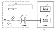
- FIG. 2 is a diagram showing a configuration example of the imaging unit 10 and the acquisition unit 110.
- the imaging unit 10 includes a wavelength separation mirror (dichroic mirror) 11, a first optical system 12, a first imaging device 13, a second optical system 14, and a second imaging device 15.
- the wavelength separation mirror 11 is an optical element that reflects light in a predetermined wavelength band and transmits light in different wavelength bands. For example, the wavelength separation mirror 11 reflects visible light and transmits infrared light. By using the wavelength separation mirror 11, the light from the object (subject) along the optical axis AX is separated into two directions.
- the visible light reflected by the wavelength separation mirror 11 enters the first image sensor 13 via the first optical system 12.
- the first optical system may include an unillustrated configuration such as a diaphragm and a mechanical shutter.
- the first imaging element 13 includes a photoelectric conversion element such as a CCD (Charge Coupled Device) and a CMOS (Complementary metal-oxide semiconductor), and outputs a visible light image signal that is a result of photoelectrically converting visible light.
- the visible light image signal here is an analog signal.
- the first image pickup device 13 is, for example, an image pickup device provided with a well-known Bayer array color filter. However, the first imaging element 13 may be an element using another color filter such as a complementary color type, or may be an imaging element of a different system.
- the acquisition unit 110 includes a first A/D conversion circuit 111 and a second A/D conversion circuit 112.
- the first A/D conversion circuit 111 performs A/D conversion processing on the visible light image signal from the first image sensor 13 and outputs visible light image data that is digital data.
- the visible light image data is, for example, RGB 3-channel image data.
- the second A/D conversion circuit 112 performs A/D conversion processing on the infrared light image signal from the second image sensor 15 and outputs infrared light image data that is digital data.
- the infrared light image data is, for example, 1-channel image data.
- the visible light image data and the infrared light image data which are digital data will be simply referred to as a visible light image and an infrared light image.
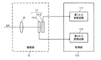
- infrared light is imaged by the second image sensor 15-2 relatively close to the third optical system 16.
- the second image sensor 15-2 outputs the infrared light image signal to the acquisition unit 110.
- visible light is imaged by the first image sensor 13-2 which is relatively far from the third optical system 16.
- the first image sensor 13-2 outputs the visible light image signal to the acquisition unit 110. Since a method of stacking a plurality of image pickup devices having different wavelength bands of an image pickup target in the optical axis direction is widely known, detailed description thereof will be omitted.
- the imaging unit 10 can image the same object coaxially with both visible light and infrared light. Therefore, it is possible to easily associate the position of the transparent object in the visible light image with the position of the transparent object in the infrared light image.
- the visible light image and the infrared light image are images having the same angle of view and the same number of pixels
- a given object is imaged at pixels at the same position in the visible light image and the infrared light image.
- the pixel position is information indicating the number of pixels in the horizontal direction and the number of pixels in the vertical direction with respect to the reference pixel.
- the position of the transparent object in the visible light image and the position of the transparent object in the infrared light image are equivalent. is there.
- the position of a given object in the visible light image can be associated with the position of the object in the infrared light image, even if there is a difference in the optical axis or the like. doing. Therefore, based on the position information of the transparent object in one of the visible light image and the infrared light image, the position information of the transparent object in the other can be specified.
- the position detection unit 124 may obtain the position information of both the visible light image and the infrared light image, or may obtain the position information of the transparent object in either one of them.
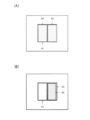
- FIGS. 5A and 5B are diagrams showing a glass door which is an example of a transparent object.
- FIG. 5A shows a state where the crow door is closed
- FIG. 5B shows a state where the glass door is open.
- two glasses A2 and A3 are arranged in the rectangular area A1.
- the glass door indicated by A2 among the two glasses moves in the horizontal direction to open and close the glass door.
- A1 and A2 In the closed state shown in FIG. 5A, two pieces of glass, A1 and A2, are arranged in almost the entire area of A1.
- the open state shown in FIG. 5B there is no glass in the left area of A1 and two glasses overlap in the right area.
- the area other than A1 is, for example, the wall surface of a building or the like, and here, in order to simplify the description, it is considered to be a uniform object having no unevenness and a small change in tint.
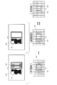
- FIG. 6 is a diagram showing an example of a visible light image and an infrared light image when the glass door is closed, and examples of the first to third feature amounts.
- B1 in FIG. 6 is an example of a visible light image
- B2 is an example of an infrared light image.
- B3 is an example of the first feature amount acquired by applying an edge extraction filter or the like to the visible light image of B1.
- the wall surface of the building is imaged in the area other than the glass, and the object such as B11 to B13 located behind the glass is imaged in the area where the glass is present. Since the imaged object is different between the glass and the other region, an edge is detected at the boundary. As a result, the value of the first feature amount increases at the boundary of the glass region (B31). Further, inside the region where the glass is present, the edges of the objects such as B11 to B13 that are present in the back of the glass are detected, so that the value of the first characteristic amount becomes somewhat large (B32).
- B5 is an example of the third feature amount that is the difference between the first feature amount and the second feature amount.
- the value of the third feature amount increases in B51, which is the region corresponding to glass.
- the same feature is detected in the visible light image and the infrared light image, so that the value of the third feature amount obtained by the difference is small.
- an edge is detected in both the first feature amount and the second feature amount, so that the edge is canceled.
- the values are canceled because the first feature amount and the second feature amount show similar tendencies.
- FIG. 6 shows an example in which the visible object has a low contrast, but the feature is canceled by the difference even when the visible object has some edge.
- the position detection unit 124 identifies a pixel whose third feature value is larger than a given threshold value as a pixel corresponding to a transparent object. For example, the position detection unit 124 determines the position and shape corresponding to the transparent object based on the region in which the pixels having the third feature amount value larger than the given threshold value are connected. The position detection unit 124 stores the detected position information of the transparent object in the storage unit 130.
- the information processing apparatus 100 may include a display unit (not shown), and the position detection unit 124 may output image data for presenting the detected position information of the transparent object to the display unit.
- the image data here is information in which information indicating the position of the transparent object is added to the visible light image, for example.
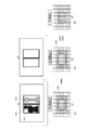
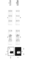
- FIG. 7 is a diagram showing an example of a visible light image and an infrared light image in a state where the glass door is open, and examples of the first to third feature amounts.
- C1 in FIG. 7 is an example of a visible light image
- C2 is an example of an infrared light image.
- C3 to C5 are examples of the first to third characteristic amounts.
- the conventional method is a method of determining the glass such as the shape and texture of an object based on the visible light image and the infrared light image and judging the glass from the feature. Therefore, if it is a low-contrast rectangular frame, it is difficult to separate it from other objects.
- infrared light images a glass, and visible light has a wavelength band in which an object in the back is imaged by transmitting the glass. The difference in the imaged object according to it is utilized. In a region where a transparent object is present, another object is imaged, and therefore the difference in characteristics becomes large even if the shape and texture are the same.
- the method of the present embodiment can detect a transparent object more accurately than the conventional method by using the third feature amount corresponding to the difference between the first feature amount and the second feature amount. Further, as described above with reference to FIGS. 6 and 7, it is possible to detect not only the presence or absence of the transparent object but also the position and shape. Further, as described above with reference to FIG. 7, since it is possible to prevent the area that has become the opening as a result of the movement of the transparent object from being erroneously detected as a transparent object, detection of a movable transparent object, specifically, It is also possible to judge whether the glass door or the like is opened or closed.
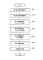
- the processing unit 120 extracts the third feature amount by calculating the difference between the first feature amount and the second feature amount (S105).
- the processing unit 120 detects the position of the transparent object based on the third characteristic amount (S106).
- the process of S106 is, for example, as described above, a process of comparing the value of the third feature amount with a given threshold value.
- the information processing device 100 of this embodiment includes the acquisition unit 110 and the processing unit 120.
- the acquisition unit 110 includes a first detection image in which a plurality of target objects including a first target object and a second target object that transmits visible light as compared with the first target object is captured by visible light, and a plurality of targets.
- a second detection image obtained by imaging an object with infrared light is acquired.
- the processing unit 120 obtains a first feature amount based on the first detection image, obtains a second feature amount based on the second detection image, and a feature corresponding to a difference between the first feature amount and the second feature amount.
- the amount is calculated as the third feature amount.
- the processing unit 120 detects the position of the second object in at least one of the first detection image and the second detection image based on the third feature amount.
- the third feature amount extraction unit 123 may obtain the ratio of the first feature amount and the second feature amount or information corresponding thereto as the feature amount corresponding to the difference.
- the position detection unit 124 determines that a pixel whose third characteristic amount, which is a ratio, deviates from 1 by a predetermined threshold value or more is a transparent object.
- the characteristic amount is obtained from each of the visible light image and the infrared light image, and the transparent object is detected using the characteristic amount based on the difference between them.
- the characteristics of the visible object in the visible light image, the characteristics of the transparent object in the visible light image, the characteristics of the visible object in the infrared light image, and the characteristics of the transparent object in the infrared light image are taken into consideration.
- the position of a highly transparent object can be detected.
- the contrast is information indicating the degree of difference in pixel value between a given pixel and pixels in the vicinity of the pixel.
- the above-mentioned edge is information indicating a region where the pixel value changes sharply, and is therefore included in the information indicating contrast.
- the contrast may be information based on the difference between the maximum value and the minimum value of pixel values in a predetermined area.
- the information indicating the contrast may be information whose value increases in a low contrast area.
- the method of this embodiment can be applied to a mobile body including the information processing apparatus 100 described above.
- the information processing device 100 can be incorporated in various moving bodies such as an automobile, an airplane, a motorcycle, a bicycle, a robot, or a ship.
- the moving body is a device/device that includes a drive mechanism such as an engine and a motor, a steering mechanism such as a steering wheel and a rudder, and various electronic devices, and moves on the ground, in the air, or at sea.
- the moving body includes, for example, the information processing device 100 and a control device 30 that controls the movement of the moving body.
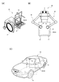
- 9A to 9C are diagrams showing an example of a moving body according to the present embodiment. Note that FIGS. 9A to 9C show an example in which the image capturing unit 10 is provided outside the information processing apparatus 100.
- the moving body is, for example, a wheelchair 20 that runs autonomously.
- the wheelchair 20 includes an imaging unit 10, an information processing device 100, and a control device 30.
- FIG. 9A illustrates an example in which the information processing device 100 and the control device 30 are integrally provided, but they may be provided separately.
- the information processing device 100 detects the position information of the transparent object by performing the above-mentioned processing.
- the control device 30 acquires the position information detected by the position detection unit 124 from the information processing device 100. Then, the control device 30 controls the drive unit for suppressing the collision between the wheelchair 20 and the transparent object based on the acquired position information of the transparent object.
- the drive unit here is, for example, a motor for rotating the wheels 21.
- Various methods are known for controlling a moving body to avoid a collision with an obstacle, and thus detailed description thereof will be omitted.
- the moving body may also be the robot shown in FIG. 9(B).
- the robot 40 includes the imaging unit 10 provided on the head, the information processing device 100 and the control device 30 built in the main body 41, the arm 43, the hand 45, and the wheels 47.
- the control device 30 controls the drive unit for suppressing the collision between the robot 40 and the transparent object based on the position information of the transparent object detected by the position detection unit 124.
- the control device 30 realizes a process of generating a movement path of the hand 45 that does not collide with the transparent object based on the position information of the transparent object, a movement of the hand 45 along the movement path, and an arm 43.
- the drive unit here is a motor for driving the arm 43 and the hand 45.
- the drive unit may include a motor for driving the wheels 47, and the control device 30 may perform wheel drive control for suppressing the collision between the robot 40 and the transparent object. Note that although a robot having an arm is illustrated in FIG. 9B, the method of this embodiment can be applied to robots of various modes.
- the third feature amount extraction unit 123 calculates the difference between the first feature amount and the second feature amount to calculate the third feature amount that is dominant in the transparent object. By using the third feature amount, it becomes possible to accurately detect the position of the transparent object.
- the fourth feature amount extraction unit 125 uses the third detection image, which is an image obtained by combining the first detection image (visible light image) and the second detection image (infrared light image), to determine the features of the visible object. The amount is detected as the fourth characteristic amount.
- the third detection image is, for example, an image in which the pixel value of the visible light image and the pixel value of the infrared light image are combined for each pixel.
- the fourth feature amount extraction unit 125 determines the pixel value of the R image corresponding to red light, the pixel value of the G image corresponding to green light, the pixel value of the B image corresponding to blue light, and the red value.
- the position detection unit 124 detects the position of the transparent object based on the third characteristic amount, and detects the position of the visible object based on the fourth characteristic amount. Thereby, the position detection unit 124 performs position detection by distinguishing both the transparent object and the visible object. Alternatively, the position detection unit 124 may perform position detection by distinguishing both the visible object and the transparent object by using the third feature amount and the fourth feature amount together.
- FIG. 11 is a flowchart illustrating the processing of this embodiment. 11.
- S201 to S205 of FIG. 11 are the same as S101 to S105 of FIG. 8, and the processing unit 120 obtains the third characteristic amount based on the first characteristic amount and the second characteristic amount. Further, the processing unit 120 extracts the fourth characteristic amount based on the visible light image and the infrared light image (S206). For example, as described above, the processing unit 120 obtains the third detection image by synthesizing the visible light image and the infrared light image, and extracts the fourth feature amount from the third detection image.
- the processing unit 120 detects the position of the transparent object and the position of the visible object based on the third feature amount and the fourth feature amount (S207).
- the process of S207 is, for example, a transparent object detection process by a comparison process of the value of the third feature amount with a given threshold value, and a visible object detection process by a comparison process of the value of the fourth feature amount value with another threshold value. including.
- the information processing apparatus 100 of this embodiment includes a storage unit 130 that stores a learned model.
- the learned model is machine-learned based on a data set in which the first learning image, the second learning image, the position information of the first target object and the position information of the second target object are associated with each other. ..
- the first learning image is a visible light image obtained by visualizing a plurality of objects including a first object (visible object) and a second object (transparent object).
- the second learning image is an infrared light image obtained by capturing the plurality of objects with infrared light.
- the processing unit 120 determines the position of the first object in at least one of the first detection image and the second detection image based on the first detection image, the second detection image, and the learned model. Both the positions of the second object are detected separately.
- machine learning By using machine learning in this way, it becomes possible to accurately detect the positions of visible and transparent objects.
- machine learning using a neural network will be described below, the method of the present embodiment is not limited to this.
- machine learning using another model such as SVM (support vector machine) may be performed, or machine learning using a method developed from various methods such as a neural network and SVM. May be performed.
- SVM support vector machine
- FIG. 12 is a diagram showing a configuration example of the learning device 200 of the present embodiment.
- the learning device 200 includes an acquisition unit 210 that acquires training data used for learning and a learning unit 220 that performs machine learning based on the training data.
- the acquisition unit 210 is, for example, a communication interface that acquires training data from another device. Alternatively, the acquisition unit 210 may acquire the training data held by the learning device 200.
- the learning device 200 includes a storage unit (not shown), and the acquisition unit 210 is an interface for reading training data from the storage unit.
- the learning in the present embodiment is, for example, supervised learning. Training data in supervised learning is a data set in which input data and correct answer labels are associated with each other.
- the learning unit 220 performs machine learning based on the training data acquired by the acquisition unit 210 and generates a learned model.
- the learning unit 220 of the present embodiment is configured by hardware including at least one of a circuit that processes a digital signal and a circuit that processes an analog signal, similar to the processing unit 120 of the information processing device 100.
- the hardware can be configured by one or a plurality of circuit devices mounted on a circuit board or one or a plurality of circuit elements.
- the learning device 200 may include a processor and a memory, and the learning unit 220 may be realized by various processors such as a CPU, GPU, and DSP.
- the memory may be a semiconductor memory, a register, a magnetic storage device, or an optical storage device.
- the acquisition unit 210 includes a visible light image obtained by imaging a plurality of objects including a first object and a second object that transmits visible light as compared with the first object with visible light.
- the learning unit 220 machine-learns the condition for detecting the first target object and the condition for detecting the position of the second target object in at least one of the visible light image and the infrared light image based on the data set.
- the user needs to manually set the filter characteristics for extracting the first feature amount, the second feature amount, and the fourth feature amount. Therefore, it is difficult to set a large number of filters that can efficiently extract the features of visible objects and transparent objects.
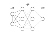
- FIG. 13 is a schematic diagram illustrating a neural network.
- the neural network has an input layer into which data is input, an intermediate layer that performs an operation based on the output from the input layer, and an output layer that outputs data based on the output from the intermediate layer.
- FIG. 13 illustrates a network in which the intermediate layer has two layers, the intermediate layer may have one layer or three or more layers. Further, the number of nodes (neurons) included in each layer is not limited to the example of FIG. 13, and various modifications can be implemented. In consideration of accuracy, it is desirable to use deep learning using a multilayer neural network for the learning of the present embodiment. In the narrow sense, the term "multilayer" means four or more layers.
- a node included in a given layer is combined with a node in an adjacent layer.
- a weight is set for each connection. For example, if each node in a given layer uses a fully connected neural network that is connected to all nodes in the next layer, the weight between the two layers is contained in the given layer. It is a set of values obtained by multiplying the number of nodes by the number of nodes included in the next layer. Each node multiplies the output of the preceding node by the weight and obtains the total value of the multiplication results. Further, each node adds the bias to the total value and applies the activation function to the addition result to obtain the output of the node.
- a ReLU function is known as an activation function. However, it is known that various functions can be used as the activation function, and a sigmoid function, a function obtained by improving the ReLU function, or another function may be used. Good.
- the output of the neural network is obtained by sequentially executing the above processing from the input layer to the output layer.
- Learning in the neural network is a process of determining an appropriate weight (including bias).
- Various methods such as the error back propagation method are known as specific learning methods, and they can be widely applied in the present embodiment. Since the error back propagation method is well known, detailed description will be omitted.
- the neural network is not limited to the configuration shown in FIG.
- a convolutional neural network (CNN: Convolutional Neural Network) may be used in the learning process and the inference process.
- the CNN includes, for example, a convolutional layer that performs a convolutional operation and a pooling layer.
- the convolutional layer is a layer that performs filtering.
- the pooling layer is a layer for performing pooling calculation for reducing the size in the vertical and horizontal directions.
- the weight in the CNN convolutional layer is a parameter of the filter. That is, learning in the CNN includes learning of filter characteristics used in the convolution calculation.
- FIG. 14 is a schematic diagram showing the configuration of the neural network in this embodiment.
- D1 of FIG. 14 is a block that receives a visible light image of 3 channels as an input and performs a process including a convolution operation to obtain the first feature amount.
- the first feature amount is, for example, a first feature map of 256 channels, which is obtained by performing 256 types of filter processing on the visible light image. Note that the number of channels of the feature map is not limited to 256, and various modifications can be implemented.
- D2 is a block that receives a 1-channel infrared light image as an input and performs a process including a convolution operation to obtain the second feature amount.
- the second feature amount is, for example, a 256-channel second feature map.
- D4 is a block that obtains a fourth feature amount by receiving a 4-channel image, which is a combination of the 3-channel visible light image and the 1-channel infrared light image, as an input and performing a process including a convolution operation.
- the fourth characteristic amount is, for example, a fourth characteristic map of 256 channels.
- FIG. 14 shows an example in which each block of D1, D2, and D4 includes one convolutional layer and one pooling layer. However, at least one of the convolutional layer and the pooling layer may be increased to two or more layers. Further, although omitted in FIG. 14, in each of the blocks D1, D2, and D4, for example, arithmetic processing for applying the activation function to the result of the convolution operation is performed.
- D5 is a block that detects the positions of a visible object and a transparent object based on a 512-channel feature map that is a combination of the third feature map and the fourth feature map.
- FIG. 14 shows an example in which the convolutional layer, the pooling layer, the upsampling layer, the convolutional layer, and the softmax layer are used for the 512-channel feature map. Is possible.
- the upsampling layer is a layer whose size is increased in the vertical direction and the horizontal direction, and may be referred to as an inverse pooling layer.
- the softmax layer is a layer that performs a calculation using a known softmax function.
- the output of the softmax layer is 3-channel image data.
- the image data of each channel is, for example, an image having the same number of pixels as the input visible light image and infrared light image.
- Each pixel of the first channel is numerical data of 0 or more and 1 or less indicating the probability that the pixel is a visible object.
- Each pixel of the second channel is numerical data of 0 or more and 1 or less indicating the probability that the pixel is a transparent object.
- Each pixel of the third channel is numerical data of 0 or more and 1 or less indicating the probability that the pixel is another object.
- the output of the neural network in this embodiment is the image data of the above three channels.
- the output of the neural network may be, for each pixel, image data in which the label representing the object having the highest probability and the probability thereof are associated with each other.
- the label representing the object having the highest probability and the probability thereof are associated with each other.
- there are three labels (0, 1, 2), 0 is a visible object, 1 is a transparent object, and 2 is another object.
- the probability of being a visible object is 0.3, the probability of being a transparent object is 0.5, and the probability of being another object is 0.2, the pixel in the output data has a transparent object. Is assigned a label of "1" and a probability of 0.5.
- the processing unit 120 may further classify four or more types of objects, such as classifying visible objects into people and roads.
- the training data in the present embodiment is a visible light image and an infrared light image captured coaxially, and position information associated with the images.
- the position information is, for example, information to which each label is attached to each pixel (0, 1, 2). As described above, in the label here, 0 represents a visible object, 1 represents a transparent object, and 2 represents other objects.
- input data is input to the neural network, and output data is obtained by performing forward calculation using the weights at that time.
- three input data are a three-channel visible light image, a one-channel infrared light image, a three-channel visible light image, and a four-channel image including a one-channel infrared light image.
- the output data obtained by the calculation in the forward direction is, for example, the output of the softmax layer described above. For one pixel, the probability p0 of being a visible object, the probability p1 of being a transparent object, and the probability p2(p0 of being another object).
- the learning unit 220 calculates an error function (loss function) based on the obtained output data and the correct answer label. If the correct label is 0, the pixel is a visible object, so the probability p0 of being a visible object should be 1, and the probability p1 of being a transparent object and the probability p2 of being another object should be 0. Therefore, the learning unit 220 calculates the degree of difference between 1 and p0 as an error function, and updates the weight in the direction in which the error becomes smaller.
- error functions are known, and they can be widely applied in this embodiment. Further, the weight is updated by using the error back propagation method, for example, but other methods may be used.
- the learning unit 220 may also calculate an error function based on the degree of difference between 0 and p1 and the degree of difference between 0 and p2, and update the weight.
- the visible light image and the infrared light image may be acquired by moving the moving body shown in FIGS. 9A to 9C in the learning stage.
- Training data is acquired by the user adding position information, which is a correct label, to the visible light image and the infrared light image.
- the learning device 200 shown in FIG. 12 may be integrated with the information processing device 100.
- the learning device 200 may be provided separately from the moving body and perform the learning process by acquiring a visible light image and an infrared light image from the moving body.
- the visible light image and the infrared light image may be acquired by using an imaging device having the same configuration as the imaging unit 10 without using the moving body itself.
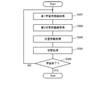
- FIG. 15 is a flowchart explaining the process in the learning device 200.
- the acquisition unit 210 of the learning device 200 acquires a first learning image that is a visible light image and a second learning image that is infrared light (S301, S302).
- the acquisition unit 210 also acquires position information corresponding to the first learning image and the second learning image (S303).
- the position information is information given by the user, for example, as described above.
- the learning unit 220 performs a learning process based on the acquired training data (S304).
- the process of S304 is a process in which each process of forward calculation, error function calculation, and weight updating based on the error function is performed once based on, for example, one data set.
- the learning unit 220 determines whether to end the machine learning (S305). For example, the learning unit 220 divides a large number of acquired data sets into training data and verification data. Then, the learning unit 220 determines the accuracy by performing the process using the verification data on the learned model acquired by performing the learning process based on the training data. Since the verification data is associated with the position information that is the correct answer label, the learning unit 220 can determine whether the position information detected based on the learned model is the correct answer.
- the learning unit 220 determines to end the learning when the accuracy rate of the verification data is equal to or higher than the predetermined threshold value (Yes in S305), and ends the process. Alternatively, the learning unit 220 may determine to end the learning when the processing shown in S304 is executed a predetermined number of times.
- the first feature amount in the present embodiment is the first feature map obtained by performing the convolution operation using the first filter on the first detection image.
- the second feature amount is a second feature map obtained by performing a convolution operation using the second filter on the second detection image.
- the first filter is a filter group used for calculation in the convolutional layer shown in D11 of FIG. 14, and the second filter is a filter group used for calculation in the convolutional layer shown in D21 of FIG.
- the filter characteristics of the first filter and the second filter are set by machine learning. In this way, by setting the filter characteristics using machine learning, it becomes possible to appropriately extract the features of each object included in the visible light image and the infrared light image. For example, as shown in FIG. 14, since it is possible to extract various features such as 256 channels, the accuracy of the position detection process based on the feature amount is improved.
- the fourth feature amount is a fourth feature map obtained by performing a convolution operation using the fourth filter on the first detection image and the second detection image. As described above, by performing the convolution operation using both the visible light image and the infrared light image as inputs, the fourth feature amount can be obtained. Further, the filter characteristics of the fourth filter are set by machine learning.
- the acquisition unit 210 of the learning device 200 images the plurality of objects including the first object and the second object with visible light, and the plurality of objects with infrared light.
- a data set in which the infrared light image and the position information of the second object in at least one of the visible light image and the infrared light image are associated with each other is acquired.
- the learning unit 220 machine-learns the condition for detecting the position of the second object in at least one of the visible light image and the infrared light image based on the data set. With this configuration, it is possible to accurately detect the position of the transparent object.
- a configuration example of the information processing apparatus 100 in this embodiment is the same as that in FIG. However, the storage unit 130 stores the learned model that is the result of the learning process in the learning unit 220.
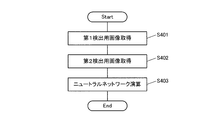
- FIG. 16 is a flowchart illustrating the inference process in the information processing device 100.
- the acquisition unit 110 acquires a first detection image that is a visible light image and a second detection image that is an infrared light image (S401, S402).
- the processing unit 120 operates in accordance with a command from the learned model stored in the storage unit 130 to perform a process of detecting the positions of the visible object and the transparent object in the visible light image and the infrared light image (S403).
- the processing unit 120 performs a neural network operation using three types of data of a visible light image alone, an infrared light image alone, and both a visible light image and an infrared light image as input data.
- the learned model is used as a program module that is a part of artificial intelligence software.
- the processing unit 120 outputs data representing the position information of the visible object and the position information of the transparent object in the input visible light image and infrared light image according to the instruction from the learned model stored in the storage unit 130.
- FIG. 17 is a diagram showing a configuration example of the processing unit 120 in the fourth embodiment.
- the processing unit 120 of the information processing device 100 includes a transparency score calculation unit 126 and a shape score calculation unit 127, respectively, instead of the third feature amount extraction unit 123 and the fourth feature amount extraction unit 125 in the second embodiment.
- the transmission score calculation unit 126 calculates, based on the first characteristic amount and the second characteristic amount, a transmission score indicating the degree of transmission of visible light of the target object for each target object in the visible light image and the infrared light image. ..
- a transmission score indicating the degree of transmission of visible light of the target object for each target object in the visible light image and the infrared light image.
- the transmission score in the present embodiment is not limited to information corresponding to the difference between the first characteristic amount and the second characteristic amount as long as it is information indicating the degree of transmission of visible light.
- the shape score calculation unit 127 determines the target object for each target object in the first detection image and the second detection image based on the third learning image in which the first detection image and the second detection image are combined. A shape score indicating the shape is calculated.
- the third detection image is generated, for example, by adding the luminances of the first detection image and the second detection image for each pixel.
- the third image for detection has high robustness against light and darkness of the shooting scene, and information regarding the shape can be stably acquired.
- the shape score calculation unit calculates a shape score that indicates only the shape of the object that does not depend on the degree of transmission of visible light.
- the position detection unit 124 performs position detection by distinguishing both a transparent object and a visible object based on the transmission score and the shape score. For example, the position detection unit 124 determines that the target object is a transparent object when the transparency score is a relatively high value and the shape score is a value indicating a predetermined shape corresponding to the transparent object.
- the processing unit 120 of the information processing apparatus 100 regarding the plurality of objects captured in the first detection image and the second detection image, based on the first feature amount and the second feature amount.
- a transmission score indicating the degree of transmission of visible light is calculated.
- the processing unit 120 also calculates a shape score indicating the shapes of the plurality of objects captured in the first detection image and the second detection image, based on the first detection image and the second detection image. Then, the processing unit 120 distinguishes and detects both the position of the first object and the position of the second object in at least one of the first detection image and the second detection image based on the transmission score and the shape score. To do.
- the transmission score is calculated by individually obtaining the first feature amount and the second feature amount, and the shape score is calculated using both the visible light image and the infrared light image. Since each score can be calculated based on an appropriate input, it becomes possible to accurately detect a visible object and a transparent object.
- machine learning may be applied to the method of calculating the transparency score and the shape score.
- the storage unit 130 of the information processing device 100 stores the learned model.
- the learned model includes a first learning image obtained by imaging a plurality of objects with visible light, a second learning image obtained by imaging a plurality of objects with infrared light, a first learning image and a second learning image.
- Machine learning is performed based on a data set in which the position information of the first object and the position information of the second object in at least one of the images are associated with each other.
- the processing unit 120 calculates the shape score and the transmission score based on the first detection image, the second detection image, and the learned model, and then calculates the first object based on the transmission score and the shape score. And the position of the second object are detected separately.
- FIG. 18 is a schematic diagram showing the configuration of the neural network in this embodiment.
- E1 and E2 in FIG. 18 are similar to D1 and D2 in FIG. E3 is a block for obtaining a transparency score based on the first feature map and the second feature map.
- the calculation for the first characteristic amount and the second characteristic amount is not limited to the calculation based on the difference.
- a transmission score is calculated by performing a convolution operation on a 512-channel feature map that is a combination of a first feature map and a second feature map that are 256-channel feature maps.
- the operation here is not limited to the operation using the convolutional layer, and for example, the operation by the fully connected layer or the like may be used, or another operation may be used.
- the calculation of the transparency score based on the first feature amount and the second feature amount can be the target of the learning process.
- the transparency score is not limited to the feature quantity corresponding to the difference, unlike the third feature quantity.
- E4 is a block that obtains a shape score by receiving a 4-channel image that is a combination of a 3-channel visible light image and a 1-channel infrared light image as an input and performing processing including a convolution operation.
- the configuration of E4 is similar to D4 of FIG.
- E5 is a block that detects the position of a visible object and a transparent object based on the shape score and the transparency score.
- FIG. 18 as in D5 of FIG. 14, an example in which the convolutional layer, the pooling layer, the upsampling layer, the convolutional layer, and the softmax layer are used for the calculation is shown. It is possible.
- the weights at E1 to E3 are values for outputting an appropriate transmission score
- the weight at E4 is an appropriate shape score.
- the position of the object is determined based on the shape score and the transparency score by using the configuration of FIG. 18 in which three types of inputs are input, each input is processed independently, and then the processing results are combined. It is possible to build a trained model that does the detection.
- FIG. 19 is a schematic diagram for explaining the transparency score calculation process.
- F1 is a visible light image
- F11 represents a region in which a transparent object exists
- F12 represents a visible object in the back of the transparent object.
- F2 is an infrared light image, and the transparent object shown in F21 is imaged, and the visible object corresponding to F12 is not imaged.
- F3 represents the pixel value of the area corresponding to F13 in the visible light image.
- F13 is the boundary between F12 which is a visible object and the background. Since the background is bright here, the pixel values in the left and center columns are small, and the pixel values in the right column are large. Note that the pixel values in FIG. 19 and FIG. 20 described later show values that are normalized so as to fall within the range of ⁇ 1 to +1.
- a score value F7 which is relatively large to some extent, is output by performing an operation in which the filter having the characteristic shown in F5 is applied to the region of F3.
- F5 is one of the filters whose characteristics are set as a result of learning, and is, for example, a filter for extracting vertical edges.
- F4 represents the pixel value of the area corresponding to F23 in the infrared light image.
- F23 corresponds to a transparent object and thus has low contrast.
- the pixel values are almost the same in the entire area of F4. Therefore, a score value F8 having a large absolute value and a negative value is output by performing an operation using a filter having the characteristic shown in F6.
- F6 is one of the filters whose characteristics are set as a result of learning, and is, for example, a filter for extracting a flat region.
- the processing unit 120 can obtain the transparency score by subtracting F8 from F7.
- how to use the first feature amount and the second feature amount to obtain the transmission score is also a target of machine learning. Therefore, the transmission score can be calculated by a flexible process according to the set filter characteristic.
- FIG. 20 is a schematic diagram illustrating the shape score calculation process.
- G1 in FIG. 20 is a visible light image, and G11 represents a visible object.
- G2 is an infrared light image, and the same visible object G21 as G11 is imaged.
- G3 represents the pixel value of the area corresponding to G12 in the visible light image.
- G12 is the boundary between G11 which is a visible object and the background. Since the background is bright here, the pixel values in the left and center columns are small, and the pixel values in the right column are large. Therefore, a score value G7, which is relatively large to some extent, is output by performing an operation in which a filter having the characteristic shown in G5 is applied.
- G5 is one of the filters whose characteristics are set as a result of learning, and is, for example, a filter for extracting vertical edges.
- G4 represents the pixel value of the area corresponding to G22 in the infrared light image.
- G22 is a boundary between G21 which is a visible object and the background.
- a visible object such as a person serves as a heat source, and thus is imaged brighter than the background area. Therefore, the pixel values in the left and center columns are large, and the pixel values in the right column are small. Therefore, a score value G8, which is relatively large to some extent, is output by performing an operation using a filter having the characteristics shown in G6.
- G6 is one of the filters whose characteristics are set as a result of learning, and is, for example, a filter for extracting vertical edges. Note that G5 and G6 have different gradient directions.
- Shape score is calculated by convolutional operation for 4-channel images.
- the shape score is a feature map including the result of adding G7 and G8.
- information in which the value increases in the area corresponding to the edge of the object is calculated as the shape score.
Landscapes
- Engineering & Computer Science (AREA)
- Multimedia (AREA)
- Signal Processing (AREA)
- Computer Vision & Pattern Recognition (AREA)
- Physics & Mathematics (AREA)
- General Physics & Mathematics (AREA)
- Theoretical Computer Science (AREA)
- Human Computer Interaction (AREA)
- Image Analysis (AREA)
- Image Processing (AREA)
- Studio Devices (AREA)
Abstract
Dispositif de traitement d'informations (100) comprenant une unité d'acquisition (110) et une unité de commande (120). L'unité d'acquisition (110) acquiert : une première image de détection par capture d'une image d'une pluralité d'objets comprenant un premier objet et un second objet qui est plus perméable à la lumière visible que le premier objet ; et une seconde image de détection qui capture une image d'une pluralité d'objets à l'aide d'une lumière infrarouge. L'unité de traitement (120) détermine une première quantité de caractéristiques sur la base de la première image de détection, détermine une seconde quantité de caractéristiques sur la base de la seconde image de détection, et calcule une troisième quantité de caractéristique correspondant à la différence entre la première quantité de caractéristique et la seconde quantité de caractéristique. L'unité de traitement (120) détecte la position du second objet dans la première image de détection et/ou la seconde image de détection sur la base de la troisième quantité de caractéristiques.
Priority Applications (3)
| Application Number | Priority Date | Filing Date | Title |
|---|---|---|---|
| PCT/JP2019/007653 WO2020174623A1 (fr) | 2019-02-27 | 2019-02-27 | Dispositif de traitement d'informations, corps mobile et dispositif d'apprentissage |
| JP2021501466A JP7142851B2 (ja) | 2019-02-27 | 2019-02-27 | 情報処理装置、移動体及び学習装置 |
| US17/184,929 US20210201533A1 (en) | 2019-02-27 | 2021-02-25 | Information processing device, mobile body, and learning device |
Applications Claiming Priority (1)
| Application Number | Priority Date | Filing Date | Title |
|---|---|---|---|
| PCT/JP2019/007653 WO2020174623A1 (fr) | 2019-02-27 | 2019-02-27 | Dispositif de traitement d'informations, corps mobile et dispositif d'apprentissage |
Related Child Applications (1)
| Application Number | Title | Priority Date | Filing Date |
|---|---|---|---|
| US17/184,929 Continuation US20210201533A1 (en) | 2019-02-27 | 2021-02-25 | Information processing device, mobile body, and learning device |
Publications (1)
| Publication Number | Publication Date |
|---|---|
| WO2020174623A1 true WO2020174623A1 (fr) | 2020-09-03 |
Family
ID=72239630
Family Applications (1)
| Application Number | Title | Priority Date | Filing Date |
|---|---|---|---|
| PCT/JP2019/007653 Ceased WO2020174623A1 (fr) | 2019-02-27 | 2019-02-27 | Dispositif de traitement d'informations, corps mobile et dispositif d'apprentissage |
Country Status (3)
| Country | Link |
|---|---|
| US (1) | US20210201533A1 (fr) |
| JP (1) | JP7142851B2 (fr) |
| WO (1) | WO2020174623A1 (fr) |
Cited By (1)
| Publication number | Priority date | Publication date | Assignee | Title |
|---|---|---|---|---|
| JP2025068385A (ja) * | 2023-10-16 | 2025-04-28 | トヨタ自動車株式会社 | 情報処理装置、情報処理システム、および、情報処理方法 |
Families Citing this family (2)
| Publication number | Priority date | Publication date | Assignee | Title |
|---|---|---|---|---|
| CN113570574B (zh) * | 2021-07-28 | 2023-12-01 | 北京精英系统科技有限公司 | 一种场景特征检测的装置、搜索的装置及搜索的方法 |
| CN113869510B (zh) * | 2021-09-24 | 2025-09-16 | 上海商汤智能科技有限公司 | 网络训练、解锁、对象追踪方法、装置、设备及存储介质 |
Citations (3)
| Publication number | Priority date | Publication date | Assignee | Title |
|---|---|---|---|---|
| JP2017191470A (ja) * | 2016-04-13 | 2017-10-19 | キヤノン株式会社 | 処理装置、処理方法、及びプログラム |
| JP2017220923A (ja) * | 2016-06-07 | 2017-12-14 | パナソニックIpマネジメント株式会社 | 画像生成装置、画像生成方法、およびプログラム |
| WO2018235777A1 (fr) * | 2017-06-20 | 2018-12-27 | 国立大学法人静岡大学 | Dispositif de traitement de données d'image, système de culture de plantes et procédé de traitement de données d'image |
Family Cites Families (8)
| Publication number | Priority date | Publication date | Assignee | Title |
|---|---|---|---|---|
| US7642949B2 (en) * | 2006-08-03 | 2010-01-05 | Lockheed Martin Corporation | Illumination source for millimeter wave imaging |
| JP6176191B2 (ja) * | 2014-06-19 | 2017-08-09 | 株式会社Jvcケンウッド | 撮像装置及び赤外線画像生成方法 |
| JP6657646B2 (ja) * | 2015-08-06 | 2020-03-04 | オムロン株式会社 | 障害物検知装置、障害物検知方法、および障害物検知プログラム |
| WO2019059120A1 (fr) * | 2017-09-22 | 2019-03-28 | 日本電気株式会社 | Dispositif de traitement d'informations, système de traitement d'informations, procédé de traitement d'informations et support d'enregistrement |
| US10504240B1 (en) * | 2017-10-18 | 2019-12-10 | Amazon Technologies, Inc. | Daytime heatmap for night vision detection |
| KR102476757B1 (ko) * | 2017-12-21 | 2022-12-09 | 삼성전자주식회사 | 반사를 검출하는 장치 및 방법 |
| US11094074B2 (en) * | 2019-07-22 | 2021-08-17 | Microsoft Technology Licensing, Llc | Identification of transparent objects from image discrepancies |
| CN113240741B (zh) * | 2021-05-06 | 2023-04-07 | 青岛小鸟看看科技有限公司 | 基于图像差异的透明物体追踪方法、系统 |
-
2019
- 2019-02-27 JP JP2021501466A patent/JP7142851B2/ja active Active
- 2019-02-27 WO PCT/JP2019/007653 patent/WO2020174623A1/fr not_active Ceased
-
2021
- 2021-02-25 US US17/184,929 patent/US20210201533A1/en not_active Abandoned
Patent Citations (3)
| Publication number | Priority date | Publication date | Assignee | Title |
|---|---|---|---|---|
| JP2017191470A (ja) * | 2016-04-13 | 2017-10-19 | キヤノン株式会社 | 処理装置、処理方法、及びプログラム |
| JP2017220923A (ja) * | 2016-06-07 | 2017-12-14 | パナソニックIpマネジメント株式会社 | 画像生成装置、画像生成方法、およびプログラム |
| WO2018235777A1 (fr) * | 2017-06-20 | 2018-12-27 | 国立大学法人静岡大学 | Dispositif de traitement de données d'image, système de culture de plantes et procédé de traitement de données d'image |
Non-Patent Citations (1)
| Title |
|---|
| TOMOYUKI TAKAHATA , ISAO SHIMOYAMA: "Drip-proof visible light/far infrared coaxial imaging system", THE 36TH ANNUAL CONFERENCE OF THE ROBOTICS SOCIETY OF JAPAN - NIHON ROBOTTO GAKKAI GAKUJUTSU KŌENKAI ; 36 (KASUGAI) : 2018.09.04-07, 4 September 2018 (2018-09-04), XP009523361 * |
Cited By (1)
| Publication number | Priority date | Publication date | Assignee | Title |
|---|---|---|---|---|
| JP2025068385A (ja) * | 2023-10-16 | 2025-04-28 | トヨタ自動車株式会社 | 情報処理装置、情報処理システム、および、情報処理方法 |
Also Published As
| Publication number | Publication date |
|---|---|
| JPWO2020174623A1 (ja) | 2021-09-30 |
| US20210201533A1 (en) | 2021-07-01 |
| JP7142851B2 (ja) | 2022-09-28 |
Similar Documents
| Publication | Publication Date | Title |
|---|---|---|
| KR102574141B1 (ko) | 이미지 디스플레이 방법 및 디바이스 | |
| KR102821467B1 (ko) | 이미지 수정 기법들 | |
| US12347114B2 (en) | Object segmentation and feature tracking | |
| US10728436B2 (en) | Optical detection apparatus and methods | |
| WO2021164234A1 (fr) | Procédé de traitement d'image et dispositif de traitement d'image | |
| TW202226141A (zh) | 圖像去霧方法和使用圖像去霧方法的圖像去霧設備 | |
| CN119487825A (zh) | 图像中的对象移除 | |
| JP2017005389A (ja) | 画像認識装置、画像認識方法及びプログラム | |
| JP7142851B2 (ja) | 情報処理装置、移動体及び学習装置 | |
| US11385526B2 (en) | Method of processing image based on artificial intelligence and image processing device performing the same | |
| CN116917954A (zh) | 图像检测方法、装置和电子设备 | |
| KR20240144123A (ko) | 높은 동적 범위 이미징을 위한 모션 기반 노출 제어 | |
| US20250104379A1 (en) | Efficiently processing image data based on a region of interest | |
| CN118575484A (zh) | 多传感器成像颜色校正 | |
| CN114693542A (zh) | 图像去雾方法和使用图像去雾方法的图像去雾设备 | |
| CN113066019A (zh) | 一种图像增强方法及相关装置 | |
| CN107925719B (zh) | 摄像装置、摄像方法、及非暂时性记录介质 | |
| CN113723409A (zh) | 门控成像语义分割方法和装置 | |
| CN113852773A (zh) | 图像处理设备和方法、摄像系统、移动体及存储介质 | |
| US20250045868A1 (en) | Efficient image-data processing | |
| CN121127883A (zh) | 使用关键帧和依赖帧神经网络的低光图像增强 | |
| US20240054659A1 (en) | Object detection in dynamic lighting conditions | |
| CN120500710A (zh) | 使用登记图像的面部表情识别 | |
| WO2025064159A1 (fr) | Génération de contenu d'image | |
| CN121074833A (zh) | 基于人工智能的通用车辆全彩夜视辅助驾驶方法及系统 |
Legal Events
| Date | Code | Title | Description |
|---|---|---|---|
| 121 | Ep: the epo has been informed by wipo that ep was designated in this application |
Ref document number: 19916670 Country of ref document: EP Kind code of ref document: A1 |
|
| ENP | Entry into the national phase |
Ref document number: 2021501466 Country of ref document: JP Kind code of ref document: A |
|
| NENP | Non-entry into the national phase |
Ref country code: DE |
|
| 122 | Ep: pct application non-entry in european phase |
Ref document number: 19916670 Country of ref document: EP Kind code of ref document: A1 |