WO2020174675A1 - Ensemble chargeur/dispositif électronique, et système de communication - Google Patents
Ensemble chargeur/dispositif électronique, et système de communication Download PDFInfo
- Publication number
- WO2020174675A1 WO2020174675A1 PCT/JP2019/007908 JP2019007908W WO2020174675A1 WO 2020174675 A1 WO2020174675 A1 WO 2020174675A1 JP 2019007908 W JP2019007908 W JP 2019007908W WO 2020174675 A1 WO2020174675 A1 WO 2020174675A1
- Authority
- WO
- WIPO (PCT)
- Prior art keywords
- charger
- magnet
- connector
- clip
- electronic device
- Prior art date
- Legal status (The legal status is an assumption and is not a legal conclusion. Google has not performed a legal analysis and makes no representation as to the accuracy of the status listed.)
- Ceased
Links
Images









Classifications
-
- G—PHYSICS
- G09—EDUCATION; CRYPTOGRAPHY; DISPLAY; ADVERTISING; SEALS
- G09B—EDUCATIONAL OR DEMONSTRATION APPLIANCES; APPLIANCES FOR TEACHING, OR COMMUNICATING WITH, THE BLIND, DEAF OR MUTE; MODELS; PLANETARIA; GLOBES; MAPS; DIAGRAMS
- G09B21/00—Teaching, or communicating with, the blind, deaf or mute
- G09B21/009—Teaching or communicating with deaf persons
-
- H—ELECTRICITY
- H02—GENERATION; CONVERSION OR DISTRIBUTION OF ELECTRIC POWER
- H02J—ELECTRIC POWER NETWORKS; CIRCUIT ARRANGEMENTS OR SYSTEMS FOR SUPPLYING OR DISTRIBUTING ELECTRIC POWER; SYSTEMS FOR STORING ELECTRIC ENERGY
- H02J7/00—Circuit arrangements for charging or discharging batteries or for supplying loads from batteries
- H02J7/70—Circuit arrangements for charging or discharging batteries or for supplying loads from batteries characterised by the mechanical construction
- H02J7/751—Circuit arrangements for charging or discharging batteries or for supplying loads from batteries characterised by the mechanical construction concerning the insertion or the connection of the batteries
-
- H—ELECTRICITY
- H01—ELECTRIC ELEMENTS
- H01M—PROCESSES OR MEANS, e.g. BATTERIES, FOR THE DIRECT CONVERSION OF CHEMICAL ENERGY INTO ELECTRICAL ENERGY
- H01M10/00—Secondary cells; Manufacture thereof
- H01M10/42—Methods or arrangements for servicing or maintenance of secondary cells or secondary half-cells
- H01M10/46—Accumulators structurally combined with charging apparatus
-
- H—ELECTRICITY
- H02—GENERATION; CONVERSION OR DISTRIBUTION OF ELECTRIC POWER
- H02J—ELECTRIC POWER NETWORKS; CIRCUIT ARRANGEMENTS OR SYSTEMS FOR SUPPLYING OR DISTRIBUTING ELECTRIC POWER; SYSTEMS FOR STORING ELECTRIC ENERGY
- H02J7/00—Circuit arrangements for charging or discharging batteries or for supplying loads from batteries
- H02J7/70—Circuit arrangements for charging or discharging batteries or for supplying loads from batteries characterised by the mechanical construction
-
- H—ELECTRICITY
- H01—ELECTRIC ELEMENTS
- H01M—PROCESSES OR MEANS, e.g. BATTERIES, FOR THE DIRECT CONVERSION OF CHEMICAL ENERGY INTO ELECTRICAL ENERGY
- H01M2220/00—Batteries for particular applications
- H01M2220/30—Batteries in portable systems, e.g. mobile phone, laptop
-
- H—ELECTRICITY
- H04—ELECTRIC COMMUNICATION TECHNIQUE
- H04R—LOUDSPEAKERS, MICROPHONES, GRAMOPHONE PICK-UPS OR LIKE ACOUSTIC ELECTROMECHANICAL TRANSDUCERS; ELECTRIC HEARING AIDS; PUBLIC ADDRESS SYSTEMS
- H04R1/00—Details of transducers, loudspeakers or microphones
- H04R1/08—Mouthpieces; Microphones; Attachments therefor
-
- Y—GENERAL TAGGING OF NEW TECHNOLOGICAL DEVELOPMENTS; GENERAL TAGGING OF CROSS-SECTIONAL TECHNOLOGIES SPANNING OVER SEVERAL SECTIONS OF THE IPC; TECHNICAL SUBJECTS COVERED BY FORMER USPC CROSS-REFERENCE ART COLLECTIONS [XRACs] AND DIGESTS
- Y02—TECHNOLOGIES OR APPLICATIONS FOR MITIGATION OR ADAPTATION AGAINST CLIMATE CHANGE
- Y02E—REDUCTION OF GREENHOUSE GAS [GHG] EMISSIONS, RELATED TO ENERGY GENERATION, TRANSMISSION OR DISTRIBUTION
- Y02E60/00—Enabling technologies; Technologies with a potential or indirect contribution to GHG emissions mitigation
- Y02E60/10—Energy storage using batteries
Definitions
- the technology disclosed in the present application relates to a set of an electronic device and a charger, and a communication system.
- the connector of the electronic device is connected to the charging connector of the charger by combining the electronic device with the charger. Then, electric power is supplied from the charger to the battery of the electronic device via the connector and the charging connector, and the battery is charged (see, for example, Patent Documents 1 and 2).
- Patent Documents 3 and 4 and Non-Patent Document 1 there is one that has a function of converting a received signal into vibration, sound, light, or the like (for example, Patent Documents 3 and 4 and Non-Patent Document 1).
- the set of the electronic device and the charger is required to be easily combined with the regular position of the charger.
- the technology disclosed in the present application aims, as one aspect, to allow an electronic device to be easily combined with a charger.
- a set of an electronic device and a charger includes an electronic device and a charger to which the electronic device is combined.
- the electronic device has a main body, a clip, and a magnet.
- the main body portion has a battery and a connector electrically connected to the battery.
- the clip extends along the body.
- the magnet is provided on the clip.
- the charger has a charging connector, a recess, and a suction magnet.
- the charging connector is arranged at a position to be connected to the connector when the electronic device is combined with the charger.
- the recess is formed at a position to accommodate the clip when the electronic device is combined with the charger.
- the attraction magnet is provided at a portion of the recess facing the magnet, and an attraction force is generated between the attraction magnet and the magnet.
- an electronic device can be easily combined with a charger.
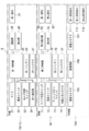
- FIG. 1 is a block diagram of the communication system of FIG. 1.
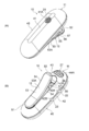
- FIG. 1 is a perspective view of the cordless handset of FIG.
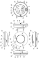
- FIG. 3 is a six-sided view of the child device of FIG. 1.
- FIG. 9 is a sectional view taken along line F9-F9 of FIG. 8. It is a perspective view of the main
- FIG. 3 is a six-sided view of the parent device of FIG. 1.
- FIG. 12 is a sectional view taken along line F12-F12 of FIG. It is a perspective view of the charger of FIG. It is a 6th figure of the charger of FIG.
- FIG. 15 is a sectional view taken along line F15-F15 of FIG. It is sectional drawing which shows the state which combined the subunit
- FIG. 15 is a sectional view taken along line F17-F17 of FIG. It is sectional drawing which shows the state which combined the main
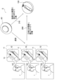
- FIG. 1 shows an outline of a communication system S according to this embodiment.
- the communication system S includes a plurality of slaves 10, a master 60, and a charger 100.
- Each of the plurality of slaves 10 is an example of an “electronic device”.
- the plurality of child devices 10 are used by the first user 1 who is, for example, a deaf person, and the parent device 60 is used by the second user.
- the child device 10 has a main body 11 and a clip 12, and is fixed to the hair by sandwiching the hair between the main body 11 and the clip 12.
- the parent device 60 can communicate with the plurality of child devices 10, and when signals are transmitted from the parent device 60 to the plurality of child devices 10, the plurality of child devices 10 generate vibration or light according to the received signals. appear.
- the plurality of child devices 10 and the parent device 60 are selectively combined with the charger 100 and charged by the charger 100.
- the combination of each of the plurality of child devices 10 and the charger 100 forms a child device and charger set 200
- the combination of the parent device 60 and the charger 100 forms a parent device and charger set 210.
- the set 200 of the child device and the charger is an example of “a set of the electronic device and the charger”.
- the master device 60 is provided with a push button switch 73.
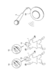
- the push button switch 73 When the push button switch 73 is pressed by the second user 2 in accordance with the rhythm sound, a signal corresponding to the rhythm sound is transmitted from the master device 60 to the plurality of slave devices 10. Then, each slave 10 generates vibration or light in accordance with the rhythm sound, and the rhythm sound can be taught to each first user 1.
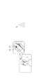
- the microphone 3 can be connected to the master device 60.
- a rhythm sound is input to the microphone 3 connected to the master device 60
- a signal corresponding to the rhythm sound is transmitted from the master device 60 to the plurality of slave devices 10.
- each slave 10 generates vibration or light in accordance with the rhythm sound, and the rhythm sound can be taught to each first user 1.
- the smart phone 4 can be connected to the master device 60.
- a signal corresponding to the rhythm sound is transmitted from the master device 60 to the plurality of slave devices 10. Then, each slave 10 generates vibration or light in accordance with the rhythm sound, and the rhythm sound can be taught to each first user 1 who is looking at the screen of the smartphone 5.
- the above-described child device 10 has a parent device communication mode and a microphone input mode.
- the slave 10 communicates with the master 60 as described above.
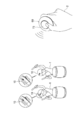
- FIG. 5 shows a usage example in which the child device 10 is used alone.
- a microphone 21 is mounted on the mobile device 10.
- the handset 10 When the sound 6 is input to the microphone 21 in the microphone input mode in the microphone input mode, the handset 10 generates vibration or light in response to the sound 6, and can teach the first user 1 the sound 6.
- the handset 10 can be switched to a mode for generating only vibration, a mode for generating only light, or a mode for generating both vibration and light.
- FIG. 6 is a block diagram of the communication system S.
- the main body 11 of the child device 10 includes a microphone 21, a power switch 22, a mode switch 23, a first communication device 24, a first controller 25, a first battery 26, and a first connector 27.
- the microphone 21, the power switch 22, the mode changeover switch 23, the first communication device 24, the vibrator 28, and the light emitter 29 are electrically connected to the first controller 25 and the first battery 26, respectively.
- the first connector 27 is electrically connected to the first battery 26.
- the first connector 27 is an example of a “connector”, the first battery 26 is an example of a “battery”, and the first magnet 31 is an example of a “magnet”.
- the master device 60 includes a microphone volume switch 71, a power switch 72, a push button switch 73, an external input connector 74, a second controller 75, a second battery 76, a second connector 77, a second communication device 78, a light emitter 79, And a pair of second magnets 82.
- the microphone volume switch 71, the power switch 72, the push button switch 73, the external input connector 74, the second communication device 78, and the light emitter 79 are electrically connected to the second controller 75 and the second battery 76.
- the second connector 77 is electrically connected to the second battery 76.
- the charger 100 has a power supply connector 105, a power supply circuit 106, a charging connector 107, a first attraction magnet 111, and a pair of second attraction magnets 112.
- the power supply connector 105 and the charging connector 107 are electrically connected to the power supply circuit 106, respectively.
- FIGS. 7 and 8 The child device 10 is shown in FIGS. 7 and 8.
- 7A is a perspective view of the child device 10 viewed from the front side
- FIG. 7B is a perspective view of the child device 10 viewed from the back side.
- 8A is a front view of the child device 10
- FIG. 8B is a left side view of the child device 10
- FIG. 8C is a right side view of the child device 10
- FIG. 8E is a bottom view of the child device 10
- FIG. 8F is a rear view of the child device 10.
- the main body 11 of the slave 10 has a housing 40.
- the housing 40 is formed in a substantially ellipsoidal shape with the vertical direction of the slave 10 as the length direction.
- An opening 41A is formed in the front wall 41 of the housing 40, and the microphone 21 is provided inside the opening 41A.
- a pair of openings 42A and 42B are formed in the left side wall 42 of the housing 40, the power switch 22 is provided inside the opening 42A, and the mode changeover switch 23 is provided inside the opening 42B. Is provided.
- the rear wall 43 of the housing 40 is formed with a first engagement recess 44 that is recessed toward the front side of the slave 10.
- the first engagement recess 44 is an example of an “engagement recess”.
- An opening 44A is formed in the bottom wall of the first engagement recess 44, and the first connector 27 is provided inside the opening 44A.
- the clip 12 is formed into a substantially oval shape when viewed from the rear side of the child device 10, and extends along the length direction of the main body 11.
- One end in the length direction of the clip 12 is the first end 51, and the other end in the length direction of the clip 12, that is, the end located on the opposite side to the first end in the length direction of the clip 12.
- the part is the second end 52.
- a support portion 55 that rotatably supports the clip 12 is provided on the back wall 43 of the housing 40.
- the support portion 55 has a support shaft 56 extending in the left-right direction of the main body portion 11, and the clip 12 is rotatable around the support shaft 56.
- a torsion spring 57 is attached to the support shaft 56, and the torsion spring 57 urges the clip 12 in the direction in which the first end 51 abuts the rear wall 43.
- the elastic force of the torsion spring 57 maintains the first end portion 51 in contact with the back wall 43.
- a convex portion 51A is formed on the first end portion 51, and specifically, the convex portion 51A is brought into contact with the back wall 43.
- the second end portion 52 is located on the side opposite to the first end portion 51 with respect to the support portion 55, and the second end portion 52 is located on the rear wall when the first end portion 51 is in contact with the rear wall 43. It is separated from 43.
- the first connector 27 is arranged on the extension of the second end 52 side of the clip 12 when viewed from the rear side of the slave 10 (see FIG. 8F). That is, when the second end portion 52 side of the clip 12 is extended in the length direction of the clip 12 when viewed from the rear side of the child device 10, the first connector 27 is arranged at a position overlapping the extended portion. Has been done.
- the back surface side of the child device 10 is an example of “a side in which an electronic device is combined with a charger”.
- the pair of edges connecting the left and right ends of the first end portion 51 and the left and right ends of the second end portion 52 are the side portions 54 on both sides of the clip 12.
- the side portions 54 on both sides of the clip 12 extend in parallel along the length direction of the clip 12 when the slave 10 is viewed from the rear.
- FIG. 9 shows a sectional view taken along line F9-F9 of FIG.
- the child device 10 has a substrate 20.
- the microphone 21, the power switch 22, the mode switch 23, the first communication device 24, the first controller 25, the first connector 27, the vibrator 28, and the light emitter 29 (see FIGS. 8) is implemented.
- the board 20 and the first battery 26 are housed in a housing 40.
- the board 20 is arranged with the front-back direction of the slave 10 as the plate thickness direction, and the first battery 26 is arranged between the board 20 and the back wall 43.
- a portion of the clip 12 between the first end portion 51 and the second end portion 52 is a first shape portion 53, and the first shape portion 53 is from the first end portion 51 side to the second end portion 52 side. It has such a shape that it gradually moves away from the main body portion 11 as it goes toward.
- the shape of the first shape portion 53 is a warp shape that gradually goes away from the main body portion 11 from the first end portion 51 side toward the second end portion 52 side. ..
- the apex of the curved portion 53A of the first shape portion 53 is located at the center of the first shape portion 53 in the length direction.
- the portion between the first end portion 51 and the curved portion 53A of the clip 12 and the portion between the curved portion 53A and the second end portion 52 of the clip 12 are both planar (in a side view). (Straight line).
- the first magnet 31 is provided on the first shape portion 53.
- the first magnet 31 is formed in a flat plate shape. More specifically, the first magnet 31 is arranged closer to the second end 52 side than the apex of the curved portion 53A that is the central portion in the lengthwise direction of the first shaped portion 53.
- the first magnet 31 is arranged on the side of the first end 51 with respect to the support 55. That is, the first magnet 31 is arranged between the apex of the curved portion 53A of the first shape portion 53 and the support portion 55.
- the first magnet 31 is provided along the shape of the first shape portion 53.
- the first magnet 31 is arranged so as to be inclined with respect to the back wall 43 so as to gradually move away from the back wall 43 from the central portion side in the longitudinal direction of the first shape portion 53 toward the support portion 55 side.
- the clip 12 is formed with a concave portion 33 that opens toward the main body portion 11, and the first magnet 31 is fitted into the concave portion 33.
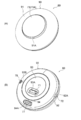
- the parent device 60 is shown in FIGS. 10 and 11.
- 10A is a perspective view of the parent device 60 seen from the front side
- FIG. 10B is a perspective view of the parent device 60 seen from the back side.
- 11A is a front view of the master device 60
- FIG. 11B is a left side view of the master device 60
- FIG. 11C is a right side view of the master device 60
- FIG. FIG. 11E is a bottom view of the master device 60
- FIG. 11F is a rear view of the master device 60.
- the parent device 60 has a housing 90.
- the housing 90 is formed into a substantially disc shape with the front-back direction of the parent device 60 as the thickness direction.
- an opening 91A is formed in the front wall 91 of the housing 90, and the button cover 73A of the push button switch 73 is provided inside the opening 91A.
- the button cover 73A is formed in a circular shape when the parent device 60 is viewed from the front.
- An opening 92A and an opening 92B are formed in the peripheral wall portion 92 of the housing 90, a power switch 72 is provided inside the opening 92A, and an external input connector 74 is provided inside the opening 92B. Is provided.
- An opening 93A and an opening 93B are formed in the back wall 93 of the housing 90, a microphone volume switch 71 is provided inside the opening 93A, and a light emitter 79 is provided inside the opening 93B. Is provided.
- a second engagement recess 94 that is recessed toward the front side of the parent device 60 is formed on the back wall 93 of the housing 90.
- An opening 94A is formed in the bottom wall of the second engagement recess 94, and a second connector 77 is provided inside the opening 94A.
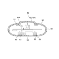
- FIG. 12 shows a sectional view taken along line F12-F12 of FIG.
- the parent device 60 has a substrate 70.
- the microphone volume switch 71, the power switch 72, the push button switch 73, the external input connector 74, the second controller 75, the second connector 77, the second communication device 78, and the light emitter 79 are mounted on the board 70.
- the board 70 and the second battery 76 are housed in a housing 90.
- the board 70 is arranged with the front-back direction of the parent device 60 as the plate thickness direction.
- the pair of second magnets 82 are arranged side by side in the left-right direction of the parent device 60.
- the pair of second magnets 82 are provided on the back wall 93.
- the back wall 93 is formed with a pair of concave portions 83 that open to the front wall 91 side, and the pair of second magnets 82 is fitted into the pair of concave portions 83, respectively.
- FIGS. 13 and 14 The charger 100 is shown in FIGS. 13 and 14.
- FIG. 13A is a perspective view of the charger 100 seen from the front side
- FIG. 13B is a perspective view of the charger 100 seen from the back side.
- 14A is a front view of the charger 100
- FIG. 14B is a left side view of the charger 100
- FIG. 14C is a right side view of the charger 100
- FIG. 14E is a bottom view of the charger 100
- FIG. 14F is a rear view of the charger 100.
- the charger 100 has a housing 120.
- the housing 120 is formed in a substantially disc shape with the front-back direction of the charger 100 as the thickness direction.
- the front wall 121 of the housing 120 is formed with a recess 132 that is recessed toward the back side of the charger 100.
- the front wall 121 in which the recess 132 is formed is an example of “a wall facing the main body of the charger”.
- the recess 132 is formed in the center of the front wall 121, for example.
- the recess 132 is formed in a substantially oval shape extending in the up-down direction of the parent device 60 when the parent device 60 is viewed from the front.
- the clip 12 (see FIGS. 7 to 9) is accommodated in the recess 132.
- the recess 132 is formed in a similar shape slightly larger than the clip 12 described above when the parent device 60 is viewed from the front.
- the side surfaces 134 on both sides of the recess 132 are formed along the side portions 54 (see FIGS. 7 to 9) on both sides of the clip 12 described above.
- an engaging convex portion 124 that is convex toward the front side of the parent device 60 is formed.
- An opening 124A is formed in the ceiling wall of the engaging projection 124, and the charging connector 107 is provided inside the opening 124A.
- the charging connector 107 is connected to the first connector 27 (see FIGS. 7 to 9) when the slave unit 10 is combined with the charger 100, and is connected to the second connector 27 when the master unit 60 is combined with the charger 100. It is arranged at a position where it is connected to the connector 77 (see FIGS. 10 to 12).
- the engagement convex portion 124 has a shape that engages with the first engagement concave portion 44 (see FIGS. 7 to 9) and the second engagement concave portion 94 (see FIGS. 10 to 12), respectively.
- the charging connector 107 is arranged on an extension of the recess 132 in the lengthwise direction when viewed from the front side of the charger 100 (see FIG. 14(A)). That is, when the second connector 77 side of the recess 132 is extended in the length direction of the recess 132 when viewed from the front side of the charger 100, the second connector 77 is arranged at a position overlapping the extended portion. ing.
- An opening 122A is formed in the peripheral wall 122 of the housing 120, and the power supply connector 105 is provided inside the opening 122A.
- a power cable (not shown) is connected to the power connector 105.
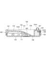
- FIG. 15 is a sectional view taken along line F15-F15 of FIG. Further, FIG. 16 shows a state in which the child device 10 of FIG. 1 is combined with the charger 100.
- the first connector 27 and the charging connector 107 are arranged so as to be connected along the direction in which the child device 10 is combined with the charger 100. That is, the first connector 27 is arranged so as to face the charger 100 side, and the charging connector 107 is arranged so as to face the slave unit 10 side.
- the charging connector 107 projects from the front wall 121 by being provided on the engaging convex portion 124. That is, the charging connector 107 has the protruding height H with respect to the front wall 121 of the charger 100.
- the protrusion height H is between the second end portion 52 of the clip 12 and the second facing portion 142 of the bottom wall portion 133 facing the second end portion 52 of the clip 12 in the state where the first connector 27 and the charging connector 107 are connected. It is set to a height that creates a gap.
- the recess 132 is formed at a position to accommodate the clip 12 when the slave 10 is combined with the charger 100.
- the recess 132 has a bottom wall 133.
- the bottom wall portion 133 includes a first facing portion 141, a second facing portion 142, and a second shaped portion 143, which face the first end portion 51, the second end portion 52, and the first shaped portion 53 of the clip 12, respectively.
- the first facing portion 141 is one end portion in the length direction of the bottom wall portion 133
- the second facing portion 142 is the other end portion in the length direction of the bottom wall portion 133.
- the first facing portion 141 is located on the same side as the first end portion 51 of the clip 12 and faces the first end portion 51.
- the second facing portion 142 is located on the same side as the second end portion 52 of the clip 12 and faces the second end portion 52.
- the second shape portion 143 is a portion of the bottom wall portion 133 between the first facing portion 141 and the second facing portion 142.
- the second shape portion 143 has a shape that gradually moves away from the front wall 121 of the charger 100 from the first facing portion 141 side toward the second facing portion 142 side.
- the shape of the second shape portion 143 is gradually separated from the front wall 121 as it goes from the first facing portion 141 side toward the second facing portion 142 side, like the first shaped portion 53. It is warped to warp.
- the apex of the curved portion 143A of the second shape portion 143 is located at the center in the lengthwise direction of the second shape portion 143.
- the portion between the first facing portion 141 and the curved portion 143A in the bottom wall portion 133 and the portion between the curved portion 143A and the second facing portion 142 in the bottom wall portion 133 are both planar as an example. It is formed in a straight line when viewed from the side.
- the first shape portion 53 formed on the clip 12 described above has a warp shape that is warped along the second shape portion 143.
- the first attraction magnet 111 is an example of “attraction magnet”, and is provided in the second shape portion 143.
- two magnets are superposed, and the two magnets form the first attraction magnet 111.
- the two magnets forming the first attraction magnet 111 are each formed in a flat plate shape.
- the first attraction magnet 111 is provided at a portion of the bottom wall portion 133 facing the first magnet 31.
- the first attraction magnet 111 is arranged so that an attraction force is generated between the first attraction magnet 111 and the first magnet 31. That is, the first attraction magnet 111 is arranged such that the magnetic pole on the first magnet 31 side of the first attraction magnet 111 is different from the magnetic pole on the first attraction magnet 111 side of the first magnet 31.
- the first attraction magnet 111 is arranged closer to the second facing portion 142 than the apex of the curved portion 143A, which is the central portion in the lengthwise direction of the second shape portion 143.
- the first attraction magnet 111 is arranged on the first facing portion 141 side with respect to the facing portion with the support portion 55. That is, the first attraction magnet 111 is arranged between the apex of the curved portion 143A, which is the central portion in the lengthwise direction of the second shape portion 143, and the facing portion of the support portion 55.
- the first attraction magnet 111 is provided along the shape of the second shape portion 143. As a result, the first attraction magnet 111 is gradually moved away from the front wall 121 from the central portion side in the lengthwise direction of the second shape portion 143 toward the opposite side to the support portion 55, with respect to the front wall 121. It is arranged to be inclined.
- the bottom wall portion 133 is formed with a concave portion 113 that opens to the side opposite to the front wall 121.
- the first magnet of the first attraction magnet 111 is fitted in the concave portion 113, and the second magnet of the first attraction magnet 111 is fixed to the first magnet.
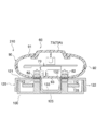
- FIG. 17 is a sectional view taken along line F17-F17 of FIG. Further, FIG. 18 shows a state in which the parent device 60 of FIG. 1 is combined with the charger 100.
- the pair of second attraction magnets 112 are arranged side by side in the left-right direction of the charger 100.
- the pair of second attraction magnets 112 are provided at the portions of the front wall 121 facing the pair of second magnets 82, respectively.
- the pair of second attraction magnets 112 are provided on both sides of the recess 132 in the lateral width direction.
- the pair of second magnets 82 described above are respectively provided in the facing portions of the recesses 132 on both sides in the lateral width direction.
- the front wall 121 is formed with a pair of concave portions 114 that open to the rear wall 123 side, and the pair of second attraction magnets 112 are fitted into the pair of concave portions 114, respectively.
- the pair of second attraction magnets 112 are arranged so that an attraction force is generated between the pair of second attraction magnets 112. That is, each second attraction magnet 112 is arranged such that the magnetic pole on the second magnet 82 side of the second attraction magnet 112 is different from the magnetic pole on the second attraction magnet 112 side of the second magnet 82.
- the charger 100 also has a weight 135 (weight).
- the weight 135 is arranged with the front-back direction of the charger 100 as the plate thickness direction.
- the weight 135 is housed in the housing 120.
- the weight 135 is formed in a substantially C-shape when the charger 100 is viewed from the front.
- a groove 136 extending in the up-down direction of the charger 100 is formed in the center of the weight 135, and a recess 132 is arranged inside the groove 136.
- FIG. 19 shows how the child device 10 of FIG. 1 is combined with the charger 100.
- the cordless handset 10 is gradually brought closer to the charger 100 from diagonally above the front of the charger 100 and is combined with the charger 100.
- the clip 12 is inserted into the recess 132 while the second end portion 52 of the clip 12 is in sliding contact with the bottom wall portion 133 of the recess 132.
- the clip 12 is provided with the first magnet 31, and at the portion of the bottom wall portion 133 of the recess 132 facing the first magnet 31, the first attraction is generated between the first magnet 31 and the first magnet 31.
- a magnet 111 is provided. Therefore, as the clip 12 is inserted into the recess 132, the clip 12 is sucked into the recess 132 by the attraction force generated between the first magnet 31 and the first attraction magnet 111. Then, the clip 12 is housed in the concave portion 132, and the cordless handset 10 is combined with the regular position of the charger 100.
- the main body 11 of the child device 10 is provided with a first connector 27, and the charger 100 is provided with a charging connector 107.
- the charging connector 107 is arranged at a position to be connected to the first connector 27 when the cordless handset 10 is combined with the charger 100. Therefore, the handset 10 is assembled to the regular position of the charger 100, and at the same time, the first connector 27 is connected to the charging connector 107. Then, by connecting the first connector 27 to the charging connector 107, electric power is supplied from the charger 100 to the first battery 26 via the first connector 27 and the charging connector 107, and the first battery 26 is charged. ..
- the clip 12 is generated by the attraction force generated between the first magnet 31 provided on the clip 12 and the first attraction magnet 111 provided on the bottom wall portion 133 of the recess 132. Can be sucked into the recess 132. Therefore, in order to smoothly charge the first battery 26 of the child device 10, the child device 10 can be easily combined with the regular position of the charger 100.
- the clip 12 has the first shape portion 53, and the bottom wall portion 133 of the recess 132 has the second shape portion 143 facing the first shape portion 53.
- the second shape portion 143 has a shape that gradually moves away from the front wall 121 from the first facing portion 141 side toward the second facing portion 142 side.
- the first magnet 31 and the first attraction magnet 111 are provided in the first shaped portion 53 and the second shaped portion 143, respectively. Therefore, by the attraction force generated between the first magnet 31 and the first attraction magnet 111, the clip 12 is sucked into the recess 132 while the second end 52 of the clip 12 is brought into sliding contact with the bottom wall portion 133 of the recess 132. be able to. Thereby, the handset 10 can be combined with the charger 100 in a stable posture.
- the second shape portion 143 has a warp shape that gradually goes away from the front wall 121 from the first facing portion 141 side toward the second facing portion 142 side. Therefore, when the second end portion 52 of the clip 12 makes sliding contact with the bottom wall portion 133 of the recess 132 and the second end portion 52 passes over the apex of the curved portion 53A of the second shape portion 143, the bottom wall portion 133. The amount of movement of the clip 12 to the side increases. As a result, the clip 12 can be sucked into the recess 132 more vigorously, so that the cordless handset 10 can be more accurately combined with the regular position of the charger 100.
- the first attraction magnet 111 is arranged closer to the second facing portion 142 than the apex of the curved portion 143A, which is the central portion in the lengthwise direction of the second shape portion 143. Therefore, when the second end portion 52 of the clip 12 passes over the apex of the curved portion 53A of the second shape portion 143, the attraction force generated between the first magnet 31 and the first attraction magnet 111 is increased, so that the clip 12 is further extended. It can be sucked into the recess 132 more vigorously.
- the side portions 54 (see FIG. 8) on both sides of the clip 12 extend in parallel along the length direction of the clip 12, and the side surfaces 134 (see FIG. 14) on both sides of the recess 132 are on both sides of the clip 12. It is formed along the side portion 54 of the. Therefore, the side surfaces 134 on both sides of the recess 132 serve as guides for guiding the side portions 54 on both sides of the clip 12, so that the clip 12 can be inserted straight into the recess 132 along the length direction of the clip 12. it can. As a result, it is possible to prevent the handset 10 from being displaced when the handset 10 is assembled to the charger 100.
- the first connector 27 is arranged on an extension of the clip 12 on the side of the second end 52 of the clip 12 when viewed from the side where the cordless handset 10 is combined with the charger 100 (see FIG. 8F). Therefore, the first connector 27 can be smoothly connected to the charging connector 107 as the clip 12 is inserted straight into the recess 132 along the length direction of the clip 12.
- the main body portion 11 of the child device 10 is formed with the first engagement concave portion 44
- the charger 100 is formed with the engagement convex portion 124 having a shape that engages with the first engagement concave portion 44.
- the first connector 27 is provided in the first engagement concave portion 44
- the charging connector 107 is provided in the engagement convex portion 124. Therefore, by engaging the engagement protrusion 124 with the first engagement recess 44, the first connector 27 can be guided to the charging connector 107. Thereby, the first connector 27 can be smoothly connected to the charging connector 107.
- the charging connector 107 provided on the engaging convex portion 124 has a protruding height H (see FIG. 16) with respect to the front wall 121 of the charger 100.
- the protrusion height H is between the second end portion 52 of the clip 12 and the second facing portion 142 of the bottom wall portion 133 facing the second end portion 52 of the clip 12 in the state where the first connector 27 and the charging connector 107 are connected. It is set to a height that creates a gap. Therefore, when the slave 10 and the charger 100 are placed horizontally, the first connector 27 can be connected to the charging connector 107 with the weight of the slave 10 added to the first connector 27. As a result, the first connector 27 can be reliably connected to the charging connector 107.
- the first magnet 31 is arranged on the side of the first end portion 51 with respect to the support portion 55. Therefore, for example, compared with the case where the first magnet 31 is arranged on the second end 52 side with respect to the support 55, a gap between the second end 52 and the main body 11 can be secured. This can prevent the first magnet 31 and the main body 11 from interfering with each other when the clip 12 is rotated, and can secure the rotation amount of the clip 12.
- FIG. 20 shows how the parent device 60 of FIG. 1 is combined with the charger 100.
- the parent device 60 is gradually brought closer to the charger 100 from above the front of the charger 100 and is combined with the charger 100.
- the parent device 60 has a second magnet 82, and a second attraction magnet 112 that produces an attraction force between the second magnet 82 and the second magnet 82 is provided at a portion of the charger 100 facing the second magnet 82. Has been. Therefore, when the master device 60 is brought closer to the charger 100, the master device 60 is sucked into the charger 100 by the attraction force generated between the second magnet 82 and the second attraction magnet 112, and the master device 60 is charged. Combined in 100 regular positions.
- the master device 60 has a second connector 77 (see FIGS. 10 and 11), and the charger 100 is provided with a charging connector 107 (see FIGS. 13 and 14).
- Charging connector 107 is arranged at a position where it is connected to second connector 77 when master device 60 is combined with charger 100. Therefore, at the same time that the master device 60 is assembled in the regular position of the charger 100, the second connector 77 is connected to the charging connector 107. Then, by connecting the second connector 77 to the charging connector 107, electric power is supplied from the charger 100 to the second battery 76 via the second connector 77 and the charging connector 107, and the second battery 76 is charged. ..
- the attraction force generated between the second magnet 82 of the parent device 60 and the second attraction magnet 112 provided at the portion of the charger 100 facing the second magnet 82 is reduced by the attraction force.
- the parent device 60 can be sucked into the charger 100. Therefore, in order to smoothly charge the second battery 76 of the parent device 60, the parent device 60 can be easily combined with the regular position of the charger 100.
- the pair of second magnets 82 of the parent device 60 are respectively provided at the portions facing the portions on both sides in the lateral width direction of the recess 132, and the pair of second attracting magnets 112 of the charger 100 have the lateral width of the recess 132. They are provided on both sides in the direction. Therefore, for example, as compared with the case where the number of the second magnets 82 and the number of the second suction magnets 112 is one, respectively, by the attraction force generated between the pair of second magnets 82 and the pair of second suction magnets 112, The base unit 60 can be combined with the charger 100 in a stable posture.
- a second engagement recess 94 (see FIGS. 10 and 11) is formed in the master device 60, and an engagement protrusion 124 having a shape that engages with the second engagement recess 94 is provided in the charger 100. (See FIGS. 13 and 14) are formed.
- the second engaging recess 94 is provided with the second connector 77, and the engaging protruding portion 124 is provided with the charging connector 107. Therefore, by engaging the engagement protrusion 124 with the second engagement recess 94, the second connector 77 can be guided to the charging connector 107. As a result, the second connector 77 can be smoothly connected to the charging connector 107.
- the communication system S includes a plurality of slaves 10, but the number of slaves 10 in the communication system S may be one. Further, the communication system S includes one master device 60 and one charger 100, but the number of master devices 60 and chargers 100 in the communication system S may be plural.
- the electronic device combined with the charger 100 is the slave unit 10, but the electronic device combined with the charger 100 in the set of the electronic device and the charger is not limited to the slave unit 10 and various wears having a clip. It may be an electronic device such as a ring device.
- the number of the first magnets 31 in the slave 10 is one, the number of the first magnets 31 in the slave 10 may be plural. Further, the number of the first attraction magnets 111 in the charger 100 may be plural depending on the number of the first magnets 31 in the slave 10.
- the number of the second magnets 82 in the parent device 60 is two, the number of the second magnets 82 in the parent device 60 may be one or three or more. Further, the number of the second attraction magnets 112 in the charger 100 may be one or three or more depending on the number of the second magnets 82 in the parent device 60.
- the first magnet 31 is arranged on the side of the first end 51 with respect to the support 55, but may be arranged on the side of the second end 52 with respect to the support 55.
- the pair of second magnets 82 are respectively arranged at the facing portions of the recesses 132 on both sides in the lateral width direction, but the second magnets 82 may be arranged anywhere on the parent device 60. Further, the pair of second attracting magnets 112 are respectively disposed on both sides of the recess 132 in the lateral width direction, but may be disposed anywhere on the charger 100 as long as they are portions facing the second magnet 82.
- the first attraction magnet 111 is arranged closer to the second facing portion 142 than the apex of the curved portion 143A, which is the central portion in the lengthwise direction of the second shape portion 143.
- the first attraction magnet 111 may be arranged anywhere in the bottom wall portion 133 as long as it is a portion of the bottom wall portion 133 facing the first attraction magnet 111.
- the first attraction magnet 111 is provided on the bottom wall portion 133, it may be provided on the sidewall portion of the recess 132.
- the first shape portion 53 has a warp shape in which a curved portion 53A is formed in the center portion in the length direction, but has a warp shape in which a bent portion is formed in the center portion in the length direction. May be.
- first shape portion 53 preferably has a warp shape that warps along the second shape portion 143, but may have a shape other than that.
- the second shape portion 143 has a warp shape in which a curved portion 53A is formed in the center portion in the length direction, but has a warp shape in which a bent portion is formed in the center portion in the length direction. May be.
- the portion between the first facing portion 141 and the curved portion 143A in the bottom wall portion 133 and the portion between the curved portion 143A and the second facing portion 142 in the bottom wall portion 133 are both examples. Although it is formed in a planar shape (linear shape in a side view), any of them may be formed in a curved shape.
- the second shape portion 143 has a warp shape that is gradually warped away from the front wall 121 from the first facing portion 141 side toward the second facing portion 142 side.
- the second shape portion 143 is formed in a generally planar shape (linear shape in a side view), and gradually moves away from the front wall 121 from the first facing portion 141 side toward the second facing portion 142 side. Thus, it may be inclined with respect to the front wall 121.
- the second shape portion 143 preferably has a shape that gradually moves away from the front wall 121 as it goes from the first facing portion 141 side toward the second facing portion 142 side, but it may have a shape other than that. Good.
- the side portions 54 on both sides of the clip 12 extend in parallel along the length direction of the clip 12, but for example, the width becomes narrower from the first end portion 51 side toward the second end portion 52 side. It may be formed in a tapered shape.
- the side surfaces 134 on both sides of the concave portion 132 are formed along the side portions 54 on both sides of the clip 12, but the width thereof becomes narrower from the first facing portion 141 side toward the second facing portion 142 side. It may be formed in a tapered shape.
- the clip 12 is rotatably supported by the main body 11 by a support portion 55 provided between the first end portion 51 and the second end portion 52. It may be provided at the second end 52.
- the first connector 27 is preferably arranged on an extension of the clip 12 on the side of the second end 52 of the clip 12 when viewed from the side where the cordless handset 10 is combined with the charger 100. It may be arranged at a position deviating from the extension on the end 52 side.
- the projecting height H of the charging connector 107 is preferably a height that causes a gap between the second end portion 52 and the second facing portion 142 when the first connector 27 and the charging connector 107 are connected. Is set to However, the protruding height H of the charging connector 107 may be set to a height at which the second end portion 52 and the second facing portion 142 are brought into contact with each other when the first connector 27 and the charging connector 107 are connected. Good.
- the modified examples that can be combined may be appropriately combined.
Landscapes
- Engineering & Computer Science (AREA)
- Manufacturing & Machinery (AREA)
- Chemical & Material Sciences (AREA)
- Chemical Kinetics & Catalysis (AREA)
- Electrochemistry (AREA)
- General Chemical & Material Sciences (AREA)
- Power Engineering (AREA)
- Audiology, Speech & Language Pathology (AREA)
- Health & Medical Sciences (AREA)
- General Health & Medical Sciences (AREA)
- Business, Economics & Management (AREA)
- Physics & Mathematics (AREA)
- Educational Administration (AREA)
- Educational Technology (AREA)
- General Physics & Mathematics (AREA)
- Theoretical Computer Science (AREA)
- Charge And Discharge Circuits For Batteries Or The Like (AREA)
Abstract
Priority Applications (5)
| Application Number | Priority Date | Filing Date | Title |
|---|---|---|---|
| EP19917320.4A EP3934052B1 (fr) | 2019-02-28 | 2019-02-28 | Ensemble chargeur/dispositif électronique, et système de communication |
| PCT/JP2019/007908 WO2020174675A1 (fr) | 2019-02-28 | 2019-02-28 | Ensemble chargeur/dispositif électronique, et système de communication |
| CN201980092070.5A CN113424390B (zh) | 2019-02-28 | 2019-02-28 | 电子设备与充电器的套件以及通信系统 |
| JP2019532820A JP6575737B1 (ja) | 2019-02-28 | 2019-02-28 | 電子機器と充電器のセット、及び通信システム |
| US17/394,654 US11837898B2 (en) | 2019-02-28 | 2021-08-05 | Electronic device-to-charger set, and communication system |
Applications Claiming Priority (1)
| Application Number | Priority Date | Filing Date | Title |
|---|---|---|---|
| PCT/JP2019/007908 WO2020174675A1 (fr) | 2019-02-28 | 2019-02-28 | Ensemble chargeur/dispositif électronique, et système de communication |
Related Child Applications (1)
| Application Number | Title | Priority Date | Filing Date |
|---|---|---|---|
| US17/394,654 Continuation US11837898B2 (en) | 2019-02-28 | 2021-08-05 | Electronic device-to-charger set, and communication system |
Publications (1)
| Publication Number | Publication Date |
|---|---|
| WO2020174675A1 true WO2020174675A1 (fr) | 2020-09-03 |
Family
ID=67982840
Family Applications (1)
| Application Number | Title | Priority Date | Filing Date |
|---|---|---|---|
| PCT/JP2019/007908 Ceased WO2020174675A1 (fr) | 2019-02-28 | 2019-02-28 | Ensemble chargeur/dispositif électronique, et système de communication |
Country Status (5)
| Country | Link |
|---|---|
| US (1) | US11837898B2 (fr) |
| EP (1) | EP3934052B1 (fr) |
| JP (1) | JP6575737B1 (fr) |
| CN (1) | CN113424390B (fr) |
| WO (1) | WO2020174675A1 (fr) |
Cited By (2)
| Publication number | Priority date | Publication date | Assignee | Title |
|---|---|---|---|---|
| JPWO2022070994A1 (fr) * | 2020-09-29 | 2022-04-07 | ||
| US11941182B2 (en) | 2020-09-29 | 2024-03-26 | Nintendo Co., Ltd. | Electronic apparatus |
Families Citing this family (10)
| Publication number | Priority date | Publication date | Assignee | Title |
|---|---|---|---|---|
| USD974330S1 (en) * | 2019-06-26 | 2023-01-03 | Catalyst Lifestyle Limited | Case for electronic device |
| USD1003284S1 (en) | 2019-10-23 | 2023-10-31 | Catalyst Lifestyle Limited | Sleeve for electronic device |
| USD1003884S1 (en) | 2019-12-13 | 2023-11-07 | Catalyst Lifestyle Limited | Sleeve for electronic device |
| USD954716S1 (en) | 2020-01-20 | 2022-06-14 | Catalyst Lifestyle Limited | Sleeve for electronic device |
| USD954063S1 (en) | 2020-01-20 | 2022-06-07 | Catalyst Lifestyle Limited | Sleeve for electronic device |
| USD954715S1 (en) | 2020-01-20 | 2022-06-14 | Catalyst Lifestyle Limited | Sleeve for electronic device |
| USD974758S1 (en) | 2020-02-26 | 2023-01-10 | Catalyst Lifestyle Limited | Sleeve for electronic device |
| USD986713S1 (en) | 2020-02-28 | 2023-05-23 | Catalyst Lifestyle Limited | Case for electronic device |
| USD969815S1 (en) | 2021-03-24 | 2022-11-15 | Catalyst Lifestyle Limited | Case for electronic device |
| USD994327S1 (en) | 2021-03-26 | 2023-08-08 | Catalyst Lifestyle Limited | Case for electronic device |
Citations (5)
| Publication number | Priority date | Publication date | Assignee | Title |
|---|---|---|---|---|
| JPS6177644U (fr) * | 1984-10-29 | 1986-05-24 | ||
| JPS62186374U (fr) * | 1986-05-16 | 1987-11-27 | ||
| JP2000166960A (ja) | 1998-12-08 | 2000-06-20 | Kyoto Process Kogeisha:Kk | 聴力障害者用音声感知装置 |
| JP2012130227A (ja) | 2010-12-17 | 2012-07-05 | Denso Wave Inc | 携帯機器と充電器のセット |
| JP2018182635A (ja) * | 2017-04-19 | 2018-11-15 | レノボ・シンガポール・プライベート・リミテッド | ドッキング装置及び電子機器システム |
Family Cites Families (10)
| Publication number | Priority date | Publication date | Assignee | Title |
|---|---|---|---|---|
| JPH0655200U (ja) | 1993-01-08 | 1994-07-26 | 宏二 杉原 | 音声信号を光に変換させる装置 |
| JP2013038920A (ja) | 2011-08-08 | 2013-02-21 | Denso Wave Inc | 携帯機器、充電器、及び、これらのセット |
| CN203747471U (zh) * | 2014-03-10 | 2014-07-30 | 惠州Tcl移动通信有限公司 | 一种磁铁防呆结构 |
| WO2016069652A1 (fr) * | 2014-10-27 | 2016-05-06 | Zachary Pierce | Système et procédé de fixation d'accessoires de dispositif cellulaire |
| CN108496345B (zh) * | 2016-01-19 | 2021-02-26 | 株式会社精好 | 笔型呼入呼出通话装置 |
| CN205942412U (zh) * | 2016-06-08 | 2017-02-08 | 科沃斯机器人股份有限公司 | 母子机协同工作系统 |
| KR20180047492A (ko) * | 2016-10-31 | 2018-05-10 | 디큐브랩 주식회사 | 브로치형 스마트 히어링장치 |
| JP2018098571A (ja) * | 2016-12-09 | 2018-06-21 | パナソニックIpマネジメント株式会社 | ウェアラブルカメラ |
| JP6855031B2 (ja) * | 2017-07-13 | 2021-04-07 | 日本圧着端子製造株式会社 | Icカード、および、icカード充電用コネクタ |
| US10916955B1 (en) * | 2017-10-16 | 2021-02-09 | S & N Technologies, LLC | Modular multi-functional conference wearable system |
-
2019
- 2019-02-28 JP JP2019532820A patent/JP6575737B1/ja active Active
- 2019-02-28 EP EP19917320.4A patent/EP3934052B1/fr active Active
- 2019-02-28 CN CN201980092070.5A patent/CN113424390B/zh active Active
- 2019-02-28 WO PCT/JP2019/007908 patent/WO2020174675A1/fr not_active Ceased
-
2021
- 2021-08-05 US US17/394,654 patent/US11837898B2/en active Active
Patent Citations (5)
| Publication number | Priority date | Publication date | Assignee | Title |
|---|---|---|---|---|
| JPS6177644U (fr) * | 1984-10-29 | 1986-05-24 | ||
| JPS62186374U (fr) * | 1986-05-16 | 1987-11-27 | ||
| JP2000166960A (ja) | 1998-12-08 | 2000-06-20 | Kyoto Process Kogeisha:Kk | 聴力障害者用音声感知装置 |
| JP2012130227A (ja) | 2010-12-17 | 2012-07-05 | Denso Wave Inc | 携帯機器と充電器のセット |
| JP2018182635A (ja) * | 2017-04-19 | 2018-11-15 | レノボ・シンガポール・プライベート・リミテッド | ドッキング装置及び電子機器システム |
Non-Patent Citations (2)
| Title |
|---|
| A NEW USER INTERFACE FOR EXPERIENCING SOUND THROUGH HAIR (JAPANESE, 21 February 2019 (2019-02-21), Retrieved from the Internet <URL:http://ontenna.jp> |
| See also references of EP3934052A4 |
Cited By (6)
| Publication number | Priority date | Publication date | Assignee | Title |
|---|---|---|---|---|
| JPWO2022070994A1 (fr) * | 2020-09-29 | 2022-04-07 | ||
| WO2022070994A1 (fr) * | 2020-09-29 | 2022-04-07 | 任天堂株式会社 | Dispositif électronique |
| CN116249954A (zh) * | 2020-09-29 | 2023-06-09 | 任天堂株式会社 | 电子设备 |
| US11941182B2 (en) | 2020-09-29 | 2024-03-26 | Nintendo Co., Ltd. | Electronic apparatus |
| JP7674377B2 (ja) | 2020-09-29 | 2025-05-09 | 任天堂株式会社 | 電子機器 |
| US12368986B2 (en) | 2020-09-29 | 2025-07-22 | Nintendo Co., Ltd. | Electronic apparatus |
Also Published As
| Publication number | Publication date |
|---|---|
| JPWO2020174675A1 (ja) | 2021-03-11 |
| EP3934052A4 (fr) | 2022-02-23 |
| CN113424390A (zh) | 2021-09-21 |
| US11837898B2 (en) | 2023-12-05 |
| EP3934052B1 (fr) | 2024-08-14 |
| EP3934052A1 (fr) | 2022-01-05 |
| CN113424390B (zh) | 2025-03-18 |
| JP6575737B1 (ja) | 2019-09-18 |
| US20210376636A1 (en) | 2021-12-02 |
Similar Documents
| Publication | Publication Date | Title |
|---|---|---|
| WO2020174675A1 (fr) | Ensemble chargeur/dispositif électronique, et système de communication | |
| US12556856B2 (en) | Loudspeaker device | |
| JP7584165B2 (ja) | カスタムワイヤレスイヤホン | |
| EP3288279B1 (fr) | Haut-parleur portable et assemblage correspondant | |
| CN104937950A (zh) | 骨传导扬声器单元 | |
| CN111031441A (zh) | 耳机组件 | |
| CN111464909A (zh) | 无线耳机的充电装置 | |
| KR101756476B1 (ko) | 휴대용 단말기의 접속 단자 | |
| CN113287294A (zh) | 可穿戴装置 | |
| JP2018137995A (ja) | 振動アクチュエータ | |
| CN219248032U (zh) | 一种半开放的蓝牙耳机 | |
| CN210401900U (zh) | 智能眼镜 | |
| CN210041393U (zh) | 用于手机的带骨传导扬声器的背夹式充电器 | |
| CN210274462U (zh) | 一种耳机 | |
| KR101248864B1 (ko) | 휴대용 스테레오 스피커 장치 | |
| CN109640206B (zh) | 一种电子设备 | |
| CN110417950A (zh) | 一种移动终端 | |
| CN201008200Y (zh) | 可携带电子装置 | |
| JP2009111858A (ja) | 携帯電子機器用充電装置 | |
| CN223007634U (zh) | 一种耳机充电盒 | |
| CN212846718U (zh) | 键盘托手和电子产品 | |
| CN224178275U (zh) | 一种耳机模组及耳夹式耳机 | |
| CN223859228U (zh) | 耳机收纳装置及耳机 | |
| CN219740368U (zh) | 一种带定位机构的对讲机 | |
| CN216086979U (zh) | 一种具有无线通讯功能的耳机盒及无线通讯设备 |
Legal Events
| Date | Code | Title | Description |
|---|---|---|---|
| ENP | Entry into the national phase |
Ref document number: 2019532820 Country of ref document: JP Kind code of ref document: A |
|
| 121 | Ep: the epo has been informed by wipo that ep was designated in this application |
Ref document number: 19917320 Country of ref document: EP Kind code of ref document: A1 |
|
| NENP | Non-entry into the national phase |
Ref country code: DE |
|
| ENP | Entry into the national phase |
Ref document number: 2019917320 Country of ref document: EP Effective date: 20210928 |
|
| WWG | Wipo information: grant in national office |
Ref document number: 201980092070.5 Country of ref document: CN |