WO2020174711A1 - 保管システム、架台、制御装置、プログラム及び搬送ロボット - Google Patents
保管システム、架台、制御装置、プログラム及び搬送ロボット Download PDFInfo
- Publication number
- WO2020174711A1 WO2020174711A1 PCT/JP2019/025970 JP2019025970W WO2020174711A1 WO 2020174711 A1 WO2020174711 A1 WO 2020174711A1 JP 2019025970 W JP2019025970 W JP 2019025970W WO 2020174711 A1 WO2020174711 A1 WO 2020174711A1
- Authority
- WO
- WIPO (PCT)
- Prior art keywords
- container
- containers
- gantry
- rack
- region
- Prior art date
- Legal status (The legal status is an assumption and is not a legal conclusion. Google has not performed a legal analysis and makes no representation as to the accuracy of the status listed.)
- Ceased
Links
Images













Classifications
-
- B—PERFORMING OPERATIONS; TRANSPORTING
- B65—CONVEYING; PACKING; STORING; HANDLING THIN OR FILAMENTARY MATERIAL
- B65G—TRANSPORT OR STORAGE DEVICES, e.g. CONVEYORS FOR LOADING OR TIPPING, SHOP CONVEYOR SYSTEMS OR PNEUMATIC TUBE CONVEYORS
- B65G1/00—Storing articles, individually or in orderly arrangement, in warehouses or magazines
- B65G1/02—Storage devices
- B65G1/04—Storage devices mechanical
-
- B—PERFORMING OPERATIONS; TRANSPORTING
- B65—CONVEYING; PACKING; STORING; HANDLING THIN OR FILAMENTARY MATERIAL
- B65G—TRANSPORT OR STORAGE DEVICES, e.g. CONVEYORS FOR LOADING OR TIPPING, SHOP CONVEYOR SYSTEMS OR PNEUMATIC TUBE CONVEYORS
- B65G1/00—Storing articles, individually or in orderly arrangement, in warehouses or magazines
- B65G1/02—Storage devices
- B65G1/04—Storage devices mechanical
- B65G1/137—Storage devices mechanical with arrangements or automatic control means for selecting which articles are to be removed
- B65G1/1373—Storage devices mechanical with arrangements or automatic control means for selecting which articles are to be removed for fulfilling orders in warehouses
-
- B—PERFORMING OPERATIONS; TRANSPORTING
- B65—CONVEYING; PACKING; STORING; HANDLING THIN OR FILAMENTARY MATERIAL
- B65G—TRANSPORT OR STORAGE DEVICES, e.g. CONVEYORS FOR LOADING OR TIPPING, SHOP CONVEYOR SYSTEMS OR PNEUMATIC TUBE CONVEYORS
- B65G1/00—Storing articles, individually or in orderly arrangement, in warehouses or magazines
-
- B—PERFORMING OPERATIONS; TRANSPORTING
- B65—CONVEYING; PACKING; STORING; HANDLING THIN OR FILAMENTARY MATERIAL
- B65G—TRANSPORT OR STORAGE DEVICES, e.g. CONVEYORS FOR LOADING OR TIPPING, SHOP CONVEYOR SYSTEMS OR PNEUMATIC TUBE CONVEYORS
- B65G1/00—Storing articles, individually or in orderly arrangement, in warehouses or magazines
- B65G1/02—Storage devices
- B65G1/04—Storage devices mechanical
- B65G1/0471—Storage devices mechanical with access from beneath
-
- B—PERFORMING OPERATIONS; TRANSPORTING
- B65—CONVEYING; PACKING; STORING; HANDLING THIN OR FILAMENTARY MATERIAL
- B65G—TRANSPORT OR STORAGE DEVICES, e.g. CONVEYORS FOR LOADING OR TIPPING, SHOP CONVEYOR SYSTEMS OR PNEUMATIC TUBE CONVEYORS
- B65G1/00—Storing articles, individually or in orderly arrangement, in warehouses or magazines
- B65G1/02—Storage devices
- B65G1/14—Stack holders or separators
-
- B—PERFORMING OPERATIONS; TRANSPORTING
- B65—CONVEYING; PACKING; STORING; HANDLING THIN OR FILAMENTARY MATERIAL
- B65G—TRANSPORT OR STORAGE DEVICES, e.g. CONVEYORS FOR LOADING OR TIPPING, SHOP CONVEYOR SYSTEMS OR PNEUMATIC TUBE CONVEYORS
- B65G57/00—Stacking of articles
- B65G57/30—Stacking of articles by adding to the bottom of the stack
- B65G57/301—Stacking of articles by adding to the bottom of the stack by means of reciprocatory or oscillatory lifting and holding or gripping devices
- B65G57/302—Stacking of articles by adding to the bottom of the stack by means of reciprocatory or oscillatory lifting and holding or gripping devices added articles being lifted to substantially stationary grippers or holders
-
- B—PERFORMING OPERATIONS; TRANSPORTING
- B66—HOISTING; LIFTING; HAULING
- B66F—HOISTING, LIFTING, HAULING OR PUSHING, NOT OTHERWISE PROVIDED FOR, e.g. DEVICES WHICH APPLY A LIFTING OR PUSHING FORCE DIRECTLY TO THE SURFACE OF A LOAD
- B66F9/00—Devices for lifting or lowering bulky or heavy goods for loading or unloading purposes
- B66F9/06—Devices for lifting or lowering bulky or heavy goods for loading or unloading purposes movable, with their loads, on wheels or the like, e.g. fork-lift trucks
- B66F9/063—Automatically guided
-
- G—PHYSICS
- G05—CONTROLLING; REGULATING
- G05D—SYSTEMS FOR CONTROLLING OR REGULATING NON-ELECTRIC VARIABLES
- G05D1/00—Control of position, course, altitude or attitude of land, water, air or space vehicles, e.g. using automatic pilots
- G05D1/02—Control of position or course in two dimensions
-
- G—PHYSICS
- G05—CONTROLLING; REGULATING
- G05D—SYSTEMS FOR CONTROLLING OR REGULATING NON-ELECTRIC VARIABLES
- G05D1/00—Control of position, course, altitude or attitude of land, water, air or space vehicles, e.g. using automatic pilots
- G05D1/02—Control of position or course in two dimensions
- G05D1/021—Control of position or course in two dimensions specially adapted to land vehicles
- G05D1/0212—Control of position or course in two dimensions specially adapted to land vehicles with means for defining a desired trajectory
-
- G—PHYSICS
- G05—CONTROLLING; REGULATING
- G05D—SYSTEMS FOR CONTROLLING OR REGULATING NON-ELECTRIC VARIABLES
- G05D1/00—Control of position, course, altitude or attitude of land, water, air or space vehicles, e.g. using automatic pilots
- G05D1/60—Intended control result
- G05D1/656—Interaction with payloads or external entities
- G05D1/667—Delivering or retrieving payloads
Definitions
- the present invention relates to a storage system, a gantry, a control device, a program, and a transfer robot.
- a three-dimensional automated warehouse includes a rack that accommodates a large number of containers and a robot that takes in and out the containers (see, for example, Patent Documents 1 and 2 and Non-Patent Document 1).
- Patent Documents 1 and 2 and Non-Patent Document 1 [Prior Art Document] [Patent Document] [Patent Document 1] JP 2012-116651 A [Patent Document 2] JP 2017-132641 [Non-Patent Document] [Non-patent document 1] Okamura Manufacturing Co., Ltd., "Automatic warehouse type picking system "AutoStore (auto store)" launched in Japan", [Online], [Search on October 5, 2018], Internet ⁇ http:/// www. okamura. co. jp/company/topics/butsuryu/2014/autostore_1. php>
- a storage system in the first aspect of the present invention, includes, for example, a pedestal that supports a container for storing articles.
- the storage system described above includes, for example, a transfer robot that transfers a container.
- the transfer robot has, for example, a mounting part capable of mounting a container.
- the transfer robot has, for example, a lifting unit that moves the mounting unit in the vertical direction.
- the transfer robot has, for example, a switching unit that switches between a state in which the gantry restricts the vertical movement of the container and a state in which the gantry does not restrict the vertical movement of the container.
- the elevating unit moves the container to be stored from a position below the supporting position of the container on the rack to a supporting position, for example, in a state where the rack does not restrict the vertical movement of the container.
- the switching unit restricts the vertical movement of the container from the state in which the base does not limit the vertical movement of the container after the container to be stored reaches the support position, for example. Switch to state.
- the above storage system may include an operation management unit that manages the operation of the transfer robot.
- a storage system in the second aspect of the present invention, stores, for example, articles in a container.
- the above storage system includes, for example, one or more mounts.
- the container includes, for example, a side member at least a part of which has a hollow column shape.
- the container includes, for example, a bottom member that closes an opening formed at one end of the side member.
- the container includes, for example, a first region extending in the axial direction of the side member.
- the container includes, for example, a second region adjacent to the first region and extending in the axial direction of the side member.
- each of the one or more gantry is installed, for example, by supporting the first region of the first container included in the one or more containers from below, so that the gantry is installed. It has a plurality of support parts supported at a position above the installation surface.
- each of the one or more gantry is, for example, arranged between a plurality of supporting parts and an installation surface, and transmits a load of one or more containers received by the plurality of supporting parts to the installation surface. It has a basic part of.
- an elevating space in which, for example, one or more containers can move vertically is formed inside the plurality of foundations.
- each of the one or more transfer robots may transfer at least one container to the inside of the elevating space of the target mount among the one or more mounts.
- Each of the one or more transfer robots adjusts the position of at least one container such that the angle between the reference surface of the at least one container and the reference surface of the target gantry does not satisfy a predetermined condition. You can do it.
- Each of the one or more transfer robots is mounted until the lower end of the first area of the second container included in the at least one container is located above the upper ends of the plurality of supporting portions of the target gantry. The part may be moved upwards.
- each of the one or more transfer robots may move to the inside of the elevating space of the target cradle among the one or more cradle.
- Each of the one or more transfer robots has a mounting portion, or a position of a container located at the top of at least one container mounted on the mounting portion, which is located below the first container supported on the target mount. It may be adjusted to a specific position.
- the container located at the top of the mounting part or at least one container mounted on the mounting part is located at the bottom of the one or more containers supported by the target mount. The mount may be raised until it supports the container in which it is located.
- each of the plurality of supporting portions may be, for example, (i) when the angle formed between the reference surface of the side member of one or more containers and the reference surface of the gantry satisfies a predetermined condition. If the vertical movement of one or more containers in the elevating space is restricted and the angle does not satisfy a predetermined condition, the vertical movement of the one or more containers in the elevating space is not restricted. And (ii) the container located at the bottom of the one or more containers supported by the gantry is arranged at a position that does not restrict the movement of at least one container between the outside of the gantry and the elevating space. ..
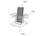
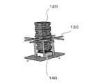
- the rack 130 may support the plurality of containers 120 described above by applying a force to the side surface of some of the containers 120 described above.
- the rack 130 may support the plurality of containers 120 by applying a force to the inner surface or the unevenness of the holes arranged on the side surfaces of the some of the containers 120.
- the rack 130 may support the plurality of containers 120 by applying a force to the bottom surface of the some of the containers 120.
- the rack 130 may support the plurality of containers 120 by applying a force to the side surface and the bottom surface of the part of the containers 120.
- the space 322 is an opening formed by the frame 222 when the frame 222 is virtually moved from the installation position of the frame 222 to the position of the floor 10 along a direction substantially perpendicular to the floor 10.
- it may be a region through which the opening formed in the frame 222 passes.
- the direction substantially perpendicular to the floor 10 may be a vertical direction, or may be a direction inclined from the vertical direction so that the plurality of containers 120 supported by the rack 130 do not fall or collapse due to gravity.
- the upper end of the space 322 may be surrounded by the frame 222.
- the side surface of the space 322 may be surrounded by the space 324.
- the automated warehouse 100 can stack and store a plurality of containers 120 in the vertical direction.
- the plurality of containers 120 stacked in a line in the vertical direction are supported by the rack 130 at a predetermined height from the floor 10, for example.
- the space below the container 120 supported by the rack 130 can be used as a transfer path for another container 120.
- the transport vehicle 140 has a rotating mechanism that rotates a mounting surface on which the container 120 is mounted in a substantially horizontal direction, and at least one of the position and the posture of the container 120 is the operation of the rotating mechanism. Adjusted by.
- the rotating mechanism may be incorporated in an elevating device that moves the mounting surface in a substantially vertical direction, or may be arranged at a lower portion of the elevating device, and between the elevating device and the mounting surface. It may be arranged.
- At least one of the position and the attitude of the container 120 is adjusted by the movement of the carrier vehicle 140 and the operation of the above rotation mechanism.
- the relative positions of the container 120 and the rack 130 are adjusted by the translational movement of the transport vehicle 140.
- the angle formed by the reference plane of the container 120 and the reference plane of the rack 130 is adjusted by the operation of the above rotation mechanism.
- the angle formed by the reference plane of the container 120 and the reference plane of the rack 130 may be adjusted by a combination of the rotational movement or turning movement of the transport vehicle 140 and the operation of the above-described rotation mechanism.
- the shape and size of the rack 130 are designed so that the container 120 can freely move in the vertical direction when at least one of the position and the attitude of the container 120 satisfies a specific condition. There is. Therefore, in the transfer process of the container 120, at least one of the position and the posture of the container 120 is adjusted, so that (i) the rack 130 supports the container 120 and the vertical movement of the container 120 is restricted by the rack 130. And (ii) the rack 130 does not support the container 120 and the vertical movement of the container 120 is not limited by the rack 130. Details of the switching of the above states will be described later.
- the container 120 is stored in the rack 130 by adjusting the rotation and lifting of the newly stored container 120. Further, the container 120 that is already stored is taken out of the rack 130 by adjusting the rotation and lifting of the container 120. Details of the storage procedure and the extraction procedure of the container 120 will be described later.
- each of the one or more containers 120 is used to house one or more items.
- the material, shape, and size of the container 120 are determined, for example, in consideration of the storage efficiency of the articles and the ease of handling.
- the shape and size of the container 120 are not particularly limited, but for example, the width is 20 cm to 1 m, the height is 20 cm to 1 m, and the depth is 20 cm to 1 m. Details of the container 120 will be described later.
- each of the one or more racks 130 supports one or more containers 120.
- the rack 130 supports a plurality of containers 120 stacked in a row.
- the rack 130 may include a plurality of containers 120 stacked in a line.
- the container 120 arranged at any position may be supported from below. Thereby, the rack 130 can support all of the plurality of containers 120 stacked in a line.
- each of the plurality of racks 130 supports one or more containers 120 at a position above the floor 10.
- the distance H22 between the floor 10 and the bottom surface of the container 120 arranged at the bottom among the one or more containers 120 supported by the rack 130 is the floor 10 and the carrier vehicle 140.
- the distance is larger than the distance H24 from the upper surface of the container 120 arranged at the top. Accordingly, each of the one or more transport vehicles 140 can travel under the plurality of containers supported by the one or more racks 130, with at least one container 120 mounted.
- the frame 222 of the rack 130 supports the container 120 at a predetermined position by supporting a part of the outside of the container 120 from below.
- the frame 222 may support a part of the outer bottom surface of the container 120 from below, or may support a part of the outer side surface of the container 120 from below.
- the frame 222 may support the container 120 at at least two points.
- the frame 222 may support the container 120 at three points or four points.
- the frame 222 may support the container 120 at five or more positions.
- the distance between the frame 222 and the floor 10 is predetermined when the frame 222 supports the lowest container 120 of the one or more containers 120 supported by the rack 130. It is determined that the transport vehicle 140 having one container 120 mounted therein can travel below the one or more containers 120 supported by the rack 130. In another embodiment, the distance between the frame 222 and the floor 10 is predetermined when a predetermined second number of containers 120 are connected below the containers 120 directly supported by the frame 222. It is determined that the transport vehicle 140 carrying the first number of containers 120 can travel under the one or more containers 120 supported by the rack 130.
- the distance between the frame 222 and the floor 10 may be changed dynamically.
- an actuator (not shown) arranged on the frame support 224 changes the vertical position of the frame 222. This prevents the frame 222 of the rack 130 or the container 120 supported by the rack 130 from colliding with the container mounted on the transport vehicle 140.
- the transport vehicle 140 adjusts at least one of the position and the posture of the container 120 while the position and the posture of the frame 222 are fixed by the frame support 224. The state in which the movement in the direction is limited by the frame 222 and the state in which the movement in the up and down direction of the container 120 is not limited by the frame 222 are switched (ii).
- the frame 222 is disposed inside the space 322 when the angle formed between the reference plane 126 of the container 120 and the reference plane 226 of the frame support 224 satisfies a predetermined condition. Is placed at a position that restricts the vertical movement of the. In this case, for example, the frame 222 hinders the downward movement of the container 120, so that the container 120 is supported by the rack 130.
- the frame 222 is arranged at a position where the vertical movement of the container 120 arranged inside the space 322 is not restricted when the angle formed by the reference surface 126 and the reference surface 226 does not satisfy a predetermined condition. It In this case, since the frame 222 does not hinder the vertical movement of the container 120, the container 120 arranged inside the space 322 can freely move in the vertical direction.
- the angle formed by the reference plane 126 and the reference plane 226 is the angle formed by the two normal vectors when the start point of the normal vector of the reference plane 126 and the start point of the normal vector of the reference plane 226 are overlapped. Among them, the angle may be 0 degree or more and 180 degrees or less.
- the predetermined condition may be a condition that an angle formed by the reference plane 126 and the reference plane 226 is within a predetermined numerical range. In the above numerical range, only the upper limit value may be determined, only the lower limit value may be determined, or the upper limit value and the lower limit value may be determined.
- the above numerical range is, for example, the external shape and size of the container 120, the external shape and size of the rack 130, a target value relating to at least one of the loading time and the unloading time of the container 120, the target value of seismic performance, and the container 120. Is determined based on at least one of the target value of the positioning accuracy when storing the data in the rack 130 and the target value of the degree of effective use of the container 120.
- Seismic performance may be defined as the magnitude of an earthquake in which the rack 130 can support a predetermined number of vertically stacked containers 120 without collapsing. The magnitude of the earthquake is exemplified by the seismic intensity or maximum acceleration of the earthquake.
- the extent to which the container 120 is effectively used may be referred to as the volume of the accommodation space of the container 120 (may be referred to as Vs) and the volume of the dead space formed inside the accommodation space (may be referred to as Vd). .) and.
- the degree of effective use of the container 120 may be defined as Vs/(Vs+Vd) or Vs/Vd, for example.
- the above numerical range may be determined such that the larger the target value for at least one of the loading time and the unloading time, the larger the upper limit of the above numerical range.
- the above numerical range may be determined such that the lower the seismic performance target value, the larger the lower limit of the numerical range.
- the numerical range may be determined such that the larger the target value of the positioning accuracy, the narrower the width of the numerical range.
- the greater the variation in the diameter of the circumscribed circle of the cross-sectional shape of the container 120 in the direction of extension of the side surface of the container 120 may be referred to as the axial direction
- the larger the angle the larger the contact area between the container 120 and the rack 130.
- the rotation speed of the container 120 is constant, the smaller the above angle, the shorter the loading time and the unloading time of the container 120 can be. Further, if the target values of the loading time and the unloading time of the container 120 are constant, the rotation speed of the container 120 can be decreased as the angle is smaller. The lower the rotation speed of the container 120, the more the collapse of the container 120 during loading or unloading of the container 120 is suppressed.
- the axial direction of the container 120 may be a direction substantially perpendicular to the bottom surface of the container 120 or a direction from the bottom surface of the container 120 toward the opening.
- the axial direction of the container 120 may be the depth direction of the accommodation space of the container 120, or may be the vertical direction when the container 120 is stored in the rack 130.
- the reference surface 126 of the container 120 is preferably a surface that is arranged substantially perpendicular to the floor 10 when the container 120 is stored in the rack 130.
- the reference plane 126 of the container 120 may be a plane that forms an angle of about 90 degrees between the normal vector of the reference plane 126 and the vertical direction when the container 120 is stored in the rack 130.
- the reference surface 226 of the rack 130 is preferably a surface that is arranged substantially perpendicular to the floor 10 when the rack 130 is installed on the floor 10.
- the reference plane 226 of the rack 130 may be a plane where the angle formed by the normal vector of the reference plane 226 and the vertical direction is about 90 degrees when the rack 130 is installed on the floor 10.
- the frame 222 has four beam members.
- each of the four beam members is supported by the two frame supports 224.
- Each of the four beam members may be arranged so that the extending direction of the beam member and the extending direction of the two frame supports 224 are substantially perpendicular to each other.
- each of the four beam members has a distance between the lower end of the beam member and the installation surface that is required to pass the transport vehicle 140 carrying a predetermined number of containers 120. It may be placed at a position larger than the height.
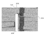
- the height HF of the frame 222 or the beam member forming the frame 222 may be smaller than the height of the cutout portion 124 of the container 120. Thereby, a part of each of the plurality of notches 124 can be fitted into the rack 130. As a result, the container 120 can be prevented from tipping or collapsing due to vertical vibration or horizontal vibration.
- the frame support 224 of the rack 130 is arranged between the frame 222 and the floor 10.
- the frame support 224 transfers the load of the one or more containers 120 received by the frame 222 to the floor 10.
- the frame support 224 positions the frame 222 at the predetermined height described above.
- the rack 130 has four frame supports 224.
- Each of the four frame supports 224 may have a columnar shape.
- Each of the four frame supports 224 may be arranged so that one end thereof contacts the floor 10.
- the arrangement of the four frame supports 224 is such that, on the surface of the floor 10, for example, the length of the diagonal line of the quadrangle circumscribing the four frame supports 224 is the diameter of the first circumscribing circle of the container 120 or the transport vehicle 140. Is determined to be larger than the minimum rotation diameter of. Details of the first circumscribing circle and the minimum rotation diameter will be described later.
- the arrangement of the four frame supports 224 may be determined such that the length of each side of the above-described quadrangle is smaller than the diameter of the first circumscribing circle of the container 120 or the minimum rotation diameter of the transport vehicle 140. ..
- the arrangement of the four frame supports 224 may be determined such that the maximum value of the length of each side of the above-described quadrangle is larger than the width required for the transportation of the transport vehicle 140 carrying the container 120. ..
- the first circumscribing circle of the container 120 is arranged so that the bottom surface of the container 120 is horizontal with the opening of the container 120 facing upward, and the outer periphery of the container 120 is cut along a horizontal plane passing through the upper end of the cutout portion 124 of the container 120. It may be a circle circumscribing the cross-sectional shape (may be referred to as the first cross-sectional shape) obtained in this way.
- the minimum rotation diameter of the carrier vehicle 140 is when the carrier vehicle 140 turns by manipulating the steering wheel to the maximum, or when the carrier vehicle 140 rotates on the spot about an axis substantially vertical to the floor 10. In addition, the diameter of the circle drawn by the outermost portion of the transport vehicle 140 may be used.
- the surface of the floor 10 may be substantially flat.
- the wire 232 of the rack 130 is arranged above the frame 222.
- the rack 130 may have a plurality of wires 232.
- the plurality of wires 232 may be arranged above each column or each row of the plurality of racks 130 arranged in a matrix.
- the plurality of wires 232 may be arranged above a part of a plurality of columns or a part of a plurality of rows of the plurality of racks 130 arranged in a matrix.
- One or a plurality of wires 232 may be arranged so as to surround above the outer periphery of the plurality of racks 130 arranged in a matrix. This can prevent the one or more containers 120 supported by the rack 130 from falling or collapsing.
- a plurality of wires 232 having different heights to be installed may be arranged above the same column or row of the plurality of racks 130 arranged in a matrix. This can further prevent the one or more containers 120 supported by the rack 130 from falling or collapsing.
- the wire support 234 of the rack 130 supports one or more wires 232.
- the wire support 234 arranges the one or more wires 232 at a predetermined height.
- the rack 130 may have multiple wire supports 234. This can prevent the one or more containers 120 supported by the rack 130 from falling or collapsing.
- the transport vehicle 140 transports at least one container 120 between the first position and the second position.
- the first position and the second position may be different positions inside the automated warehouse 100.
- the carrier vehicle 140 transfers the container 120 to and from the rack 130.
- carrier 140 loads containers 120 onto racks 130.
- carrier 140 removes container 120 from rack 130.
- the carrier vehicle 140 can move the container 120 in the vertical direction.
- the transport vehicle 140 maintains the container 120 at a relatively low position (sometimes referred to as a traveling position) when traveling under the rack 130.
- the carrier vehicle 140 moves the container 120 up and down when loading the container 120 into the rack 130 or taking out the container 120 from the rack 130.
- the transport vehicle 140 includes a transport vehicle 242 that transports the container 120 between the rack 130 and the picking device 150, and a container 242 from the picking device 150 to another location inside or outside the automated warehouse 100.
- a transport vehicle 244 for transporting 120 may be included.
- the transport vehicle 242 and the transport vehicle 244 may have the same configuration or different configurations. Details of the carrier vehicle 140 will be described later.
- the floor 10 may be an example of an installation surface.
- the automated warehouse 100 may be an example of a storage system.
- the container 120 may be an example of one or more containers.
- the container 120 may be an example of at least one container.
- the container 120 may be an example of the first container, the second container, or the third container.
- the upper surface of the cutout portion 124 may be a part of the first region.
- the side surface of the cutout portion 124 may be a part of the second region.
- the reference surface 126 may be an example of a reference surface for one or more container side members.
- the rack 130 may be an example of a pedestal.
- the transport vehicle 140 may be an example of a transport robot.
- the management server 160 may be an example of an operation management unit.
- the details of the rack 130 have been described, taking as an example the case where the outer shape of each beam member that constitutes the frame 222 is a quadrangular prism.
- the external shape of the beam member is not limited to the rectangular column.
- the external shape of the beam member may be a column having any cross-sectional shape.
- the cross-sectional shape of the beam member may be formed by a straight line, and at least a part of the cross-sectional shape of the beam member may include a curved line.
- all the interior angles of the polygon may be substantially right angles, or at least a part of the interior angles of the polygon may be acute angles.
- a step is formed on the upper surface of the frame 222.
- a step is formed on the upper surface of the frame 222.
- the cross-sectional shape of the beam member is a polygon and at least a part of the inner angle of the polygon is an acute angle, for example, an inclined surface is formed on the upper surface of the frame 222.
- the rack 130 is not limited to this embodiment.
- each of the two or more frame supports 224 is formed. At least a part of one or a plurality of convex portions arranged on the outer periphery of the container 120 enters the concave portion, and the concave portion of the frame support 224 supports the convex portion of the container 120 from below, so that the rack 130 supports the container 120.
- the rack 130 may have the frame 222 functioning as a beam member, or may not have the frame 222.
- each unit of the automated warehouse 100 may be realized by a personal computer or a mobile terminal.
- the mobile terminal include a mobile phone, a smartphone, a PDA, a tablet, a notebook computer or a laptop computer, a wearable computer, and the like.
- Each unit of the automated warehouse 100 may store information using a distributed ledger technology such as a block chain or a distributed network.
- the information processing apparatus having the above-described general configuration includes (i) a data processing apparatus having a processor such as CPU and GPU, ROM, RAM, communication interface, etc., and (ii) keyboard, pointing device, touch panel, camera, voice input.
- a data processing apparatus having a processor such as CPU and GPU, ROM, RAM, communication interface, etc.
- keyboard pointing device, touch panel, camera, voice input.
- storage device such as memory, HDD, SSD (external (Including a storage device).
- the above program may be installed in a computer forming at least a part of the automated warehouse 100 from a computer-readable medium or a storage device connected to a network.
- the computer may function as at least a part of each unit of the automated warehouse 100.
- the information processing described in the above program is a concrete example in which the software associated with the program and the various hardware resources of the automated warehouse 100 or a part thereof cooperate with each other when the program is read by a computer. Functions as a means.
- the above-mentioned specific means realizes the calculation or processing of information according to the purpose of use of the computer in this embodiment, whereby the automatic warehouse 100 according to the purpose of use is constructed.
- the above information processing method controls an operation of a transfer robot including a mounting unit capable of mounting at least one of the containers, an elevating unit that moves the mounting unit in a vertical direction, and a moving unit that moves the transfer robot. It may be a control method.
- the control method described above has, for example, a procedure in which the moving unit moves the transfer robot to transfer the container into the elevating space of the gantry.
- the moving unit moves the transfer robot and adjusts the position of the container such that the angle formed by the reference plane of the container and the reference plane of the gantry does not satisfy a predetermined condition. Have a procedure to do.
- the above control method has a procedure in which, for example, the elevating unit moves the mounting unit upward so that the lower end of the first region of the container is disposed above the upper ends of the plurality of support units of the gantry.
- the moving unit moves the transfer robot, and the position of the container is adjusted so that the angle formed by the reference plane of the container and the reference plane of the gantry satisfies a predetermined condition. Have a procedure to do.
- the above control method may include a procedure in which the moving unit moves the transfer robot to the inside of the lifting space of the gantry.
- the moving unit moves the transfer robot so that the position of the mounting unit or the container located at the top of at least one container mounted on the mounting unit is moved to a specific position below the container supported by the gantry. Adjustment procedures may be included.
- a step of moving the mounting portion upward by the elevating portion, so that the mounting portion or a container located at the top of at least one container mounted on the mounting portion supports the container supported by the gantry.
- the moving unit may move the transfer robot to adjust the position of the container such that the angle formed by the reference surface of the first container and the reference surface of the gantry does not satisfy a predetermined condition. ..
- the elevating unit may move the mounting unit downward so that the upper end of the first region of the container supported by the gantry is arranged below the lower ends of the plurality of supporting units of the gantry.
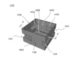
- FIG. 4 schematically shows an example of the container 120.
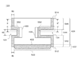
- FIG. 5 schematically shows an example of a sectional shape of the container 120 taken along the line AA′.
- FIG. 6 schematically shows an example of the cross-sectional shape of the container 120 taken along the line BB′.
- FIG. 7 schematically shows an example of a cross-sectional shape in the CC′ cross section of the container 120.
- FIG. 8 schematically shows an example of the positional relationship between the container 120 and the wire 232.
- the container 120 includes a bottom plate 422, side walls 424, and a cover 430. As a result, an accommodation space 440 for accommodating the article is formed inside the container 120. Further, in the present embodiment, a plurality of cutouts 124 are arranged outside the side wall 424. A part of the side wall 424 is used as the reference surface 126 of the container 120.
- the bottom plate 422 closes the opening formed at one end of the side wall 424.
- a part of the bottom plate 422 may form a part of the side surface of the container 120.
- at least a part of the side wall 424 has a hollow columnar shape.
- the side wall 424 is arranged so as to extend to one side of the bottom plate 422.
- the extending direction (sometimes referred to as an axial direction) of the side wall 424 may be substantially parallel to the normal direction of the plane arranged on at least a part of the bottom plate 422.
- the cover 430 constitutes the outer shape of the cutout portion 124.
- the cover 430 is arranged so as to project from the inner surface of the side wall 424 toward the inside of the container 120.
- the cover 430 includes, for example, a member forming the upper surface of the cutout portion 124, a member forming the lower surface of the cutout portion 124, and a member forming the side surface of the cutout portion 124.
- Each of the member forming the upper surface of the cutout portion 124, the member forming the lower surface of the cutout portion 124, and the member forming the side surface of the cutout portion 124 may be a flat member or a curved member. It may be a combination of a flat member and a curved member.
- the shape of the member forming the upper surface of the cutout portion 124 may be configured to match the shape of the upper surface of the frame 222.
- the member forming the upper surface of the cutout portion 124 may be a flat plate.
- the member forming the upper surface of the cutout portion 124 includes a concave portion corresponding to the convex portion of the frame 222 and a convex portion corresponding to the concave portion of the frame 222.
- the lower end 512 of the side wall 424 contacts the bottom plate 422.
- the upper end 514 of the side wall 424 constitutes the opening of the container 120.
- the convex portion 522 is arranged outside the bottom plate 422. The shape and size of the convex portion 522 may be determined based on the shape and size of the opening of the container 120.
- the size of the convex portion 522 is smaller than the size of the opening of the container 120.
- the distance WL from the outer edge of the bottom surface of the container 120 to the protrusion 522 at the lower end of the container 120 is smaller than the distance WU from the outer edge of the side surface of the container 120 at the upper end of the container 120 to the opening. Accordingly, when the two containers 120 are stacked vertically, the convex portion 522 of the upper container 120 is fitted into the opening of the lower container 120. As a result, the collapse or collapse of the container 120 can be suppressed.
- the sidewall 424 has a region 542, a region 544, and a region 546 along the axial direction of the sidewall 424.
- Each of the region 542, the region 544, and the region 546 may be a region that extends in the axial direction of the sidewall 424.
- the area 542 is arranged adjacent to the area 544.
- the region 544 is arranged adjacent to the regions 542 and 546.
- the area 542 is arranged closer to the bottom plate 422 than the area 544.
- the region 546 is arranged at a position farther from the bottom plate 422 than the region 544.
- the notch 124 is formed in the region 544.
- the area 544 is formed with a surface 552 that contacts the rack 130 when the container 120 is supported by the rack 130. Accordingly, the rack 130 can hold the container 120 at a predetermined height by supporting the surface 552 of the container 120 from below.
- the height HD of the area 544 (sometimes referred to as the height of the cutout 124) may be greater than the height HF of the frame 222 shown in FIG. Thereby, a part of each of the plurality of notches 124 can be fitted into the rack 130. As a result, the container 120 can be prevented from tipping or collapsing due to vertical vibration or horizontal vibration.
- FIG. 6 may be an example of a cross-sectional view when the region 546 of the sidewall 424 is cut along a plane substantially perpendicular to the axial direction of the sidewall 424.
- FIG. 6 shows the cross-sectional shape of sidewall 424 in region 546, along with rack 130.
- FIG. 6 shows a state in which the angle formed by the reference plane 126 of the container 120 and the reference plane 226 of the rack 130 is outside the predetermined numerical range, and the rack 130 does not limit the vertical movement of the container 120.
- the relationship between the outer shape of the container 120 and the outer shape of the rack 130 is shown.
- the cross-sectional shape of the side wall 424 in the region 542 has the same shape as the cross-sectional shape of the side wall 424 in the region 546.
- the opening is formed by the inner surface of the frame 222.
- the opening of the frame 222 has a rectangular cross-sectional shape with a long side length of LX and a short side length of LY.
- the cross-sectional shape of the opening of the frame 222 is rectangular as an example.
- the cross-sectional shape of the opening is not limited to this embodiment.
- the cross-sectional shape of the opening may be square, may be polygonal other than square, and may include curvilinear.
- the long side of the quadrangle may be an example of the longest side of the polygon.
- the container 120 is arranged at a position where the entire container 120 fits inside the opening of the frame 222.
- the container 120 is arranged at a position where the center 602 of the circumscribing circle 600 coincides with the center of the opening of the frame 222.
- the center of the opening of the frame 222 may be the center of the circumscribed circle or the inscribed circle of the cross-sectional shape of the opening of the frame 222.
- a gap GX may be formed between the container 120 and the short side of the opening of the frame 222.
- a gap GY may be formed between the container 120 and the long side of the opening of the frame 222.
- the diameter of the circumscribing circle 600 of the sectional shape in the region 546 of the side wall 424 is larger than the length LX of the long side of the opening of the frame 222.
- FIG. 7 may be an example of a cross-sectional view when the region 544 of the sidewall 424 is cut along a plane substantially perpendicular to the axial direction of the sidewall 424.
- FIG. 7 shows the cross-sectional shape of sidewall 424 in region 544, along with rack 130.
- the angle formed by the reference plane 126 of the container 120 and the reference plane 226 of the rack 130 is within a predetermined numerical range, and the rack 130 restricts the vertical movement of the container 120.
- the relationship between the outer shape of the container 120 and the outer shape of the rack 130 is shown.
- FIG. 7 shows a state in which the container 120 in FIG. 6 is rotated about 15 degrees counterclockwise.
- the center 602 of the circumscribing circle 600 and the center 702 of the circumscribing circle 700 may be arranged at different positions on the extension axis of the side wall 424.
- the diameter of the circumscribing circle 700 may be larger than the length LX of the long side of the opening of the frame 222, may be equal to the length LX of the long side, or may be smaller than the length LX of the long side.
- the diameter of the circumscribing circle 700 may be larger than the length LY of the short side of the opening of the frame 222, may be equal to the length LY of the long side, or may be smaller than the length LY of the long side.
- the bottom plate 422 may be an example of a bottom member.
- the side wall 424 may be an example of a side member.
- the area 542 may be an example of the first area.
- the cross-sectional shape of the region 542 of the sidewall 424 may be an example of the first cross-sectional shape.
- the area 544 may be an example of the second area.
- the cross-sectional shape of the region 544 of the sidewall 424 may be an example of the second cross-sectional shape.
- the area 546 may be an example of the first area.
- the cross-sectional shape of the region 546 of the sidewall 424 may be an example of the first cross-sectional shape.
- the circumscribing circle 600 may be an example of the first circumscribing circle.
- the circumscribing circle 700 may be an example of the second circumscribing circle.
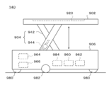
- control unit 960 controls each unit of the carrier vehicle 140 to store the specific container 120 in the specific rack 130.
- the control unit 960 may control each unit of the transport vehicle 140 to take out the specific container 120 from the specific rack 130. Details of the control unit 960 will be described later.
- the sense unit 962 includes various sensors.
- the sense unit 962 may include a position sensor for acquiring information indicating the position of the transport vehicle 140.
- the sense unit 962 may include a load sensor that detects a load applied to the lifting table 902.
- the sense unit 962 may include a lift amount sensor that detects the amount of movement of the lift table 902.
- the position sensor As the position sensor, (i) a distance measuring sensor that measures the distance from the wall 20 of the automated warehouse 100, and (ii) information given to a specific position on the floor 10 and acquiring information indicating the position.
- a sensor etc. are illustrated.
- the sensor may be a camera, a magnetic sensor, or a beacon receiver.
- the wheels 980 and the drive wheels 982 support the carrier vehicle 140.
- the motor 984 drives the drive wheels 982 to move the transport vehicle 140.
- the motor 984 may drive each of the left and right drive wheels 982 independently. Thereby, the carrier vehicle 140 can rotate or turn on the spot.
- the container 120 may be mounted on the carrier vehicle 140 such that the center 602 of the circumscribing circle 600 and the center 702 of the circumscribing circle 700 substantially match the center 1102 of the circle 1100.
- the installation positions of the wheels 980 and the drive wheels 982 in the vehicle body 906 may be determined so that the wheels 980 and the drive wheels 982 fit within the circle 1100.
- a single storage space is formed by two plate-shaped or trapezoidal frame supports 224 arranged at opposite positions.
- one plate-shaped frame support 224 and two pillar-shaped frame supports 224 arranged at positions opposed to the plate-shaped frame supports 224 provide a single storage. Space is formed.
- the details of the positional relationship between the transport vehicle 140 and the rack 130 have been described, taking as an example the case where a part of the frame 222 and the frame support 224 are shared between the adjacent storage spaces.
- the structure of the rack 130 is not limited to this embodiment.
- a separate rack 130 is provided for each storage space.
- the transport vehicle 140 rotates the container 120 inside the space 322 formed by the rack 130, the transport vehicle 140 can be used. Is suppressed from colliding with the frame support 224.
- the transport vehicle 140 and the rack 130 can be designed by the same procedure as the embodiment described with reference to FIG. 11. ..
- the transport vehicle 140 has a rotation mechanism (not shown) for the container 120, and the transport vehicle 140 controls the operation of the rotation mechanism to adjust the attitude of the container 120.
- the transport vehicle 140 can be used. Is suppressed from colliding with the frame support 224.
- the transport vehicle 140 and the rack 130 can be designed by the same procedure as the embodiment described with reference to FIG. 11. ..
- the storage procedure of the container 120 will be described by taking the case where a single container 120 is stored as an example.
- the storage procedure of the container 120 is not limited to this embodiment. In other embodiments, multiple containers 120 may be stored at one time.
- the traveling control unit 1030 controls the motor 984 to move the transport vehicle 140 carrying the container 120 to a position below the target rack 130. Let As a result, the container 120 is transported into the space 322 of the target rack 130.
- the traveling control unit 1030 controls the motor 984 to finely adjust the position of the carrier vehicle 140. Specifically, the traveling control unit 1030 adjusts the position of the container 120 in the x direction and the y direction and the direction of the reference plane 126 of the container 120 in the normal direction. The traveling control unit 1030 sets the position of the container 120 in the x direction and the y direction and the direction of the normal direction of the reference plane 126 of the container 120 so that the rack 130 does not limit the vertical movement of the container 120. May be adjusted.
- the traveling control unit 1030 may be configured such that the center 602 of the circumscribed circle 600 of the container 120 and the center of the circumscribed circle or the inscribed circle of the opening formed by the frame 222 of the rack 130 coincide with each other in the x direction of the container 120. And the position in the y direction is adjusted. Further, the traveling control unit 1030 sets the reference plane 126 of the container 120 and the reference plane 226 of the target rack 130 in the normal direction of the reference plane 126 of the container 120 so as not to satisfy a predetermined condition. Adjust the orientation.
- the lifting device control unit 1040 controls the actuator 944 to raise the lifting table 902.
- the lifting device control unit 1040 lifts the lifting table 902 until the upper surface of the cutout portion 124 of the newly stored container 120 (that is, the lower end of the region 546) is located above the upper surface of the frame 222. You may let me.
- the lifting device control unit 1040 controls the actuator 944. Then, the lifting of the lifting table 902 is stopped. At this time, the lower surface of the cutout portion 124 of the container 120 (that is, the lower end of the region 544) is located below the lower surface of the frame 222.
- the traveling control unit 1030 controls the motor 984 to rotate or turn the transport vehicle 140 on the spot. This causes the container 120 to rotate about an axis substantially perpendicular to the floor 10.
- the traveling control unit 1030 may control the motor 984 so that the container 120 rotates about the center 602 of the circumscribing circle 600 or the center 702 of the 7000.
- the lifting device control unit 1040 controls the actuator 944 to lower the lifting table 902.
- the upper surface of the cutout portion 124 of the container 120 and the upper surface of the frame 222 come into contact with each other, and the frame 222 supports the container 120 from below.
- the container 120 to be stored is stored in the rack 130.
- the lifting device control unit 1040 controls the actuator 944 to lower the lifting table 902 to the traveling position. Further, the traveling control unit 1030 controls the motor 984 to rotate or turn the transport vehicle 140 on the spot. As a result, the transport vehicle 140 can move from the inside of the space 322 of the rack 130 to the outside of the rack 130 by passing between the two frame supports 224.
- the storage procedure of the container 120 will be described by taking the case where a single container 120 is stored as an example.
- the storage procedure of the container 120 is not limited to this embodiment. In other embodiments, multiple containers 120 may be stored at one time.
- the traveling control unit 1030 controls the motor 984 to move the transport vehicle 140 loaded with the container 120 to a position below the target rack 130. Let As a result, the container 120 is transported into the space 322 of the target rack 130.
- the one or more containers 120 that are already supported by the rack 130 have reference planes such that the angle between the reference plane 126 of these containers 120 and the reference plane 226 of the frame support 224 satisfies a predetermined condition. It is stored in the rack 130 with the orientation of 126 adjusted. Therefore, the traveling control unit 1030 controls the motor 984 to control the center 602 of the circumscribed circle 600 of the container A and the circumscribed circle 600 of the newly stored container 120 (sometimes referred to as the container B). The position of the container 120 in the x direction and the y direction is adjusted so that the center 602 coincides.
- the lifting device control unit 1040 controls the actuator 944 to raise the lifting table 902.
- the elevating device controller 1040 may elevate the elevating table 902 until the upper end of the container B reaches a position supporting the lower end of the container A.
- the container B is arranged at the bottom of the one or more containers 120 already supported by the rack 130.
- the upper surface of the cutout portion 124 of the container A may or may not be in contact with the upper surface of the frame 222.
- the upper surface of the cutout portion 124 of the container A does not contact the upper surface of the frame 222, and the lower surface of the cutout portion 124 of the container A contacts the lower surface of the frame 222.
- the lifting device control unit 1040 determines that the uppermost container 120 among the plurality of containers 120 mounted on the transport vehicle 140 has the upper end.
- the elevating table 902 may be raised until it reaches a position supporting the lower end of A.
- the traveling control unit 1030 controls the motor 984 to rotate or turn the carrier vehicle 140 on the spot.
- the plurality of containers 120 stacked in one row rotate about an axis substantially vertical to the floor 10.
- the traveling control unit 1030 may control the motor 984 so that the container 120 rotates about the center 602 of the circumscribing circle 600 or the center 702 of the 7000.
- traveling control unit 1030 may control the motor 984 so that the rotation or turning direction of the transport vehicle 140 is opposite to the rotation or turning direction in FIG.
- the traveling control unit 1030 may control the motor 984 so that the absolute value of the rotation or turning angle of the carrier vehicle 140 substantially matches the absolute value of the rotation or turning angle in FIG.
- the lifting device control unit 1040 controls the actuator 944 to lower the lifting table 902.
- the upper surface of the cutout portion 124 of the container 120 that is newly supported by the rack 130 and the upper surface of the frame 222 come into contact with each other, and the frame 222 supports the container 120 from below.
- the container 120 to be stored is stored in the rack 130.
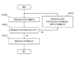
- step 2422 step may be abbreviated as S.
- the communication unit 964 receives an instruction from the management server 160.
- the above instruction includes, for example, (i) information indicating the work type, (ii) identification information of the target rack 130, (iii) position information of the target rack 130, and (iv) the target container 120.
- Identification information (v) position information of the intended container 120, (vi) information indicating the availability of another rack 130 located near the intended rack 130, (vii) destination of the taken-out container 120 At least one of the information indicating
- the lifting/lowering device control unit 1040 determines whether or not the 120 located at the bottom among the one or more 120 supported by the target rack 130 is the target container 120.
- the traveling control unit 1030 and the lifting device control unit 1040 cooperate with each other to set the target rack 130.
- the one or more containers 120 below the target container 120 are taken out.
- the lifting device control unit 1040 may take out a plurality of containers 120 at a time, or may take out one container 120 at a time.
- the position of the lifting table 902 is adjusted to a specific position below the target rack 130 or the target container 120. Specifically, the position and direction of the recess 920 are adjusted so as to match the container P.
- the traveling control unit 1030 controls the motor 984 to rotate or turn the carrier vehicle 140 on the spot.
- the container P, the container Q, the container R, and the container S rotate about an axis substantially vertical to the floor 10.
- the traveling control unit 1030 may control the motor 984 so that the container 120 rotates about the center 602 of the circumscribing circle 600 or the center 702 of the 7000.
- the lifting device control unit 1040 controls the actuator 944 to lower the lifting table 902.
- the lifting/lowering device controller 1040 may lower the lifting/lowering table 902 until the upper end of the region 546 of the container T is located below the lower surface of the frame 222.
- the lifting device control unit 1040 lowers the lifting table 902 to the traveling position.
- the traveling control unit 1030 controls the motor 984 to rotate or turn the transport vehicle 140 on the spot.
- the transport vehicle 140 can move from the inside of the space 322 of the rack 130 to the outside of the rack 130 by passing between the two frame supports 224.
Landscapes
- Engineering & Computer Science (AREA)
- Mechanical Engineering (AREA)
- Aviation & Aerospace Engineering (AREA)
- Radar, Positioning & Navigation (AREA)
- Remote Sensing (AREA)
- Physics & Mathematics (AREA)
- General Physics & Mathematics (AREA)
- Automation & Control Theory (AREA)
- Transportation (AREA)
- Structural Engineering (AREA)
- Civil Engineering (AREA)
- Life Sciences & Earth Sciences (AREA)
- Geology (AREA)
- Warehouses Or Storage Devices (AREA)
- Stacking Of Articles And Auxiliary Devices (AREA)
- Control Of Position, Course, Altitude, Or Attitude Of Moving Bodies (AREA)
Abstract
Description
本出願は、2019年2月25日に出願された米国仮特許出願第62/810,363号、2019年4月26日に出願された国際出願第PCT/JP2019/018116号、及び、2019年4月26日に出願された国際出願第PCT/JP2019/018127号の優先権を主張する。なお、上記の国際出願第PCT/JP2019/018116号、及び、国際出願第PCT/JP2019/018127号は、上記の米国仮特許出願第62/810,363号の優先権を主張する。文献の参照による組み込みが認められる指定国については、参照により、これらの全体が本明細書に組み込まれる。
本出願は、下記の国際出願に関連する。本出願は、米国においては、下記の国際出願の一部継続出願とする。
1.国際出願第PCT/JP2019/018116号 出願日 2019年4月26日
2.国際出願第PCT/JP2019/018127号 出願日 2019年4月26日
[先行技術文献]
[特許文献]
[特許文献1] 特開2012-116651号公報
[特許文献2] 特開2017-132641号公報
[非特許文献]
[非特許文献1] 株式会社岡村製作所、「自動倉庫型ピッキングシステム「AutoStore(オートストア)」日本発売開始」、[Online]、[平成30年10月5日検索]、インターネット<http://www.okamura.co.jp/company/topics/butsuryu/2014/autostore_1.php>
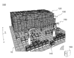
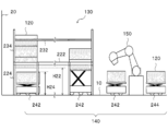
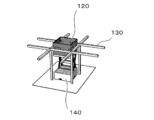
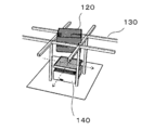
図1、図2及び図3を用いて、自動倉庫100のシステム構成の概要が説明される。図1は、自動倉庫100の内部の一例を概略的に示す。図2は、自動倉庫100のシステム構成の一例を概略的に示す。図3は、自動倉庫100におけるコンテナの保管方法の一例を概略的に示す。
複数のラック130のそれぞれは、例えば、各ラックが所定の位置に設置された場合に、上下方向に積み上げられた複数のコンテナ120の一部を側方又は下方から支持することができるように構成される。例えば、図3に示されるとおり、コンテナ120の外側の側面には、複数の切欠部124が形成される。本実施形態によれば、複数の切欠部124のそれぞれの一部がラック130の一部に嵌め込まれるように配置されることで、ラック130が、コンテナ120を下方から支持する。これにより、ラック130の予め定められた支持位置において、コンテナ120の下方向の移動が抑制され、コンテナ120がラック130に保管され得る。
本実施形態において、自動倉庫100は、複数のコンテナ120を、上下方向に積み上げて保管することができる。上下方向に一列に積み上げられた複数のコンテナ120は、例えば、ラック130により、床10から予め定められた高さに支持される。これにより、ラック130に支持されたコンテナ120の下方の空間が、他のコンテナ120の搬送経路として利用され得る。
[コンテナ120]
本実施形態において、1以上のコンテナ120のそれぞれは、1以上の物品を収容するために用いられる。コンテナ120の材質、形状及び大きさは、例えば、物品の保管効率及びハンドリングの容易性を考慮して決定される。コンテナ120の形状及び大きさは、特に制限されるものではないが、例えば、幅が20cm~1mであり、高さが20cm~1mであり、奥行が20cm~1mである。コンテナ120の詳細は後述される。
本実施形態において、1以上のラック130のそれぞれは、1以上のコンテナ120を支持する。例えば、ラック130は、一列に積み上げられた複数のコンテナ120を支持する。
本実施形態において、ラック130のフレーム222は、コンテナ120の外側の一部を下方から支持することで、コンテナ120を所定の位置に支持する。フレーム222は、コンテナ120の外側の底面の一部を下方から支持してもよく、コンテナ120の外側の側面の一部を下方から支持してもよい。フレーム222は、コンテナ120を少なくとも2点で支持してよい。フレーム222は、コンテナ120を3点で支持してもよく、4点で支持してもよい。フレーム222は、コンテナ120を5点以上の位置で支持してもよい。
本実施形態において、ラック130のフレームサポート224は、フレーム222と、床10との間に配される。フレームサポート224は、フレーム222が受けた1以上のコンテナ120の荷重を、床10に伝達する。フレームサポート224は、フレーム222を、上述された所定の高さに配置する。
本実施形態において、ラック130のワイヤ232は、フレーム222よりも上方に配される。ラック130は、複数のワイヤ232を有してもよい。複数のワイヤ232が、マトリックス状に配された複数のラック130の各列又は各行の上方に配されてもよい。複数のワイヤ232が、複数のワイヤ232が、マトリックス状に配された複数のラック130の複数の列の一部又は複数の行の一部の上方に配されてもよい。1又は複数のワイヤ232が、マトリックス状に配された複数のラック130の外周の上方を囲うように配されてよい。これにより、ラック130に支持された1以上のコンテナ120の転倒又は倒壊が抑制され得る。
本実施形態において、ラック130のワイヤーサポート234は、1又は複数のワイヤ232を支持する。ワイヤーサポート234は、1又は複数のワイヤ232を所定の高さに配置する。ラック130は、複数のワイヤーサポート234を有してもよい。これにより、ラック130に支持された1以上のコンテナ120の転倒又は倒壊が抑制され得る。
本実施形態において、搬送車140は、第1の位置と、第2の位置との間で、少なくとも1つのコンテナ120を搬送する。第1の位置及び第2の位置は、自動倉庫100の内部の異なる位置であってよい。本実施形態において、搬送車140は、ラック130との間でコンテナ120を移載する。一実施形態において、搬送車140は、ラック130にコンテナ120を積み込む。他の実施形態において、搬送車140は、ラック130からコンテナ120を取り出す。
本実施形態において、ピッキング装置150は、一のコンテナ120と、他のコンテナ120との間で、物品を移載する。一実施形態において、ピッキング装置150は、搬送車242に搭載されたコンテナ120に収容されている物品を取り出し、当該物品を、搬送車244に搭載されたコンテナ120に収容する。他の実施形態において、ピッキング装置150は、搬送車244に搭載されたコンテナ120に収容されている物品を取り出し、当該物品を、搬送車242に搭載されたコンテナ120に収容する。
本実施形態において、管理サーバ160は、物品の保管状況を管理する。管理サーバ160は、自動倉庫100の各部を管理してもよい。例えば、管理サーバ160は、自動倉庫100の各部の状態を管理する。管理サーバ160は、管理サーバ160は、1以上の搬送車140のそれぞれの運転を管理してもよい。管理サーバ160は、1以上のラック130のそれぞれの運転を管理してもよい。
自動倉庫100の各部は、ハードウエアにより実現されてもよく、ソフトウエアにより実現されてもよく、ハードウエア及びソフトウエアにより実現されてもよい。自動倉庫100の各部は、その少なくとも一部が、単一のサーバによって実現されてもよく、複数のサーバによって実現されてもよい。自動倉庫100の各部は、その少なくとも一部が、仮想サーバ上又はクラウドシステム上で実現されてもよい。
図12、図13、図14、図15及び図16を用いて、自動倉庫100におけるコンテナ120の格納手順の詳細が説明される。図12~図16は、格納処理の対象となるコンテナ120が格納される直前の時点において、ラック130がコンテナ120を支持していない場合における、コンテナ120の格納手順の一例を示す。
図17、図18、図19、図20、図21、図22及び図23を用いて、自動倉庫100におけるコンテナ120の格納手順の他の例が説明される。図17~図23は、格納処理の対象となるコンテナ120が格納される直前の時点において、ラック130が既に1以上のコンテナ120を支持している場合における、コンテナ120の格納手順の一例を示す。
図24は、コンテナ120の取出手順の一例を概略的に示す。図24は、一列に積み上げられた複数のコンテナ120の中から、目的とするコンテナ120を取り出す手順の一例を示す。
本実施形態においては、説明を簡単にすることを目的として、コンテナ120を搭載していない搬送車140が、一度に1つのコンテナ120を取り出す場合を例として、S2432におけるコンテナ120の取出手順の一例が説明される。しかしながら、コンテナ120の取出手順は本実施形態に限定されない。他の実施形態において、搬送車140は、一度に複数のコンテナ120が取り出されてよい。さらに他の実施形態において、少なくとも1つの他のコンテナ120を搭載した搬送車140が、目的とするコンテナ120を取り出してもよい。
本実施形態においては、説明を簡単にすることを目的として、ラック130が単一のコンテナ120を支持している場合に、コンテナ120を搭載していない搬送車140が、ラック130に支持されているコンテナ120(コンテナTと称される場合がある。)を取り出す場合を例として、S2434におけるコンテナ120の取出手順の一例が説明される。しかしながら、コンテナ120の取出手順は本実施形態に限定されない。他の実施形態において、少なくとも1つの他のコンテナ120を搭載した搬送車140が、目的とするコンテナ120を取り出してよい。
Claims (17)
- 物品を収容するためのコンテナを支持する架台と、
前記コンテナを搬送する搬送ロボットと、
を備え、
前記搬送ロボットは、
前記コンテナを搭載可能な搭載部と、
前記搭載部を上下方向に移動させる昇降部と、
前記架台が前記コンテナの上下方向の移動を制限する状態と、前記架台が前記コンテナの上下方向の移動を制限しない状態とを切り替える切替部と、
を有し、
前記昇降部は、前記架台が前記コンテナの上下方向の移動を制限しない状態において、保管対象となる前記コンテナを、前記架台における前記コンテナの支持位置よりも下方の位置から、前記支持位置まで移動させ、
前記切替部は、前記保管対象となる前記コンテナが前記支持位置に到達した後、前記架台が前記コンテナの上下方向の移動を制限しない状態から、前記架台が前記コンテナの上下方向の移動を制限する状態に切り替える、
保管システム。 - 1以上の架台を備え、物品をコンテナに収容して保管する保管システムであって、
前記コンテナは、
少なくとも一部が中空柱状を有する側面部材と、
前記側面部材の一方の端部に形成された開口を塞ぐ底面部材と、
を備え、
前記コンテナは、
前記側面部材の軸方向に延伸する第1領域と、
前記第1領域に隣接して、前記側面部材の軸方向に延伸する第2領域と、
を備え、
前記第1領域において、前記コンテナの外周を前記側面部材の前記軸方向に略垂直な平面で切断して得られる第1断面形状に外接する第1外接円の直径は、前記第2領域において、前記コンテナの外周を前記側面部材の前記軸方向に略垂直な平面で切断して得られる第2断面形状に外接する第2外接円の直径よりも大きく、
前記第1外接円の中心と、前記第2外接円の中心とは、前記側面部材の延伸軸上の異なる位置に配され、
前記1以上の架台のそれぞれは、
1以上の前記コンテナに含まれる第1コンテナの前記第1領域を下方から支持することで、前記1以上のコンテナを、当該架台が設置される設置面の上方の位置で支持する複数の支持部と、
前記複数の支持部及び前記設置面との間に配され、前記複数の支持部が受けた前記1以上のコンテナの荷重を前記設置面に伝達する複数の基礎部と、
を有し、
前記複数の基礎部の内側には、前記1以上のコンテナが上下方向に移動することのできる昇降空間が形成され、
前記複数の支持部のそれぞれは、(i)前記1以上のコンテナの前記側面部材の基準面と、前記架台の基準面とのなす角度が予め定められた条件を満足する場合には、前記昇降空間における前記1以上のコンテナの上下方向の移動を制限し、且つ、前記角度が前記予め定められた条件を満足しない場合には、前記昇降空間における前記1以上のコンテナの上下方向の移動を制限しない位置であって、(ii)前記架台により支持される前記1以上のコンテナの最下部に位置するコンテナが、前記架台の外部及び前記昇降空間の間における、少なくとも1つの前記コンテナの移動を制限しないような位置に配される、
保管システム。 - 前記保管システムは、1以上の搬送ロボットをさらに備え、
前記1以上の搬送ロボットのそれぞれは、
前記少なくとも1つのコンテナを搭載可能な搭載部を有し、
前記搭載部に搭載された前記少なくとも1つのコンテナを搬送し、
前記複数の支持部のそれぞれは、前記架台が前記1以上のコンテナを支持している場合であっても、前記少なくとも1つのコンテナを搭載した前記1以上の搬送ロボットの少なくとも1つが、前記1以上のコンテナの最下部に位置するコンテナの下方を走行することのできる位置に配される、
請求項2に記載の保管システム。 - 前記1以上の搬送ロボットのそれぞれは、
前記1以上の架台のうち、目的とする架台の前記昇降空間の内部に、前記少なくとも1つのコンテナを搬送し、
前記少なくとも1つのコンテナの基準面と、前記目的とする架台の基準面とのなす角度が、前記予め定められた条件を満足しないように、前記少なくとも1つのコンテナの位置を調整し、
前記少なくとも1つのコンテナに含まれる第2コンテナの前記第1領域の下端が、前記目的とする架台の前記複数の支持部の上端よりも上方に位置するようになるまで、前記搭載部を上方に移動させ、
前記少なくとも1つのコンテナの基準面と、前記目的とする架台の基準面とのなす角度が、前記予め定められた条件を満足するように、前記少なくとも1つのコンテナの位置を調整することで、
前記目的とする架台が支持するコンテナの個数を増加させる、
請求項3に記載の保管システム。 - 前記1以上の搬送ロボットのそれぞれは、
前記1以上の架台のうち、目的とする架台の前記昇降空間の内部に、前記少なくとも1つのコンテナを搬送し、
(i)前記目的とする架台に支持されている前記1以上のコンテナの最下部に位置するコンテナの前記側面部材の延伸軸と、前記少なくとも1つのコンテナの前記側面部材の延伸軸とが一致し、且つ、(ii)前記少なくとも1つのコンテナの基準面と、前記目的とする架台の基準面とのなす角度が、前記予め定められた条件を満足するように、前記少なくとも1つのコンテナの位置を調整し、
前記少なくとも1つのコンテナの最上部に位置するコンテナの上端が、前記目的とする架台に支持されている前記1以上のコンテナの最下部に位置する前記コンテナの下端を支持する位置に達するまで、前記搭載部を上方に移動させ、
前記少なくとも1つのコンテナの基準面と、前記目的とする架台の基準面とのなす角度が、前記予め定められた条件を満足しないように、前記少なくとも1つのコンテナの位置を調整し、
前記少なくとも1つのコンテナに含まれる第2コンテナの前記第1領域の下端が、前記目的とする架台の前記複数の支持部の上端よりも上方に位置するようになるまで、前記搭載部を上方に移動させ、
前記少なくとも1つのコンテナの基準面と、前記目的とする架台の基準面とのなす角度が、前記予め定められた条件を満足するように、前記少なくとも1つのコンテナの位置を調整することで、
前記目的とする架台が支持するコンテナの個数を増加させる、
請求項3に記載の保管システム。 - 前記1以上の搬送ロボットのそれぞれは、
前記1以上の架台のうち、目的とする架台の前記昇降空間の内部に移動し、
前記搭載部、又は、前記搭載部に搭載された前記少なくとも1つのコンテナの最上部に位置するコンテナの位置を、前記目的とする架台に支持されている前記第1コンテナの下方の特定の位置に調整し、
前記搭載部、又は、前記搭載部に搭載された前記少なくとも1つのコンテナの最上部に位置するコンテナが、前記目的とする架台に支持されている前記1以上のコンテナの最下部に位置するコンテナを支持するまで、前記搭載部を上昇させ、
前記第1コンテナの基準面と、前記目的とする架台の基準面とのなす角度が、前記予め定められた条件を満足しないように、前記1以上のコンテナの位置を調整し、
前記目的とする架台に支持されている前記1以上のコンテナのうち、前記第1コンテナよりも上方に位置する第3コンテナの前記第1領域の下端と、前記目的とする架台の前記複数の支持部の上端との上下方向の距離が、0又は予め定められた正の数値範囲内となるまで、前記搭載部を下方に移動させ、
前記第3コンテナの基準面と、前記目的とする架台の基準面とのなす角度が、前記予め定められた条件を満足するように、前記1以上のコンテナの位置を調整することで、
前記目的とする架台が支持するコンテナの個数を減少させる、
請求項3から請求項5までの何れか一項に記載の保管システム。 - 前記予め定められた正の数値範囲は、前記第3コンテナの前記第1領域の下端と、前記目的とする架台の前記複数の支持部の上端との上下方向の距離が、当該予め定められた正の数値範囲内となる場合に、前記目的とする架台に支持されている前記1以上のコンテナのうち、前記第3コンテナの1つ下方に位置するコンテナの前記第1領域の上端が、前記目的とする架台の前記複数の支持部の下端よりも下方に位置するように設定される、
請求項6に記載の保管システム。 - 前記1以上の搬送ロボットのそれぞれは、
前記1以上の架台のうち、目的とする架台の前記昇降空間の内部に移動し、
前記搭載部、又は、前記搭載部に搭載された前記少なくとも1つのコンテナの最上部に位置するコンテナの位置を、前記目的とする架台に支持されている前記第1コンテナの下方の特定の位置に調整し、
前記搭載部、又は、前記搭載部に搭載された前記少なくとも1つのコンテナの最上部に位置するコンテナが、前記目的とする架台に支持されている前記1以上のコンテナの最下部に位置するコンテナを支持するまで、前記搭載部を上昇させ、
前記第1コンテナの基準面と、前記目的とする架台の基準面とのなす角度が、前記予め定められた条件を満足しないように、前記1以上のコンテナの位置を調整し、
前記目的とする架台に支持されている前記第1コンテナの前記第1領域の上端が、前記目的とする架台の前記複数の支持部の下端よりも下方に位置するようになるまで、前記搭載部を下方に移動させることで、
前記目的とする架台が支持するコンテナの個数を減少させる、
請求項3から請求項5までの何れか一項に記載の保管システム。 - 前記搬送ロボットの運転を管理する運転管理部をさらに備える、
請求項3から請求項8までの何れか一項に記載の保管システム。 - 前記1以上の架台のそれぞれは、1以上の前記コンテナに含まれる複数の前記第1コンテナを下方から支持することで、前記1以上のコンテナを、当該架台が設置される前記設置面の上方の位置で支持する、
請求項2から請求項9までの何れか一項に記載の保管システム。 - 物品を収容するコンテナを支持する架台であって、
前記コンテナは、
少なくとも一部が中空柱状の形状を有する側面部材と、
前記側面部材の一方の端部に形成された開口を塞ぐ底面部材と、
を備え、
前記コンテナは、
前記側面部材の軸方向に延伸する第1領域と、
前記第1領域に隣接して、前記側面部材の軸方向に延伸する第2領域と、
を備え、
前記第1領域において、前記コンテナの外周を前記側面部材の前記軸方向に略垂直な平面で切断して得られる第1断面形状に外接する第1外接円の直径は、前記第2領域において、前記コンテナの外周を前記側面部材の前記軸方向に略垂直な平面で切断して得られる第2断面形状に外接する第2外接円の直径よりも大きく、
前記第1外接円の中心と、前記第2外接円の中心とは、前記側面部材の延伸軸上の異なる位置に配され、
前記架台は、
1以上の前記コンテナに含まれる第1コンテナの前記第1領域を下方から支持することで、前記1以上のコンテナを、当該架台が設置される設置面の上方の位置で支持する複数の支持部と、
前記複数の支持部及び前記設置面との間に配され、前記複数の支持部が受けた前記1以上のコンテナの荷重を前記設置面に伝達する複数の基礎部と、
を有し、
前記複数の基礎部の内側には、前記1以上のコンテナが上下方向に移動することのできる昇降空間が形成され、
前記複数の支持部のそれぞれは、(i)前記1以上のコンテナの前記側面部材の基準面と、前記架台の基準面とのなす角度が予め定められた条件を満足する場合には、前記昇降空間における前記1以上のコンテナの上下方向の移動を制限し、且つ、前記角度が前記予め定められた条件を満足しない場合には、前記昇降空間における前記1以上のコンテナの上下方向の移動を制限しない位置であって、(ii)前記架台により支持される前記1以上のコンテナの最下部に位置するコンテナが、前記架台の外部及び前記昇降空間の間における、少なくとも1つの前記コンテナの移動を制限しないような位置に配される、
架台。 - 前記複数の基礎部は、4本の支柱部材を有し、
前記複数の支持部は、4本の梁部材を有し、
前記4本の支柱部材のそれぞれは、一方の端部が前記設置面に接触するように配され、
前記設置面において、(i)前記4本の支柱部材に外接する四角形の対角線の長さは、前記第1外接円の直径、又は、前記コンテナを搬送するための搬送ロボットの最小回転直径よりも大きく、(ii)当該四角形の各辺の長さは、前記第1外接円の直径又は前記最小回転直径よりも小さく、(iii)当該四角形の各辺の長さの最大値は、前記コンテナを搭載した前記搬送ロボットの通行に必要とされる幅よりも大きく、
前記4本の梁部材のそれぞれは、
2本の前記支柱部材に支持され、
当該梁部材の下端及び前記設置面の距離が、前記コンテナを搭載した前記搬送ロボットの通行に必要とされる高さよりも大きくなる位置に、当該梁部材の延伸方向と、当該2本の支柱部材の延伸方向とが略垂直になるように配され、
前記最小回転直径は、前記搬送ロボットが、舵取り車輪を最大に操作して旋回した場合、又は、前記搬送ロボットが、前記設置面に略垂直な軸を中心として、その場で回転した場合に、前記搬送ロボットの最外側に位置する部位が描く円の直径である、
請求項11に記載の架台。 - 前記架台は、前記架台に支持された前記1以上のコンテナの転倒を防止するための転倒防止部材をさらに備える、
請求項11又は請求項12に記載の架台。 - 物品を収容するコンテナを搬送して、前記コンテナを架台に保管するために使用される搬送ロボットの動作を制御するための制御装置であって、
前記コンテナは、
少なくとも一部が中空柱状の形状を有する側面部材と、
前記側面部材の一方の端部に形成された開口を塞ぐ底面部材と、
を備え、
前記コンテナは、
前記側面部材の軸方向に延伸する第1領域と、
前記第1領域に隣接して、前記側面部材の軸方向に延伸する第2領域と、
を備え、
前記第1領域において、前記コンテナの外周を前記側面部材の前記軸方向に略垂直な平面で切断して得られる第1断面形状に外接する第1外接円の直径は、前記第2領域において、前記コンテナの外周を前記側面部材の前記軸方向に略垂直な平面で切断して得られる第2断面形状に外接する第2外接円の直径よりも大きく、
前記第1外接円の中心と、前記第2外接円の中心とは、前記側面部材の延伸軸上の異なる位置に配され、
前記架台は、
前記コンテナの前記第1領域を下方から支持することで、前記コンテナを、当該架台が設置される設置面の上方の位置で支持する複数の支持部と、
前記複数の支持部及び前記設置面との間に配され、前記複数の支持部が受けた前記コンテナの荷重を前記設置面に伝達する複数の基礎部と、
を備え、
前記複数の基礎部の内側には、前記コンテナが上下方向に移動することのできる昇降空間が形成され、
前記複数の支持部のそれぞれは、(i)前記コンテナの前記側面部材の基準面と、前記架台の基準面とのなす角度が予め定められた条件を満足する場合には、前記昇降空間における前記コンテナの上下方向の移動を制限し、且つ、前記角度が前記予め定められた条件を満足しない場合には、前記昇降空間における前記コンテナの上下方向の移動を制限しない位置であって、(ii)前記架台により支持される前記コンテナが、前記架台の外部及び前記昇降空間の間における、他の前記コンテナの移動を制限しないような位置に配され、
前記搬送ロボットは、
前記コンテナを搭載可能な搭載部と、
前記搭載部を上下方向に移動させる昇降部と、
前記搬送ロボットを移動させる移動部と、
を備え、
前記制御装置は、
前記移動部が前記搬送ロボットを移動させて、前記架台の前記昇降空間の内部に前記コンテナを搬送する手順と、
前記移動部が前記搬送ロボットを移動させて、前記コンテナの基準面と、前記架台の基準面とのなす角度が、前記予め定められた条件を満足しないように、前記コンテナの位置を調整する手順と、
前記昇降部が前記搭載部を上方に移動させて、前記コンテナの前記第1領域の下端を、前記架台の前記複数の支持部の上端よりも上方に配置する手順と、
前記移動部が前記搬送ロボットを移動させて、前記コンテナの前記基準面と、前記架台の基準面とのなす角度が、前記予め定められた条件を満足するように、前記コンテナの位置を調整する手順と、
を実行する、制御装置。 - 前記移動部が、前記搬送ロボットを、前記架台の前記昇降空間の内部に移動させる手順と、
前記移動部が前記搬送ロボットを移動させて、前記搭載部、又は、前記搭載部に搭載された少なくとも1つの前記コンテナの最上部に位置するコンテナの位置を、前記架台に支持されているコンテナの下方の特定の位置に調整する手順と、
前記昇降部が前記搭載部を上方に移動させて、前記搭載部、又は、前記搭載部に搭載された前記少なくとも1つのコンテナの最上部に位置するコンテナが、前記架台に支持されているコンテナを支持する手順と、
前記移動部が前記搬送ロボットを移動させて、前記コンテナの前記基準面と、前記架台の基準面とのなす角度が、前記予め定められた条件を満足しないように、前記コンテナの位置を調整する手順と、
前記昇降部が前記搭載部を下方に移動させて、前記架台に支持されている前記コンテナの前記第1領域の上端が、前記架台の前記複数の支持部の下端よりも下方に配置する手順と、
をさらに実行する、
請求項14に記載の制御装置。 - コンピュータを、請求項14又は請求項15に記載の制御装置として機能させるためのプログラム。
- 請求項14又は請求項15に記載の制御装置と、
前記搭載部と、
前記昇降部と、
前記移動部と、
を備える、搬送ロボット。
Priority Applications (6)
| Application Number | Priority Date | Filing Date | Title |
|---|---|---|---|
| CN201980095716.5A CN113710593A (zh) | 2019-02-25 | 2019-06-28 | 保管系统、支架、控制装置、程序以及搬运机器人 |
| DE112019006910.1T DE112019006910B4 (de) | 2019-02-25 | 2019-06-28 | Lagersystem, Basis, Steuervorrichtung, Programm und Transportroboter |
| JP2021501528A JP6971452B2 (ja) | 2019-02-25 | 2019-06-28 | 車両制御用の制御装置、非一時的なコンピュータ可読媒体、及び、車両制御用の制御装置によって実行される方法 |
| US17/431,764 US12371264B2 (en) | 2019-02-25 | 2019-06-28 | Storage system, base, control device, program, and transport robot |
| CN202111504613.5A CN114348509B (zh) | 2019-02-25 | 2019-06-28 | 车辆控制用的控制装置、非暂时性计算机可读介质及方法 |
| JP2021173071A JP7406772B2 (ja) | 2019-02-25 | 2021-10-22 | 車両制御用の制御装置、非一時的なコンピュータ可読媒体、及び、車両制御用の制御装置によって実行される方法 |
Applications Claiming Priority (6)
| Application Number | Priority Date | Filing Date | Title |
|---|---|---|---|
| US201962810363P | 2019-02-25 | 2019-02-25 | |
| US62/810,363 | 2019-02-25 | ||
| JPPCT/JP2019/018116 | 2019-04-26 | ||
| JPPCT/JP2019/018127 | 2019-04-26 | ||
| PCT/JP2019/018127 WO2020174704A1 (ja) | 2019-02-25 | 2019-04-26 | 架台、搬送ロボット、及び、コンテナ |
| PCT/JP2019/018116 WO2020174703A1 (ja) | 2019-02-25 | 2019-04-26 | 保管システム |
Publications (1)
| Publication Number | Publication Date |
|---|---|
| WO2020174711A1 true WO2020174711A1 (ja) | 2020-09-03 |
Family
ID=68383183
Family Applications (3)
| Application Number | Title | Priority Date | Filing Date |
|---|---|---|---|
| PCT/JP2019/018127 Ceased WO2020174704A1 (ja) | 2019-02-25 | 2019-04-26 | 架台、搬送ロボット、及び、コンテナ |
| PCT/JP2019/018116 Ceased WO2020174703A1 (ja) | 2019-02-25 | 2019-04-26 | 保管システム |
| PCT/JP2019/025970 Ceased WO2020174711A1 (ja) | 2019-02-25 | 2019-06-28 | 保管システム、架台、制御装置、プログラム及び搬送ロボット |
Family Applications Before (2)
| Application Number | Title | Priority Date | Filing Date |
|---|---|---|---|
| PCT/JP2019/018127 Ceased WO2020174704A1 (ja) | 2019-02-25 | 2019-04-26 | 架台、搬送ロボット、及び、コンテナ |
| PCT/JP2019/018116 Ceased WO2020174703A1 (ja) | 2019-02-25 | 2019-04-26 | 保管システム |
Country Status (5)
| Country | Link |
|---|---|
| US (1) | US12371264B2 (ja) |
| JP (6) | JP6971452B2 (ja) |
| CN (6) | CN112478552B (ja) |
| DE (1) | DE112019006910B4 (ja) |
| WO (3) | WO2020174704A1 (ja) |
Cited By (3)
| Publication number | Priority date | Publication date | Assignee | Title |
|---|---|---|---|---|
| CN114348688A (zh) * | 2021-11-12 | 2022-04-15 | 中车长江运输设备集团有限公司 | 一种货物装卸系统、方法以及装卸运输车 |
| WO2022106133A1 (de) * | 2020-11-17 | 2022-05-27 | Bayerische Motoren Werke Aktiengesellschaft | Fördersystem, verfahren und fahrerloses transportfahrzeug zum transportieren von bauteilen |
| WO2023223718A1 (ja) * | 2022-05-17 | 2023-11-23 | 株式会社日立インダストリアルプロダクツ | 搬送装置、搬送制御システム、及び制御方法 |
Families Citing this family (35)
| Publication number | Priority date | Publication date | Assignee | Title |
|---|---|---|---|---|
| CN112478552B (zh) * | 2019-02-25 | 2022-02-25 | 牧今科技 | 保管系统 |
| ES3029808T3 (en) * | 2019-10-25 | 2025-06-25 | Jungheinrich Ag | Stack storage assembly and method of operating a stack storage assembly |
| EP3812306A1 (de) * | 2019-10-25 | 2021-04-28 | Jungheinrich Aktiengesellschaft | Stapellageranordnung |
| EP3815852B1 (de) * | 2019-10-29 | 2025-05-07 | IMS Gear SE & Co. KGaA | Fahrerlose transportvorrichtung und fahrerloses transportsystem zum transportieren von gegenständen |
| US20210247774A1 (en) * | 2020-02-10 | 2021-08-12 | Shuhei Hotta | Transport system and transport method |
| US11328137B2 (en) | 2020-02-11 | 2022-05-10 | The Boeing Company | Autonomously identifying and locating electronic equipment modules in a rack |
| CN111301361A (zh) * | 2020-03-04 | 2020-06-19 | 博众精工科技股份有限公司 | 换电运输系统、换电方法和换电站 |
| CN111301357A (zh) * | 2020-03-04 | 2020-06-19 | 博众精工科技股份有限公司 | 换电系统、换电方法和换电站 |
| CN111301358A (zh) * | 2020-03-04 | 2020-06-19 | 博众精工科技股份有限公司 | 单缓存换电系统、换电方法和换电站 |
| CN111301360A (zh) * | 2020-03-04 | 2020-06-19 | 博众精工科技股份有限公司 | 简易换电系统、换电方法和换电站 |
| CA3191914A1 (en) * | 2020-08-21 | 2022-02-24 | Caja Elastic Dynamic Solutions Ltd | Automatic warehouse and a method for managing an automatic warehouse based on popularity of items |
| DE102020212343A1 (de) | 2020-09-30 | 2022-03-31 | Gebhardt Fördertechnik GmbH | Lager- und Entnahmesystem für Behälter sowie zugehöriger Behälter |
| CN112330249A (zh) * | 2020-11-05 | 2021-02-05 | 北京极智嘉科技有限公司 | 仓储管理系统及方法 |
| NO346544B1 (en) * | 2020-11-30 | 2022-09-26 | Autostore Tech As | A remotely operated picking vehicle, an automated storage and retrieval system, and a method of handling products in the system |
| CN112660686B (zh) * | 2021-03-17 | 2021-06-01 | 杭州蓝芯科技有限公司 | 基于深度相机的料笼堆叠方法及装置、电子设备、系统 |
| JP7736448B2 (ja) * | 2021-05-14 | 2025-09-09 | ユングハインリヒ・アーゲー | 積み重ね貯蔵装置及び積み重ね貯蔵装置を動作させる方法 |
| TWI843186B (zh) * | 2021-08-27 | 2024-05-21 | 大陸商北京極智嘉科技股份有限公司 | 貨架、倉儲系統、轉運機器人及系統、倉儲排程方法及裝置、計算設備、電腦可讀儲存媒體、電腦程式產品 |
| CN116009521B (zh) * | 2021-10-22 | 2026-04-28 | 深圳市海柔创新科技有限公司 | 机器人旋转控制方法、装置、设备、机器人及存储介质 |
| ES3034274T3 (en) * | 2022-03-03 | 2025-08-14 | Jungheinrich Ag | Block storage arrangement |
| EP4238898B1 (de) * | 2022-03-03 | 2025-05-21 | Jungheinrich Aktiengesellschaft | Blocklageranordnung |
| PL4238899T3 (pl) * | 2022-03-03 | 2025-02-24 | Jungheinrich Aktiengesellschaft | Układ składowania w stosach i sposób obsługi układu składowania w stosach |
| HUE068612T2 (hu) * | 2022-03-03 | 2025-01-28 | Jungheinrich Ag | Blokk tárolási elrendezés |
| PL4238901T3 (pl) * | 2022-03-03 | 2024-12-23 | Jungheinrich Aktiengesellschaft | Sposób obsługi blokowego układu magazynowego i blokowy układ magazynowy |
| CN116788734A (zh) * | 2022-03-15 | 2023-09-22 | 北京极智嘉科技股份有限公司 | 仓储系统 |
| US11976484B2 (en) * | 2022-03-18 | 2024-05-07 | Cary James Henson | Modular dwelling constructed from vertically oriented intermodal containers |
| CN114590611B (zh) * | 2022-05-07 | 2022-07-26 | 绵阳蓝奥重型机械制造有限公司 | 一种升降码包自动装车机 |
| WO2023230174A1 (en) * | 2022-05-26 | 2023-11-30 | Signode Industrial Group Llc | Automated storage and retrieval system |
| CN116300916B (zh) * | 2023-02-24 | 2026-03-20 | 深圳市海柔创新科技有限公司 | 基于机器人学习的机器人移动路径调整方法及相关装置 |
| DE102023109559B3 (de) * | 2023-04-17 | 2024-04-25 | Kuka Systems Gmbh | Ladungsträger-Wechselsystem und Verfahren zum Ansteuern eines automatisch arbeitenden Ladungsträger-Wechselsystems |
| JP7564922B1 (ja) | 2023-04-26 | 2024-10-09 | 泰科動力股▲分▼有限公司 | 物品搬送方法及び立体倉庫システム |
| CN116835202A (zh) * | 2023-08-03 | 2023-10-03 | 深圳市海柔创新科技有限公司 | 物流系统及其控制方法 |
| JP7831438B2 (ja) | 2023-08-03 | 2026-03-17 | 株式会社ダイフク | 容器搬送設備 |
| CN117682246B (zh) * | 2023-09-26 | 2024-08-30 | 苏州海豚之星智能科技有限公司 | 一种用于立体仓库的料框堆垛车 |
| EP4699956A1 (de) * | 2024-08-22 | 2026-02-25 | FlexStore Systems UG | Warenlagersystem |
| WO2026041269A1 (de) * | 2024-08-22 | 2026-02-26 | Flexstore Systems Ug | Warenlagersystem |
Citations (7)
| Publication number | Priority date | Publication date | Assignee | Title |
|---|---|---|---|---|
| JPS6071402A (ja) * | 1983-09-29 | 1985-04-23 | Mitsubishi Heavy Ind Ltd | 箱型定形貨物格納設備 |
| JPH05229609A (ja) * | 1992-02-18 | 1993-09-07 | Sumitomo Heavy Ind Ltd | 立体自動倉庫 |
| US20160016731A1 (en) * | 2014-07-16 | 2016-01-21 | Sergey N. Razumov | Loading desired container sequence onto board of container carriage in storage system |
| JP2016222465A (ja) * | 2006-06-09 | 2016-12-28 | アマゾン・テクノロジーズ・インコーポレーテッド | 在庫品目を輸送する方法及びシステム |
| JP2018052670A (ja) * | 2016-09-28 | 2018-04-05 | 株式会社Apt | 自動倉庫 |
| WO2018111189A1 (en) * | 2016-12-12 | 2018-06-21 | Debabrata Banerjee | Reverse stacking cell guide for storing of iso shipping containers |
| WO2019017292A1 (ja) * | 2017-07-20 | 2019-01-24 | 株式会社ダイフク | 搬送車及び搬送設備(transport vehicle and transport facility) |
Family Cites Families (45)
| Publication number | Priority date | Publication date | Assignee | Title |
|---|---|---|---|---|
| US3964619A (en) * | 1972-03-13 | 1976-06-22 | Felix Irmler | Arrangement for storage of goods in packages in an upright depository |
| JPS5240821U (ja) * | 1975-09-12 | 1977-03-23 | ||
| JPS5244976A (en) * | 1975-10-06 | 1977-04-08 | Mitsubishi Heavy Ind Ltd | Storing equipmnt of light cases |
| JPS59124630A (ja) * | 1982-12-28 | 1984-07-18 | Star Seiki:Kk | コンテナの集積装置 |
| JPS6322431A (ja) * | 1986-07-14 | 1988-01-29 | Daifuku Co Ltd | ケ−ス格納設備 |
| JPH05201544A (ja) * | 1992-01-27 | 1993-08-10 | Kongo Kk | 積み重ね式貨物保管庫 |
| JPH0616243A (ja) * | 1992-06-30 | 1994-01-25 | Toyota Motor Corp | 下段からの段積・段ばらし装置 |
| NL9300418A (nl) * | 1993-03-08 | 1994-10-03 | Visser S Gravendeel Holding | Positioneringsinrichting voor planten. |
| US5511923A (en) * | 1993-04-09 | 1996-04-30 | The Robotic Container Handling Co. | Container terminal apparatus and method |
| JP3192303B2 (ja) * | 1993-10-08 | 2001-07-23 | 新日本製鐵株式会社 | 多層積車両保管装置 |
| JP2889806B2 (ja) * | 1993-12-29 | 1999-05-10 | 花王株式会社 | 物品の積付け方法及び装置 |
| NO972004D0 (no) * | 1997-04-30 | 1997-04-30 | Hatteland Electronic As Jacob | Metode for organisering av vareflyt for en horisontalt lagdelt og dypstablet lagerbeholdning med uensartede komponenter, samt forflytningsutstyr for standariserte beholdere til formålet |
| US5860783A (en) * | 1997-07-11 | 1999-01-19 | Corcoran; John | Cargo container storage and retrieval system and method including an on deck carriage assembly |
| JP4133051B2 (ja) * | 2002-07-10 | 2008-08-13 | トヨタ紡織株式会社 | 搬送車両の部品積み降ろしシステム |
| CN1533971B (zh) * | 2003-03-31 | 2010-09-29 | 株式会社久保田 | 育苗箱堆积装置 |
| US8628289B1 (en) * | 2003-05-06 | 2014-01-14 | Charles E. Benedict | Material handling and storage/warehouse system |
| DE502005004267D1 (de) * | 2005-04-06 | 2008-07-10 | Josef Basic | Kistenstapellager |
| JP2006347753A (ja) * | 2005-06-20 | 2006-12-28 | Murata Mach Ltd | 搬送システム |
| JP2008143624A (ja) * | 2006-12-07 | 2008-06-26 | Honda Motor Co Ltd | パイリング装置 |
| US7850413B2 (en) * | 2007-01-05 | 2010-12-14 | Kiva Systems, Inc. | System and method for transporting inventory items |
| US8734078B2 (en) * | 2010-08-12 | 2014-05-27 | Bec Companies Inc. | Automated automotive vehicle parking/storage system |
| JP5317132B2 (ja) | 2010-12-03 | 2013-10-16 | ニチユ三菱フォークリフト株式会社 | 自動倉庫 |
| CN102673932A (zh) * | 2011-03-10 | 2012-09-19 | 游勇 | 集装箱转运车及其使用方法 |
| CN102815546B (zh) * | 2011-06-07 | 2015-04-01 | 上海振华重工(集团)股份有限公司 | 车辆货物托架和车辆货物托架组 |
| US9725240B2 (en) * | 2013-03-14 | 2017-08-08 | Signode Industrial Group Llc | Storage system and methods |
| DE102013009340B4 (de) * | 2013-06-04 | 2020-07-09 | Extor Gmbh | Einrichtung und Verfahren zum Ein- und Auslagern von stapelbaren Behältern |
| PL2982624T3 (pl) * | 2014-08-04 | 2018-03-30 | Extor Gmbh | Urządzenie przytrzymujące i układ do magazynowania dla stosu pojemników |
| JP3194272U (ja) * | 2014-09-02 | 2014-11-13 | 株式会社日立製作所 | 無人搬送車 |
| PT3288865T (pt) * | 2015-04-27 | 2022-02-16 | Attabotics Inc | Sistema de armazenamento e recuperação |
| JP6247796B2 (ja) | 2015-11-25 | 2017-12-13 | 株式会社日立製作所 | 棚配置システム、搬送ロボット及び棚配置方法 |
| JP6705227B2 (ja) * | 2016-03-14 | 2020-06-03 | 村田機械株式会社 | ピッキングシステム |
| US9880561B2 (en) * | 2016-06-09 | 2018-01-30 | X Development Llc | Sensor trajectory planning for a vehicle |
| DE102016009000A1 (de) * | 2016-07-21 | 2018-01-25 | Liebherr-Verzahntechnik Gmbh | Regalbediengerät für ein Palettenspeichersystem |
| JP6614075B2 (ja) * | 2016-09-07 | 2019-12-04 | 株式会社ダイフク | 物品積載設備 |
| JP6586936B2 (ja) * | 2016-09-21 | 2019-10-09 | 株式会社ダイフク | 物品搬送設備 |
| CN110621451B (zh) * | 2017-04-04 | 2021-07-06 | 牧今科技 | 信息处理装置、拾取系统、物流系统、程序以及信息处理方法 |
| JP6236182B2 (ja) | 2017-05-16 | 2017-11-22 | 株式会社岡村製作所 | 搬送台車 |
| JP6796553B2 (ja) * | 2017-05-29 | 2020-12-09 | 株式会社日立製作所 | 運行管理システム及び運行管理方法 |
| JP7146186B2 (ja) | 2017-07-11 | 2022-10-04 | アース環境サービス株式会社 | 微小粒子状物質捕捉装置 |
| JP2019018127A (ja) | 2017-07-12 | 2019-02-07 | 株式会社 ハリーズ | 清掃システム、透明基板の清掃方法及び電子部品の製造方法 |
| SE543416C2 (en) * | 2018-11-27 | 2021-01-12 | Eab Ab | A method, a computer program and a device for transporting pallets |
| CN112478552B (zh) * | 2019-02-25 | 2022-02-25 | 牧今科技 | 保管系统 |
| CA3174323A1 (en) * | 2020-11-18 | 2022-05-27 | Tim Johnson | Robotic apparatuses, systems, and methods for moving objects |
| US20240373793A1 (en) * | 2023-05-12 | 2024-11-14 | Autostore Technology AS | Modular vertical farming system |
| JP2025071402A (ja) | 2023-10-23 | 2025-05-08 | 日本精機株式会社 | アセンブリ |
-
2019
- 2019-04-26 CN CN202011451637.4A patent/CN112478552B/zh active Active
- 2019-04-26 WO PCT/JP2019/018127 patent/WO2020174704A1/ja not_active Ceased
- 2019-04-26 CN CN202011456172.1A patent/CN112478555B/zh active Active
- 2019-04-26 WO PCT/JP2019/018116 patent/WO2020174703A1/ja not_active Ceased
- 2019-04-26 CN CN201980024157.9A patent/CN111971237A/zh active Pending
- 2019-04-26 CN CN201980024145.6A patent/CN111936398A/zh active Pending
- 2019-06-28 CN CN202111504613.5A patent/CN114348509B/zh active Active
- 2019-06-28 DE DE112019006910.1T patent/DE112019006910B4/de active Active
- 2019-06-28 JP JP2021501528A patent/JP6971452B2/ja active Active
- 2019-06-28 WO PCT/JP2019/025970 patent/WO2020174711A1/ja not_active Ceased
- 2019-06-28 CN CN201980095716.5A patent/CN113710593A/zh active Pending
- 2019-06-28 US US17/431,764 patent/US12371264B2/en active Active
- 2019-07-18 JP JP2019132471A patent/JP6661181B1/ja active Active
- 2019-07-18 JP JP2019132498A patent/JP6596641B1/ja active Active
- 2019-07-18 JP JP2019132493A patent/JP6632177B1/ja active Active
- 2019-12-26 JP JP2019236553A patent/JP7574505B2/ja active Active
-
2021
- 2021-10-22 JP JP2021173071A patent/JP7406772B2/ja active Active
Patent Citations (7)
| Publication number | Priority date | Publication date | Assignee | Title |
|---|---|---|---|---|
| JPS6071402A (ja) * | 1983-09-29 | 1985-04-23 | Mitsubishi Heavy Ind Ltd | 箱型定形貨物格納設備 |
| JPH05229609A (ja) * | 1992-02-18 | 1993-09-07 | Sumitomo Heavy Ind Ltd | 立体自動倉庫 |
| JP2016222465A (ja) * | 2006-06-09 | 2016-12-28 | アマゾン・テクノロジーズ・インコーポレーテッド | 在庫品目を輸送する方法及びシステム |
| US20160016731A1 (en) * | 2014-07-16 | 2016-01-21 | Sergey N. Razumov | Loading desired container sequence onto board of container carriage in storage system |
| JP2018052670A (ja) * | 2016-09-28 | 2018-04-05 | 株式会社Apt | 自動倉庫 |
| WO2018111189A1 (en) * | 2016-12-12 | 2018-06-21 | Debabrata Banerjee | Reverse stacking cell guide for storing of iso shipping containers |
| WO2019017292A1 (ja) * | 2017-07-20 | 2019-01-24 | 株式会社ダイフク | 搬送車及び搬送設備(transport vehicle and transport facility) |
Cited By (4)
| Publication number | Priority date | Publication date | Assignee | Title |
|---|---|---|---|---|
| WO2022106133A1 (de) * | 2020-11-17 | 2022-05-27 | Bayerische Motoren Werke Aktiengesellschaft | Fördersystem, verfahren und fahrerloses transportfahrzeug zum transportieren von bauteilen |
| CN114348688A (zh) * | 2021-11-12 | 2022-04-15 | 中车长江运输设备集团有限公司 | 一种货物装卸系统、方法以及装卸运输车 |
| CN114348688B (zh) * | 2021-11-12 | 2024-05-28 | 中车长江运输设备集团有限公司 | 一种货物装卸系统、方法以及装卸运输车 |
| WO2023223718A1 (ja) * | 2022-05-17 | 2023-11-23 | 株式会社日立インダストリアルプロダクツ | 搬送装置、搬送制御システム、及び制御方法 |
Also Published As
| Publication number | Publication date |
|---|---|
| WO2020174703A1 (ja) | 2020-09-03 |
| JP2020132428A (ja) | 2020-08-31 |
| CN112478555A (zh) | 2021-03-12 |
| DE112019006910B4 (de) | 2024-03-21 |
| CN112478555B (zh) | 2022-01-25 |
| CN111971237A (zh) | 2020-11-20 |
| CN112478552B (zh) | 2022-02-25 |
| US12371264B2 (en) | 2025-07-29 |
| JP6971452B2 (ja) | 2021-11-24 |
| DE112019006910T5 (de) | 2021-11-04 |
| JP6632177B1 (ja) | 2020-01-22 |
| JP2020132432A (ja) | 2020-08-31 |
| JP2020132429A (ja) | 2020-08-31 |
| JP2022009407A (ja) | 2022-01-14 |
| JP7406772B2 (ja) | 2023-12-28 |
| JP2020132430A (ja) | 2020-08-31 |
| CN112478552A (zh) | 2021-03-12 |
| JPWO2020174711A1 (ja) | 2021-10-14 |
| WO2020174704A1 (ja) | 2020-09-03 |
| CN114348509A (zh) | 2022-04-15 |
| JP7574505B2 (ja) | 2024-10-29 |
| CN114348509B (zh) | 2022-11-11 |
| JP6661181B1 (ja) | 2020-03-11 |
| US20220144546A1 (en) | 2022-05-12 |
| JP6596641B1 (ja) | 2019-10-30 |
| CN113710593A (zh) | 2021-11-26 |
| CN111936398A (zh) | 2020-11-13 |
Similar Documents
| Publication | Publication Date | Title |
|---|---|---|
| JP7406772B2 (ja) | 車両制御用の制御装置、非一時的なコンピュータ可読媒体、及び、車両制御用の制御装置によって実行される方法 | |
| CN111361908A (zh) | 仓储装置、系统、控制方法 | |
| TW201708083A (zh) | 用於運送儲存倉的機器人 | |
| JP3194272U (ja) | 無人搬送車 | |
| CN112320178B (zh) | 立体库用穿梭车换层提升机及穿梭车运输装置 | |
| JP6592711B1 (ja) | 保管システム | |
| US20240109728A1 (en) | Platform unit and storage system including the same. | |
| JP6592710B1 (ja) | 架台 | |
| JP2025061473A (ja) | 自動倉庫システム | |
| JP7488029B2 (ja) | 自動倉庫システム | |
| CN219949345U (zh) | 升降机器人、组合式机器人及仓储系统 | |
| CN109795826B (zh) | 存储库的模块化存取装置和存储库 | |
| JP5332223B2 (ja) | 自動倉庫及び自動倉庫の荷搬送方法 | |
| CN214609590U (zh) | 一种取箱设备 | |
| JP2006245486A (ja) | ストッカーの棚フレーム構造 | |
| US20230286747A1 (en) | Object transporting apparatus | |
| JP2024063733A (ja) | 情報処理装置及びプログラム | |
| KR101718417B1 (ko) | 스토커 장치 | |
| JP2021116187A (ja) | コンテナ移動装置 | |
| JP2014162585A (ja) | 自動倉庫 |
Legal Events
| Date | Code | Title | Description |
|---|---|---|---|
| 121 | Ep: the epo has been informed by wipo that ep was designated in this application |
Ref document number: 19917327 Country of ref document: EP Kind code of ref document: A1 |
|
| ENP | Entry into the national phase |
Ref document number: 2021501528 Country of ref document: JP Kind code of ref document: A |
|
| 122 | Ep: pct application non-entry in european phase |
Ref document number: 19917327 Country of ref document: EP Kind code of ref document: A1 |
|
| WWG | Wipo information: grant in national office |
Ref document number: 17431764 Country of ref document: US |