WO2020174867A1 - Dispositif de génération de bulles ultrafines, procédé de génération de bulles ultrafines, solution contenant des bulles ultrafines et programme - Google Patents
Dispositif de génération de bulles ultrafines, procédé de génération de bulles ultrafines, solution contenant des bulles ultrafines et programme Download PDFInfo
- Publication number
- WO2020174867A1 WO2020174867A1 PCT/JP2019/050972 JP2019050972W WO2020174867A1 WO 2020174867 A1 WO2020174867 A1 WO 2020174867A1 JP 2019050972 W JP2019050972 W JP 2019050972W WO 2020174867 A1 WO2020174867 A1 WO 2020174867A1
- Authority
- WO
- WIPO (PCT)
- Prior art keywords
- ufb
- liquid
- concentration
- generation
- ultrafine
- Prior art date
- Legal status (The legal status is an assumption and is not a legal conclusion. Google has not performed a legal analysis and makes no representation as to the accuracy of the status listed.)
- Ceased
Links
Images











Classifications
-
- D—TEXTILES; PAPER
- D06—TREATMENT OF TEXTILES OR THE LIKE; LAUNDERING; FLEXIBLE MATERIALS NOT OTHERWISE PROVIDED FOR
- D06F—LAUNDERING, DRYING, IRONING, PRESSING OR FOLDING TEXTILE ARTICLES
- D06F39/00—Details of washing machines not specific to a single type of machines covered by groups D06F9/00 - D06F27/00
- D06F39/08—Liquid supply or discharge arrangements
- D06F39/088—Liquid supply arrangements
-
- B—PERFORMING OPERATIONS; TRANSPORTING
- B01—PHYSICAL OR CHEMICAL PROCESSES OR APPARATUS IN GENERAL
- B01F—MIXING, e.g. DISSOLVING, EMULSIFYING OR DISPERSING
- B01F35/00—Accessories for mixers; Auxiliary operations or auxiliary devices; Parts or details of general application
- B01F35/90—Heating or cooling systems
- B01F35/93—Heating or cooling systems arranged inside the receptacle
-
- A—HUMAN NECESSITIES
- A47—FURNITURE; DOMESTIC ARTICLES OR APPLIANCES; COFFEE MILLS; SPICE MILLS; SUCTION CLEANERS IN GENERAL
- A47L—DOMESTIC WASHING OR CLEANING; SUCTION CLEANERS IN GENERAL
- A47L15/00—Washing or rinsing machines for crockery or tableware
- A47L15/0018—Controlling processes, i.e. processes to control the operation of the machine characterised by the purpose or target of the control
- A47L15/0021—Regulation of operational steps within the washing processes, e.g. optimisation or improvement of operational steps depending from the detergent nature or from the condition of the crockery
- A47L15/0023—Water filling
-
- A—HUMAN NECESSITIES
- A47—FURNITURE; DOMESTIC ARTICLES OR APPLIANCES; COFFEE MILLS; SPICE MILLS; SUCTION CLEANERS IN GENERAL
- A47L—DOMESTIC WASHING OR CLEANING; SUCTION CLEANERS IN GENERAL
- A47L15/00—Washing or rinsing machines for crockery or tableware
- A47L15/42—Details
- A47L15/4214—Water supply, recirculation or discharge arrangements; Devices therefor
-
- A—HUMAN NECESSITIES
- A47—FURNITURE; DOMESTIC ARTICLES OR APPLIANCES; COFFEE MILLS; SPICE MILLS; SUCTION CLEANERS IN GENERAL
- A47L—DOMESTIC WASHING OR CLEANING; SUCTION CLEANERS IN GENERAL
- A47L15/00—Washing or rinsing machines for crockery or tableware
- A47L15/42—Details
- A47L15/4285—Water-heater arrangements
-
- B—PERFORMING OPERATIONS; TRANSPORTING
- B01—PHYSICAL OR CHEMICAL PROCESSES OR APPARATUS IN GENERAL
- B01F—MIXING, e.g. DISSOLVING, EMULSIFYING OR DISPERSING
- B01F23/00—Mixing according to the phases to be mixed, e.g. dispersing or emulsifying
- B01F23/20—Mixing gases with liquids
-
- B—PERFORMING OPERATIONS; TRANSPORTING
- B01—PHYSICAL OR CHEMICAL PROCESSES OR APPARATUS IN GENERAL
- B01F—MIXING, e.g. DISSOLVING, EMULSIFYING OR DISPERSING
- B01F23/00—Mixing according to the phases to be mixed, e.g. dispersing or emulsifying
- B01F23/20—Mixing gases with liquids
- B01F23/23—Mixing gases with liquids by introducing gases into liquid media, e.g. for producing aerated liquids
- B01F23/231—Mixing gases with liquids by introducing gases into liquid media, e.g. for producing aerated liquids by bubbling
-
- B—PERFORMING OPERATIONS; TRANSPORTING
- B01—PHYSICAL OR CHEMICAL PROCESSES OR APPARATUS IN GENERAL
- B01F—MIXING, e.g. DISSOLVING, EMULSIFYING OR DISPERSING
- B01F25/00—Flow mixers; Mixers for falling materials, e.g. solid particles
- B01F25/50—Circulation mixers, e.g. wherein at least part of the mixture is discharged from and reintroduced into a receptacle
-
- B—PERFORMING OPERATIONS; TRANSPORTING
- B01—PHYSICAL OR CHEMICAL PROCESSES OR APPARATUS IN GENERAL
- B01F—MIXING, e.g. DISSOLVING, EMULSIFYING OR DISPERSING
- B01F35/00—Accessories for mixers; Auxiliary operations or auxiliary devices; Parts or details of general application
- B01F35/20—Measuring; Control or regulation
- B01F35/21—Measuring
- B01F35/211—Measuring of the operational parameters
- B01F35/2111—Flow rate
- B01F35/21112—Volumetric flow rate
-
- B—PERFORMING OPERATIONS; TRANSPORTING
- B01—PHYSICAL OR CHEMICAL PROCESSES OR APPARATUS IN GENERAL
- B01F—MIXING, e.g. DISSOLVING, EMULSIFYING OR DISPERSING
- B01F35/00—Accessories for mixers; Auxiliary operations or auxiliary devices; Parts or details of general application
- B01F35/20—Measuring; Control or regulation
- B01F35/21—Measuring
- B01F35/2132—Concentration, pH, pOH, p(ION) or oxygen-demand
-
- B—PERFORMING OPERATIONS; TRANSPORTING
- B01—PHYSICAL OR CHEMICAL PROCESSES OR APPARATUS IN GENERAL
- B01F—MIXING, e.g. DISSOLVING, EMULSIFYING OR DISPERSING
- B01F35/00—Accessories for mixers; Auxiliary operations or auxiliary devices; Parts or details of general application
- B01F35/20—Measuring; Control or regulation
- B01F35/22—Control or regulation
- B01F35/2201—Control or regulation characterised by the type of control technique used
- B01F35/2202—Controlling the mixing process by feed-back, i.e. a measured parameter of the mixture is measured, compared with the set-value and the feed values are corrected
-
- B—PERFORMING OPERATIONS; TRANSPORTING
- B01—PHYSICAL OR CHEMICAL PROCESSES OR APPARATUS IN GENERAL
- B01F—MIXING, e.g. DISSOLVING, EMULSIFYING OR DISPERSING
- B01F35/00—Accessories for mixers; Auxiliary operations or auxiliary devices; Parts or details of general application
- B01F35/20—Measuring; Control or regulation
- B01F35/22—Control or regulation
- B01F35/221—Control or regulation of operational parameters, e.g. level of material in the mixer, temperature or pressure
- B01F35/2216—Time, i.e. duration, of at least one parameter during the operation
-
- B—PERFORMING OPERATIONS; TRANSPORTING
- B01—PHYSICAL OR CHEMICAL PROCESSES OR APPARATUS IN GENERAL
- B01F—MIXING, e.g. DISSOLVING, EMULSIFYING OR DISPERSING
- B01F35/00—Accessories for mixers; Auxiliary operations or auxiliary devices; Parts or details of general application
- B01F35/90—Heating or cooling systems
-
- D—TEXTILES; PAPER
- D06—TREATMENT OF TEXTILES OR THE LIKE; LAUNDERING; FLEXIBLE MATERIALS NOT OTHERWISE PROVIDED FOR
- D06F—LAUNDERING, DRYING, IRONING, PRESSING OR FOLDING TEXTILE ARTICLES
- D06F39/00—Details of washing machines not specific to a single type of machines covered by groups D06F9/00 - D06F27/00
- D06F39/04—Heating arrangements
-
- A—HUMAN NECESSITIES
- A47—FURNITURE; DOMESTIC ARTICLES OR APPLIANCES; COFFEE MILLS; SPICE MILLS; SUCTION CLEANERS IN GENERAL
- A47L—DOMESTIC WASHING OR CLEANING; SUCTION CLEANERS IN GENERAL
- A47L15/00—Washing or rinsing machines for crockery or tableware
- A47L15/0018—Controlling processes, i.e. processes to control the operation of the machine characterised by the purpose or target of the control
- A47L15/0057—Cleaning of machines parts, e.g. removal of deposits like lime scale or proteins from piping or tub
-
- A—HUMAN NECESSITIES
- A47—FURNITURE; DOMESTIC ARTICLES OR APPLIANCES; COFFEE MILLS; SPICE MILLS; SUCTION CLEANERS IN GENERAL
- A47L—DOMESTIC WASHING OR CLEANING; SUCTION CLEANERS IN GENERAL
- A47L2301/00—Manual input in controlling methods of washing or rinsing machines for crockery or tableware, i.e. information entered by a user
- A47L2301/04—Operation mode, e.g. delicate washing, economy washing, reduced time, sterilizing, water softener regenerating, odor eliminating or service
-
- A—HUMAN NECESSITIES
- A47—FURNITURE; DOMESTIC ARTICLES OR APPLIANCES; COFFEE MILLS; SPICE MILLS; SUCTION CLEANERS IN GENERAL
- A47L—DOMESTIC WASHING OR CLEANING; SUCTION CLEANERS IN GENERAL
- A47L2401/00—Automatic detection in controlling methods of washing or rinsing machines for crockery or tableware, e.g. information provided by sensors entered into controlling devices
- A47L2401/06—Water supply, circulation or discharge information
-
- A—HUMAN NECESSITIES
- A47—FURNITURE; DOMESTIC ARTICLES OR APPLIANCES; COFFEE MILLS; SPICE MILLS; SUCTION CLEANERS IN GENERAL
- A47L—DOMESTIC WASHING OR CLEANING; SUCTION CLEANERS IN GENERAL
- A47L2501/00—Output in controlling method of washing or rinsing machines for crockery or tableware, i.e. quantities or components controlled, or actions performed by the controlling device executing the controlling method
- A47L2501/06—Water heaters
-
- B—PERFORMING OPERATIONS; TRANSPORTING
- B01—PHYSICAL OR CHEMICAL PROCESSES OR APPARATUS IN GENERAL
- B01F—MIXING, e.g. DISSOLVING, EMULSIFYING OR DISPERSING
- B01F2101/00—Mixing characterised by the nature of the mixed materials or by the application field
- B01F2101/48—Mixing water in water-taps with other ingredients, e.g. air, detergents or disinfectants
-
- D—TEXTILES; PAPER
- D06—TREATMENT OF TEXTILES OR THE LIKE; LAUNDERING; FLEXIBLE MATERIALS NOT OTHERWISE PROVIDED FOR
- D06F—LAUNDERING, DRYING, IRONING, PRESSING OR FOLDING TEXTILE ARTICLES
- D06F2101/00—User input for the control of domestic laundry washing machines, washer-dryers or laundry dryers
- D06F2101/20—Operation modes, e.g. delicate laundry washing programs, service modes or refreshment cycles
-
- D—TEXTILES; PAPER
- D06—TREATMENT OF TEXTILES OR THE LIKE; LAUNDERING; FLEXIBLE MATERIALS NOT OTHERWISE PROVIDED FOR
- D06F—LAUNDERING, DRYING, IRONING, PRESSING OR FOLDING TEXTILE ARTICLES
- D06F2103/00—Parameters monitored or detected for the control of domestic laundry washing machines, washer-dryers or laundry dryers
- D06F2103/14—Supply, recirculation or draining of washing liquid
-
- D—TEXTILES; PAPER
- D06—TREATMENT OF TEXTILES OR THE LIKE; LAUNDERING; FLEXIBLE MATERIALS NOT OTHERWISE PROVIDED FOR
- D06F—LAUNDERING, DRYING, IRONING, PRESSING OR FOLDING TEXTILE ARTICLES
- D06F2105/00—Systems or parameters controlled or affected by the control systems of washing machines, washer-dryers or laundry dryers
- D06F2105/02—Water supply
-
- D—TEXTILES; PAPER
- D06—TREATMENT OF TEXTILES OR THE LIKE; LAUNDERING; FLEXIBLE MATERIALS NOT OTHERWISE PROVIDED FOR
- D06F—LAUNDERING, DRYING, IRONING, PRESSING OR FOLDING TEXTILE ARTICLES
- D06F2105/00—Systems or parameters controlled or affected by the control systems of washing machines, washer-dryers or laundry dryers
- D06F2105/10—Temperature of washing liquids; Heating means therefor
-
- D—TEXTILES; PAPER
- D06—TREATMENT OF TEXTILES OR THE LIKE; LAUNDERING; FLEXIBLE MATERIALS NOT OTHERWISE PROVIDED FOR
- D06F—LAUNDERING, DRYING, IRONING, PRESSING OR FOLDING TEXTILE ARTICLES
- D06F33/00—Control of operations performed in washing machines or washer-dryers
- D06F33/30—Control of washing machines characterised by the purpose or target of the control
- D06F33/32—Control of operational steps, e.g. optimisation or improvement of operational steps depending on the condition of the laundry
- D06F33/34—Control of operational steps, e.g. optimisation or improvement of operational steps depending on the condition of the laundry of water filling
-
- D—TEXTILES; PAPER
- D06—TREATMENT OF TEXTILES OR THE LIKE; LAUNDERING; FLEXIBLE MATERIALS NOT OTHERWISE PROVIDED FOR
- D06F—LAUNDERING, DRYING, IRONING, PRESSING OR FOLDING TEXTILE ARTICLES
- D06F33/00—Control of operations performed in washing machines or washer-dryers
- D06F33/30—Control of washing machines characterised by the purpose or target of the control
- D06F33/43—Control of cleaning or disinfection of washing machine parts, e.g. of tubs
-
- D—TEXTILES; PAPER
- D06—TREATMENT OF TEXTILES OR THE LIKE; LAUNDERING; FLEXIBLE MATERIALS NOT OTHERWISE PROVIDED FOR
- D06F—LAUNDERING, DRYING, IRONING, PRESSING OR FOLDING TEXTILE ARTICLES
- D06F34/00—Details of control systems for washing machines, washer-dryers or laundry dryers
- D06F34/14—Arrangements for detecting or measuring specific parameters
-
- E—FIXED CONSTRUCTIONS
- E03—WATER SUPPLY; SEWERAGE
- E03C—DOMESTIC PLUMBING INSTALLATIONS FOR FRESH WATER OR WASTE WATER; SINKS
- E03C1/00—Domestic plumbing installations for fresh water or waste water; Sinks
- E03C1/02—Plumbing installations for fresh water
- E03C1/08—Jet regulators or jet guides, e.g. anti-splash devices
- E03C1/084—Jet regulators with aerating means
Definitions
- the present invention relates to an ultra fine bubble generation device having a diameter of less than 1.0 ⁇ m, an ultra fine bubble generation method, an ultra fine bubble bubble containing liquid, and a program.
- ultra fine bubbles such as micro bubbles with a diameter of micrometer and nano bubbles with a diameter of nanometer.
- UFB ultra fine bubbles
- Patent Document 1 discloses a fine bubble generation device that generates fine bubbles by ejecting a pressurized liquid in which gas is dissolved under pressure from a decompression nozzle. Further, Patent Document 2 discloses a device that generates fine bubbles by repeatedly dividing and joining a gas-mixed liquid using a mixing unit.
- an object of the present invention is to provide a UFB generation device and a UFB generation method capable of controlling generation of UFB in a liquid to efficiently generate a highly pure UFB-containing liquid.
- the present invention relates to a heat generating part having a heat generating element arranged at a position in contact with a liquid, a driving means for driving the heat generating element so as to cause film boiling in the liquid, and an ultra fine bubble to be generated in the liquid.
- setting means for setting the target density of the heating element, and control means for controlling the driving condition of the heating element by the driving means based on the target density set by the setting means. It is a fine bubble generator.
- FIG. 1 is a diagram showing an example of a basic configuration of an ultrafine bubble generation device (UFB generation device) applicable to the present invention.
- the UFB generation device 1 of this embodiment includes a pretreatment unit 100, a dissolution unit 200, a T-UFB generation unit 300, a post-treatment unit 400, and a recovery unit 500.
- the liquid W such as tap water supplied to the pretreatment unit 100 is subjected to the treatment unique to each unit in the above order, and is recovered by the recovery unit 500 as a T-UFB-containing liquid.
- T-UFB Thermal-Ultra Fine Bubble
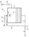
- FIG. 2 is a schematic configuration diagram of the preprocessing unit 100.
- the pretreatment unit 100 of the present embodiment performs degassing treatment on the supplied liquid W.
- the pretreatment unit 100 mainly includes a dewatering vessel 101, a shower head 102, a decompression pump 103, a liquid introduction path 104, a liquid circulation path 105, and a liquid derivation path 106.
- a liquid W such as tap water is supplied to the degassing container 101 from the liquid introduction path 104 via the valve 109.
- the shower head 102 provided in the degassing container 101 atomizes the liquid W and sprays it into the degassing container 101.
- the shower head 102 is for promoting vaporization of the liquid W, but a centrifugal separator or the like can be substituted as a mechanism for producing the vaporization promoting effect.
- the decompression pump 103 When the decompression pump 103 is operated with all valves closed after a certain amount of the liquid W is stored in the dewatering container 101, the vaporized gas component is discharged and dissolved in the liquid W. It also promotes vaporization and discharge of existing gas components. At this time, the internal pressure of the deaeration container 101 may be reduced to about several hundreds to several thousands Pa (1.0 Torr to 10.0 Torr) while checking the pressure gauge 108.
- the gas degassed by the degassing unit 100 includes, for example, nitrogen, oxygen, argon, carbon dioxide and the like.
- the degassing process described above can be repeated for the same liquid W by using the liquid circulation path 105.
- the shower head 102 is operated with the valve 109 of the liquid introduction path 104 and the valve 110 of the liquid discharge path 106 closed and the valve 107 of the liquid circulation path 105 opened.
- the liquid W that has been stored in the degassing container 101 and has been degassed once is sprayed again to the degassing container 101 via the shower head 102.
- the decompression pump 103 the vaporization process by the shower head 102 and the deaeration process by the decompression pump 103 are performed on the same liquid W in an overlapping manner.
- the gas component contained in the liquid W can be gradually reduced.
- the valve 110 is opened to send the liquid W to the dissolution unit 200 via the liquid outlet path 106.
- FIG. 2 shows the degassing unit 100 that vaporizes the melt by lowering the pressure of the gas portion
- the method of degassing the melted liquid is not limited to this.
- a heating and boiling method in which the liquid W is boiled to vaporize the dissolved substance may be adopted, or a membrane deaeration method in which a hollow fiber is used to increase the interface between the liquid and the gas may be adopted.
- the SEPAREL series manufactured by Dainippon Ink and Chemicals, Inc.
- This is used for the purpose of degassing bubbles from the ink mainly supplied to the piezo head by using poly-4-methylpentene-1 (PMP) as a raw material of the hollow fiber membrane.
- PMP poly-4-methylpentene-1
- two or more of a vacuum degassing method, a heating and boiling method, and a membrane degassing method may be used in combination.
- the dissolving unit 200 is a unit that dissolves a desired gas in the liquid W supplied from the pretreatment unit 100.
- the dissolution unit 200 of the present embodiment mainly has a dissolution container 201, a rotary shaft 203 to which a rotating plate 202 is attached, a liquid introduction path 204, a gas introduction path 205, a liquid discharge path 206, and a pressure pump 207.
- the liquid W supplied from the pretreatment unit 100 is supplied and stored in the dissolution container 201 through the liquid introduction path 204.
- the gas G is supplied to the dissolution container 201 through the gas introduction path 205.
- the pressurizing pump 207 is operated to increase the internal pressure of the dissolution container 201 to about 0.5 MPa.
- a safety valve 208 is arranged between the pressure pump 207 and the dissolution container 201. Further, by rotating the rotary plate 202 in the liquid via the rotary shaft 203, the gas G supplied to the dissolution container 201 is bubbled, the contact area with the liquid W is increased, and the gas G is dissolved in the liquid W. Facilitate. Then, such work is continued until the solubility of the gas G reaches almost the maximum saturated solubility. At this time, in order to dissolve as much gas as possible, a means for lowering the temperature of the liquid may be provided. Further, in the case of a gas which is hardly soluble, it is possible to raise the internal pressure of the dissolution container 201 to 0.5 MPa or more. In that case, it is necessary to optimize the material of the container from the viewpoint of safety.
- the liquid W in which the component of the gas G is dissolved at a desired concentration is obtained, the liquid W is discharged via the liquid outlet 206 and supplied to the T-UFB generation unit 300. At this time, the back pressure valve 209 adjusts the flow pressure of the liquid W so that the pressure during supply does not become higher than necessary.
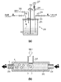
- FIG. 3B is a diagram schematically showing how the gas G mixed in the melting container 201 is melting.
- the bubbles 2 containing the component of the gas G mixed in the liquid W are dissolved from the portion in contact with the liquid W. Therefore, the bubbles 2 gradually contract, and the gas-dissolved liquid 3 exists around the bubbles 2. Since buoyancy acts on the bubble 2, the bubble 2 moves to a position deviated from the center of the gas-dissolved liquid 3 or separates from the gas-dissolved liquid 3 to become a residual bubble 4. That is, in the liquid W supplied to the T-UFB generation unit 300 via the liquid outlet passage 206, the gas-dissolved liquid 3 surrounds the bubbles 2, or the gas-dissolved liquid 3 and the bubbles 2 are separated from each other. The state is mixed.
- the gas-dissolved liquid 3 means “a region in the liquid W where the dissolved concentration of the mixed gas G is relatively high”.
- the concentration is highest around the bubble 2 or in the center of the region even when the gas component is separated from the bubble 2, and the concentration of the gas component becomes continuous as the distance from the position increases. Will be low. That is, in FIG. 3B, the region of the gas-dissolved liquid 3 is surrounded by a broken line for the sake of explanation, but in reality, such a clear boundary does not exist. Further, in the present invention, a gas which is not completely dissolved is allowed to exist in the liquid in the form of bubbles.
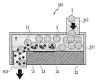
- FIG. 4 is a schematic configuration diagram of the T-UFB generation unit 300.
- the T-UFB generation unit 300 mainly includes a chamber 301, a liquid introduction passage 302, and a liquid discharge passage 303, and a flow from the liquid introduction passage 302 through the chamber 301 toward the liquid discharge passage 303 is a flow pump (not shown). Is formed by.
- As the flow pump various pumps such as a diaphragm pump, a gear pump and a screw pump can be adopted.
- the liquid W introduced from the liquid introduction path 302 contains the gas-dissolved liquid 3 of the gas G mixed by the dissolution unit 200.
- the element substrate 12 provided with the heating element 10 is arranged on the bottom surface of the chamber 301.
- bubbles 13 hereinafter, also referred to as film boiling bubble 13
- an ultra fine bubble (UFB11) containing the gas G is generated.
- UFB11 ultra fine bubble
- FIGS. 5A and 5B are diagrams showing the detailed structure of the heating element 10.
- 5A is a cross-sectional view of the vicinity of the heating element 10
- FIG. 5B is a cross-sectional view of the element substrate 12 in a wider area including the heating element 10.
- a thermal oxide film 305 as a heat storage layer and an interlayer film 306 also serving as a heat storage layer are laminated on the surface of a silicon substrate 304. ..
- a SiO2 film or a SiN film can be used.
- a resistance layer 307 is formed on the surface of the interlayer film 306, and a wiring 308 is partially formed on the surface of the resistance layer 307.
- an Al alloy wiring such as Al, Al—Si, or Al—Cu can be used.
- a protective layer 309 made of a SiO 2 film or a Si 3 N 4 film is formed on the surfaces of the wiring 308, the resistance layer 307, and the interlayer film 306.
- a portion of the surface of the protective layer 309 corresponding to the heat acting portion 311 which eventually becomes the heating element 10 and its surroundings are protected from chemical and physical shocks due to heat generation of the resistance layer 307.
- An anti-cavitation film 310 is formed to protect the film.
- a region on the surface of the resistance layer 307 where the wiring 308 is not formed is a heat acting portion 311 where the resistance layer 307 generates heat.
- the heat generating portion of the resistance layer 307 where the wiring 308 is not formed functions as the heat generating element (heater) 10.
- the layers in the element substrate 12 are sequentially formed on the surface of the silicon substrate 304 by the semiconductor manufacturing technique, and thus the silicon substrate 304 is provided with the heat acting portion 311.
- the configuration shown in the figure is an example, and other various configurations can be applied.
- a structure in which the stacking order of the resistance layer 307 and the wiring 308 is reversed and a structure in which an electrode is connected to the lower surface of the resistance layer 307 can be applied. That is, as will be described later, any structure may be used as long as the liquid can be heated by the heat acting unit 311 to cause film boiling in the liquid.
- FIG. 5B is an example of a cross-sectional view of a region including a circuit connected to the wiring 308 on the element substrate 12.
- An N-type well region 322 and a P-type well region 323 are partially provided on the surface layer of the silicon substrate 304 which is a P-type conductor.
- the P-MOS 320 is formed in the N-type well region 322 and the N-MOS 321 is formed in the P-type well region 323 by introducing and diffusing impurities such as ion implantation by a general MOS process.
- the P-MOS 320 is composed of a source region 325 and a drain region 326 formed by partially introducing N-type or P-type impurities into the surface layer of the N-type well region 322, a gate wiring 335, and the like.
- the gate wiring 335 is deposited on the surface of the portion of the N-type well region 322 excluding the source region 325 and the drain region 326 via the gate insulating film 328 having a thickness of several hundred ⁇ .
- the N-MOS 321 is composed of a source region 325 and a drain region 326 formed by partially introducing N-type or P-type impurities into the surface layer of the P-type well region 323, a gate wiring 335, and the like.
- the gate wiring 335 is deposited on the surface of the portion of the P-type well region 323 excluding the source region 325 and the drain region 326 via a gate insulating film 328 having a thickness of several hundred ⁇ .
- the gate wiring 335 is made of polysilicon with a thickness of 3000 ⁇ to 5000 ⁇ deposited by the CVD method.
- the P-MOS 320 and the N-MOS 321 form a C-MOS logic.
- An N-MOS transistor 330 for driving an electrothermal conversion element (heating resistance element) is formed in a portion of the P-type well region 323 different from the N-MOS 321.
- the N-MOS transistor 330 is composed of a source region 332 and a drain region 331 partially formed in the surface layer of the P-type well region 323 by steps such as impurity introduction and diffusion, and a gate wiring 333 and the like.
- the gate wiring 333 is deposited on the surface of the P-type well region 323 except the source region 332 and the drain region 331 via the gate insulating film 328.
- the N-MOS transistor 330 was used as the driving transistor of the electrothermal conversion element.
- the driving transistor may be any transistor as long as it has a capability of individually driving a plurality of electrothermal conversion elements and can obtain the above-described fine structure. Not limited.
- the electrothermal conversion element and the driving transistor thereof are formed on the same substrate, but they may be formed on different substrates.
- An oxide film isolation region 324 is formed between the P-MOS 320 and the N-MOS 321, and between the elements such as the N-MOS 321 and the N-MOS transistor 330 by field oxidation with a thickness of 5000 ⁇ to 10000 ⁇ . ing. Each element is isolated by this oxide film isolation region 324. In the oxide film isolation region 324, a portion corresponding to the heat acting portion 311 functions as the first heat storage layer 334 on the silicon substrate 304.
- an interlayer insulating film 336 made of a PSG film or a BPSG film having a thickness of about 7,000 ⁇ is formed by the CVD method.
- an Al electrode 337 to be a first wiring layer is formed through a contact hole penetrating the interlayer insulating film 336 and the gate insulating film 328.
- an interlayer insulating film 338 made of a SiO 2 film having a thickness of 10,000 ⁇ to 15,000 ⁇ is formed by the plasma CVD method.
- a resistance layer 307 made of a TaSiN film having a thickness of about 500 ⁇ is formed by a co-sputtering method on a portion corresponding to the heat acting portion 311 and the N-MOS transistor 330.
- the resistance layer 307 is electrically connected to the Al electrode 337 near the drain region 331 via the through hole formed in the interlayer insulating film 338.
- Al wiring 308 is formed as a second wiring layer to be wiring to each electrothermal conversion element.
- the wiring 308, the resistance layer 307, and the protective layer 309 on the surface of the interlayer insulating film 338 are made of a 3000 ⁇ -thick SiN film formed by the plasma CVD method.
- the anti-cavitation film 310 deposited on the surface of the protective layer 309 is at least one metal selected from Ta, Fe, Ni, Cr, Ge, Ru, Zr, Ir, etc., and has a thickness of about 2000 ⁇ . Consists of.
- As the resistance layer 307 various materials such as TaN0.8, CrSiN, TaAl, WSiN other than TaSiN described above can be applied as long as they can cause film boiling in the liquid.
- FIG. 6A and 6B are diagrams showing the state of film boiling when a predetermined voltage pulse is applied to the heating element 10.
- the horizontal axis represents time.
- the vertical axis of the lower graph shows the voltage applied to the heating element 10
- the vertical axis of the upper graph shows the volume and the internal pressure of the film boiling bubble 13 generated by the film boiling.
- FIG. 6B shows the state of the film boiling bubble 13 in association with the timings 1 to 3 shown in FIG. 6A.
- each state will be described in chronological order.
- the UFB 11 generated by the film boiling mainly occurs near the surface of the film boiling bubble 13.
- the UFB 11 generated in the generation unit 300 is supplied again to the dissolution unit 200 via the circulation path, and the liquid is again supplied to the liquid passage of the generation unit 300.
- the supplied state is shown.
- film boiling bubbles 13 Approximately atmospheric pressure is maintained in the chamber 301 before the voltage is applied to the heating element 10.
- film boiling bubbles 13 When a voltage is applied to the heating element 10, film boiling occurs in the liquid in contact with the heating element 10, and the generated bubbles (hereinafter referred to as film boiling bubbles 13) expand due to the high pressure acting from the inside (timing 1). ..
- the foaming pressure at this time is considered to be about 8 to 10 MPa, which is a value close to the saturated vapor pressure of water.
- the voltage application time (pulse width) is about 0.5 usec-10.0 usec, but the film boiling bubble 13 expands due to the inertia of the pressure obtained at timing 1 even after the voltage is no longer applied.
- the negative pressure generated due to the expansion gradually increases, and acts in a direction of contracting the film boiling bubble 13.
- the volume of the film boiling bubble 13 becomes maximum at the timing 2 when the inertial force and the negative pressure are balanced, and thereafter, the film boiling bubble 13 rapidly contracts due to the negative pressure.
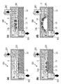
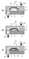
- FIGS. 7A to 7D are diagrams schematically showing how the UFB 11 is generated as the film boiling bubble 13 is generated and expanded.
- FIG. 7A shows a state before the voltage pulse is applied to the heating element 10. Inside the chamber 301, the liquid W in which the gas-dissolved liquid 3 is mixed flows.
- FIG. 7B shows a state in which a film boiling bubble 13 is uniformly generated in almost the entire area of the heating element 10 in contact with the liquid W when a voltage is applied to the heating element 10.
- a voltage is applied, the surface temperature of the heating element 10 rapidly rises at a rate of 10° C./ ⁇ sec or more, and when the temperature reaches almost 300° C., film boiling occurs and film boiling bubbles 13 are generated.
- the surface temperature of the heating element 10 still rises to about 600 to 800° C. during the application of the pulse, and the liquid around the film boiling bubble 13 is also rapidly heated.
- a region of the liquid that is located around the film boiling bubble 13 and is rapidly heated is shown as an unfoamed high temperature region 14.
- the gas-dissolved liquid 3 contained in the unfoamed high-temperature region 14 exceeds the thermal dissolution limit and precipitates to become UFB.
- the diameter of the deposited bubbles is about 10 nm to 100 nm and has a high gas-liquid interface energy. Therefore, it does not disappear in a short time and floats in the liquid W while maintaining its independence.
- the bubbles generated by the thermal action at the time of expansion of the film boiling bubbles 13 as described above are referred to as a first UFB 11A.
- FIG. 7C shows a process in which the film boiling bubble 13 expands. Even when the application of the voltage pulse to the heating element 10 is completed, the film boiling bubble 13 continues to expand due to the inertia of the force obtained when it is generated, and the unfoamed high temperature region 14 also moves and diffuses due to the inertia. That is, in the process in which the film boiling bubble 13 expands, the gas-dissolved liquid 3 contained in the unfoamed high temperature region 14 newly deposits as a bubble and becomes the first UFB 11A.
- FIG. 7D shows a state in which the film boiling bubble 13 has the maximum volume.
- the film boiling bubble 13 expands due to inertia, but the negative pressure inside the film boiling bubble 13 gradually increases with the expansion, and acts as a negative pressure to shrink the film boiling bubble 13. Then, when the negative pressure is balanced with the inertial force, the volume of the film boiling bubble 13 becomes maximum, and thereafter, the film boiling bubble 13 contracts.
- FIGS. 8A to 8C are diagrams showing how the UFB 11 is generated as the film boiling bubble 13 contracts.
- FIG. 8A shows a state in which the film boiling bubble 13 starts contracting. Even if the film boiling bubble 13 starts contracting, the surrounding liquid W still has an inertial force in the expanding direction. Therefore, an inertial force acting in a direction away from the heat generating element 10 and a force toward the heat generating element 10 due to the contraction of the film boiling bubble 13 act on the extreme surroundings of the film boiling bubble 13 to form a decompressed region. Become. In the figure, such a region is shown as an unfoamed negative pressure region 15.
- the gas-dissolved liquid 3 contained in the non-foaming negative pressure region 15 exceeds the pressure dissolution limit and precipitates as bubbles.
- the diameter of the deposited bubble is about 100 nm, and thereafter, the bubble does not disappear in a short time and floats in the liquid W while maintaining its independence.
- the bubbles thus deposited by the pressure action when the film boiling bubble 13 contracts are referred to as the second UFB 11B.
- FIG. 8B shows a process in which the film boiling bubble 13 contracts.
- the speed at which the film boiling bubble 13 contracts is accelerated by the negative pressure, and the unfoamed negative pressure region 15 also moves as the film boiling bubble 13 contracts. That is, in the process of contraction of the film boiling bubble 13, the gas-dissolved liquid 3 at the place where the unfoamed negative pressure region 15 passes is deposited one after another to become the second UFB 11B.
- FIG. 8C shows a state immediately before the film boiling bubble 13 disappears.
- the moving speed of the surrounding liquid W also increases due to the accelerated contraction of the film boiling bubble 13, a pressure loss occurs due to the flow path resistance in the chamber 301.
- the area occupied by the unfoamed negative pressure area 15 becomes larger, and a large number of second UFB 11B are generated.
- FIGS. 9A to 9C are diagrams showing how UFB is generated by reheating the liquid W when the film boiling bubble 13 is contracted.
- FIG. 9A shows a state in which the surface of the heating element 10 is covered with the shrinking film boiling bubbles 13.
- FIG. 9( b) shows a state in which the film boiling bubble 13 contracts and a part of the surface of the heating element 10 is in contact with the liquid W. At this time, even if the liquid W comes in contact with the surface of the heat generating element 10, heat that does not reach the film boiling remains.
- the region of the liquid heated by coming into contact with the surface of the heating element 10 is shown as the unfoamed reheating region 16. Although it does not reach film boiling, the gas-dissolved liquid 3 contained in the unfoamed reheating region 16 is deposited beyond the thermal dissolution limit.
- the bubble generated by reheating the liquid W when the film boiling bubble 13 contracts in this manner is referred to as a third UFB 11C.
- FIG. 9( c) shows a state in which the film boiling bubble 13 has further contracted.
- FIGS. 10A and 10B are diagrams showing a state in which UFB is generated by an impact (a kind of so-called cavitation) at the time of defoaming the film boiling bubble 13 generated by the film boiling.
- FIG. 10A shows a state immediately before the film boiling bubble 13 disappears.
- the film boiling bubble 13 is abruptly contracted by the negative pressure inside, and the unfoamed negative pressure region 15 covers the periphery thereof.
- FIG. 10( b) shows the state immediately after the film boiling bubble 13 disappears at the point P.
- the impact causes the acoustic wave to spread concentrically starting from the point P.
- the acoustic wave is a general term for elastic waves that propagate regardless of gas, liquid, or solid, and in the present embodiment, the density of the liquid W, that is, the high-pressure surface 17A and the low-pressure surface 17B of the liquid W alternately propagate. To be done.
- the gas-dissolved liquid 3 contained in the unfoamed negative pressure region 15 is resonated by the shock wave when the film boiling bubble 13 is defoamed, and undergoes a phase transition exceeding the pressure dissolution limit at the timing when the low pressure surface 17B passes. .. That is, simultaneously with the disappearance of the film boiling bubble 13, a large number of bubbles are deposited in the unfoamed negative pressure region 15.
- the bubble generated by the shock wave when the film boiling bubble 13 is defoamed is referred to as a fourth UFB 11D.
- the diameter is sufficiently smaller than the first to third UFB, and the gas-liquid interface energy is higher than that of the first to third UFB. Therefore, it is considered that the fourth UFB 11D has different properties from those of the first to third UFBs 11A to 11C and produces different effects.
- the fourth UFB 11D is uniformly generated everywhere in the concentric spherical region where the shock wave propagates, it will be uniformly present in the chamber 301 from the time of generation. At the timing when the fourth UFB 11D is generated, a large number of first to third UFBs already exist, but the presence of these first to third UFBs does not significantly affect the generation of the fourth UFB 11D. Absent. Further, it is considered that the first to third UFBs will not disappear due to the generation of the fourth UFB 11D.
- the UFB 11 is generated in a plurality of stages until the film boiling bubble 13 is generated and extinguished by the heat generation of the heating element 10.
- the first UFB 11A, the second UFB 11B, and the third UFB 11C are generated near the surface of the film boiling bubble generated by the film boiling.
- the vicinity is a region within about 20 ⁇ m from the surface of the film boiling bubble.
- the fourth UFB 11D is generated in a region where a shock wave generated when the bubbles are defoamed (disappeared) propagates.
- UFB can be generated even when the film boiling bubble 13 is not exhausted by communicating with the atmosphere before the generated film boiling bubble 13 is defoamed.
- the first UFB 11A described with reference to FIGS. 7A to 7C and the third UFB 11C described with reference to FIGS. 9A to 9C are the thermal dissolution characteristics of such a gas. It can be said that it is a UFB generated by using.
- the higher the liquid pressure, the higher the gas dissolution property, and the lower the pressure the lower the dissolution property. That is, as the pressure of the liquid is lower, the phase transition of the gas-dissolved liquid dissolved in the liquid to the gas is promoted, and UFB is more likely to be generated. When the pressure of the liquid drops from normal pressure, the dissolution characteristics suddenly drop and UFB starts to be generated. Then, the lower the pressure is, the lower the pressure dissolution characteristic is, and the more UFB is produced.
- the second UFB 11B described with reference to FIGS. 8A to 8C and the fourth UFB 11D described with reference to FIGS. 10A to 10C are the pressure dissolution characteristics of such a gas. It can be said that it is a UFB generated by using.
- the first to fourth UFBs with different factors to be generated have been explained individually, but the above-mentioned factors to be generated occur simultaneously with the phenomenon of film boiling. Therefore, at least two types of UFBs among the first to fourth UFBs may be simultaneously generated, and these generation factors may cooperate with each other to generate the UFBs. However, it is common that all of the factors are caused by the volume change of the film boiling bubble generated by the film boiling phenomenon.
- a method of generating UFB by utilizing the film boiling accompanied by the rapid heat generation is referred to as a T-UFB (Thermal-Ultra Fine Bubble) generation method.
- T-UFB Thermal-Ultra Fine Bubble
- UFB generated by the T-UFB generation method is referred to as T-UFB
- a liquid containing T-UFB generated by the T-UFB generation method is referred to as a T-UFB-containing liquid.
- T-UFB generation method Most of the bubbles generated by the T-UFB generation method are 1.0 ⁇ m or less, and it is difficult to generate millibubbles and microbubbles. That is, according to the T-UFB generation method, UFB is dominantly and efficiently generated. Further, T-UFB produced by the T-UFB production method has a higher gas-liquid interface energy than UFB produced by the conventional method, and does not easily disappear as long as it is stored at room temperature and atmospheric pressure. Further, even if new T-UFB is generated by new film boiling, the T-UFB generated in advance is suppressed from disappearing due to the impact.
- the concentration of T-UFB contained in the T-UFB-containing liquid can be adjusted by controlling the number of heating elements arranged in the T-UFB generation unit 300 and the number of times voltage pulses are applied to the heating elements. ..
- the T-UFB producing liquid 300 having a desired UFB concentration is produced in the T-UFB producing unit 300, the UFB containing liquid W is supplied to the post-treatment unit 400.
- FIGS. 11A to 11C are diagrams showing a configuration example of the post-processing unit 400 of the present embodiment.
- the post-treatment unit 400 of the present embodiment sequentially removes impurities contained in the UFB-containing liquid W in the order of inorganic ions, organic substances, and insoluble solid substances.
- FIG. 11A shows a first post-treatment mechanism 410 for removing inorganic ions.
- the first post-treatment mechanism 410 includes an exchange container 411, a cation exchange resin 412, a liquid introduction passage 413, a water collecting pipe 414 and a liquid outlet passage 415.
- a cation exchange resin 412 is housed in the exchange container 411.
- the UFB-containing liquid W generated by the T-UFB generation unit 300 is injected into the exchange container 411 via the liquid introduction path 413 and absorbed by the cation exchange resin 412, where cations as impurities are removed.
- impurities include metal materials and the like exfoliated from the element substrate 12 of the T-UFB generation unit 300, and examples thereof include SiO 2 , SiN, SiC, Ta, Al 2 O 3 , Ta 2 O 5 , and Ir.
- the cation exchange resin 412 is a synthetic resin in which a functional group (ion exchange group) is introduced into a polymer matrix having a three-dimensional network structure, and the synthetic resin has spherical particles of about 0.4 to 0.7 mm.
- a styrene-divinylbenzene copolymer is generally used as the polymer matrix, and methacrylic acid-based and acrylic acid-based copolymers can be used as the functional groups.
- the above materials are examples. The above materials can be variously modified as long as the desired inorganic ions can be effectively removed.
- the UFB-containing liquid W which has been absorbed by the cation exchange resin 412 and the inorganic ions have been removed, is collected by the water collecting pipe 414 and sent to the next step via the liquid outlet passage 415.
- FIG. 11B shows a second post-treatment mechanism 420 for removing organic substances.
- the second post-treatment mechanism 420 includes a container 421, a filtration filter 422, a vacuum pump 423, a valve 424, a liquid introduction passage 425, a liquid discharge passage 426, and an air suction passage 427.
- the inside of the storage container 421 is divided into two upper and lower regions by a filtration filter 422.
- the liquid introduction path 425 is connected to the upper area of the two upper and lower areas, and the air suction path 427 and the liquid outlet path 426 are connected to the lower area.
- the impurities removed by the filtration filter 422 include organic materials that can be mixed in the tube and each unit, such as organic compounds containing silicon, siloxane, and epoxy.
- Examples of the filter film that can be used as the filtration filter 422 include a sub- ⁇ m mesh filter that can remove even bacterial systems and a nm mesh filter that can remove even viruses.
- the vacuum pump 423 is stopped and the valve 424 is opened, the T-UFB-containing liquid in the storage container 421 is sent to the next step via the liquid outlet path 426.
- the vacuum filtration method is adopted here as a method for removing impurities of an organic substance, a gravity filtration method or pressure filtration can also be adopted as a filtration method using a filter.
- FIG. 11C shows a third post-treatment mechanism 430 for removing insoluble solid matter.
- the third post-treatment mechanism 430 includes a precipitation container 431, a liquid introduction passage 432, a valve 433, and a liquid discharge passage 434.
- a predetermined amount of the UFB-containing liquid W is stored in the settling container 431 through the liquid introduction path 432 and left for a while.
- the solid matter contained in the UFB-containing liquid W settles on the bottom of the settling container 431 due to gravity.
- relatively large-sized bubbles such as micro bubbles float on the liquid surface by buoyancy and are removed from the UFB-containing liquid.
- the valve 433 is opened after a sufficient time has passed, the UFB-containing liquid W from which solids and large-sized bubbles have been removed is sent to the recovery unit 500 via the liquid outlet passage 434.
- the present invention is not limited to this, and any post-processing mechanism may be adopted as needed.
- the T-UFB-containing liquid W from which impurities have been removed by the post-treatment unit 400 may be sent to the recovery unit 500 as it is, but may be returned to the dissolution unit 200 again.
- the dissolved gas concentration of the T-UFB-containing liquid W lowered by the generation of T-UFB can be replenished to the saturated state in the dissolution unit 200.
- the UFB-containing concentration of the T-UFB-containing liquid can be further increased under the above-mentioned characteristics.
- the UFB-containing concentration can be increased by the number of circulations of the dissolving unit 200, the T-UFB generating unit 300, and the post-treatment unit 400, and after the desired UFB-containing concentration is obtained, the UFB-containing liquid W Can be sent to the recovery unit 500.
- the collection unit 500 collects and stores the UFB-containing liquid W sent from the post-treatment unit 400.
- the T-UFB-containing liquid recovered by the recovery unit 500 becomes a highly pure UFB-containing liquid from which various impurities have been removed.
- the UFB-containing liquid W may be classified according to the size of the T-UFB by performing several stages of filtering processing. Further, since the T-UFB-containing liquid W obtained by the T-UFB method is expected to be higher in temperature than room temperature, the recovery unit 500 may be provided with a cooling means. In addition, such a cooling unit may be provided in a part of the post-processing unit 400.
- the above is the outline of the UFB generation device 1. However, it is needless to say that it is not necessary to prepare all of the plurality of units as shown in the figure. Depending on the type of liquid W or gas G to be used and the purpose of use of the T-UFB-containing liquid to be generated, some of the above-mentioned units may be omitted, or another unit may be added in addition to the above-mentioned units. You may.
- the degassing unit 100 and the melting unit 200 can be omitted.
- the dissolution unit 200 may be further added.
- the units for removing impurities as shown in FIGS. 11A to 11C may be provided upstream of the T-UFB generation unit 300, or may be provided both upstream and downstream. ..
- the liquid supplied to the UFB generation device is tap water, rainwater, contaminated water, or the like
- the liquid may contain organic or inorganic impurities.
- the heating element 10 may be deteriorated or a salting out phenomenon may be caused.
- liquid W that can be used to generate the T-UFB-containing liquid
- the liquid W that can be used in the present embodiment include pure water, ion-exchanged water, distilled water, physiologically active water, magnetically activated water, lotion, tap water, seawater, river water, water and sewage, lake water, groundwater, Examples include rainwater.
- a mixed liquid containing these liquids can be used.
- a mixed solvent of water and a water-soluble organic solvent can also be used.
- the water-soluble organic solvent used by mixing with water is not particularly limited, but specific examples include the following.
- Alkyl alcohols having 1 to 4 carbon atoms such as methyl alcohol, ethyl alcohol, n-propyl alcohol, isopropyl alcohol, n-butyl alcohol, sec-butyl alcohol and tert-butyl alcohol.
- Amides such as N-methyl-2-pyrrolidone, 2-pyrrolidone, 1,3-dimethyl-2-imidazolidinone, N,N-dimethylformamide and N,N-dimethylacetamide.
- Ketones such as acetone and diacetone alcohol, or keto alcohols.
- Cyclic ethers such as tetrahydrofuran and dioxane. Ethylene glycol, 1,2-propylene glycol, 1,3-propylene glycol.
- Polyalkylene glycols such as polyethylene glycol and polypropylene glycol.
- Triols such as glycerin, 1,2,6-hexanetriol and trimethylolpropane. These water-soluble organic solvents may be used alone or in combination of two or more.
- gas components that can be introduced in the dissolution unit 200 include hydrogen, helium, oxygen, nitrogen, methane, fluorine, neon, carbon dioxide, ozone, argon, chlorine, ethane, propane, air, and the like. Also, a mixed gas containing some of the above may be used. Further, the dissolving unit 200 does not necessarily have to dissolve a substance in a gas state, and a liquid or solid composed of a desired component may be melted in the liquid W.
- the dissolution in this case may be natural dissolution, dissolution by applying pressure, or dissolution accompanied by hydration by ionization, ionization, and chemical reaction.
- buoyancy acts on relatively large-sized bubbles such as millibubbles and microbubbles, and they eventually float to the liquid surface and disappear.
- UFB on which buoyancy does not act, does not have such a large gas-liquid interface energy, and therefore may disappear along with millibubbles and microbubbles.
- the number of UFBs corresponding to the number of repetitions cannot be stored for a long period of time. That is, in the UFB-containing liquid produced by the conventional UFB producing method, it was difficult to maintain the UFB-containing concentration at a predetermined value for a long time.
- the T-UFB generation method of the present embodiment using film boiling a rapid change in temperature from room temperature to about 300° C. and a sudden change in pressure from normal pressure to about several megapascals can be performed. Is generated locally in the immediate vicinity of.
- the heating element has a quadrilateral shape with one side of about several tens ⁇ m to several hundreds ⁇ m. Compared with the size of the conventional UFB generator, it is about 1/10 to 1/1000.
- the gas-dissolved liquid existing in the extremely thin film region of the film boiling bubble surface momentarily exceeds the thermal or pressure dissolution limit (in an extremely short time of microsecond or less), and a phase transition occurs. It becomes UFB and precipitates.
- the liquid contains UFB having a diameter of about 100 nm with extremely high purity. Furthermore, since the T-UFB thus produced has a sufficiently high gas-liquid interface energy, it is difficult to be destroyed in a normal environment and can be stored for a long period of time.
- the interface is formed in a part of the liquid existing in the vicinity of the heating element without affecting the entire liquid region. It is possible to make the region that acts thermally and pressure associated therewith extremely local. As a result, the desired UFB can be stably generated. Further, by circulating the liquid and further applying the UFB generation condition to the generated liquid, it is possible to additionally generate a new UFB with less influence on the existing UFB. As a result, a UFB liquid having a desired size and concentration can be manufactured relatively easily.
- the T-UFB generation method has the above-mentioned hysteresis characteristic, the content concentration can be increased to a desired concentration while maintaining high purity. That is, according to the T-UFB production method, it is possible to efficiently produce a UFB-containing liquid having high purity, high concentration and capable of being stored for a long period of time.
- T-UFB-containing liquid ⁇ Specific application of T-UFB-containing liquid>
- the application of the ultrafine bubble-containing liquid is distinguished depending on the type of gas contained therein.
- any gas can be converted into UFB as long as it is a gas that can dissolve PPM to BPM in the liquid in the liquid.
- it can be applied to the following uses.
- the UFB-containing liquid containing air can be suitably used for cleaning industrial, agricultural and marine industries, medical purposes, etc., and growing plants and agricultural and marine products.
- ⁇ UFB-containing liquid containing ozone is suitable for cleaning purposes such as industrial, agricultural and marine industries and medical purposes, as well as for purposes such as sterilization, sterilization and sterilization, and for environmental purification of drainage and contaminated soil. Can be used.
- ⁇ UFB-containing liquid containing nitrogen is suitable for cleaning purposes such as industrial, agricultural and marine industries and medical purposes, as well as for purposes such as sterilization, sterilization and sterilization, and for environmental purification of drainage and contaminated soil. be able to.
- the UFB-containing liquid containing oxygen can be suitably used not only for cleaning purposes such as industrial, agricultural and marine industries, and medical purposes, but also for growing plants and agricultural and marine products.
- the UFB-containing liquid containing carbon dioxide can be suitably used not only for cleaning purposes such as industrial, agricultural and fisheries industries, medical purposes, but also for purposes such as sterilization, sterilization and sterilization.
- the UFB-containing liquid containing perfluorocarbon which is a medical gas, can be suitably used for ultrasonic diagnosis and treatment.
- the UFB-containing liquid can exert effects in various fields such as medical treatment, medicine, dentistry, food, industry, agriculture and fisheries.
- the purity and concentration of UFB contained in the UFB-containing liquid are important in order to quickly and reliably exert the effect of the UFB-containing liquid. That is, by using the T-UFB production method of the present embodiment capable of producing a UFB-containing liquid with high purity and a desired concentration, it is possible to expect further effects in various fields.
- the T-UFB producing method and the uses for which the T-UFB-containing liquid is supposed to be suitably applied are listed.
- T-UFB generation unit in the humidifier, aroma diffuser, coffee maker, etc., it can be expected to improve the indoor humidifying effect, deodorizing effect, and scent diffusion effect.
- T-UFB generation unit in the seawater or freshwater supply route for aquaculture at aquaculture locations such as fish and pearls, it can be expected to promote spawning and development of seafood.
- T-UFB in the liquid fuel of equipment (vehicles, ships, airplanes, etc.) that uses liquid fuel.
- T-UFB-containing liquid when cleaning and maintaining the parts manufactured in the factory such as the deburring process after pressing.
- the polishing effect can be improved by using the T-UFB-containing liquid as the polishing water for the wafer when manufacturing the semiconductor element. Further, in the resist removing step, it is expected that the use of the T-UFB-containing liquid will promote the peeling of the resist which is difficult to peel off.
- the cleaning effect and disinfection effect of these equipment can be improved. Can be expected. It can also be applied to the treatment of living things.
- HIFU High Intensity Focused Ultrasound
- T-UFB-containing high-concentration nanobubbles as a seed, phospholipids forming liposomes are modified in the negatively charged region around the bubbles, and various medical substances (DNA, RNA, etc.) are mediated by the phospholipids. It is possible to prepare a nanobubble formulation to which is added.
- ⁇ A As a dental pulp or dentin regeneration treatment, when a drug containing high-concentration nanobubble water generated by T-UFB is delivered into the dental canal, the drug penetrates deeply into the dentinal tubule due to the permeation action of nanobubble water to promote the sterilization effect, It is possible to treat infected root canals of the dental pulp quickly and safely.
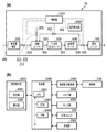
- FIG. 12A is a diagram showing a schematic configuration of the UFB generation device 1A in this embodiment.
- the UFB generation device 1A shown here includes a pretreatment device 100, a lysing unit 200, a T-UFB generation unit 300, a post-treatment unit 400, and a recovery unit 500, similar to those shown in the above-mentioned basic configuration.
- the UFB generation device 1A according to the present embodiment is provided with the reflux path 420 that guides the UFB-containing liquid generated in the post-treatment unit 400 to the dissolution unit 200.
- the liquid outlet passage 434 see FIG.
- one end of the reflux passage 420 is connected to the upstream side of the outlet valve 433, and the other end of the reflux passage 420 is connected to the dissolution unit 200. It is connected to the dissolution vessel 201 (see FIG. 3). Further, the circulation path 420 is provided with a circulation valve 421 for switching between communication and cutoff of the path 420.
- 210 is a gas introduction valve provided in the gas introduction passage 205 of the dissolution unit 200
- 211 is a liquid introduction valve provided in the liquid introduction passage 204 provided in the liquid introduction passage 204 of the dissolution unit 200.
- 211 is shown.
- these valves 210 and 211 are collectively referred to as an introduction valve 212.
- the introduction valve 212, the derivation valve 433, and the circulation valve 421 are controlled by the control unit 1000 described below.
- the circulation path as the liquid path by closing the introduction valve 212 and the derivation valve 433 and opening the circulation valve 421. That is, it is possible to configure a circulation path for returning the liquid of the dissolution unit 200 to the dissolution unit 200 again via the T-UFB generation unit 300, the post-treatment unit 400, and the reflux path 420.
- FIG. 12B is a diagram showing a schematic configuration of a control system of the UFB generation device 1A in this embodiment.
- the control unit 1000 includes, for example, a CPU 1001, a ROM 1002, a RAM 1003, and the like.
- the CPU 1001 functions as a control unit that totally controls the entire UFB generation device 1A.
- the ROM 1002 stores control programs executed by the CPU 1001, fixed tables and other fixed data.
- the RAM 1003 has an area for temporarily storing various input data, a work area when the CPU 1001 executes processing, and the like.
- the operation display unit 6000 includes a setting unit 6001 that functions as a setting unit that performs various setting operations including a UFB generation concentration, a UFB generation time, and the like by a user, and a display that displays a UFB-containing liquid generation required time, a device status, and the like. And a display portion 6002 as a means.
- the control unit 1000 controls the heating element driving unit (driving unit) 2000 that drives each heating element 10 of the heating unit 10G having the plurality of heating elements 10 provided on the element substrate 12.
- the heating element drive unit 2000 applies a drive pulse according to a control signal from the CPU 1001 to each of the plurality of heating elements 10 included in the heating unit 10G.
- Each heating element 10 emits heat according to the voltage, frequency, pulse width, etc. of the applied drive pulse.
- the control unit 1000 controls a valve group 3000 including valves provided in each unit.
- the valve group 3000 also includes the above-described introduction valve 212, derivation valve 433, circulation valve 421, and the like.
- the control unit 1000 also controls the pump group 4000 including various pumps provided in the UFB generator and the rotating unit 203 provided in the melting unit 200.
- the T-UFB generation unit 300 is provided with a measurement unit that performs measurement for estimating the UFB concentration of the UFB-containing liquid that is being generated, and the measurement is performed here. The measured value is input to the control unit 1000.
- the rest of the configuration is the same as that of the UFB generation device 1 described above, and a duplicate description will be omitted.
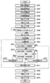
- the target UFB concentration of the UFB-containing liquid is set.
- the number of UFB per 1 mL is set, and the set value is 100 million pieces/mL. Further, the amount of the UFB-containing liquid produced is 1 L (liter).
- the UFB generation speed that is, the drive frequency, which is the number of times of driving the heating element 10 per second.
- the drive frequency of the heating element 10 is set to 10 kHz based on the target UFB concentration.
- the target UFB concentration can be set by the user from the setting unit 6001.
- step S103 the time required to generate the UFB-containing liquid having the UFB concentration set as described above is obtained, and the time required (estimated generation time) is displayed on the display unit 6002.
- This estimated generation time is calculated based on the following generation conditions i) and ii).
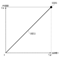
- FIG. 14 is a diagram showing the relationship between the estimated generation time T of UFB calculated in S103 and the UFB concentration of the UFB-containing liquid.
- a straight line 10211 shown in FIG. 14 indicates an estimated value in which the UFB concentration increases with the passage of generation time.
- the outlet valve 433 is closed.
- the circulation valve 421 is opened, and in S106, the introduction valve 212 (the liquid introduction valve 211 and the gas introduction valve 210) is opened.
- the liquid introduction valve 211 the liquid (in this case, water) pretreated by the pretreatment device 100 is introduced into the dissolution unit 200, and the dissolution unit 200 is filled with water.
- the gas introduction valve 210 is opened, the dissolution unit 200 is in a state capable of introducing air.
- the water in which air is dissolved is sent to the T-UFB generating unit 300.
- the liquid sent to the T-UFB generation unit 300 is sent to the post-treatment unit 400 and then to the reflux path 420.
- UFB generation processing is performed.
- the UFB generation process by the heating element 10 is started.
- the driving pulse having the driving frequency set in S102 is applied to each of the 10,000 heating elements 10.
- UFB is generated in the water supplied to the T-UFB generation unit 300.
- a reflux path 420 from the dissolution unit 200 to the dissolution unit 200 via the T-UFB generation unit 300 and the post-treatment unit 400 is circulated in the apparatus. Therefore, while circulating in the reflux path 420, UFB generated in the T-UFB generation unit 300 is mixed with water, and the UFB concentration in the UFB-containing liquid increases.
- the measurement unit 5000 measures the current UFB concentration of the UFB-containing liquid circulating in the reflux path 420.
- the measuring unit there are a measuring method that optically counts the number of UFB in the UFB-containing liquid using a magnifying glass and a camera to measure the UFB concentration, and a method that measures the UFB concentration by measuring the Z potential. Although it is known, any density detection method can be applied.
- S111 it is determined whether the UFB concentration measured in S110 is equal to or higher than the target UFB concentration set in S101. If the determination result is Yes, the process proceeds to S110, and the UFB generation process ends. If the determination result is No, the process proceeds to S112 to further increase the UFB concentration.
- the time required for the UFB concentration of the UFB-containing liquid to reach the target concentration is recalculated, the time required is updated, and the updated time required is displayed.
- the remaining required time for generating the UFB-containing liquid of the target UFB concentration is calculated, and the remaining required time is displayed on the display unit 6002. To do. It should be noted that it is necessary to update the required time in this way, due to temperature and other factors such as water temperature, heating element temperature, device temperature, and environmental temperature outside the device, there is a slight variation in the generation capacity of the UFB generation device 1A. Is caused.
- the UFB concentration (the number of UFB per 1 mL) measured at a time point of about 50 seconds from the start of UFB generation is 4.0e7/mL, reaching the target 1.0e8/mL. The explanation will be given assuming that it is not.
- the T-UFB generation is stopped and the process ends. This is different from the conventional UFB generation method, when the heating element continues to be heated when water on the heating element is lost due to damage to the device container, failure of the water amount detection sensor, etc. Is too high.
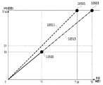
- FIG. 15 is a diagram showing a relationship between the estimated generation time T of UFB calculated in S112 and the UFB concentration of the UFB-containing liquid.
- a broken line 10311 shown in FIG. 15 shows the initial estimated concentration of the UFB-containing liquid, which increases with the passage of generation time.
- the UFB generation process is continued, the process returns to S110 again, the UFB concentration is measured, and the determination process of S111 is performed based on the measured result of the UFB concentration. .. Then, if the determination result in S111 is Yes, the process proceeds to S113 to end the UFB generation process. After that, the circulation valve 421 is closed in S114, and the outlet valve 433 is opened in S115. As a result, the UFB-containing liquid generated from the T-UFB generation unit 300 via the post-treatment unit 400 is discharged to the recovery unit 500. With the above, a series of generation processes of the UFB-containing liquid is completed.
- the production rate of the UFB-containing liquid and the UFB concentration can be controlled with high accuracy.
- the time required to generate a predetermined amount of the UFB-containing liquid having the desired UFB concentration is highly accurately estimated according to the difference between the target UFB concentration and the actual UFB concentration. , Notifies the user of the result. Therefore, the user can grasp the exact required time for the generation time of the UFB-containing liquid.
- the production result is fed back to the subsequent processing to perform control to maintain a constant production amount.
- the process of estimating the required time in S203 is performed on the assumption that 10,000 heating elements 10 are used. However, actually, about 2,000 heating elements among the assumed heating elements 10 are estimated.
- the explanation will be given by taking the case where the fever function is lost as an example.
- the measured UFB concentration at the time when the UFB generation rate is about 50 seconds after the start of UFB generation is not 50 million/mL, but is 40 million/mL as follows.
- the actual UFB generation rate that has been performed so far is calculated as follows based on the UFB concentration measured in S210 and the elapsed time (50 (seconds)) from the start of UFB generation.
- the UFB generation rate that was actually performed was 0.8e9 (units/second), which was 20% less than the initially assumed UFB generation rate of 1.0e9 (units/second). It turns out.
- the above processing is performed in S212.
- the required time is recalculated and displayed.
- the display contents will be updated.
- FIG. 17 is a diagram showing the relationship between the estimated generation time T of UFB calculated in S213 and the UFB concentration of the UFB-containing liquid.
- a broken line 10511 shown in FIG. 17 shows the initial estimated concentration of the UFB-containing liquid that increases along with the passage of generation time.
- the UFB generation process is continued, the process returns to S210 again, the UFB concentration is measured, and the determination process of S211 is performed based on the measurement result of the measured UFB concentration. .. Then, if the determination result of S211 is Yes, the process proceeds to S214, and the UFB generation process ends. After that, the circulation valve 421 is closed in S215, and the outlet valve 433 is opened in S216. As a result, the UFB-containing liquid processed by the T-UFB generation unit 300 and the post-treatment unit 400 is discharged to the recovery unit 500. With the above, a series of generation processes of the UFB-containing liquid is completed.
- the number of heating elements 10 used and the driving frequency are controlled, so that the generation rate and UFB concentration of the UFB-containing liquid can be controlled with high accuracy. Furthermore, in the present embodiment, the actual UFB generation speed can be set with higher accuracy by updating the number of heating elements that can be actually driven using the UFB measurement result. Therefore, it becomes possible to more accurately estimate and notify the time required to generate a desired amount of the UFB-containing liquid having a desired UFB concentration.
- the UFB generation speed set in the previous UFB-containing liquid generation operation can be used to highly accurately estimate the UFB generation time. That is, in the UFB generation rate setting process of S202 in the current generation operation, the number of used heating elements (total of 8,000 heating elements in the above example) updated in S212 of the previous generation operation of the UFB-containing liquid is used. be able to. Therefore, in this generation operation, it is possible to perform highly accurate estimation and display of the required time corresponding to the change in the performance of the UFB generation device 1A in the first required time estimation process (the process of S203).
- Table 1 shows an example of calculating how the time required to achieve the target number of UFB changes according to the number of heat generating elements that can be driven in this embodiment.
- the estimation of the required time in the present embodiment is suitable for the estimation in the case where it is highly likely that the same tendency will be reproduced in the same operation thereafter, that is, the heating element loses the heat generating function.
- the required time of the UFB-containing liquid is recalculated and displayed every 50 seconds in S213, but in the present embodiment also, the required time is recalculated at a shorter time interval. It is possible to display. According to this, it becomes possible to more accurately estimate the time until the target UFB concentration is reached.
- the UFB generation speed and the number of drivable heating elements are estimated based on the elapsed time T from the start of UFB generation and the generated UFB concentration D at that time.
- the above estimation may be performed based on the fluctuation of the device performance in a shorter time.
- the UFB concentration is measured in units of 10 seconds, and the difference between the UFB concentration D at the time when 50 seconds has passed and the UFB concentration D at the time when 40 seconds has passed is estimated to estimate the time when 50 seconds have passed.
- a method of estimating the UFB generation rate by dividing by a time difference of 10 seconds may be used. This method is suitable for estimation in the case where the time required for the fluctuation of the generation capacity of the UFB generation device is shorter than the UFB generation time.
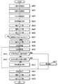
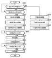
- FIG. 18 is a flowchart showing the UFB-containing liquid generation processing executed according to this embodiment.
- the UFB progress concentration corresponding to the elapsed time is set based on the UFB generation rate set in S303 in the previous UFB-containing liquid generation process.
- the UFB generation rate is 1.0e8 cells/mL
- the estimated value of the progressing UFB concentration at each elapsed time is as shown in Table 2.
- S305 to S312 are the same as S104 to S111 in FIG. 13, so description thereof will be omitted.
- the process proceeds to S313.
- the UFB concentration measured in S311 is compared with the UFB progress concentration set in S304, and it is determined whether the measured UFB concentration has reached the UFB progress concentration. If the determination result is YeS, the process proceeds to S315. In S315, the UFB generation speed is increased, and the process proceeds to S316.
- S313 If the determination result in S313 is No, the process proceeds to S314. In S314, it is determined whether the UFB concentration measured in S311 exceeds the UFB progress concentration set in S304. If the determination result is YeS, the process proceeds to S316. In S316, the UFB generation speed is reduced, and the process proceeds to S317.
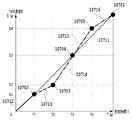
- FIG. 19 is a diagram showing the relationship between the UFB generation time T and the generated UFB concentration D when the UFB generation rate is controlled based on the measured UFB concentration in the present embodiment. It is a figure which shows the relationship between the UFB production
- UFB is generated as originally assumed for 20 seconds (T1) from the start of UFB generation, and after 20 seconds, a part of the heating elements 10 loses the heat generating function and the UFB generation speed decreases.
- T1 20 seconds
- a part of the heating elements 10 loses the heat generating function and the UFB generation speed decreases.
- a solid line 10712 shows the estimated value of the UFB concentration with the generation time.
- the measured value of the UFB concentration is shown.
- the determination result of S313 is YeS and S315 At, the UFB generation rate is increased.
- the UFB generation rate is increased by increasing the drive frequency of the heating element 10.
- the alternate long and short dash line 10714 in FIG. 19 indicates the UFB concentration estimated value over the generation time.
- the dashed-dotted line 10715 in FIG. 19 indicates the UFB concentration estimated value that increases with the generation time.
- the estimated density value is shown.
- the UFB generation rate is reduced by reducing the drive frequency of the heating element 10.
- the two-dot chain line 10716 shown in FIG. The estimated density value is shown.
- the estimated UFB concentration value finally reaches the value indicated by point 10701 in FIG.
- the UFB generation rate can be estimated by measuring the UFB concentration, and the generation rate by the heating element is controlled based on the measurement result of the UFB concentration. For this reason, the actual UFB generation time can be brought closer to the target time, and the UFB concentration control and the required time can be estimated with higher accuracy.
- the UFB generation rate in S315 and S316 is controlled by controlling the drive frequency of the heating element 10 has been shown.
- the method for controlling the UFB generation speed is not limited to the method for controlling the drive frequency, and another control method may be used or a plurality of control methods may be combined.
- Table 3 shows a combination example of the number of drivable heating elements and the UFB generation speed to be used.
- the number of heat generating elements that can be driven tends to decrease due to the loss of the heat generating function of the heat generating elements accompanying the UFB generation operation. Therefore, it is also effective to initially set the condition of using only 8,000 heating elements out of 10,000 heating elements. For example, in S315, 9000 heating elements are used to increase the UFB generation rate, and 10,000 heating elements are used to further increase the UFB generation rate. Also, 7,000 heating elements are used when the UFB generation rate in S316 is reduced, and 6,000 heating elements 10 are used when the UFB generation rate is further reduced. It is also possible to adjust the UFB generation rate according to the number of heating elements used in this way. In the case of performing such control, if the combination of the heating elements to be initialized is sequentially changed for each UFB generation operation, it is possible to make the consumption of the heating elements uniform and to reduce the heat generation. It is possible to extend the life of the element.
- Table 4 shows an example of the combination of the number of driving times (driving frequency) of the heating element per second and the UFB generation speed.
- Table 5 shows an example in which the UFB generation rate (the number of UFB generated per second) is kept constant by the combination of the driving frequency of the heating elements and the number of heating elements.
- the UFB-containing liquid generation apparatus has a function of limiting the UFB concentration to an appropriate concentration when the user sets the target UFB concentration that is too high.
- the UFB-containing liquid generating apparatus of the above-described embodiment using the T-UFB method can hold a gas in a liquid (for example, water) exceeding the saturation solubility. It depends.
- the UFB concentration can be improved only by increasing the generation time, and as a result, a UFB-containing liquid holding a high concentration of gas that has never existed can be generated. It is possible.
- the UFB-containing solution having a high UFB concentration has various effects, but it may reduce the effect on an excessive concentration of UFB. Therefore, the concentration limiting function described below provides an appropriate UFB concentration. It is preferable to limit
- FIG. 20 is a flowchart showing the UFB-containing liquid generation processing executed according to this embodiment.
- S401 to S410 are the same as S101 to S110 in FIG. 13
- S412 to S416 are the same as S111 to S115 in FIG.
- the upper limit UFB concentration is set so as not to allow generation of excessive UFB concentration.
- the setting process of the upper limit UFB concentration is performed by reading the upper limit UFB concentration stored in advance in the RAM or the like. Alternatively, it is possible to set an upper limit value specified by the user from among a plurality of predetermined upper limit values.
- S411 it is determined whether the measured UFB concentration measured in S410 is equal to or higher than the upper limit UFB concentration set in S400. If the determination result is No, the process proceeds to S412 and the process is continued. If the determination result of the determination process of S411 is Yes, the process proceeds to S417. In S417, a warning is given to the user by using a monitor and a warning light. A method of emitting a sound or notifying a warning to another device via the network may be used. After that, the processing of S414 to S416 is performed. This processing is similar to the processing of S113 to S115 in FIG.
- the upper limit UFB concentration set in S400 is preferably set according to the type of gas generated as UFB. Further, instead of setting the upper limit UFB concentration in S400, a warning is given when the set concentration exceeds the upper limit UFB concentration in the setting process of the target UFB concentration performed in S401, and the setting of the target UFB concentration is not permitted. It is also possible to adopt the method.
- the upper limit UFB concentration is set, and when a UFB concentration exceeding the upper limit UFB concentration is detected, a warning is notified and the UFB generation is stopped. This makes it possible to prevent the production of a UFB-containing solution having an excessively high UFB concentration by the T-UFB method.
- the upper limit UFB concentration is preferably set appropriately according to the concentration of the prepared UFB-containing liquid, the working environment, the usage environment of the UFB-containing liquid, and the like.
- the UFB-containing liquid stored in the recovery unit 500 is stored in some closed container, and the UFB-containing liquid is transferred to the place of use. It was supposed to be used from.
- the present invention is not limited to application to the use cases as described above.
- the present invention is also applicable to a use case in which UFB is generated in the liquid supplied from the liquid path by the T-UFB method and the generated UFB-containing liquid is discharged as it is to a predetermined use position.
- T-UFB generation apparatus As a T-UFB generation apparatus to which the present invention is applied in such a use case, a T-UFB generation apparatus used as a water purifier and a T-UFB generation apparatus used in a washing machine will be described as an example. ..
- FIG. 21 is a diagram schematically showing a T-UFB generator used as a water purifier.
- a T-UFB generation device 700 has a T-UFB generation unit 711 (hereinafter, also simply referred to as a unit) attached to the end of a tap for water, and water (liquid ) Is added with UFB to purify tap water.
- the unit 711 includes a liquid detection sensor (liquid detection means) 7111 for detecting the presence or absence of water, a flow velocity sensor (flow velocity detection means) 7112 for detecting the speed of the water flow, and T-UFB for the water flowing into the inside.
- a heat generating part 7113 for generating Further, the unit 711 is provided with a control unit 713 that controls driving of the heat generating unit 7113.
- an operation display unit 712 for setting the operation of the T-UFB is provided on the outer surface of the unit 711.
- the operation display unit 712 is provided with an OFF setting button 7121, a LOW setting button 7122, and a HIGH setting button 7123.
- the OFF setting button is a button for instructing to stop UFB generation
- the LOW setting button 7122 is a button for instructing generation of UFB having a relatively low concentration.
- the HIGH setting button 7123 is a button for instructing the generation of relatively high concentration UFB.
- a light emitting element (not shown) is built in each of the buttons 7121, 7122, 7123.
- the light-emitting element incorporated in each button emits light under drive control of the control unit 713 when the button is in an effective state, and can notify the user of the status of button operation.
- both the liquid detection sensor 7111 and the flow velocity sensor 7112 are connected to the above-mentioned CPU 714, and the detection signal from each sensor is input to the CPU 714.
- reference numeral 7013 indicates a pipe section 7013 of the water supply facility.
- a valve (not shown) is provided in the piping portion 7013, and it is possible to supply, stop, and adjust the supply amount of tap water to the UFB generation unit 711 by adjusting the opening degree of the valve. ..
- the tap water flows in the piping portion 7013 along the directions indicated by arrows 7014 and 7015.
- the liquid detection sensor 7111 detects the presence or absence of water.
- the detection result of the liquid detection sensor 7111 is “no water”, and when the tap water is supplied, the detection result of the liquid detection sensor 7111 is “with water”. Becomes If the detection result is no water, the process of S501 is repeated. If the detection result in S501 is “with water”, the process proceeds to S502.
- the flow velocity sensor 7112 detects the flow velocity of water supplied to the UFB generation unit 711.
- the flow velocity sensor 7112 may employ a mechanical detection method using a water wheel or a spring, or an electrical detection method using pressure.
- the target UFB concentration is set.
- the density is set based on the setting by the operation display unit 712 shown in FIG.
- the UFB generation speed is set.
- the UFB generation rate is set according to the flow rate of the supplied water and the target UFB concentration. That is, in order to achieve the target UFB concentration, it is necessary to increase the UFB generation rate as the flow rate becomes faster.
- -The number of heating elements is 1000.
- the target UFB is controlled by controlling the number of driving times (driving frequency) of the heating element per second. Achieve concentration.
- Table 6 shows a list of each flow velocity, the required UFB generation speed for achieving the target UFB generation concentration on the operation display unit 712, and the number of times the heat generating unit 7113 is driven per second.
- the UFB generation device 700 has 10 (mL/sec) ⁇ 1 million (per second).
- Pieces/mL) 10 million (pieces/second) UFB generation rate is required.
- UFB generation is executed according to the UFB generation speed set in S505. Further, in S506, the UFB generation status is displayed, and the process returns to S502. After that, the processes of S502 to S507 are continued until the determination result of S503 is “supply stop”.
- the operation display unit 712 has a light emitting element built in each of the buttons 7121, 7122, 7123.
- the selected button among these buttons 7121, 7122, 7123 blinks in green to indicate that the UFB is being generated. Further, in a situation where the target UFB concentration cannot be realized because the flow rate of the supplied water is too large, the selected button blinks in red to prompt the user to take a measure such as reducing the flow velocity.
- the reduced flow rate is detected in the next S502, and the UFB generation rate is reset based on the reduced flow rate in S506.
- the emission color of the selected button is changed to green.
- the UFB generation rate is reset in S506 based on the lowered target UFB concentration.
- the button emission color is changed to red by resetting the UFB generation rate in S506. It may change.
- the CPU 714 sets the actual drive count to the required drive count and controls the LOW setting button 7122 to emit green light. ..
- the flow rate exceeds 40 mL/sec
- the number of driving times exceeding the upper limit of 4000 times/sec is required. Therefore, when the flow velocity detected by the flow velocity sensor 7112 exceeds 40 mL/sec, the CPU 714 sets the actual driving count to the upper limit of 4000 times/sec and sets the emission color of the LOW setting button 7122 to red. I do.
- the target UFB concentration can be achieved up to a flow rate of 20 mL/sec. Therefore, when the flow velocity detected by the flow velocity sensor 7112 is 20 mL/sec or less, the CPU 714 sets the actual drive count to the required drive count and controls the HIGH setting button 7123 to emit green light. .. However, when the flow rate exceeds 20 mL/sec, the number of driving times exceeding the upper limit of 4000 times/sec is required. Therefore, when the flow velocity detected by the flow velocity sensor 7112 exceeds 20 mL/sec, the CPU 714 sets the actual driving count to the upper limit of 4000 times/sec, and sets the HIGH setting button 7123 to emit red light.
- the emission color of the OFF setting button 7121 is set to white in order to clearly indicate to the user that the UFB generation is in the OFF state.
- the user can visually recognize whether or not the UFB-containing liquid having the desired UFB concentration has been generated, and whether or not UFB has been generated, by the emission color of the button. Become.
- the operation display unit 712 is provided with a display unit capable of displaying a larger amount of information.
- a liquid crystal display, an organic EL display, or the like may be provided in the operation display unit 712 to display information such as the actual UFB generation concentration.
- a communication unit (not shown) on the UFB generation unit 711, transmit the information such as the actual UFB generation concentration to an external device such as a smartphone, and display the information on the external device side.
- the UFB-containing liquid having the desired UFB concentration it is possible to provide the user with the UFB-containing liquid having the desired UFB concentration by setting the UFB generation rate according to the flow rate. Further, depending on the set flow velocity or UFB concentration, the desired UFB concentration may not be realized in some cases, but in such a case, it is possible to dynamically notify the user of the unrealizable state. ..
- the liquid itself here, tap water
- the flow channel structure can be simplified, and the size and cost of the device can be reduced.
- a conventional UFB generator using a Venturi tube or the like at least two UFB-containing liquids can be switched to a UFB-containing liquid while maintaining the liquid flow. Paths and valves for switching between them are required.
- the water purifier is configured by the T-UFB generator that can obtain a high UFB concentration.
- the T-UFB generator according to the present invention is not limited to the water purifier, and is applied to other UFB generators that require the UFB generation rate to be modulated with respect to the varying flow velocity or desired UFB concentration. Is also effective.
- T-UFB generator installed in washing machine Next, the T-UFB generator installed in the washing machine will be described. Also in the T-UFB generator installed in the washing machine, the configuration in which UFB having a predetermined UFB concentration is stably supplied to the supplied water is the same as that of the T-UFB generator 700 shown in FIG. is there. However, in the T-UFB generation device 800 in this example, it is required to generate a UFB-containing liquid suitable for the function unique to the washing machine. As a function unique to the washing machine, for example, Washing: Remove dirt and other substances from clothing. Bath cleaning: Remove black mold etc. adhering to the laundry tank.
- the UFB-containing liquid having UFB concentrations corresponding to these functions is supplied from the T-UFB generator to improve each function of the washing machine.
- the configuration and operation of the T-UFB generator used in the washing machine will be described below with reference to FIGS. 23 and 24.
- the washing machine 8000 shown in FIG. 23 is equipped with a T-UFB generator 800 on the water supply side, and uses the UFB-containing liquid generated here to wash clothes and wash the inside of a washing tub.
- a washing machine body 8300 of the washing machine 8000 is provided with a washing tub 8301.
- the washing tub 8301 is connected to a T-UFB generator 800, which will be described later, that is connected to the water supply route 8303, and a drainage route 8305 that discharges the water in the washing tub 8301 to the outside.
- the washing tub 8301 is connected to a reflux path 8304 for circulating water between the washing tub 8301 and the T-UFB generator 800, and a filter 8302 for removing foreign matter is provided at the outlet of the reflux path 8304.
- arrows 8307 to 8309 in the figure indicate the directions of the water flow in each path.
- the main body 8300 of the washing machine is provided with the T-UFB generation device 800 connected to the water supply path 8303 described above.
- the T-UFB generation device 800 has a liquid detection sensor 8111 for detecting the presence or absence of water, a flow velocity sensor (flow velocity detection means) 8112, a heat generating portion 8113 for generating T-UFB, and the like.
- the heat generating portion 8113 is configured to include many heat generating elements.
- the washing machine main body 8300 is provided with an operation display portion 832 for setting the operation of the T-UFB.
- This operation display portion 832 is provided with a power button 8321 for turning on the power of the washing machine 8000 and buttons for instructing various operations that can be performed by the washing machine.
- a washing button 8322 for instructing washing a rinsing button 8323 for instructing rinsing, a dehydration button 8325 for instructing dehydration, a drying button 8325 for instructing drying, a tub washing button 8326 for instructing washing of the washing tub 8301, etc. are provided. Has been.
- the washing machine main body 8300 is provided with a control unit 813 that controls the operations of the washing machine 8000 and the T-UFB generation device 800.
- the control unit 813 is configured to include a CPU 814 that integrally controls each drive unit of the washing machine 8000, the T-UFB generation device 800, and the like, a ROM 815, a RAM 816, and the like, and is mounted on the main body unit 830.
- the control unit 813 controls the operation of each unit in accordance with the instructions issued from the above-mentioned buttons 8321 to 8326.
- FIG. 24 The series of processing shown in the flowchart of FIG. 24 used in the following description is performed by the CPU 814 loading the program code stored in the ROM 815 into the RAM 816 and executing it.
- some or all of the functions in FIG. 24 may be realized by hardware such as an ASIC or an electronic circuit.
- the symbol “S” in the description of each process means a step in the description of each process.
- the CPU 814 determines whether the washing button 8322 is pressed (S601). Here, if the determination result is Yes, the process proceeds to steps S603 to S605 for setting the drive condition for UFB generation during washing. In this setting process, the flow velocity for washing is set in S603, the UFB concentration for washing is set in S604, and the UFB generation speed for washing is set in S605.
- the process proceeds to S602.
- S602 it is determined whether or not the bath cleaning button 8326 is pressed. If the determination result is No, the process returns to the determination process of S601, and if the determination result is YeS, the drive condition for UFB generation during bath cleaning is set. The process proceeds to steps S606 to S608. In this setting process, the flow velocity for bath cleaning is set in S606, the UFB concentration for bath cleaning is set in S607, and the UFB generation speed for bath cleaning is set in S608.
- the drive conditions for UFB generation are determined depending on whether the wash button 8322 is pressed or the tub wash button 8326 is pressed. Switch.
- washing UFB concentration upper limit 1 million (pieces/mL)
- Tank cleaning UFB concentration lower limit 10 million (pieces/mL) Control is required. That is, in the case of washing, it is necessary to remove dirt and the like and at the same time set a predetermined UFB concentration as an upper limit in order to avoid damage to clothes. On the other hand, in the case of tank cleaning, it is not necessary to consider damage to clothes, so it is preferable to reliably generate a relatively high concentration of UFB required for removing black mold and the like.
- the T-UFB generator 800 installed in the washing machine 8000 of this embodiment has the following performance.
- Table 8 shows the relationship between the flow rate of water supplied from the water supply path 8303 and the number of times each heating element is driven for normal washing and tub washing.
- the flow rate is controlled to generate the UFB concentration required for normal washing and for bath washing.
- the water flow velocity is set to be equal to or higher than the flow velocity calculated from the target UFB concentration and the UFB generation capacity in both normal washing and tub washing. Water may be circulated after setting the flow rate of. This can also improve the actual UFB concentration.
- the present embodiment is provided with a T-UFB generation device capable of generating UFB in a liquid stored in a liquid storage container and generating a UFB-containing liquid having a desired UFB concentration.
- FIG. 25 is a vertical cross-sectional side view schematically showing the liquid storage container 900 in which the T-UFB generators 700A to 700E according to the present embodiment are arranged.
- Z indicates the vertical direction and H indicates the horizontal direction.
- the liquid storage container 900 has a storage chamber 901 that forms a space capable of storing liquid.
- the storage chamber 901 has a multifaceted shape. In the present embodiment, it is formed by eight inner surfaces of a bottom surface 911, a top surface 912, four side surfaces (a left side surface 913, a right side surface 914, a rear side surface 915, a front side surface (not shown)), a left slope 917 and a right slope 918. ing.
- the bottom surface 911 and the top surface 912 are formed so as to be substantially parallel to the horizontal plane when the liquid storage container 900 is installed on the horizontal plane. Further, the storage chamber 901 is configured to be supplied with a predetermined liquid (for example, water) from a supply port (not shown) and to be able to keep the supply port in a closed state after being supplied with a constant amount.
- a predetermined liquid for example, water
- the T-UFB generation device 700A is arranged along the bottom surface 911, the left and right side surfaces 913 and 914, and the left and right slope surfaces 917 and 918, respectively. That is, a total of five T-UFB generation devices 700A to 700E are arranged in the storage chamber 901.
- the liquid detection sensor 7111, the flow velocity sensor 7112, and the heat generating portion 7113 are provided at positions close to each other.
- Each of the sensors 7111 and 7112 and the heat generating section 7113 are arranged in a state in which they can contact the liquid stored in the storage chamber 901.
- Each of the T-UFB generation devices 700A to 700E is connected to a control unit (not shown), and the control unit controls the driving of each heating element of the heating unit 7113.
- the liquid detection sensor 7111 of each of the five T-UFB generation devices 700A to 700E detects the presence or absence of water.
- the liquid detection sensor 7111 of the T-UFB generation apparatus 700A arranged on the bottom surface 911 detects water and transmits a detection signal to the control unit.
- the control unit drives the heat generating unit 7113 of the T-UFB generation device 700A to generate UFB.
- the control unit drives the heat generating units 7113 of the T-UFB generators 700B and 700C arranged on both left and right sides. As a result, UFB is generated from each heat generating portion 7113 of the T-UFB generators 700A to 700C.
- the control unit that receives the detection signals from the sensors 7111 and 7112 drives the heating units 7113 of the T-UFB generation devices 700D and 700E, respectively.
- UFB is generated from the heating units 7113 of all the T-UFB generators 700A to 700E. After that, the UFB concentration of the water in the storage chamber 901 rises by continuing the driving of each heat generating unit 7113.
- the T-UFB generators 700A to 700E when the T-UFB is generated, the water in the vicinity of the heat generating portion 7113 is overheated and the temperature rises. Since the relatively high temperature water having the increased temperature has a reduced density, it convects upward as indicated by arrows 9301 to 9305, and the relatively low temperature water convects downward.
- the liquid in the storage chamber 901 naturally convects with the generation of the UFB-containing liquid, so that a dedicated mechanism for stirring water in the storage chamber 901 does not have to be provided. , A uniform UFB concentration is obtained. Therefore, simplification, downsizing, and cost reduction of the device can be realized.
- the convection of water in the present embodiment occurs by disposing the T-UFB generator at the position shown in FIG. That is, in the present embodiment, the T-UFB generator is arranged on the surface excluding the upper surface 912, which makes it possible to generate the convection of water as described above.
- the T-UFB generator is placed on the upper surface of the liquid storage container 900 and UFB is generated from the horizontal heat generating portion substantially right below, the hot water is convected. Instead, it stays in the vicinity of the heat generating element and the efficiency of UFB generation decreases. This is, ⁇ Saturation solubility decreases as the water temperature rises. ⁇ Because bubbles such as UFB, which triggers gas precipitation, already exist. In other words, a UFB generation state similar to the conventional Venturi-type UFB generation principle occurs, and the UFB generation efficiency decreases. However, since the T-UFB generation method itself functions, it is possible to generate UFB with higher concentration and higher efficiency than the conventional UFB generation method.
- the T-UFB generator is not arranged on the lower surface of the horizontally arranged heat generating portion as in the present embodiment, and the T-UFB is generated in a direction other than horizontal. It is preferable to arrange the generator so as to cause convection of water.
- the T-UFB generator is installed on the side surface or the inclined surface as in the present embodiment, it is advantageous to arrange the heat generating portion further downward from the viewpoint of convection.
- the liquid detection sensor 7111 it is preferable to arrange the liquid detection sensor 7111 so as to be positioned above the heat generating portion 7113 in the gravity direction as shown in FIG. The reason is that if the heating element is driven in the absence of water, the heating element becomes too hot and is likely to be deteriorated or damaged. If the liquid detection sensor 7111 is arranged above the heat generating section 7113, the heat generating section 7113 can be driven in the presence of water, and the life of the heat generating section 7113 can be improved.
- the T-UFB generation device has the following advantages over the conventional UFB generation device. ⁇ High UFB concentration can be generated ⁇ UFB production amount and production rate can be controlled ⁇ Because UFB production can be controlled, the UFB concentration produced can be predicted ⁇ When UFB is consumed It has the advantage of being able to replenish the portion with high precision.
- ⁇ Aroma diffuser> By mounting the T-UFB generation device according to the present invention on an aroma diffuser, it becomes possible to switch and control the UFB concentration and the UFB generation speed according to various usage conditions, ⁇ Rapid UFB generation mode for preparations when visiting customers, etc. ⁇ Low-speed UFB generation mode for sleeping ⁇ Switching the appropriate UFB generation speed according to the type of aroma oil ⁇ UFB by combining with a UFB concentration detector in the atmosphere It is possible to realize a constant concentration, a cleaning function inside the diffuser using high-concentration UFB, and an aroma diffuser function using low-concentration UFB.
- ⁇ Bathroom washing machine By mounting the T-UFB generator according to the present invention in a bathroom washing machine, it becomes possible to switch and control the UFB concentration and the UFB generation rate according to various usage conditions. ⁇ Since the saturated solubility differs between hot and cold water, UFB generation rate is switched according to the temperature ⁇ UFB generation rate is switched according to the flow rate ⁇ UFB concentration is switched according to the cleaning target ⁇ Mold removal using relative high concentration UFB ⁇ Pipe cleaning function ⁇ Bathroom/tub cleaning function using relatively low concentration UFB can be realized.
- ⁇ Toilet bowl cleaner> By mounting the T-UFB generator according to the present invention on a toilet bowl cleaner, it becomes possible to switch and control the UFB concentration and the UFB generation speed according to various usage conditions. ⁇ Saturation solubility is different between hot water/cold water, so the UFB generation rate is switched according to the temperature. ⁇ The UFB generation rate is switched according to the flow rate. ⁇ The UFB concentration is switched according to the cleaning target ⁇ Water using relative high concentration UFB It will be possible to realize functions such as removing redness, cleaning pipes, and cleaning the human body using relative low concentration UFB.
- ⁇ Window washer> By mounting the T-UFB generation device according to the present invention on the window washer, it is possible to switch and control the UFB concentration and the UFB generation speed according to various usage conditions. ⁇ Since the saturated solubility varies depending on the temperature of the window washer liquid, the UFB generation speed is switched according to the liquid temperature or the ambient temperature. ⁇ The UFB generation speed is switched according to the wiper speed. ⁇ The faster the vehicle moving speed, the shorter the liquid window Since it flows out, dust adheres to the window when the UFB generation speed is switched according to the moving speed of the car and wiping is not performed for a certain period. Therefore, when the non-wiping period is long, the UFB concentration is increased to improve the dust removal efficiency. Raise the UFB concentration according to the cleaning target. For example: ⁇ Remove water stain using the relatively high concentration UFB ⁇ Pipe cleaning function ⁇ Wiping support in the rain using the relatively low concentration UFB can be realized.
- ⁇ Dishwasher> By installing the T-UFB generator according to the present invention in a dishwasher, it becomes possible to switch and control the UFB concentration and the UFB generation rate according to various usage conditions. ⁇ Since the saturated solubility differs between hot and cold water, the UFB generation rate is switched according to the temperature ⁇ The UFB generation rate is switched according to the flow rate ⁇ Because the conventional dishwasher can only wash at high temperatures, the dishwasher Even tableware made of materials that could not be used can be washed with low-temperature water + high-concentration UFB.
- ⁇ Coffee maker> By equipping a coffee maker with the T-UFB generation device according to the present invention, it becomes possible to switch and control the UFB concentration and the UFB generation speed according to various usage conditions. ⁇ Saturation solubility is different between hot water/cold water, so UFB generation rate is switched according to temperature ⁇ UFB generation rate is switched according to flow rate ⁇ Relative high concentration UFB is generated when ice coffee diluted with ice ⁇ Mixed with milk When cafe au lait is produced, it is possible to produce relatively high concentration UFB.
- ⁇ High pressure washing machine> By mounting the T-UFB generator according to the present invention on the high-pressure washer, it is possible to switch and control the UFB concentration and the UFB generation rate according to various usage conditions. ⁇ Saturation solubility is different between hot/cold water, so UFB generation rate is switched according to temperature ⁇ UFB generation rate is switched according to flow rate ⁇ For dishes (materials, coated products, etc.) where it is inappropriate to use detergent Therefore, it is possible to realize a detergent non-use mode for generating a relatively high concentration of UFB, and switching of the UFB concentration according to the water quality such as hard water/soft water.
- ⁇ Food washing machine> By mounting the T-UFB generation device according to the present invention on a food washing machine, it is possible to switch and control the UFB concentration and the UFB generation speed according to various usage conditions. ⁇ Since the saturated solubility differs between hot and cold water, the UFB generation rate is switched according to the temperature ⁇ The UFB generation rate is switched according to the flow rate ⁇ Raw meat and raw vegetables that reduce the deterioration of food materials by using low temperature and high concentration UFB By using the cleaning mode and the high temperature and high concentration UFB, it is possible to realize the soil cleaning mode which prioritizes the cleaning effect and the cleaning mode of the cleaning machine itself which uses the high temperature and high concentration UFB.
- ⁇ Treatment device> By switching the UFB concentration or the UFB generation rate according to various usage situations by incorporating the T-UFB generation device according to the present invention into the treatment device or connecting the medical device to the T-UFB generation device according to the present invention. And control is possible, ⁇ Generation of high-concentration ozone nanobubble water for dentistry (removal of biofilm from caries, etc.) ⁇ Generation of high-concentration ozone UFB water for blisters of burns ⁇ Using oxygen high-concentration UFB can damage endoscopes, etc. It can be applied to hemostasis of the inner wall of the digestive tract (large intestine, small intestine, stomach, etc.), generation of UFB concentration according to the age and sex of the patient, and physical condition.
- T-UFB generator By mounting the T-UFB generator according to the present invention on the water supply, it becomes possible to switch and control the UFB concentration and the UFB generation rate according to various usage conditions, including the examples shown in FIGS. 21 and 22.
- ⁇ Saturation solubility is different between hot water/cold water, so that UFB generation rate can be switched according to temperature.
- ⁇ UFB generation rate can be switched according to flow rate.
- ⁇ Chlorine-free water supply with high concentration UFB can be realized.
- ⁇ UFB additional treatment to reduce the UFB concentration used by the residents and to reduce the UFB concentration by adding normal water to the prescribed UFB concentration ⁇ UFB additional treatment to reduce the UFB concentration during long-term storage to the prescribed UFB concentration ⁇ A chlorine-free water storage tank using high-concentration UFB can be realized.
- ⁇ Pasteurizer> By mounting the T-UFB generator according to the present invention on the pasteurizer, it is possible to switch and control the UFB concentration and the UFB generation rate according to various usage conditions. ⁇ Low-temperature high-concentration (carbon dioxide-containing) UFB water sterilization for sake and shochu ⁇ Low-temperature high-concentration (nitrogen-containing) UFB water sterilization for wine ⁇ Proper UFB concentration according to bacterial concentration ⁇ Proper UFB concentration according to brewing process, etc. Can be realized.
- ⁇ fish farm> By mounting the T-UFB generator according to the present invention on a fish farm, it is possible to switch and control the UFB concentration and the UFB generation rate according to various usage conditions.
- the growth rate is controlled by setting the UFB concentration according to the type of fish and the UFB concentration according to the growth of fish.
- the UFB concentration can be made constant by controlling the UFB generation rate according to the water temperature of the juvenile.
- ⁇ Pearl culture device By mounting the T-UFB generation device according to the present invention on a pearl culture device, it becomes possible to switch and control the UFB concentration and the UFB generation speed according to various usage conditions.
- ⁇ UFB concentration according to the type of pearl ⁇ Control of growth rate by setting UFB concentration according to the growth of pearl ⁇ Realization of constant UFB concentration by controlling UFB generation rate according to water temperature of pearl farm It will be possible.
- ⁇ carbonated water server By mounting the T-UFB generator according to the present invention on the carbonated water server, it becomes possible to switch and control the UFB concentration and the UFB generation rate according to various usage conditions.
- ⁇ UFB concentration according to the type of carbonated water (hard water/soft water) ⁇ Control of UFB generation rate according to the flow rate of carbonated water ⁇ Control of UFB generation rate according to the temperature of carbonated water can be realized.
- ⁇ Wafer polishing machine By mounting the T-UFB generator according to the present invention on a wafer polishing machine, it is possible to switch and control the UFB concentration and the UFB generation rate according to various usage conditions. ⁇ High-concentration UFB is added to the polishing water ⁇ Control of UFB concentration according to the object to be polished ⁇ Additional generation of UFB reduced during polishing to keep the UFB concentration constant can be realized.
- ⁇ Wafer stripper> By mounting the T-UFB generation device according to the present invention on the resist stripper, it is possible to switch and control the UFB concentration and the UFB generation rate according to various usage conditions. ⁇ Generation of high-concentration UFB to remove the difficult-to-remove resist after the implantation process ⁇ Control of UFB concentration according to the state of the resist (difficulty of peeling) ⁇ Additional UFB decreased during peeling to keep UFB concentration constant The control and the like can be realized.
- the present invention supplies a program that implements one or more functions of the above-described embodiments to a system or apparatus via a network or a storage medium, and one or more processors in a computer of the system or apparatus read and execute the program. It can also be realized by the processing. It can also be realized by a circuit (for example, ASIC) that realizes one or more functions.
Landscapes
- Chemical & Material Sciences (AREA)
- Chemical Kinetics & Catalysis (AREA)
- Engineering & Computer Science (AREA)
- Textile Engineering (AREA)
- Water Supply & Treatment (AREA)
- Physics & Mathematics (AREA)
- Fluid Mechanics (AREA)
- Particle Formation And Scattering Control In Inkjet Printers (AREA)
- Accessories For Mixers (AREA)
- Detail Structures Of Washing Machines And Dryers (AREA)
- Degasification And Air Bubble Elimination (AREA)
Abstract
L'invention concerne un dispositif de génération de bulles ultrafines (UFB) qui peut commander la génération d'UFB dans un liquide, et générer efficacement une solution contenant des UFB de haute pureté. Un dispositif de génération d'UFB est pourvu : d'un moyen de commande 2000 qui commande un élément de génération de chaleur inclus dans une unité de génération de chaleur de manière à provoquer l'ébullition du film dans un liquide en contact avec l'élément de génération de chaleur; et un moyen de régulation qui régule les conditions pour la commande de l'élément de génération de chaleur par le moyen de commande 2000.
Priority Applications (2)
| Application Number | Priority Date | Filing Date | Title |
|---|---|---|---|
| CN201980093264.7A CN113490545B (zh) | 2019-02-28 | 2019-12-25 | 超微泡产生设备、超微泡产生方法、含超微泡液体和存储介质 |
| US17/407,932 US20210379547A1 (en) | 2019-02-28 | 2021-08-20 | Ultrafine bubble generating apparatus, ultrafine bubble generating method, ultrafine bubble-containing liquid, and storage medium |
Applications Claiming Priority (2)
| Application Number | Priority Date | Filing Date | Title |
|---|---|---|---|
| JP2019-036144 | 2019-02-28 | ||
| JP2019036144A JP7204531B2 (ja) | 2019-02-28 | 2019-02-28 | ウルトラファインバブル生成装置 |
Related Child Applications (1)
| Application Number | Title | Priority Date | Filing Date |
|---|---|---|---|
| US17/407,932 Continuation US20210379547A1 (en) | 2019-02-28 | 2021-08-20 | Ultrafine bubble generating apparatus, ultrafine bubble generating method, ultrafine bubble-containing liquid, and storage medium |
Publications (1)
| Publication Number | Publication Date |
|---|---|
| WO2020174867A1 true WO2020174867A1 (fr) | 2020-09-03 |
Family
ID=72239475
Family Applications (1)
| Application Number | Title | Priority Date | Filing Date |
|---|---|---|---|
| PCT/JP2019/050972 Ceased WO2020174867A1 (fr) | 2019-02-28 | 2019-12-25 | Dispositif de génération de bulles ultrafines, procédé de génération de bulles ultrafines, solution contenant des bulles ultrafines et programme |
Country Status (4)
| Country | Link |
|---|---|
| US (1) | US20210379547A1 (fr) |
| JP (1) | JP7204531B2 (fr) |
| CN (1) | CN113490545B (fr) |
| WO (1) | WO2020174867A1 (fr) |
Cited By (4)
| Publication number | Priority date | Publication date | Assignee | Title |
|---|---|---|---|---|
| WO2021085637A1 (fr) * | 2019-10-31 | 2021-05-06 | キヤノン株式会社 | Procédé de culture cellulaire, procédé de production d'une solution de culture, solution de culture et dispositif de culture |
| JP2021073989A (ja) * | 2019-10-31 | 2021-05-20 | キヤノン株式会社 | 細胞の培養方法、培養液の製造方法、培養液及び培養装置 |
| CN117867812A (zh) * | 2023-12-13 | 2024-04-12 | 珠海格力电器股份有限公司 | 洗衣机及控制方法 |
| JP7721178B1 (ja) * | 2024-03-18 | 2025-08-12 | ヤマト科学株式会社 | バブル水生成装置およびバブル水生成方法 |
Families Citing this family (6)
| Publication number | Priority date | Publication date | Assignee | Title |
|---|---|---|---|---|
| JP7278801B2 (ja) * | 2019-02-28 | 2023-05-22 | キヤノン株式会社 | ウルトラファインバブル生成装置、及びウルトラファインバブルの製造方法 |
| JP2021069998A (ja) * | 2019-10-31 | 2021-05-06 | キヤノン株式会社 | ウルトラファインバブルを含有するウルトラファインバブル含有液を生成する生成方法、ウルトラファインバブルを含有する液体の製造装置 |
| JP2021069999A (ja) * | 2019-10-31 | 2021-05-06 | キヤノン株式会社 | ウルトラファインバブル生成方法、ウルトラファインバブル含有液の製造装置および製造方法 |
| JP7663453B2 (ja) * | 2021-08-04 | 2025-04-16 | 株式会社荏原製作所 | 基板処理方法および基板処理装置 |
| JP7672723B2 (ja) * | 2023-04-07 | 2025-05-08 | 株式会社ビジサー | タンクシステム |
| JP2024167761A (ja) * | 2023-05-22 | 2024-12-04 | 株式会社日立製作所 | 製造装置及び製造方法 |
Citations (7)
| Publication number | Priority date | Publication date | Assignee | Title |
|---|---|---|---|---|
| JPH0139069B2 (fr) * | 1980-03-10 | 1989-08-17 | Toyota Motor Co Ltd | |
| JP2000189946A (ja) * | 1998-12-24 | 2000-07-11 | Amano Corp | 超微細気泡発生装置 |
| JP2004053370A (ja) * | 2002-07-18 | 2004-02-19 | Canon Inc | 化学分析方法および装置 |
| JP2018126690A (ja) * | 2017-02-08 | 2018-08-16 | ビーイー電子工業株式会社 | 通電方式によるナノバブル発生装置 |
| JP2019024910A (ja) * | 2017-07-28 | 2019-02-21 | 東芝ライフスタイル株式会社 | 洗濯機 |
| JP2019042664A (ja) * | 2017-08-31 | 2019-03-22 | キヤノン株式会社 | ウルトラファインバブル含有液の製造装置および製造方法 |
| JP2019042732A (ja) * | 2017-08-31 | 2019-03-22 | キヤノン株式会社 | ウルトラファインバブルの生成方法、ウルトラファインバブル含有液の製造装置、製造方法、およびウルトラファインバブル含有液 |
Family Cites Families (6)
| Publication number | Priority date | Publication date | Assignee | Title |
|---|---|---|---|---|
| JP3033921B2 (ja) * | 1992-01-10 | 2000-04-17 | キヤノン株式会社 | 記録装置 |
| JP3376248B2 (ja) * | 1996-07-12 | 2003-02-10 | キヤノン株式会社 | 液体吐出装置、液体吐出システム、液体容器の組合せ、及び液体吐出制御方法 |
| JP2001130005A (ja) * | 1999-08-24 | 2001-05-15 | Canon Inc | 液体吐出ヘッドおよびその駆動方法ならびにカートリッジおよび画像形成装置 |
| JP2008074019A (ja) * | 2006-09-22 | 2008-04-03 | Fujifilm Corp | 液体吐出装置、画像形成装置、及び液体吐出方法 |
| TWI552761B (zh) * | 2013-05-03 | 2016-10-11 | 博信生物科技股份有限公司 | 一種脂質微/奈米氣泡、及其最佳化之製備方法及製備裝置 |
| JP6439069B1 (ja) * | 2018-04-15 | 2018-12-19 | 株式会社Polaris | 水供給システム |
-
2019
- 2019-02-28 JP JP2019036144A patent/JP7204531B2/ja active Active
- 2019-12-25 CN CN201980093264.7A patent/CN113490545B/zh not_active Expired - Fee Related
- 2019-12-25 WO PCT/JP2019/050972 patent/WO2020174867A1/fr not_active Ceased
-
2021
- 2021-08-20 US US17/407,932 patent/US20210379547A1/en not_active Abandoned
Patent Citations (7)
| Publication number | Priority date | Publication date | Assignee | Title |
|---|---|---|---|---|
| JPH0139069B2 (fr) * | 1980-03-10 | 1989-08-17 | Toyota Motor Co Ltd | |
| JP2000189946A (ja) * | 1998-12-24 | 2000-07-11 | Amano Corp | 超微細気泡発生装置 |
| JP2004053370A (ja) * | 2002-07-18 | 2004-02-19 | Canon Inc | 化学分析方法および装置 |
| JP2018126690A (ja) * | 2017-02-08 | 2018-08-16 | ビーイー電子工業株式会社 | 通電方式によるナノバブル発生装置 |
| JP2019024910A (ja) * | 2017-07-28 | 2019-02-21 | 東芝ライフスタイル株式会社 | 洗濯機 |
| JP2019042664A (ja) * | 2017-08-31 | 2019-03-22 | キヤノン株式会社 | ウルトラファインバブル含有液の製造装置および製造方法 |
| JP2019042732A (ja) * | 2017-08-31 | 2019-03-22 | キヤノン株式会社 | ウルトラファインバブルの生成方法、ウルトラファインバブル含有液の製造装置、製造方法、およびウルトラファインバブル含有液 |
Cited By (6)
| Publication number | Priority date | Publication date | Assignee | Title |
|---|---|---|---|---|
| WO2021085637A1 (fr) * | 2019-10-31 | 2021-05-06 | キヤノン株式会社 | Procédé de culture cellulaire, procédé de production d'une solution de culture, solution de culture et dispositif de culture |
| JP2021073989A (ja) * | 2019-10-31 | 2021-05-20 | キヤノン株式会社 | 細胞の培養方法、培養液の製造方法、培養液及び培養装置 |
| JP7703310B2 (ja) | 2019-10-31 | 2025-07-07 | キヤノン株式会社 | 細胞の培養方法、培養液の製造方法、培養液及び培養装置 |
| US12545872B2 (en) | 2019-10-31 | 2026-02-10 | Canon Kabushiki Kaisha | Cell culture method, method for producing culture medium, culture medium and culture device |
| CN117867812A (zh) * | 2023-12-13 | 2024-04-12 | 珠海格力电器股份有限公司 | 洗衣机及控制方法 |
| JP7721178B1 (ja) * | 2024-03-18 | 2025-08-12 | ヤマト科学株式会社 | バブル水生成装置およびバブル水生成方法 |
Also Published As
| Publication number | Publication date |
|---|---|
| CN113490545B (zh) | 2023-05-23 |
| JP7204531B2 (ja) | 2023-01-16 |
| JP2020138155A (ja) | 2020-09-03 |
| CN113490545A (zh) | 2021-10-08 |
| US20210379547A1 (en) | 2021-12-09 |
Similar Documents
| Publication | Publication Date | Title |
|---|---|---|
| JP7204531B2 (ja) | ウルトラファインバブル生成装置 | |
| US11179652B2 (en) | Ultrafine bubble generating method, ultrafine bubble generating apparatus, and ultrafine bubble-containing liquid | |
| JP7278801B2 (ja) | ウルトラファインバブル生成装置、及びウルトラファインバブルの製造方法 | |
| JP2020138142A (ja) | ウルトラファインバブル生成方法、ウルトラファインバブル生成装置、およびウルトラファインバブル含有液 | |
| JP7277179B2 (ja) | ウルトラファインバブル生成装置 | |
| US11426996B2 (en) | Ultrafine bubble generating method, ultrafine bubble generating apparatus, and ultrafine bubble-containing liquid | |
| US11759756B2 (en) | Ultrafine bubble-containing liquid producing apparatus and ultrafine bubble-containing liquid producing method | |
| JP7277178B2 (ja) | ウルトラファインバブル生成装置 | |
| JP7446844B2 (ja) | ウルトラファインバブル生成装置 | |
| JP7277177B2 (ja) | ウルトラファインバブル生成装置及びウルトラファインバブル生成方法 | |
| JP7433840B2 (ja) | ウルトラファインバブル含有液の作製装置、及びウルトラファインバブル含有液の作製方法 | |
| JP7317521B2 (ja) | ウルトラファインバブル生成装置およびウルトラファインバブル生成方法 | |
| JP2020138163A (ja) | ウルトラファインバブル生成装置およびウルトラファインバブル生成方法 | |
| JP7516163B2 (ja) | ウルトラファインバブル含有液製造装置及びウルトラファインバブル含有液製造方法 | |
| JP2021069994A5 (fr) | ||
| US11318425B2 (en) | Ultrafine bubble-containing liquid producing apparatus and ultrafine bubble-containing liquid producing method | |
| JP2021137796A (ja) | ウルトラファインバブル含有液の製造装置、製造方法、およびウルトラファインバブル含有液 | |
| JP2021126601A (ja) | Ufb含有液作製装置、及びufb含有液作製方法 | |
| JP2020142232A (ja) | ウルトラファインバブル生成方法、ウルトラファインバブル生成装置、およびウルトラファインバブル含有液 | |
| JP2021069993A (ja) | ウルトラファインバブル生成装置およびその制御方法 | |
| JP2021069984A (ja) | ウルトラファインバブル生成装置および素子基板の製造方法 |
Legal Events
| Date | Code | Title | Description |
|---|---|---|---|
| 121 | Ep: the epo has been informed by wipo that ep was designated in this application |
Ref document number: 19917097 Country of ref document: EP Kind code of ref document: A1 |
|
| NENP | Non-entry into the national phase |
Ref country code: DE |
|
| 122 | Ep: pct application non-entry in european phase |
Ref document number: 19917097 Country of ref document: EP Kind code of ref document: A1 |