WO2020174877A1 - Outil de coupe, son procédé de production et procédé d'usinage d'alliage résistant à la chaleur à base de nickel - Google Patents
Outil de coupe, son procédé de production et procédé d'usinage d'alliage résistant à la chaleur à base de nickel Download PDFInfo
- Publication number
- WO2020174877A1 WO2020174877A1 PCT/JP2020/000051 JP2020000051W WO2020174877A1 WO 2020174877 A1 WO2020174877 A1 WO 2020174877A1 JP 2020000051 W JP2020000051 W JP 2020000051W WO 2020174877 A1 WO2020174877 A1 WO 2020174877A1
- Authority
- WO
- WIPO (PCT)
- Prior art keywords
- cutting
- cutting tool
- chamfer
- face
- boron nitride
- Prior art date
- Legal status (The legal status is an assumption and is not a legal conclusion. Google has not performed a legal analysis and makes no representation as to the accuracy of the status listed.)
- Ceased
Links
Images


Classifications
-
- B—PERFORMING OPERATIONS; TRANSPORTING
- B23—MACHINE TOOLS; METAL-WORKING NOT OTHERWISE PROVIDED FOR
- B23B—TURNING; BORING
- B23B1/00—Methods for turning or working essentially requiring the use of turning-machines; Use of auxiliary equipment in connection with such methods
-
- B—PERFORMING OPERATIONS; TRANSPORTING
- B23—MACHINE TOOLS; METAL-WORKING NOT OTHERWISE PROVIDED FOR
- B23B—TURNING; BORING
- B23B27/00—Tools for turning or boring machines; Tools of a similar kind in general; Accessories therefor
- B23B27/14—Cutting tools of which the bits or tips or cutting inserts are of special material
- B23B27/18—Cutting tools of which the bits or tips or cutting inserts are of special material with cutting bits or tips or cutting inserts rigidly mounted, e.g. by brazing
- B23B27/20—Cutting tools of which the bits or tips or cutting inserts are of special material with cutting bits or tips or cutting inserts rigidly mounted, e.g. by brazing with diamond bits or cutting inserts
-
- B—PERFORMING OPERATIONS; TRANSPORTING
- B23—MACHINE TOOLS; METAL-WORKING NOT OTHERWISE PROVIDED FOR
- B23K—SOLDERING OR UNSOLDERING; WELDING; CLADDING OR PLATING BY SOLDERING OR WELDING; CUTTING BY APPLYING HEAT LOCALLY, e.g. FLAME CUTTING; WORKING BY LASER BEAM
- B23K26/00—Working by laser beam, e.g. welding, cutting or boring
- B23K26/36—Removing material
-
- C—CHEMISTRY; METALLURGY
- C04—CEMENTS; CONCRETE; ARTIFICIAL STONE; CERAMICS; REFRACTORIES
- C04B—LIME, MAGNESIA; SLAG; CEMENTS; COMPOSITIONS THEREOF, e.g. MORTARS, CONCRETE OR LIKE BUILDING MATERIALS; ARTIFICIAL STONE; CERAMICS; REFRACTORIES; TREATMENT OF NATURAL STONE
- C04B35/00—Shaped ceramic products characterised by their composition; Ceramics compositions; Processing powders of inorganic compounds preparatory to the manufacturing of ceramic products
- C04B35/515—Shaped ceramic products characterised by their composition; Ceramics compositions; Processing powders of inorganic compounds preparatory to the manufacturing of ceramic products based on non-oxide ceramics
- C04B35/58—Shaped ceramic products characterised by their composition; Ceramics compositions; Processing powders of inorganic compounds preparatory to the manufacturing of ceramic products based on non-oxide ceramics based on borides, nitrides, i.e. nitrides, oxynitrides, carbonitrides or oxycarbonitrides or silicides
- C04B35/583—Shaped ceramic products characterised by their composition; Ceramics compositions; Processing powders of inorganic compounds preparatory to the manufacturing of ceramic products based on non-oxide ceramics based on borides, nitrides, i.e. nitrides, oxynitrides, carbonitrides or oxycarbonitrides or silicides based on boron nitride
- C04B35/5831—Shaped ceramic products characterised by their composition; Ceramics compositions; Processing powders of inorganic compounds preparatory to the manufacturing of ceramic products based on non-oxide ceramics based on borides, nitrides, i.e. nitrides, oxynitrides, carbonitrides or oxycarbonitrides or silicides based on boron nitride based on cubic boron nitrides or Wurtzitic boron nitrides, including crystal structure transformation of powder
Definitions
- the present disclosure relates to a cutting tool, a manufacturing method thereof, and a processing method of a nickel-base heat resistant alloy.
- High heat resistance is required for aircraft jet engines, rocket engine parts, etc.
- materials for aircraft jet engines, rocket engine parts, and the like nickel-base heat-resistant alloys and the like are known.
- the nickel-base heat resistant alloy is positioned as a difficult-to-cut material.
- a cutting tool for cutting such a difficult-to-cut material a cutting tool made of cemented carbide (tungsten carbide) is generally used.
- the cutting speed is limited to about 50 m/min from the viewpoint of suppressing damage to the cutting tool (eg, wear of the cutting edge, chipping of the cutting edge, etc.). ing.
- the wedge angle formed by the rake face and the flank face is 60° or more and 70° or less
- the sum of the rake angle on the rake face and the chamfer angle on the chamfer face is 20° or more and 40° or less
- the chamfer length on the chamfer surface is 20 ⁇ m or more and 90 ⁇ m or less
- the cubic boron nitride has an average particle size of 0.5 ⁇ m or more and 2 ⁇ m or less
- the volume ratio of the cubic boron nitride is 45% by volume or more and 99% by volume or less based on the entire volume of the cubic boron nitride sintered body
- the bonding phase contains at least one element selected
- the manufacturing method of the cutting tool according to the present disclosure A method of manufacturing the cutting tool, including a step of forming the chamfer surface by pulse laser processing.
- the processing method of the nickel-base heat-resistant alloy according to the present disclosure A method for processing a nickel-base heat-resistant alloy using the above cutting tool, comprising a peripheral speed of 250 m/min or more and 400 m/min or less, a cutting amount of 1 mm or more and 2 mm or less, and a feed amount of 0.07 mm/rev or more and 0.1 mm/rev or less.
- the process includes wet processing under the conditions.
- FIG. 1 is a perspective view showing an example of a cutting tool according to this embodiment.
- FIG. 2 is an enlarged view of a cutting edge portion of the cutting tool of FIG.
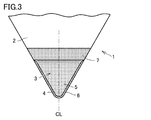
- FIG. 3 is a plan view of the cutting edge portion of FIG.
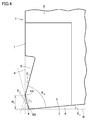
- FIG. 4 is a sectional view taken along the angle bisector CL of the nose R of FIG.
- FIG. 5 is a schematic cross-sectional view for explaining constituent blade edges formed during cutting.
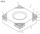
- FIG. 6 is a perspective view showing another example of the cutting tool according to the present embodiment.
- FIG. 7 is a perspective view showing another example of the cutting tool according to the present embodiment.
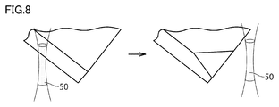
- FIG. 8 is a schematic diagram illustrating pulse laser processing.
- FIG. 9 is a graph showing the relationship between the wedge angle and the cutting length.
- FIG. 9 is a graph showing the relationship between the wedge angle and the cutting length.
- FIG. 10 is a graph showing the relationship between the sum of the rake angle and the chamfer angle and the cutting length.
- FIG. 11 is a graph showing the relationship between cutting speed and cutting length.
- FIG. 12 is a graph showing the relationship between the feed amount and the cutting length.
- a cubic boron nitride sintered body (cBN sintered body) having excellent high-temperature hardness is used for the cutting edge portion.
- Cutting tools (cBN sintered compact cutting tools) are known (for example, JP-A-2005-208807 (Patent Document 1) and International Publication No. 2014/181594 (Patent Document 2)).
- cBN sintered compact cutting tools are known (for example, JP-A-2005-208807 (Patent Document 1) and International Publication No. 2014/181594 (Patent Document 2)).
- a cBN sintered body cutting tool In order to improve the processing efficiency of difficult-to-cut materials using such a cBN sintered body cutting tool, it is being studied to perform processing at a cutting speed of 200 m/min or more. Further, in order to achieve higher cutting efficiency such as improving the cutting speed and lowering the cutting resistance, it has been considered to make the wedge angle sharp in the cBN sintered body cutting tool.
- the cBN sintered body has higher hardness than cemented carbide, it has low toughness. Therefore, if the wedge angle is sharpened in the cBN sintered body cutting tool, when the heat resistant alloy such as the nickel-base heat resistant alloy is cut, the boundary wear damage becomes large and the cutting edge tends to be damaged.
- an object of the present invention is to provide a cutting tool having excellent wear resistance in cutting of a nickel-base heat-resistant alloy, a method for manufacturing the cutting tool, and a method of processing a nickel-base heat-resistant alloy.
- a cutting tool includes A cubic boron nitride and a cutting tool including a cubic boron nitride sintered body consisting of a binder phase, A rake face, a flank face, and a chamfer face connecting the rake face and the flank face,
- the wedge angle formed by the rake face and the flank face is 60° or more and 70° or less
- the sum of the rake angle on the rake face and the chamfer angle on the chamfer face is 20° or more and 40° or less
- the chamfer length on the chamfer surface is 20 ⁇ m or more and 90 ⁇ m or less
- the cubic boron nitride has an average particle size of 0.5 ⁇ m or more and 2 ⁇ m or less
- the volume ratio of the cubic boron nitride is 45% by volume or more and 99% by volume or less
- the above cutting tool becomes a cutting tool having excellent wear resistance in the cutting of nickel-base heat-resistant alloy.
- the rake angle is 10° or more and 20° or less.
- the chamfer angle is 10° or more and 20° or less.
- the clearance angle on the clearance surface is 0° or more and 10° or less.
- the chamfer length is 20 ⁇ m or more and 50 ⁇ m or less.
- a method for manufacturing a cutting tool according to the present disclosure A method of manufacturing the cutting tool, including a step of forming the chamfer surface by pulse laser processing.
- a processing method of a nickel-base heat-resistant alloy according to the present disclosure A method for processing a nickel-base heat-resistant alloy using the above cutting tool, comprising a peripheral speed of 250 m/min or more and 400 m/min or less, a cutting amount of 1 mm or more and 2 mm or less, and a feed amount of 0.07 mm/rev or more and 0.1 mm/rev or less.
- the process includes wet processing under the conditions.
- this embodiment is not limited to this.
- the notation in the form of "AZ" means the upper and lower limits of the range (that is, A or more and Z or less), and when A has no unit, and only Z has a unit, A And the unit of Z are the same.
- a compound is represented by a chemical formula in which the composition ratio of constituent elements is not limited, such as “TiN”, the chemical formula is represented by any conventionally known composition ratio (element ratio). Shall be included.
- the above chemical formula includes not only the stoichiometric composition but also the non-stoichiometric composition.
- the chemical formula “TiN” includes not only the stoichiometric composition “Ti 1 N 1 ”, but also a non-stoichiometric composition such as “Ti 1 N 0.8 ”. This also applies to the description of compounds other than "TiN”.
- the wedge angle formed by the rake face and the flank face is 60 to 70°
- the sum of the rake angle on the rake face and the chamfer angle on the chamfer face is 20 to 40°
- the chamfer length on the chamfer surface is 20 to 90 ⁇ m
- the cubic boron nitride has an average particle size of 0.5 to 2 ⁇ m
- the volume ratio of the cubic boron nitride is 45 to 99% by volume based on the whole cubic boron nitride sintered body
- the bonded phase is at least one element selected from Group 4 elements, Group 5 elements and Group 6 elements of the periodic table of elements, and C (carbon), N (nitrogen
- FIG. 1 is a perspective view showing an example of a cutting tool according to this embodiment.
- FIG. 2 is an enlarged view of a cutting edge portion of the cutting tool of FIG.
- the cutting tool 1 according to the present embodiment has a rake face 5, a flank face 6, and a chamfer face 4 connecting the rake face 5 and the flank face 6. .
- the cutting tool 1 according to the present embodiment has the rake face 5, the flank face 6, and the chamfer face 4 in the cutting edge portion 3.
- the cutting tool 1 may be in the form of a throw-away tip that includes a cutting edge tip (portion hatched with fine dots in FIGS. 1 and 2) and a base metal 2 that holds the cutting edge tip, or the cutting edge tip. It may be its own shape. However, the shape of the cutting tool 1 is not limited to the shape described above.
- FIG. 3 is a plan view of the cutting edge portion of FIG.
- FIG. 4 is a sectional view taken along the angle bisector CL of the nose R of FIG.
- the cross-sectional view of FIG. 4 is a cross section cut perpendicular to a boundary line AA between the rake face 5 and the chamfer surface 4 and a boundary line BB between the flank face 6 and the chamfer surface 4 described later. It is a figure.
- the cross-sectional view of FIG. 4 can also be understood as a cross-sectional view cut along the angle bisector CL of the nose R and perpendicular to the rake face, the flank face and the chamfer face. .. In the cutting tools shown in FIGS.
- FIG. 4 has been described as a cross section of the nose R portion.
- the cutting tool according to the present disclosure is not limited to the embodiments shown in FIGS. 1 to 3, and if the cross section of a portion of the cutting tool involved in cutting has a shape as shown in FIG. It may have any configuration.
- the cutting tool has a wedge angle ⁇ w formed by the rake face and the flank (that is, an intersection angle at which a virtual plane including the rake face and a virtual plane including the flank intersect) of 60 to 70°. And more preferably 65 to 70°. By doing so, it becomes possible to suppress the cutting resistance.
- the sum of the wedge angle ⁇ w , the rake angle ⁇ R and the clearance angle ⁇ F described later is 90°.
- the sum of the rake angle on the rake face and the chamfer angle on the chamfer face is 20 to 40°, and more preferably 25 to 35°.
- the “rake angle” means an angle ⁇ R formed by the rake surface 5 and an imaginary plane A including the rake side main surface 7 as shown in FIG. 4.
- the virtual plane A can be grasped as a virtual plane orthogonal to the main surface of the work material, or can be grasped as a virtual plane perpendicular to the cutting direction. ..
- “Chamfer angle” means an angle ⁇ c formed by the chamfer surface 4 and the virtual plane A, as shown in FIG.
- the chamfer angle ⁇ c is preferably 10 to 20°, more preferably 15 to 20°.
- the constituent cutting edge described below tends to be stably generated.
- the chamfer length on the chamfer surface is 20 to 90 ⁇ m, preferably 20 to 50 ⁇ m.
- the “Chamfer length” means the distance L c between the boundary line AA between the rake surface 5 and the chamfer surface 4 and the boundary line BB between the flank surface 6 and the chamfer surface 4. To do.
- the chamfer width W c is preferably 20 to 90 ⁇ m.
- the chamfer width W c is a value obtained by (champfer length L c ) ⁇ cos (chamfer angle ⁇ c ).
- the chamfer width W c corresponds to the height when the chamfer surface 4 is projected on the virtual plane A (FIG. 4 ).
- the constituent cutting edge described below tends to be stably generated.
- the rake angle ⁇ R is preferably 10 to 20°, more preferably 15 to 20°.
- the clearance angle ⁇ F at the clearance surface is preferably 0 to 10°, more preferably 5 to 8°.
- the “clearance angle” means an angle ⁇ F formed by the clearance plane 6 and a virtual plane B orthogonal to the virtual plane A.
- the virtual plane B can be understood as a virtual plane including the main surface of the work material, or as a virtual plane parallel to the cutting direction.
- the shape of the cutting tool according to the present disclosure has been described above.
- the cutting tool has a wedge angle ⁇ w of 60 to 70°. Therefore, it is possible to cut the nickel-base heat-resistant alloy with a rake angle ⁇ R of 10 to 20°.
- the rake angle in the above range is common in cutting tools made of cemented carbide, high-speed steel or the like having high toughness.
- setting the rake angle to 10 to 20° has not been conventionally performed. The inventors believe that there are two reasons for this.
- the first reason is that although the cBN sintered body has high hardness, it has low toughness, so it is important to increase the fracture resistance of the cBN sintered body cutting tool for cutting nickel-base heat resistant alloys. It was thought that. From such a viewpoint, it has been considered preferable to design the rake angle of the cBN sintered body cutting tool to be less than 10°.
- the second reason is that when the rake angle is designed to be 10° or more, the cutting edge temperature decreases due to improved sharpness (that is, reduced cutting resistance).
- a method is adopted in which the temperature of the cutting edge is raised and the heat-resistant alloy, which is a work material, is softened by the generated cutting heat. It has been theoretically considered that even if the rake angle is designed to be 10° or more, the desired cutting edge temperature can be achieved by increasing the cutting speed.
- the cutting tool manufactured by the grinding process using the conventional diamond grindstone there is a microstructure destruction in the cutting edge as described later, so that the cutting edge becomes defective when the cutting speed is increased. It has not been put to practical use. From such a point of view, it has been considered that designing the rake angle to be 10° or more would make it difficult to cut the heat-resistant alloy and prevent the cutting edge from being damaged.
- the cutting tool according to the present disclosure has a chamfered surface formed by pulsed laser processing as described below, and thus microscopic tissue destruction occurring at the cutting edge is suppressed.
- the nickel-base heat-resistant alloy can be cut with high cutting efficiency (for example, high cutting speed). That is, in the cutting tool according to the present embodiment, the above-mentioned shape and the specific cBN sintered body described later are combined to form the constituent cutting edge steadily, so that the cutting resistance of the nickel-base heat-resistant alloy is reduced in wear resistance.
- a cutting tool with excellent fracture resistance can be provided.
- the cutting tool includes a cubic boron nitride sintered body including cubic boron nitride and a binder phase.
- the thermal conductivity of the cubic boron nitride sintered body (hereinafter sometimes referred to as “cBN sintered body”) is 20 to 70 W/m ⁇ K.
- the thermal conductivity for example, the thermal diffusivity of the cubic boron nitride sintered body obtained by measuring by the laser flash method, and the specific heat and density of the cubic boron nitride sintered body calculated by another method Can be calculated based on
- the average particle size of the cubic boron nitride (hereinafter sometimes referred to as “cBN”) is 0.5 to 2 ⁇ m. By doing so, a cBN sintered body having the above-described predetermined thermal conductivity can be obtained.
- the average grain size of cubic boron nitride is calculated as follows. First, an arbitrary position of the cutting tool according to the present embodiment is cut, and a sample including the cut surface is manufactured. Then, the cut surface of the cutting tool is observed using a SEM (scanning electron microscope) to obtain a backscattered electron image. The backscattered electron image obtained is analyzed using image analysis software, and the equivalent circle diameter of the corresponding region of cubic boron nitride is calculated. The average value is calculated from the calculated equivalent circle diameters. The obtained average value is defined as “average particle size of cubic boron nitride”.
- the volume ratio of the cubic boron nitride is 45 to 99% by volume, preferably 60 to 99% by volume, based on the whole of the cubic boron nitride sintered body.
- the volume ratio (volume %) of cubic boron nitride in the cubic boron nitride sintered body is obtained as follows. First, a sample including the cut surface of the above cutting tool is prepared and a backscattered electron image is obtained. Next, for the backscattered electron image, the region of cubic boron nitride is specified using the image analysis software described above. After that, the area ratio of the region of the cubic boron nitride is obtained, and this area ratio is treated as the volume ratio of the cubic boron nitride.
- the bonding phase includes at least one element selected from Group 4, Group 5 and Group 6 elements of the periodic table of elements and at least one element selected from C, N, B and O. .. More specifically, the binder phase is a nitride such as TiN, Si 3 N 4 or AlN, a carbide such as TiC or WC, a boride such as TiB 2 or AlB 2 or an oxide such as Al 2 O 3. Alternatively, it is made of TiCN, AlON, SiAlON, SiTiAlON, or other solid solution thereof, and particularly preferably contains any one of Al 2 O 3 , AlON, and SiAlON. Examples of the Group 4 element include Ti (titanium), Zr (zirconium), and Hf (hafnium).
- Examples of the Group 5 element include V (vanadium), Nb (niobium), and Ta (tantalum).
- Examples of the Group 6 element include Cr (chromium), Mo (molybdenum), and W (tungsten).
- TEM-EDX energy dispersive X-ray spectroscopy
- the cubic boron nitride sintered body may contain inevitable impurities as long as the effect of the present disclosure is not impaired.
- the unavoidable impurities are generic names of elements and compounds that may be contained in a trace amount in the raw material of the cubic boron nitride sintered body or in the production thereof.
- the content (volume %) of each element and compound contained as unavoidable impurities is 0 volume% or more and 5 volume% or less, respectively, and the sum of these (that is, the content of trace impurities) is 0 volume% or more and 5 volume% or less. Is. Therefore, inevitable impurities may or may not be contained in the cubic boron nitride sintered body.
- Examples of unavoidable impurities include Li, Mg, Ca, Sr, Ba, Be, Si, Ga, La, Zr, V, Nb, Ta, Hf, Fe and Cu.
- the cutting tool according to the present disclosure has been described.
- the cutting tool according to the present disclosure by combining the shape of the specific cutting tool described above and a specific cubic boron nitride sintered body, in the cutting process of the nickel-base heat-resistant alloy, wear resistance, chipping resistance It has been improved and a long life which has never been achieved is achieved.
- the detailed mechanism that exerts such an excellent effect is unknown, the present inventors believe that there are two factors described below.
- the first reason is that the wear of the rake face (crater wear) and the wear of the flank face (flank wear) at the cutting edge of the cutting tool progress in parallel, which balances the wear progress rates. Therefore, the apparent speed at which the width of crater wear and the width of flank wear increase is decreased.
- the abrasive wear of the cutting tool progresses at a high speed, but due to the progress of wear on the flank, the position of the cutting edge recedes and the flank wear width increases. At the same time, since the crater wear also progresses from the rake face, the flank wear width is apparently shortened.
- the width of crater wear on the rake face also increases with the progress of wear on the rake face, but the width of crater wear is apparently shortened due to the retreat of the cutting edge due to flank wear.
- the wear of the cutting edge progresses while the width of the crater wear that the cutting edge contacts with the chips and the width of the flank wear that contacts the machining surface are smaller than those of conventional tools, reducing the cutting edge friction heat and cutting resistance. It is thought that it is connected to.
- the second reason is that the cutting tool has a chamfered surface having a predetermined angle and length.
- a force that causes chips to flow in the component direction of the tool feed changes the outflow direction of chips. ..
- This phenomenon is caused by the flow of the chips flowing out from the cutting edge (between the chips and the tool rake surface), and the constituent cutting edge (a part of the work material welded on the chamfer surface) does not stick and is fluidized.
- FIG. 5 is a schematic cross-sectional view for explaining constituent blade edges formed during cutting.
- the constituent cutting edge normally undergoes a process in which a part of the work material adheres to the cutting edge of the cutting tool and grows and falls off.
- the constituent cutting edge 8 formed in the cutting tool 1 according to the present disclosure the generation and flow of the specific shape by a part of the work material are continued steadily and stably instead of the above-described process. Therefore, the constituent cutting edge 8 is provided between the chamfer surface 4 of the cutting tool 1 and the chips of the work material 9 and interposed therebetween to protect the cutting edge portion 3 of the cutting tool 1 (for example, , FIG. 5).
- the present inventors believe that such a phenomenon of stable generation of the cutting edge does not occur in a cemented carbide tool, a cermet tool, a ceramics tool, etc. having the same shape, and is a phenomenon peculiar to a cBN sintered body. ing.
- the cutting tool 1 may have a shape having cutting edge portions 3 at four corners as shown in FIG. Further, as shown in FIG. 7, a predetermined side of the cutting tool 1 may have a shape that constitutes the cutting edge portion 3.
- the cutting tool 1 is a throwaway tool including a cutting edge tip (portion hatched with fine dots in FIGS. 6 and 7) and a base metal 2 holding the cutting edge tip. It goes without saying that the shape of the tip may be the shape of the cutting edge tip itself.
- Manufacturing method of cutting tools The manufacturing method of the cutting tool according to the present disclosure, A method of manufacturing the cutting tool, including a step of forming the chamfer surface by pulse laser processing.
- the chamfer surface may be formed by pulse laser processing from the beginning, or after the chamfer surface is roughly processed by grinding with a diamond grindstone, the chamfer surface is processed by pulse laser processing. It may be formed by finishing the surface.
- FIG. 8 is a schematic diagram illustrating pulse laser processing.
- a region shown by a dot in FIG. 8 is a laser processing region 50, and for example, a plane of about 0.5 mm can be processed by uniaxial scanning.
- the device for generating the pulse laser is not particularly limited, but may be, for example, a device having the configuration disclosed in Japanese Patent Laid-Open No. 2016-159318 (Patent Document 3).
- Patent Document 3 Japanese Patent Laid-Open No. 2016-159318
- Examples of the commercially available device include Impact-3C manufactured by Xiton Co., Ltd.
- the conditions for the pulse laser processing are as follows, for example. Conditions for pulsed laser processing Laser wavelength: 355-1064nm Laser power: 2.5-10W Pulse width: 700fs-5ns Beam diameter: 20-40 ⁇ m Scan speed: 20-40mm/s Incident angle: 80-88.5° Cutting depth: 1-10 ⁇ m
- a cutting tool having a cBN sintered body as a cutting edge has a cutting edge portion formed by grinding with a diamond grindstone.
- the cBN sintered body is a brittle material with high hardness
- the cutting edge (cutting edge portion) generated by the conventional grinding process causes microstructural destruction around the ridge line of the cutting edge portion due to the stress applied by the grinding resistance. It was formed with it.
- a slight chipping occurs in the ridgeline portion of the cutting edge portion, and a microstructure defect accompanied by damage such as a minute crack occurs inside the cBN sintered body.
- the present inventors believe that these microstructure defects may cause damage to the cutting edge portion during cutting and cause unstable tool life. Especially, it has a great influence on a cutting tool having a small wedge angle and a large rake angle and a clearance angle designed. Therefore, in general, even if the rake angle is increased to manufacture a cutting tool with better sharpness, the strength of the cutting edge portion tends to decrease, and conversely the tool life tends to decrease. Therefore, the design value of the rake angle must be set to an upper limit (for example, less than 10°).
- pulse laser processing is used to form a chamfer surface, thereby realizing processing in which a microstructure defect is suppressed in the cBN sintered body at the cutting edge.
- the rake angle and the clearance angle of the cutting edge of the cutting tool can be designed to be large angles that cannot be conventionally assumed.
- the cutting tool manufactured by the above manufacturing method can achieve a long life under severe processing conditions such as high-speed processing of a nickel-base heat-resistant alloy.
- the processing method of the nickel-base heat-resistant alloy according to the present disclosure A method for processing a nickel-base heat-resistant alloy using the above cutting tool, which comprises a wet processing step under conditions of a peripheral speed of 250 to 400 m/min, a cutting amount of 1 to 2 mm, and a feed amount of 0.07 to 0.1 mm/rev. Including.
- the cutting edge portion is formed of a cBN sintered body having a low thermal conductivity as described above, and a specific wedge angle, chamfer angle, chamfer length, etc. are imparted.
- crater wear wear on the rake face
- flank wear wear on the flank face
- the life was improved as compared with the conventional cutting tool.
- the wear of the cutting edge portion progresses and the cutting resistance increases.
- the peripheral speed is 250 to 400 m/min (preferably 250 to 300 m/min)
- the cutting amount is 1 to 2 mm (preferably 1 to 1.7 mm)
- the feed amount is 0.07 to 0.1 mm/rev (preferably , 0.07 to 0.08 mm/rev)
- a cubic boron nitride and a cutting tool including a cubic boron nitride sintered body consisting of a binder phase, A rake face, a flank face, and a chamfer face connecting the rake face and the flank face,
- the wedge angle formed by the rake face and the flank face is 60 to 70°
- the sum of the rake angle on the rake face and the chamfer angle on the chamfer face is 20 to 40°
- the chamfer length on the chamfer surface is 20 to 90 ⁇ m
- the cubic boron nitride has an average particle size of 0.5 to 2 ⁇ m
- the cubic boron nitride has a volume ratio of 45 to 70% by volume based on the whole cubic boron nitride sintered body.
- the bonding phase includes at least one element selected from Group 4 elements, Group 5 elements and Group 6 elements of the periodic table of elements and at least one element selected from C, N, B and O.
- the cutting tool wherein the cubic boron nitride sintered body has a thermal conductivity of 20 to 70 W/m ⁇ K.
- Appendix 2 The cutting tool according to Appendix 1, wherein the rake angle is 10 to 20°.
- Appendix 3 The cutting tool according to Appendix 1 or Appendix 2, wherein the chamfer angle is 10 to 20°.
- Appendix 4 The cutting tool according to any one of appendixes 1 to 3, wherein the clearance angle on the flank is 0 to 10°. (Appendix 5) 5.
- Appendix 6 The method for manufacturing a cutting tool according to any one of appendixes 1 to 5, including a step of forming the chamfer surface by pulse laser processing.
- Appendix 7) A method for processing a nickel-base heat-resistant alloy using the cutting tool according to any one of appendixes 1 to 5, wherein a peripheral speed is 250 to 400 m/min, a cutting amount is 1 to 2 mm, and a feed amount is 0.07 to 0.1 mm.
- Experiment 1 ⁇ Preparation of cutting tools>> A cutting tool was produced using materials A to F described later and its cutting performance was evaluated.
- the cutting tool has the shape of a cutting edge tip shown by hatching of fine dots in FIG. Further, the rake angle, the clearance angle, the wedge angle, the chamfer angle and the chamfer length in the cutting tool were made to have variations, and each cutting tool was manufactured.
- the chamfer surface of each cutting tool was processed by pulse laser processing under the following conditions. Conditions for pulsed laser processing Laser wavelength: 355-1064nm Laser power: 2.5-10W Pulse width: 700fs-5ns Beam diameter: 20-40 ⁇ m Scan speed: 20-40mm/s Incident angle: 80-88.5° Cutting depth: 1-10 ⁇ m
- Table 1 shows the composition and thermal conductivity of cBN sintered bodies corresponding to materials A to D, and the average particle size of cBN.
- TiC ceramics material E, thermal conductivity 15 to 18 W/m ⁇ K
- WC material F, thermal conductivity 80 to 100 W/m ⁇ K
- ⁇ Cutting test ⁇ ⁇ Cutting test 1: roughing test> The cutting tool produced as described above is fixed to the base metal, the nickel-base heat-resistant alloy is roughly machined under the following cutting conditions, and the cutting distance until the flank wear of the cutting tool reaches 0.3 mm is measured. did. The longer the cutting distance, the more excellent the wear resistance can be evaluated as a cutting tool.
- Table 2 shows the rake angle, clearance angle, wedge angle, chamfer angle, and chamfer length of the cutting tools manufactured this time that had the longest cutting length in Cutting Test 1 (the cutting tools of Sample Nos. 1 to 10). Show. In addition, the sample No. Table 3 shows the cutting distance and the chip discharge efficiency of the cutting tools of 1 to 10.
- Sample No. for cutting test 1 The cutting tools 1 to 10 (Examples) had a cutting distance of 2500 m or more in rough machining of Inconel (registered trademark) 718, which is a nickel-based heat-resistant alloy, and a chip discharge efficiency of 9 to 36 cc/min.
- the cutting tools 1 to 5 and 7 to 10 were manufactured from the cBN sintered body of the material C.
- Sample No. The cutting tool of No. 6 was manufactured from the cBN sintered body of the material B.
- Experiment 2 ⁇ Examination of correlation between cutting tool shape and cutting length>> Correlation between the shape of the cutting tool (particularly, the wedge angle, and the sum of the rake angle and the chamfer angle) and the cutting length (cutting distance) using the cutting tool manufactured in ⁇ Preparation of cutting tool>> in Experiment 1. It was investigated. The cutting test at this time was performed under the same conditions as the cutting test 1 described above. The results are shown in FIGS. 9 and 10. A cutting tool having a cutting length of 2000 m or more was evaluated as a cutting tool having a long life. From the results of FIG. 9, it was suggested that the cutting tool having a wedge angle of 65 to 70° has a long cutting length and a particularly long life (a broken line region in FIG. 9). From the results of FIG. 10, it was suggested that the cutting tool having a sum of the rake angle and the chamfer angle of 25 to 35° has a long cutting length and a particularly long life (a broken line region in FIG. 10).
Landscapes
- Engineering & Computer Science (AREA)
- Chemical & Material Sciences (AREA)
- Mechanical Engineering (AREA)
- Ceramic Engineering (AREA)
- Crystallography & Structural Chemistry (AREA)
- Plasma & Fusion (AREA)
- Optics & Photonics (AREA)
- Manufacturing & Machinery (AREA)
- Physics & Mathematics (AREA)
- Materials Engineering (AREA)
- Structural Engineering (AREA)
- Organic Chemistry (AREA)
- Cutting Tools, Boring Holders, And Turrets (AREA)
Abstract
L'invention concerne un outil de coupe qui comprend un corps fritté en nitrure de bore cubique constitué de nitrure de bore cubique et une phase liée, l'outil de coupe ayant une face de raclette, une face de dépouille et une face de chanfrein joignant la face de raclette et la face de dépouille ; un angle de coin formé par la face de raclette et la face de dépouille étant de 60° à 70° ; la somme d'un angle de raclette au niveau de la face de raclette et d'un angle de chanfrein au niveau de la face de chanfrein étant de 20° à 40° ; une longueur de chanfrein dans la face de chanfrein étant de 20 à 90 µm ; la taille moyenne des particules du nitrure de bore cubique étant de 0,5 à 2 µm ; le rapport volumique du nitrure de bore cubique étant de 45 à 70 % en volume par rapport à la totalité du corps fritté en nitrure de bore cubique ; la phase liée contenant au moins un élément parmi les éléments du groupe 4, les éléments du groupe 5 et les éléments du groupe 6 du tableau périodique des éléments, et au moins un élément parmi du carbone, de l'azote, du bore et de l'oxygène ; et la conductivité thermique du corps fritté en nitrure de bore cubique étant de 20 à 70 W/m⋅K.
Applications Claiming Priority (2)
| Application Number | Priority Date | Filing Date | Title |
|---|---|---|---|
| JP2019036062 | 2019-02-28 | ||
| JP2019-036062 | 2019-02-28 |
Publications (1)
| Publication Number | Publication Date |
|---|---|
| WO2020174877A1 true WO2020174877A1 (fr) | 2020-09-03 |
Family
ID=72239548
Family Applications (1)
| Application Number | Title | Priority Date | Filing Date |
|---|---|---|---|
| PCT/JP2020/000051 Ceased WO2020174877A1 (fr) | 2019-02-28 | 2020-01-06 | Outil de coupe, son procédé de production et procédé d'usinage d'alliage résistant à la chaleur à base de nickel |
Country Status (1)
| Country | Link |
|---|---|
| WO (1) | WO2020174877A1 (fr) |
Cited By (2)
| Publication number | Priority date | Publication date | Assignee | Title |
|---|---|---|---|---|
| JP7098211B1 (ja) * | 2021-02-26 | 2022-07-11 | 国立大学法人 名古屋工業大学 | レーザ加工装置、厚さ検出方法および厚さ検出装置 |
| CN115156564A (zh) * | 2022-07-27 | 2022-10-11 | 哈尔滨工业大学(深圳) | 一种镍基粉末高温合金涡轮盘表面完整性的车削加工方法 |
Citations (8)
| Publication number | Priority date | Publication date | Assignee | Title |
|---|---|---|---|---|
| US3395434A (en) * | 1966-06-01 | 1968-08-06 | Sandvikens Jernverks Ab | Cutting insert for chip cutting machining |
| JPH1043903A (ja) * | 1996-07-30 | 1998-02-17 | Sumitomo Electric Ind Ltd | 結晶材料の超精密切削加工方法 |
| JP2003175408A (ja) * | 1999-11-25 | 2003-06-24 | Sumitomo Electric Ind Ltd | 多結晶硬質焼結体スローアウェイチップ |
| JP2010125566A (ja) * | 2008-11-28 | 2010-06-10 | Sumitomo Electric Ind Ltd | 切削チップと切削工具と難削材の切削方法 |
| WO2014126178A1 (fr) * | 2013-02-13 | 2014-08-21 | 京セラ株式会社 | Outil de coupe |
| WO2016043127A1 (fr) * | 2014-09-16 | 2016-03-24 | 住友電気工業株式会社 | Plaquette de coupe et son procédé de fabrication |
| JP2016190317A (ja) * | 2016-05-19 | 2016-11-10 | 住友電工ハードメタル株式会社 | cBN切削工具 |
| WO2018123133A1 (fr) * | 2016-12-26 | 2018-07-05 | 住友電工ハードメタル株式会社 | Outil de coupe et son procédé de fabrication |
-
2020
- 2020-01-06 WO PCT/JP2020/000051 patent/WO2020174877A1/fr not_active Ceased
Patent Citations (8)
| Publication number | Priority date | Publication date | Assignee | Title |
|---|---|---|---|---|
| US3395434A (en) * | 1966-06-01 | 1968-08-06 | Sandvikens Jernverks Ab | Cutting insert for chip cutting machining |
| JPH1043903A (ja) * | 1996-07-30 | 1998-02-17 | Sumitomo Electric Ind Ltd | 結晶材料の超精密切削加工方法 |
| JP2003175408A (ja) * | 1999-11-25 | 2003-06-24 | Sumitomo Electric Ind Ltd | 多結晶硬質焼結体スローアウェイチップ |
| JP2010125566A (ja) * | 2008-11-28 | 2010-06-10 | Sumitomo Electric Ind Ltd | 切削チップと切削工具と難削材の切削方法 |
| WO2014126178A1 (fr) * | 2013-02-13 | 2014-08-21 | 京セラ株式会社 | Outil de coupe |
| WO2016043127A1 (fr) * | 2014-09-16 | 2016-03-24 | 住友電気工業株式会社 | Plaquette de coupe et son procédé de fabrication |
| JP2016190317A (ja) * | 2016-05-19 | 2016-11-10 | 住友電工ハードメタル株式会社 | cBN切削工具 |
| WO2018123133A1 (fr) * | 2016-12-26 | 2018-07-05 | 住友電工ハードメタル株式会社 | Outil de coupe et son procédé de fabrication |
Cited By (2)
| Publication number | Priority date | Publication date | Assignee | Title |
|---|---|---|---|---|
| JP7098211B1 (ja) * | 2021-02-26 | 2022-07-11 | 国立大学法人 名古屋工業大学 | レーザ加工装置、厚さ検出方法および厚さ検出装置 |
| CN115156564A (zh) * | 2022-07-27 | 2022-10-11 | 哈尔滨工业大学(深圳) | 一种镍基粉末高温合金涡轮盘表面完整性的车削加工方法 |
Similar Documents
| Publication | Publication Date | Title |
|---|---|---|
| JP6459106B1 (ja) | 超硬合金及び切削工具 | |
| JP6206695B1 (ja) | 工具 | |
| US12318846B2 (en) | Diamond tool | |
| WO2020174877A1 (fr) | Outil de coupe, son procédé de production et procédé d'usinage d'alliage résistant à la chaleur à base de nickel | |
| CN114286731B (zh) | 金刚石切削工具及其制造方法 | |
| JP6912032B2 (ja) | 切削工具 | |
| CN116096517B (zh) | 立方晶氮化硼烧结体工具 | |
| JP4443177B2 (ja) | スローアウェイチップ | |
| JP6683887B2 (ja) | セラミックス焼結体、インサート、切削工具、及び摩擦攪拌接合用工具 | |
| US20180272433A1 (en) | Tool | |
| KR102897011B1 (ko) | 다이아몬드 절삭 공구 | |
| JP6834111B1 (ja) | 切削工具 | |
| KR20230043852A (ko) | 입방정 질화붕소 소결체 및 그것을 포함하는 절삭 공구 | |
| US12109629B1 (en) | Cutting tool | |
| JP2005231928A (ja) | サイアロン焼結体、サイアロン質工具、切削インサート、及び切削工具 | |
| JP2020157455A (ja) | ダイヤモンド被覆超硬合金製工具 | |
| JP7329323B2 (ja) | セラミックス焼結体、インサート、切削工具、及び摩擦攪拌接合用工具 | |
| JP2011167829A (ja) | チタン合金加工用切削工具 | |
| CN120018923A (zh) | 切削工具 |
Legal Events
| Date | Code | Title | Description |
|---|---|---|---|
| 121 | Ep: the epo has been informed by wipo that ep was designated in this application |
Ref document number: 20762418 Country of ref document: EP Kind code of ref document: A1 |
|
| NENP | Non-entry into the national phase |
Ref country code: DE |
|
| 122 | Ep: pct application non-entry in european phase |
Ref document number: 20762418 Country of ref document: EP Kind code of ref document: A1 |
|
| NENP | Non-entry into the national phase |
Ref country code: JP |