WO2020177157A1 - Système de détection pour articles de coagulation à indices multiples - Google Patents
Système de détection pour articles de coagulation à indices multiples Download PDFInfo
- Publication number
- WO2020177157A1 WO2020177157A1 PCT/CN2019/078980 CN2019078980W WO2020177157A1 WO 2020177157 A1 WO2020177157 A1 WO 2020177157A1 CN 2019078980 W CN2019078980 W CN 2019078980W WO 2020177157 A1 WO2020177157 A1 WO 2020177157A1
- Authority
- WO
- WIPO (PCT)
- Prior art keywords
- detection
- chip
- module
- main board
- index
- Prior art date
- Legal status (The legal status is an assumption and is not a legal conclusion. Google has not performed a legal analysis and makes no representation as to the accuracy of the status listed.)
- Ceased
Links
Images




Classifications
-
- G—PHYSICS
- G01—MEASURING; TESTING
- G01N—INVESTIGATING OR ANALYSING MATERIALS BY DETERMINING THEIR CHEMICAL OR PHYSICAL PROPERTIES
- G01N33/00—Investigating or analysing materials by specific methods not covered by groups G01N1/00 - G01N31/00
- G01N33/48—Biological material, e.g. blood, urine; Haemocytometers
- G01N33/483—Physical analysis of biological material
- G01N33/487—Physical analysis of biological material of liquid biological material
- G01N33/49—Blood
- G01N33/4905—Determining clotting time of blood
-
- B—PERFORMING OPERATIONS; TRANSPORTING
- B01—PHYSICAL OR CHEMICAL PROCESSES OR APPARATUS IN GENERAL
- B01L—CHEMICAL OR PHYSICAL LABORATORY APPARATUS FOR GENERAL USE
- B01L3/00—Containers or dishes for laboratory use, e.g. laboratory glassware; Droppers
- B01L3/50—Containers for the purpose of retaining a material to be analysed, e.g. test tubes
- B01L3/502—Containers for the purpose of retaining a material to be analysed, e.g. test tubes with fluid transport, e.g. in multi-compartment structures
- B01L3/5027—Containers for the purpose of retaining a material to be analysed, e.g. test tubes with fluid transport, e.g. in multi-compartment structures by integrated microfluidic structures, i.e. dimensions of channels and chambers are such that surface tension forces are important, e.g. lab-on-a-chip
- B01L3/502715—Containers for the purpose of retaining a material to be analysed, e.g. test tubes with fluid transport, e.g. in multi-compartment structures by integrated microfluidic structures, i.e. dimensions of channels and chambers are such that surface tension forces are important, e.g. lab-on-a-chip characterised by interfacing components, e.g. fluidic, electrical, optical or mechanical interfaces
-
- B—PERFORMING OPERATIONS; TRANSPORTING
- B01—PHYSICAL OR CHEMICAL PROCESSES OR APPARATUS IN GENERAL
- B01L—CHEMICAL OR PHYSICAL LABORATORY APPARATUS FOR GENERAL USE
- B01L7/00—Heating or cooling apparatus; Heat insulating devices
-
- G—PHYSICS
- G01—MEASURING; TESTING
- G01N—INVESTIGATING OR ANALYSING MATERIALS BY DETERMINING THEIR CHEMICAL OR PHYSICAL PROPERTIES
- G01N33/00—Investigating or analysing materials by specific methods not covered by groups G01N1/00 - G01N31/00
- G01N33/48—Biological material, e.g. blood, urine; Haemocytometers
- G01N33/50—Chemical analysis of biological material, e.g. blood, urine; Testing involving biospecific ligand binding methods; Immunological testing
- G01N33/86—Chemical analysis of biological material, e.g. blood, urine; Testing involving biospecific ligand binding methods; Immunological testing involving blood coagulating time or factors, or their receptors
-
- B—PERFORMING OPERATIONS; TRANSPORTING
- B01—PHYSICAL OR CHEMICAL PROCESSES OR APPARATUS IN GENERAL
- B01L—CHEMICAL OR PHYSICAL LABORATORY APPARATUS FOR GENERAL USE
- B01L2200/00—Solutions for specific problems relating to chemical or physical laboratory apparatus
- B01L2200/08—Ergonomic or safety aspects of handling devices
- B01L2200/087—Ergonomic aspects
-
- B—PERFORMING OPERATIONS; TRANSPORTING
- B01—PHYSICAL OR CHEMICAL PROCESSES OR APPARATUS IN GENERAL
- B01L—CHEMICAL OR PHYSICAL LABORATORY APPARATUS FOR GENERAL USE
- B01L2300/00—Additional constructional details
- B01L2300/02—Identification, exchange or storage of information
- B01L2300/023—Sending and receiving of information, e.g. using Bluetooth®
-
- B—PERFORMING OPERATIONS; TRANSPORTING
- B01—PHYSICAL OR CHEMICAL PROCESSES OR APPARATUS IN GENERAL
- B01L—CHEMICAL OR PHYSICAL LABORATORY APPARATUS FOR GENERAL USE
- B01L2300/00—Additional constructional details
- B01L2300/06—Auxiliary integrated devices, integrated components
- B01L2300/0627—Sensor or part of a sensor is integrated
- B01L2300/0663—Whole sensors
-
- B—PERFORMING OPERATIONS; TRANSPORTING
- B01—PHYSICAL OR CHEMICAL PROCESSES OR APPARATUS IN GENERAL
- B01L—CHEMICAL OR PHYSICAL LABORATORY APPARATUS FOR GENERAL USE
- B01L2300/00—Additional constructional details
- B01L2300/08—Geometry, shape and general structure
- B01L2300/0809—Geometry, shape and general structure rectangular shaped
- B01L2300/0816—Cards, e.g. flat sample carriers usually with flow in two horizontal directions
-
- B—PERFORMING OPERATIONS; TRANSPORTING
- B01—PHYSICAL OR CHEMICAL PROCESSES OR APPARATUS IN GENERAL
- B01L—CHEMICAL OR PHYSICAL LABORATORY APPARATUS FOR GENERAL USE
- B01L2300/00—Additional constructional details
- B01L2300/18—Means for temperature control
Definitions
- the invention relates to the technical field of rapid detection of in vitro diagnostic equipment, in particular to a multi-index coagulation item detection system.
- the current coagulation analyzers on the market are mainly based on two methods: magnetic bead method and optical method.
- the magnetic bead method is based on the principle of using magnetic beads to swing and cut magnetic lines of force to generate electrical signals.
- the freezing point is determined by monitoring the swing amplitude of the magnetic beads.
- the attenuation of the magnetic bead swing is 50%, the freezing point is considered to be reached.
- This method is costly and requires high equipment manufacturing technology; the optical method determines the freezing point by optically analyzing the changes in turbidity during blood coagulation.
- the optical method has low cost and high precision, and the current new coagulation analyzer generally adopts the optical method.
- the above two detection methods are not intuitive enough, and the detection equipment is relatively complicated, the detection equipment is expensive, and the detection cost is also high. At the same time, the accuracy of the monitoring is often not satisfactory due to equipment or environmental factors.
- the portable blood coagulation test card includes: a bottom layer printed with detection electrodes, a middle layer through which a blood sample flows, and an upper layer through which the blood sample siphons.
- the upper layer, the middle layer and the bottom layer are arranged in order by pasting; the upper layer is provided with a sample application area for adding blood samples; the middle layer is provided with at least two test channels, one end of the test channel is connected to the sample application area, and the other One end is provided with a test area; one of the test channels is a delay channel, and there is an obstruction in the middle of the delay channel.
- the end of the test area is provided with air holes communicating with the upper layer; the inner side wall of the bottom layer is provided with an electrode conduction area connected to the test area; the end of the electrode conduction area is inserted into the test host for testing.
- the portable blood coagulation test card cannot realize the simultaneous detection of 5 indications of blood coagulation, the detection time is long, and the sample needs to be pre-processed.
- Chinese patent document discloses a hand-held blood analyzer, including a blood analyzer, a power switch, a display screen and a handle holder.
- the panel of the blood analyzer is provided with the display screen, so
- the power switch is provided below the display screen, one side of the power switch is provided with an LED lamp, one side of the LED lamp is provided with a detection window, and a detection area door is installed at the detection window.
- a handle is installed on the zone door, a sample placement slot is arranged at the bottom of the detection window, a detection head and an infrared sensor are arranged above the detection window, a handle is installed directly above the blood analyzer, and the lifting
- the hand is fixed on the blood analyzer through the handle fixing seat, and a main control circuit board is arranged inside the blood analyzer, and a photoelectric sensor, a filter, and a signal receiver are arranged under the main control circuit board.
- a processor and a signal transmitter one side of the signal transmitter is provided with a built-in WIFI, a battery is provided under the photoelectric sensor, and a charging line interface is provided on one side of the battery.
- the hand-held blood analyzer device has a large volume, a complicated structure, and a high detection cost.
- the invention provides a multi-index coagulation item detection system that can be detected immediately and can be operated without professionals, has high sensitivity, convenient operation, and constant heating temperature.
- the multi-index coagulation item detection system includes a housing, a detection heating module, a battery module, a touch screen and a main board
- the housing includes an upper housing and a lower housing
- the outer shell is formed by the upper shell and the lower shell butting to form a closed space
- the main board is arranged between the upper shell and the lower shell and is arranged in the closed space
- the touch display screen is arranged On the upper surface of the upper shell, the touch display screen is connected with the main board
- the detection heating module is arranged in the enclosed space and at the front end of the lower shell and connected with the main board
- the bottom of the end of the lower shell is provided with a battery module and the battery module is connected with the main board
- the front end of the shell is provided with a detection inlet for inserting a test card.
- the multi-index coagulation item detection system detects the signal that the sample enters the reaction chamber, and uses the AC impedance method to monitor the signal, applies AC voltage, and heats The film is heated to keep the temperature at 37 degrees.
- the detection heating module of the multi-index coagulation item detection system collects the signal changes, and the operation amplifier; after the reaction, the multi-index coagulation item is detected According to all the received signals, the system fits a complete response curve, and uses mathematical algorithms to calculate the signal point. This point is the detection result.
- the multi-index coagulation item detection system can detect instantaneously, and it can be operated without professionals. It has high sensitivity and operation. Convenient, reliable and widely applicable.
- the touch screen is fixed on the upper shell by screws
- the main board is embedded between the upper shell and the lower shell and is fixed on the lower shell by screws
- the detection heating module is fixed on the bottom of the lower shell by screws
- the shell and the lower shell are sealed but connected by screws to form a closed space.
- a code scanning module is further provided at the front end of the lower shell, and the code scanning module is connected to the main board. Put the test card into the multi-index coagulation item detection system to scan the code through the code scanning module before the test, identify the sample information and store it.
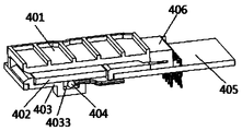
- the detection heating module includes a card slot, a heating plate, a heating plate card slot, a temperature sensor, a PCB board and a test card connector, and the test card connector is arranged on the PCB board, so
- the test card connector is connected to the main board through a circuit connector;
- the heating plate is used for constant-temperature heating and is installed in the heating plate slot, and the heating plate slot is installed on the PCB board and located in the test One side of the card connector;
- the temperature sensor one is arranged under the heating plate and is arranged in the heating plate slot;
- the card slot is installed on the upper surface of the heating plate and is connected to the heating plate in turn
- the chip card slot is engaged with the PCB board.
- This structure makes the connection of the test card and the detection heating module more convenient, and also makes the detection result of the detection heating module more accurate; the temperature sensor is used to monitor the temperature of the heating plate, and then the heating of the heating plate is controlled by the CPU of the main board to achieve The heating plate is kept at a constant temperature.
- test card connector contains an elastic sheet, and the test card connector presses against the conductive electrode of the test card to form a conductive connection through the elastic sheet.
- both sides of the heating plate slot are provided with insert slots, both sides of the card slot are provided with inserts, and the heating plate slot is close to the test card connector.
- the two sides of one end extend horizontally with connecting holes for heating plates, one end of the heating plate is provided with two connectors, and the connectors are connected to the main board through the connecting holes for the heating plates;
- a temperature sensor groove is recessed downward in the middle of one end of the chip card slot close to the test card connector; the position where the PCB board is connected to the heating chip card slot is recessed inward and penetrates the PCB board
- the thickness of the square hole is provided with a square hole, and the front ends of both sides of the square hole are extended outwardly with an open square slot; the PCB board is recessed inward and penetrates between the square hole and the test card connector
- the temperature sensor card is embedded in the temperature sensor slot and is connected to the main board through the square hole through a flexible connector connected to the temperature sensor; the connection The head is a flexible connector, and the flexible connector passes downward through the opening square groove through the heating plate connection hole to be connected to the main board.
- the detection inlet is located on one side of the front end of the upper shell, the detection inlet penetrates from the upper shell to the main board and extends to the lower shell, and the detection inlet is formed by
- the upper shell is inwardly and arc-shaped downwardly recessed and sequentially extends to the arc-shaped detection entrance of the main board and the lower shell and a platform formed by extending parallel to the lower shell from the horizontal direction to the inside of the lower shell Are connected to form an inner arched inspection entrance, so that the test card and the test heating module are inserted and connected to the sample hole at the inner arched inspection entrance, and the test card is located on the heating plate Above, the electrode end of the test card is inserted into the test card connector.
- the inner arched detection entrance exposes the sample hole of the test card and makes the sample hole flat on the platform of the lower shell, so that the blood sample can be tested more quickly from the sample hole of the test card to the testing room ;
- the shape of the inner arch detection entrance and the fingertip of the finger are more suitable, which is convenient for inserting the test card and collecting blood samples from the fingers.
- the present invention is further improved in that the front end of the main board is provided with a CPU, a barcode scanner cable seat, an electrode acquisition and operational amplifier module and a display cable seat, and the end of the main board is provided with a battery management module and a power interface;
- the middle part of the main board is provided with a WiFi module, a Bluetooth module and two temperature sensors;
- the code scanning module is connected to the CPU in two-way data through the code scanner cable socket;
- the test card collects the operational amplifier through the electrode
- the module is connected to the CPU in a multi-channel two-way connection;
- the touch display screen is connected to the CPU in a two-way manner through the display cable socket;
- the battery management module can connect to the battery module through the power interface
- the power interface is embedded in the bottom of the housing;
- the battery management module, the WiFi module and the Bluetooth module are all bidirectionally connected to the CPU;
- the detection heating module and the temperature sensor are both connected to the The CPU is connected in one direction.
- the upper shell is provided with a switch button on the side of the touch display screen at one end close to the detection entrance, and the main board also includes a button board cable seat and a switch circuit, so The switch button is connected to the main board through a button board cable seat; the main board controls the switch button through a switch machine circuit.
- a status light is provided in the upper shell above one side of the touch display screen, and the status light is connected to the main board through a status light cable seat, and the status light State observation is carried out through small holes provided at corresponding positions on the surface of the upper shell; the state light displays the power status and the state of whether the detection result is normal or not through different colors.
- At least one battery shrapnel is provided on both sides of the main board at a position corresponding to the battery module, and the battery is connected to the main board through the battery shrapnel and is the main board powered by.
- the end of the housing is also embedded with a communication interface, and the communication interface passes through the housing and is fixed on the main board.
- the elastic piece has a supporting portion, the supporting portion is horizontally extended and then bent downward and inward to form a pressing portion, and the pressing portion extends upward and inward to form the end of the elastic piece Part, the elastic sheet is in contact with the conductive electrode of the test card through the pressing part.
- the lower shell is provided with a non-slip strip at the position of the detection heating module;
- the upper surface of the card slot is provided with a plurality of inner grid grooves recessed in the thickness direction; the card slot
- the PCB board is recessed inwardly between the square hole and the test card connector, and two square grooves penetrate therethrough.
- the temperature sensor one in the detecting heating module is unidirectionally connected with the CPU.
- the temperature sensor in the detection heating module is one-way connected with the CPU of the motherboard through the square hole through a flexible connector; the temperature sensor is used to monitor the temperature of the heating plate.
- the upper surface of the card slot is provided with 5 internal grid slots; the test card has 5 coagulation index detections, and correspondingly, the test card collects the operational amplifier module through the electrode
- the CPU is connected in 5-channel bidirectional connection.
- the function of setting the internal grid groove is to strengthen the module structure, and the number of internal grid grooves is preferably 5, and other numbers of internal grid grooves can be designed according to the actual size, etc., which can strengthen the module structure.
- the motherboard further includes a dock connector and a printer module
- the dock connector is used to connect to a printer or charge
- the printer module is bidirectionally connected to the CPU.
- the printer module is optional and can be set according to needs.
- a printer module is added.
- the multi-index coagulation item detection system can be directly connected to the printer to directly print the results.
- the dock connector can be used for charging or connecting to the printer.
- the test card adopts a multi-channel microfluidic detection chip
- the multi-channel microfluidic detection chip includes a sample hole, a plurality of mutually independent detection chambers, a microfluidic channel and a conductive electrode.
- the sample inlet is in communication with the detection chamber through a micro flow channel
- the detection chamber is connected to the conductive electrode
- the micro flow channel includes a main flow channel and a plurality of sub-microfluidic channels, and the end of the main flow channel is divided
- a plurality of fluid distribution channels are formed, and the plurality of fluid distribution channels are in one-to-one correspondence with a plurality of mutually independent detection chambers, and the front end of the main flow channel is in communication with the sample injection hole.
- the multi-channel microfluidic detection chip is used to guide the flow of blood samples by designing the main flow channel and multiple sub-microfluidic channels of a specific structure, so that one sample chamber can inject samples into multiple reaction chambers at the same time without contaminating the sample , Easy to sample; after sampling from the sample hole, it flows from the main channel to multiple sub-microfluidic channels at the same time, and then enters multiple independent detection chambers.
- the detection chamber is pre-embedded with detection reagents, which can realize multiple detections at the same time
- the sample has the effect of multi-channel; the chip structure is simple, the operation is convenient, the detection efficiency is improved, and the consumption of resources is greatly reduced; the rapid detection is realized and the cost is reduced.
- the multi-index coagulation item detection system is simple in structure and controllable in operation, the heating plate contains a temperature sensor, a nested structure, the detection module has a simple and compact structure, and precise temperature control , The temperature of the whole detection process is controlled at 37 ⁇ 0.1°C, which saves costs; this multi-index coagulation item detection system realizes real-time detection, and the detection is efficient, sensitive and accurate, and the detection result can be obtained within 8 minutes; by connecting a multi-channel microfluidic detection chip (test card) Simultaneous detection of five coagulation indicators (five coagulation: PT (INR), APTT, TT, FIB, ACT) can be achieved, and other indicators can be detected according to different test items, and blood can be taken directly from the fingertips without processing and operation Convenience.
- five coagulation indicators five coagulation: PT (INR), APTT, TT, FIB, ACT
- Figure 1 is a structural diagram of the multi-index coagulation item detection system of the present invention
- Figure 2 is an exploded structure diagram of the upper shell of the multi-index coagulation item detection system of the present invention
- Figure 3 is an internal view of the lower shell of the multi-index coagulation item detection system of the present invention.
- FIG. 4 is a structural diagram of the main board of the multi-index coagulation item detection system of the present invention.
- Figure 5 is a structural exploded view of the detection heating module of the multi-index coagulation item detection system of the present invention.
- FIG. 6 is a three-dimensional structural view of a longitudinal cross-sectional view from the position of temperature sensor one of the detection heating module of the multi-index coagulation item detection system of the present invention
- Figure 7 is a structural diagram of a test card of the multi-index coagulation item detection system of the present invention.
- FIG. 8 is a partial enlarged view of the connection between the test card connector and the test card of the multi-index coagulation item detection system of the present invention.
- Fig. 9 is a schematic circuit diagram of the multi-index coagulation item detection system of the present invention.
- FIG. 10 is a schematic diagram of the detection curve of the coagulation index (APTT) of the multi-index coagulation item detection system of the present invention
- FIG. 11 is a schematic diagram of the three-dimensional structure of the multi-channel microfluidic coagulation detection chip of the present invention.
- Fig. 12 is a schematic diagram of the perspective structure of the multi-channel microfluidic coagulation detection chip of the present invention.
- Figure 13 is an overall back view of the multi-channel microfluidic coagulation detection chip of the present invention.
- FIG. 14 is a schematic diagram of the three-layer explosion structure of the multi-channel microfluidic blood coagulation detection chip of the present invention.
- 15 is a schematic structural view of the backside of the upper chip of the multi-channel microfluidic coagulation detection chip of the present invention.
- 16 is a schematic diagram of the front side of the lower chip of the multi-channel microfluidic blood coagulation detection chip of the present invention.
- 17 is a schematic diagram of the structure of the middle layer chip of the multi-channel microfluidic blood coagulation detection chip of the present invention.
- FIG. 18 is a perspective view of the structure of a multi-channel microfluidic blood coagulation detection chip with a five-layer structure of the present invention.
- 19 is a schematic diagram of the chip exploded structure of the multi-channel microfluidic blood coagulation detection chip with a five-layer structure of the present invention.
- 20 is a schematic diagram of the backside structure of a multi-channel microfluidic blood coagulation detection chip with a five-layer structure of the present invention
- 21 is a schematic diagram of the front and back exploded structures of the third layer of the multi-channel microfluidic coagulation detection chip with a five-layer structure of the present invention.
- FIG. 22 is a schematic diagram of the front and back exploded structures of the fifth layer of the multi-channel microfluidic coagulation detection chip with a five-layer structure of the present invention
- FIG. 23 is a perspective structural diagram of a multi-channel microfluidic blood coagulation detection chip with a five-layer structure of the present invention.
- 24 is a schematic diagram of the chip exploded structure of the multi-channel microfluidic blood coagulation detection chip with a five-layer structure of the present invention.
- 25 is a schematic diagram of the backside structure of a multi-channel microfluidic blood coagulation detection chip with a five-layer structure of the present invention.
- 26 is a schematic diagram of the front and back exploded structure of the third layer of the multi-channel microfluidic coagulation detection chip with a five-layer structure of the present invention
- FIG. 27 is a schematic diagram of the front and back exploded structures of the fifth layer of the multi-channel microfluidic blood coagulation detection chip with a five-layer structure of the present invention.
- the multi-index coagulation item detection system includes a housing 1, a detection heating module 4, a battery module 5, a touch screen 6 and a main board 7.
- the housing 1 includes an upper housing 101 and a lower housing 102, and the housing 1 is formed by connecting an upper housing 101 and a lower housing 102 to form a closed space, and the main board 7 is arranged between the upper housing 101 and the lower housing 102 and is arranged in the closed space;
- the touch screen 6 is arranged on the upper surface of the upper shell 101, the touch screen 6 is connected to the main board 7;
- the detection heating module 4 is arranged in the enclosed space and is arranged on the lower shell
- the front end of the housing 102 is connected to the main board 7, and the bottom of the end of the lower shell 102 is provided with a battery module 5 and the battery module 5 is connected to the main board 7.
- the front end of the lower shell 102 is also provided with a code scanning module 2 on the side of the detection entrance 8.
- the code scanning module 2 passes through the lower shell 102 and the outer shell from the outer surface of the lower shell 102.
- the detection heating module 4 is fixed to the bottom of the lower shell 102 by screws; the shell 1 is sealed and connected by the upper shell 101 and the lower shell 102 by screws to form a closed space; the detection heating module 4 includes a card slot 401 and a heating plate 402 , Heating plate slot 403, temperature sensor one 404, PCB board 405 and test card connector 406, the test card connector 406 is arranged on the PCB board 405, the heating plate 402 is used for constant temperature heating installed on the In the heating plate card slot 403, the heating plate card slot 403 is installed on the PCB board 405 on one side of the test card connector 406; the temperature sensor one 404 is arranged under the heating plate 402 And is arranged in the heating plate card slot 403; the card slot 401 is installed on
- the PCB board 405 is connected to the heating
- the position where the chip card slot 403 is connected is recessed inward and penetrates the thickness of the PCB board with a square hole 4051.
- the front ends of both sides of the square hole 4051 are extended with open square grooves 4052.
- the temperature sensor A 404 card is embedded in the temperature sensor slot 4033 and is connected to the main board 7 through the square hole 4051 through a flexible connector 4041 connected to the temperature sensor 404; the connector is a flexible connector , The flexible connector is connected to the main board 7 through the heating plate connection hole 4032 through the open square slot 4052; the PCB board 405 is connected to the test card connector in the square hole 4051 406 is recessed inward and has two square grooves 4053 running through; the heating chip card groove 403 is connected to The card slot 401 passes through the card slot 4031 through the card 4011 to engage with the open square slot 4052 and the square slot 4053, respectively; the detection inlet 8 is located on one side of the front end of the upper housing 101, so The detection inlet 8 passes through the main board 7 from the upper shell 101 and extends to the lower shell 102, and the detection inlet 8 is inwardly and arc-shaped downwardly recessed from the upper shell 101 and sequentially extends to the main board
- the arc-shaped detection entrance is connected to
- the main board 7 also includes a button board cable seat 708 and a switch circuit.
- the switch button 9 The main board 7 is connected to the main board 7 through the button board cable seat 708, and the main board 7 controls the switch button 9 through a switch circuit; the upper shell 101 is located above one side of the touch screen 6
- the status light 10 is connected to the main board through a status light cable socket 709, and the status light 10 is used for state observation through a small hole provided at a corresponding position on the surface of the upper casing 101;
- the status light 10 uses different colors to display the power status and the status of whether the test result is normal or not; both sides of the main board 7 are provided with two battery shrapnels 7012 at positions corresponding to the battery module 5, that is, a total of 4 A battery shrapnel 7012, the battery is connected to the main board 7 through the battery shrapnel 7012 Connected to the main board 7; the end of the casing 1 is also embedded with a communication interface 7011, the communication interface 7011 passes through
- the pressing part extends upward and inward to form an end portion of the elastic piece 4061.
- the elastic piece 4061 passes through the pressing part and
- the conductive electrodes of the test card 3 are in contact;
- the lower shell 102 is provided with a non-slip strip 103 at the position of the detection heating module 4;
- the upper surface of the card slot 401 is provided with a plurality of inner grids recessed in the thickness direction Slot 4012; a total of 4 inserts 4011 are provided on both sides of the card slot 401, correspondingly, the number of insert slots 4031 of the heating plate card slot 403 is 4;
- the PCB board 405 is in the square hole
- the space between 4051 and the test card connector 406 is inwardly recessed and two square grooves 4053 penetrate therethrough;
- the upper surface of the card groove 401 is provided with five internal grid grooves 4012;
- the test card 3 has 5 coagulation
- the test card 3 is connected to the CPU 701 in a 5-channel bidirectional manner through the
- the detection chip includes a sample hole 308, five independent detection chambers, a micro flow channel, and a conductive electrode.
- the sample hole is connected to the detection chamber through the micro flow channel, and the detection chamber is connected to the conductive electrode.
- the microfluidic channel includes a main flow channel and five sub-microfluidic channels. The end of the main flow channel branches out of five sub-fluid channels, and the five sub-fluid channels are in one-to-one correspondence with the five independent detection chambers. The front end of the main flow channel communicates with the sample injection hole.
- the main board 7 of the multi-index coagulation item detection system further includes a base connector 705 and a printer module.
- the base connector 705 is used to connect a printer, and the printer module is bidirectionally connected with the CPU 701.
- the printer module is optional. You can set it as needed and add a printer module.
- the multi-index coagulation item detection system can be directly connected to the printer to directly print the results.
- the dock connector can be used for charging or connecting to the printer.
- test card 3 When in use: Put the test card 3 into the multi-index coagulation project detection system, before the test, you need to scan the code through the code scanning module 2 to identify the sample information and store the information, and then insert the test card 3 into the detection entrance 8 to detect the heating module 4
- the test card connector 406 of the test card forms a conductive connection with the detection heating module 4 through the spring 4061, and senses the electrical signal changes in the coagulation process.
- the touch screen 6 prompts to add the sample, and the fingertip blood is dripped into the sample hole 308 of the test card 3. The blood sample is then quickly and evenly distributed into the five reaction chambers of the test card 3.
- the multi-index coagulation item detection system detects the signal that the sample enters the reaction chamber, and uses the AC impedance method to monitor the signal, applies AC voltage, and heats the plate 402 For heating, use a temperature sensor to monitor so that the temperature of the heating plate is always controlled at 37 degrees. Even if the heating plate achieves a constant temperature (the temperature test data of the heating plate is shown in Table 1), as the sample coagulation process, the electrical signal changes.
- the test card connector of the multi-index coagulation project detection system collects signals, collects the operational amplifier module through the electrode, and performs calculation control in the CPU. After the reaction, the multi-index coagulation project detection system fits the complete response curve according to all the received signals, and uses mathematical algorithms to calculate the signal point.
- the coagulation index PT is substituted into the equation to calculate the INR value based on the detection result. ; PT(INR), APTT, TT, FIB, ACT test results will appear on the display screen at the end of the measurement, and the whole measurement process ends.
- the detection curve of coagulation index (for example: APTT) is shown in Figure 10. The time corresponding to the lowest point of the curve is the coagulation time.
- the heating module can always maintain a constant temperature during the detection process, maintained at 37°C, which makes the detection result more accurate.
- test card 3 of the above-mentioned multi-index coagulation item detection system may adopt the following multi-channel microfluidic detection chips in the following several structures.
- the first structure of the multi-channel microfluidic detection chip is: as shown in Figures 11-17, the multi-channel microfluidic detection chip includes a chip body, and the chip body includes a lower layer chip 301 and a middle layer chip 302 from bottom to top. With the upper chip 303, the lower chip 301, the middle chip 302 and the upper chip 303 cooperate to define a closed micro flow channel and 5 mutually independent detection chambers 309.
- the upper chip 303 is provided with a sample hole 308, The sample loading hole 308 is communicated with the detection chamber 309 through the micro flow channel 306; the chip body further includes electrodes, the electrodes include an upper electrode 304 and a lower electrode 305, and the upper electrode 304 is arranged at the On the back of the upper chip 303, the lower electrode 305 is arranged on the front of the lower chip 301, and there is a gap between the upper electrode 304 and the lower electrode 305; the upper electrode 304 is on the upper chip 303 The back side and the lower electrode 305 are arranged on the front side of the lower chip 301 corresponding to the position of the detection chamber 309 of the middle chip 302, and the upper electrode 304 and the lower electrode 305 pass through the
- the detection chamber 309 is connected; the detection chamber 309 is pre-embedded with detection reagents.
- the middle layer chip 302 is provided with a middle layer communicating hole 3021 at a position corresponding to the upper electrode 304
- the lower layer chip 301 is provided with a lower layer communicating hole 3011 at a position corresponding to the upper electrode 304
- the electrode 304 is in contact and connected with the testing instrument through the middle layer communicating hole 3021 and the lower layer communicating hole 3011; this arrangement allows the upper electrode 304 on the back of the upper chip 303 to directly contact and connect with the detecting instrument;
- the chambers 309 are all penetrated and arranged on the middle chip 302;
- the micro flow channel 306 includes a main flow channel 3061 and five sub-microfluidic channels 3062, and the end of the main flow channel 3061 flows out of the five sub-microfluidic channels 3062, the five sub-micro
- one end of the five electrodes 3041 is set in one-to-one correspondence with the five independent detection chambers 309 and they are all located in the detection chamber 309, and the other ends of the five electrodes 3041 are in all
- the end of the upper chip 303 extending to one end of the upper chip 303 forms a connection terminal 30411 that is in contact with the detection instrument; this arrangement makes the electrode 3041 corresponding to each detection chamber directly pass through the connection terminal 30411 is in contact with the detection instrument to reduce interference with the second electrode 3051;
- one end of the five electrodes 3051 is set in one-to-one correspondence with the five independent detection chambers 309 and they are all located in the detection chamber 309 Inside, the other ends of the five electrodes 3051 all extend from the front surface of the lower chip 301 to one end of the lower chip 301 to form a detection end 30511 connected to the detection instrument, and the detection end 30511 is
- the detection chamber 309 is pre-embedded with detection reagents; the connecting ends 30411 are respectively It is set in one-to-one correspondence with the middle layer connecting holes 3021 and the lower layer connecting holes 3011; one middle layer connecting hole 3021 corresponds to a lower layer connecting hole 3011 and corresponding to a connecting end 30411, so that each electrode 3041 can be connected to the detection instrument Contact;
- the middle chip 302 is provided with a liquid connection port 3022, the liquid connection port 3022 is set corresponding to the position of the sample hole 308, and one end of the main flow channel 3061 is connected to the liquid connection port 3022, That is, one end of the main flow channel 3061 is connected to the sample hole 308 through the liquid receiving port 3022; the other end of the main flow channel 306 is connected to the detection chamber 309 through the microfluidic channel 3062,
- the width of the detection chamber 309 is greater than the width of the microbody channel 3062;
- the main flow channel 3061 extends from one end away from the liquid contact port 3022 to both sides along the vertical direction.
- the sub-microfluidic channel 30622 extends to both ends in a direction parallel to the main flow channel 3061 and is connected to the second detection chamber 3092 and the third detection chamber 3093.
- the microbody channel three 30623 extends along the direction parallel to the main flow channel 3061 to the two ends, respectively, is connected with the detection chamber four 3094 and the detection chamber five 3095; by designing a specific structure of multi-channel and multiple detection chambers 309, Guide the flow of blood samples, so that one sample chamber can inject samples into 5 reaction chambers at the same time, making the flow faster and improving the detection efficiency; at the same time, this design reduces the size and length of the multi-channel microfluidic coagulation detection chip.
- the length and width are reduced by 25-45% (the previous length and width were 8-10cm*2.4-2.8cm, the multi-channel micro
- the length and width of the fluid coagulation detection chip are 5-7cm*1.6-2.0cm), which reduces the production cost and makes the chip more compact and portable; the number of the middle layer connecting hole 3021 and the lower layer connecting hole 3011 are both 5.
- Each of the connecting ends 30411 is a rectangle of the same size, and the spacing between each of the connecting ends 30411 is equal, and correspondingly, each of the middle layer connecting holes 3021 and the lower layer connecting holes 3011 are of the same size The same rectangle, and the spacing between each middle layer communicating hole 3021 and each lower layer communicating hole 3011 is equal; the size of the connecting end 30411 is greater than or equal to the middle layer communicating hole 3021 and the The size of the lower communicating hole 3011; the middle communicating hole 3021 and the lower communicating hole 3011 have the same size; the shape of each detecting end 30511 is rectangular and the spacing between each detecting end 30511 is equal; The length of the detection end 30511 exposed to the lower chip 301, the middle chip 302 and the upper chip 303 after being bonded into one body relative to one end of the upper chip 303 and the middle chip 302 does not exceed 1 cm; 5 said The exhaust holes 307 are arranged at positions corresponding to the end of the detection chamber 309 far from the microfluidic channel 3062
- the lower chip 301, the middle chip 302, and the upper chip 303 are bonded into one body by double-sided bonding of the middle chip 302;
- the middle chip 302 is a pressure-sensitive tape, and the upper chip 303 and/ Or the material of the lower chip 301 is any one of PMMA, PP, PE, PET, and the surfaces of the upper chip 303 and the lower chip 301 have a hydrophilic film, so that the sample can quickly pass through the sample application
- the hole 308 flows into the main flow channel 3061, and then divides into each sub-microfluidic channel 3062;
- the thickness of the middle layer chip 302 is 0.1-1.0mm;
- the surface of the lower layer chip 301 is flat, the lower layer chip 301, the middle layer
- the chip 302 cooperates with the upper chip 303 to define a closed microfluidic channel with a depth of 0.1-1.0mm, and the detection chamber 309 cooperates with it to define a width of 1.0-2.0mm; each of the sub-microflui
- a blood sample is injected into the sample hole 308, and the sample flows from the liquid connection port 3022 through the main flow channel 3061 to the five sub-microfluidic channels 3062 simultaneously, and then enters the five independent detection chambers 309.
- the sample and the detection chamber 309 are pre-packaged
- the buried detection reagent reacts, and the upper electrode 304 and the lower electrode 305 are connected through the detection chamber 309.
- the multi-channel microfluidic blood coagulation detection chip is inserted into the matching detection instrument through the connection end 30411 and the detection end 30511, using the AC resistance method,
- the detection result is obtained by monitoring the electrochemical signal generated by the reaction, which can detect 5 coagulation indicators at the same time, which has a multi-channel effect and improves the detection efficiency; at the same time, the upper electrode 304 and the lower electrode 305 are arranged in layers to reduce The interference between the electrodes improves the detection accuracy.
- the second structure of the multichannel microfluidic detection chip is: as shown in Figures 18-22, the multichannel microfluidic detection chip is a multichannel microfluidic coagulation detection chip 11 with a five-layer structure, including a chip body, and The body includes a first-layer chip 1101, a second-layer chip 1102, a third-layer chip 1103, a fourth-layer chip 1104, and a fifth-layer chip 1105 sequentially from top to bottom.
- the third layer chip 1103, the fourth layer chip 1104 and the fifth layer chip 1105 cooperate to define a closed micro flow channel and a plurality of independent detection chambers 1109.
- the first layer chip 1101 is provided with sample holes 1108.
- the sample injection hole 1108 communicates with the detection chamber 1109 through the micro flow channel 1106; the chip body further includes electrodes, and each detection chamber 1109 is provided with the electrodes one by one; Both the second layer chip 1102 and the fourth layer chip 1104 are provided with the micro flow channel 1106 and the detection chamber 1109; the micro flow channel 1106 includes a main flow channel 11061 and a plurality of sub-microfluidic channels 11062, The end of the main flow channel 11061 branches and flows out of a plurality of the sub-microfluidic channels 11062, and the plurality of sub-microfluidic channels 11062 communicate with a plurality of mutually independent detection chambers 1109 in a one-to-one correspondence; the front end of the main flow channel 11061 and The sample loading hole 1108 is connected; each detection chamber 1109 is formed by a microfluidic channel 11062 extending from its ends to both ends and extending outward, that is, the width of the detection chamber 1109 is greater than that of the microfluidic channel 11062 connected to it.
- the test chamber 1109 is pre-embedded with test reagents; the first layer chip 1101 and the fifth layer chip 1105 are both provided with multiple A plurality of exhaust holes 1107 are provided at one end of the first layer chip 1101 and the fifth layer chip 1105 and are provided at a position corresponding to the detection chamber 1109 and are The multiple detection chambers 1109 correspond to each other; the electrodes are arranged on the third layer chip 1103; the electrodes include a reference electrode 11010 and a working electrode 11011, and each detection chamber 1109 has a one-to-one correspondence The reference electrode 11010 and the working electrode 110111 are provided; the working electrode 11011 and the reference electrode 11010 are both arranged on the third layer chip 1103; the working electrode 11011 and the reference electrode One end of 11010 is located in the detection chamber 1109, and the other end extends to the end of the third layer chip 1103 to form a detection end 11012; in the multiple detection chambers 1109
- the reference electrode 11010 includes a first reference electrode 110101 and a second reference electrode 110102, the first reference electrode 110101 and the second reference electrode 110102 are arranged separately,
- the first reference electrode 110101 is arranged on the front surface of the third layer chip 1103, the second reference electrode 110102 is arranged on the back surface of the third layer chip 1103;
- the working electrode 11011 includes a first working electrode 110111 and a second working electrode 110112, the first working electrode 110111 and the second working electrode 110112 are arranged separately, the first working electrode 110111 is arranged on the front surface of the third layer chip 1103, and the second working electrode
- the electrode 110112 is arranged on the back of the third layer chip 1103; one end of the first working electrode 110111 and the first reference electrode 110101 is located in the detection chamber 1109 on the front surface of the third layer chip 1103 The other end of the first working electrode 110111 and the first reference electrode 110101 extends to one end of the first layer chip 1101 and the second layer chip 1102 on the front surface of the
- the second Layer chip 1102 is provided with a liquid contact port 11021, so
- the third layer chip 1103 is provided with a second liquid contact port 11031, the fourth layer chip 1104 is provided with a liquid contact port three 11041, the first liquid contact port 11021, the second liquid contact port 11031 and the liquid contact port
- the three 11041 are arranged corresponding to the position of the sample injection hole 1108 and are communicated with the sample injection hole 1108;
- the main flow channel 11061 includes a first main flow channel 110611 and a second main flow channel 110
- the first main flow channel 110611 and the first sub-microfluidic channel 110621 are penetrated and disposed on the second layer chip 1102.
- the second main flow channel 110612 and the second sub-microfluidic channel 110622 are arranged through the fourth layer chip 1104.
- One end of the first main flow channel 110611 is connected to the liquid contact port 11021, and the other end passes through A plurality of the first sub-microfluidic channels 110621 are connected to a plurality of the detection chambers 1109 in a one-to-one correspondence; one end of the second main flow channel 110612 is connected with the liquid contact port 11041, and the other end passes through a plurality of the The second sub-microfluidic channel 110622 is connected to a plurality of the detection chambers 1109 in one-to-one correspondence; after the test blood sample enters the chip through the sample hole 1108, it flows to the first main flow channel 110611 and the liquid connection port 11031 respectively through the liquid connection port 11021 , And then flow through the liquid connection port two 11031 to the liquid connection port three 11041, and flow through the liquid connection port three 11041 to the second main flow channel 110612, so as to achieve simultaneous flow to each detection chamber of the second layer chip 1102 and each of the fourth layer chip 1104.
- the first main flow channel 6011 extends horizontally to one end away from the liquid contact port 11021, and is provided with a first sub-microfluidic channel connected to the detection chamber 1, and the first main flow channel 110611 faces away from all
- One end of the first liquid contact port 11021 is provided with a first sub-microfluidic channel two and a first sub-microfluidic channel three respectively extending to both sides along the vertical direction.
- the channel 110611 extends to both ends in a parallel direction and is connected to the detection chamber 2 and the detection chamber 3.
- the first microbody channel 3 extends in a direction parallel to the first main flow channel 110611 to connect to both ends of the detection chamber.
- the second main flow channel 110612 extends horizontally to one end far away from the liquid contact port three 11041 with a second sub-microfluidic channel connected to the detection chamber six, the second main flow channel 110612 faces A second sub-microfluidic channel two and a second sub-microfluidic channel three are respectively extended at one end far away from the third liquid contact port 11041 along the vertical direction.
- the two main flow channels 110612 extend in parallel to the two ends respectively to connect the detection chamber seven and the detection chamber eight.
- the second The micro-body channel three extends along the direction parallel to the second main flow channel 110612 to the two ends respectively, and is connected to the detection chamber 9 and the detection chamber 10; that is, the number of detection chambers 1109 of the second layer chip 1102 is 5, and the fourth The number of detection chambers 1109 on the layer chip 1104 is 5, and the number of detection chambers 1109 of the multi-channel microfluidic coagulation detection chip 11 with a five-layer structure is 10; the liquid contact port 11021, the liquid contact The sizes of the second port 11031 and the third liquid contact port 11041 are both greater than or equal to the size of the sample loading hole 1108; the plurality of exhaust holes 1107 are all arranged tangent to the ends of the plurality of detection chambers 1109 Above the position; the number of the exhaust holes 1107 on the first layer chip 1101 and the fifth layer chip 1105 is 5; the end of the detection chamber 1109 is the end far from the microfluidic channel 11062, each One detection chamber 1109 is equipped with an exhaust hole 1107; the
- the third structure of the multi-channel microfluidic detection chip is: as shown in Figures 23-27, the difference from the second structure is that the second working electrode 110112 and the second reference electrode 110102 are arranged in the The front side of the fifth layer chip 1105; specifically, the multi-channel microfluidic blood coagulation detection chip 11 with a five-layer structure includes a chip body, which sequentially includes a first layer chip 1101 and a second layer chip from top to bottom 1102, the third layer chip 1103, the fourth layer chip 1104 and the fifth layer chip 1105, the first layer chip 1101, the second layer chip 1102, the third layer chip 1103, the fourth layer chip 1104 and the fifth layer chip 1105 cooperates to define a closed micro flow channel and a plurality of independent detection chambers 1109.
- the first layer chip 1101 is provided with a sample hole 1108, and the sample hole 1108 passes through the micro flow channel 1106 and The detection chambers 1109 are connected; the chip body further includes electrodes, and each of the detection chambers 1109 is provided with the electrodes one by one; the second layer chip 1102 and the fourth layer chip 1104 both penetrate The micro flow channel 1106 and the detection chamber 1109 are provided; the micro flow channel 1106 includes a main flow channel 11061 and a plurality of sub-microfluidic channels 11062, and the end of the main flow channel 11061 branches out of the plurality of sub-microfluidic channels 11062, the multiple microfluidic channels 11062 communicate with multiple independent detection chambers 1109 in a one-to-one correspondence; the front end of the main flow channel 11061 communicates with the sample loading hole 1108; each detection chamber 1109 is connected by a micro The fluid channel 11062 is formed by expanding and extending from the ends to both ends, that is, the width of the detection chamber 1109 is greater than the width of the microbody channel 11062
- the detection chamber 1109 is pre-embedded with detection reagents; the first layer chip 1101 and the fifth layer chip 1105 are each provided with multiple exhaust holes 1107, and the multiple exhaust holes 1107 are all set in One end of the first layer chip 1101 and the fifth layer chip 1105 is arranged at a position corresponding to the detection chamber 1109 and corresponds to a plurality of the detection chambers 1109 one-to-one; the electrodes are arranged at all On the third layer chip 1103 and the fifth layer chip 1105; the electrode includes a reference electrode 11010 and a working electrode 11011, and each of the detection chambers 1109 is provided with the reference electrode 11010 and The working electrode 11011; the working electrode 11011 and the reference electrode 11010 are both disposed on the third layer chip 1103 and the fifth layer chip 1105; the working electrode 11011 and the reference electrode 11010 One end is located in the detection chamber 1109, and the other end extends to the ends of the third layer chip
- the first working electrode 110111 is arranged separately from the second working electrode 110112.
- the first working electrode 110111 is arranged on the third layer chip 1103.
- the second working electrode 110112 is arranged on the front side of the fifth layer chip 1105; the first working electrode 110111 and one end of the first reference electrode 110101 are both on the front side of the third layer chip 1103.
- the other ends of the first working electrode 110111 and the first reference electrode 110101 both extend to the first layer chip 1101 and the first layer chip 1103 on the front surface of the third layer chip 1103
- the second layer chip 1102 is outside of the end of one end of the chip 1102 and forms a detection terminal 110121 connected to the detection instrument; the other ends of the second reference electrode 110102 and the second working electrode 110112 are in the fifth layer
- the front surface of the chip 1105 extends beyond the ends of one end of the third layer chip 1103 and the fourth layer chip 1104 and forms a detection terminal three 110123 connected with the detection instrument; the detection terminal three 110123 Exposed outside the end of the detection terminal 110121, that is, the first layer chip 1101 is flush with the second layer chip 1102, the third layer chip 1103 is flush with the fourth layer chip 1104, and the third layer chip 1103 is formed
- the detection terminal 110121 is exposed outside the ends of the first layer chip 1101 and the second layer chip 1102, and the detection terminal three 110123 formed on the fifth layer chip 1105 is exposed
- the multi-channel microfluidic coagulation detection chip 11 with a five-layer structure can be directly connected to the detection instrument at the same time after the detection terminal 110121 and the detection terminal 110123 are inserted into the detection instrument;
- the lengths of two adjacent sub-microfluidic channels 11062 among the plurality of sub-microfluidic channels 11062 corresponding to the main flow channel 11061 are different, so that the adjacent multiple sub-microfluidic channels 11062 are more connected.
- the detection chambers 1109 are arranged in a dislocation distribution; this arrangement can reduce the size of the chip body and reduce the cost; the second layer chip 1102 is provided with a liquid contact port 11021, and the third layer chip 1103 is provided with a contact Liquid port two 11031, the fourth layer chip 1104 is provided with a liquid port three 11041, the liquid port one 11021, the liquid port two 11031, and the liquid port three 11041 are all connected to the sample loading hole
- the positions of 1108 are correspondingly arranged and all communicate with the sample loading holes 1108;
- the main flow channel 11061 includes a first main flow channel 110611 and a second main flow channel 110612, and the sub-microfluidic channel 11062 includes a first sub-microfluidic channel 110621 and the second sub-microfluidic channel 110622, the first main flow channel 110611 and the first sub-microfluidic channel 110621 are penetrated on the second layer chip 1102, the second main flow channel 110612 and the second The two-division micro
- One end of the first main flow channel 110611 is connected with the liquid contact port 11021, and the other end passes through a plurality of the first microfluidic channels.
- the channels 110621 are connected to a plurality of the detection chambers 1109 one by one; one end of the second main flow channel 110612 is connected with the liquid connection port three 11041, and the other end passes through a plurality of the second sub-microfluidic channels 110622 one by one Correspondingly connect a plurality of the detection chambers 1109; after the test sample enters the chip through the sample hole 1108, it flows to the first main flow channel 110611 and the liquid connection port 11031 through the liquid connection port 11021, and then flows to the liquid connection port 11031.
- the liquid port three 11041 flows to the second main flow channel 110612 through the liquid connection port three 11041, so as to realize the simultaneous flow to each detection chamber of the second layer chip 1102 and each detection chamber 1109 of the fourth layer chip 1104;
- the first main flow channel A first sub-microfluidic channel connected to the detection chamber is extended along the horizontal direction at the end of 110611 far away from the liquid contact port 11021, and the first main flow channel 110611 is perpendicular to the end away from the liquid contact port 11021.
- a first sub-microfluidic channel two and a first sub-microfluidic channel three are respectively extended in the direction to both sides, and the first sub-microfluidic channel two respectively extends to both ends in a direction parallel to the first main flow channel 110611 Connected with testing room two and testing room three ,
- the first micro-body channel 3 extends along a direction parallel to the first main flow channel 110611 to both ends, respectively, is connected to the detection chamber 4 and the detection chamber 5; the second main flow channel 110612 is away from the wetted liquid
- One end of the third port 11041 extends in the horizontal direction with a second sub-microfluidic channel connected to the detection chamber 6, and the second main flow channel 110612 extends to both sides in the vertical direction at one end away from the third 11041.
- the second sub-microfluidic channel two extends to both ends in a direction parallel to the second main flow channel 110612, respectively, is connected with a detection chamber seven and a detection chamber.
- the second micro-body channel three extends to both ends in a direction parallel to the second main flow channel 110612, respectively, and is connected to the detection chamber 9 and the detection chamber 10; that is, the detection chamber 1109 of the second layer chip 1102
- the number is 5, the number of detection chambers 1109 on the fourth-layer chip 1104 is 5, and the number of detection chambers 1109 of the multi-channel microfluidic coagulation detection chip 11 with a five-layer structure is 10;
- the liquid receiving port One 11021, the size of the second liquid connection port 11031 and the third liquid connection port 11041 are both greater than or equal to the size of the sample injection hole 1108;
- a plurality of the exhaust holes 1107 are all set in contact with a plurality of the detection Above the position where the end of the chamber 1109 is tangent; the number of the vent holes 1107 on the first layer chip 1101 and the fifth layer chip 1105 are both 1105; the end of the detection chamber 1109 is far away from the micro At one end of the fluid channel 11062, each detection
- the first-layer chip 1101, the second-layer chip 1102, the third-layer chip 1103, the fourth-layer chip 1104, and the fifth-layer chip 1105 in the second structure and the third structure are bonded together by gluing.
- the second layer chip 1102 and the fourth layer chip 1104 are pressure-sensitive tapes, the materials of the first layer chip 1101, the third layer chip 1103 and the fifth layer chip 1105 are all in PMMA, PP, PE, PET And the surfaces of the first layer chip 1101 and the fifth layer chip 1105 have hydrophilic membranes, so that the sample quickly flows through the sample hole 1108 into the main flow channel, and then is divided to each Microfluidic channel 11062; the thickness of the second layer chip 1102 and the fourth layer chip 1104 are both 0.1-1.0mm; the front and the first layer of the first layer chip 1101, the second layer chip 1102 and the third layer chip 1103
- the four-layer chip 1104, the fifth-layer chip 1105, and the third-layer chip 1103 cooperate to define a closed micro channel 1106 with a depth
- test sample into the sample hole 1108.
- the test sample After the test sample enters the chip through the sample hole 1108, it flows to the first main flow channel 110611 and the liquid connection port 11031 respectively through the liquid connection port 11021, and flows to the liquid connection port through the liquid connection port 11031 Three 11041, through the liquid connection port three 11041 to the second main flow channel 110612, so as to achieve the simultaneous flow to the second layer chip 1102 and the fourth layer chip 1104 each detection chamber 1109; the sample and detection chamber 1109 are pre-packaged
- the buried detection reagent reacts, and at the same time, under the action of the first working electrode 110111 and the first reference electrode 110101, the second working electrode 110112 and the second reference electrode 110102, the AC resistance method is used to monitor the reaction produced by the matching detection instrument
- the electrochemical signal changes, and the detection result is obtained; in this way, 10 coagulation indexes can be detected at the same time with one sample injection, which improves the detection efficiency.
Landscapes
- Health & Medical Sciences (AREA)
- Life Sciences & Earth Sciences (AREA)
- Engineering & Computer Science (AREA)
- Chemical & Material Sciences (AREA)
- Hematology (AREA)
- Biomedical Technology (AREA)
- Physics & Mathematics (AREA)
- General Health & Medical Sciences (AREA)
- Immunology (AREA)
- Analytical Chemistry (AREA)
- Molecular Biology (AREA)
- Urology & Nephrology (AREA)
- General Physics & Mathematics (AREA)
- Pathology (AREA)
- Food Science & Technology (AREA)
- Medicinal Chemistry (AREA)
- Biochemistry (AREA)
- Clinical Laboratory Science (AREA)
- Chemical Kinetics & Catalysis (AREA)
- Ecology (AREA)
- Biophysics (AREA)
- Cell Biology (AREA)
- Biotechnology (AREA)
- Microbiology (AREA)
- Dispersion Chemistry (AREA)
- Investigating Or Analysing Biological Materials (AREA)
- Investigating Or Analyzing Materials Using Thermal Means (AREA)
Abstract
L'invention concerne un système de détection pour articles de coagulation à indices multiples, comprenant un boîtier (1), un module de détection et de chauffage (4), un module de batterie (5), un écran d'affichage tactile (6) et une carte mère (7). Le boîtier (1) comprend un boîtier supérieur (101) et un boîtier inférieur (102), et le boîtier (1) est un espace fermé formé par le boîtier supérieur (101) venant en butée contre le boîtier inférieur (102) ; la carte mère (7) est disposée entre le boîtier supérieur (101) et le boîtier inférieur (102), et est disposée dans l'espace fermé ; l'écran d'affichage tactile (6) est disposé au niveau de la surface supérieure du boîtier supérieur (101), et est connecté à la carte mère (7) ; le module de détection et de chauffage (4) est disposé dans l'espace fermé, et est agencé au niveau de l'extrémité avant du boîtier inférieur (102) pour être connecté à la carte mère (7) ; le module de batterie (5) est disposé au fond de la borne du boîtier inférieur (102), et est relié à la carte mère (7) ; et une entrée de détection (8) utilisée pour insérer et placer une carte de détection (3) est disposée à l'extrémité avant du boîtier (1). Aucun professionnel n'est nécessaire pour faire fonctionner le système de détection décrit pour des articles de coagulation à indices multiples, et le système présente les avantages d'une détection immédiate, d'une sensibilité élevée, d'un fonctionnement facile et d'une précision de détection élevée.
Priority Applications (3)
| Application Number | Priority Date | Filing Date | Title |
|---|---|---|---|
| EP19918193.4A EP3816624A4 (fr) | 2019-03-01 | 2019-03-21 | Système de détection pour articles de coagulation à indices multiples |
| SG11202108580YA SG11202108580YA (en) | 2019-03-01 | 2019-03-21 | Detection system for multi-index coagulation items |
| US16/973,780 US11872555B2 (en) | 2019-03-01 | 2019-03-21 | Detection system of multi-index coagulation items |
Applications Claiming Priority (6)
| Application Number | Priority Date | Filing Date | Title |
|---|---|---|---|
| CN201920260232.9 | 2019-03-01 | ||
| CN201910154647.2 | 2019-03-01 | ||
| CN201910154636.4 | 2019-03-01 | ||
| CN201910154636.4A CN109682878B (zh) | 2019-03-01 | 2019-03-01 | 一种具有五层结构的多通道微流体凝血检测芯片 |
| CN201920260232.9U CN209829010U (zh) | 2019-03-01 | 2019-03-01 | 一种多通道微流体凝血检测芯片 |
| CN201910154647.2A CN109682959B (zh) | 2019-03-01 | 2019-03-01 | 多指标凝血项目检测系统 |
Publications (1)
| Publication Number | Publication Date |
|---|---|
| WO2020177157A1 true WO2020177157A1 (fr) | 2020-09-10 |
Family
ID=72337239
Family Applications (1)
| Application Number | Title | Priority Date | Filing Date |
|---|---|---|---|
| PCT/CN2019/078980 Ceased WO2020177157A1 (fr) | 2019-03-01 | 2019-03-21 | Système de détection pour articles de coagulation à indices multiples |
Country Status (5)
| Country | Link |
|---|---|
| US (1) | US11872555B2 (fr) |
| EP (1) | EP3816624A4 (fr) |
| MA (1) | MA53031A (fr) |
| SG (1) | SG11202108580YA (fr) |
| WO (1) | WO2020177157A1 (fr) |
Cited By (1)
| Publication number | Priority date | Publication date | Assignee | Title |
|---|---|---|---|---|
| CN113773952A (zh) * | 2021-10-12 | 2021-12-10 | 江苏汇先医药技术有限公司 | 一种手持式lamp检测仪及系统 |
Families Citing this family (2)
| Publication number | Priority date | Publication date | Assignee | Title |
|---|---|---|---|---|
| CN110257244B (zh) * | 2019-04-23 | 2023-05-23 | 武汉观锐生物科技有限公司 | 一种孵育器 |
| CN114384130B (zh) * | 2022-01-13 | 2023-06-20 | 南京岚煜生物科技有限公司 | 活化凝血时间的电化学检测底座及装置 |
Citations (6)
| Publication number | Priority date | Publication date | Assignee | Title |
|---|---|---|---|---|
| US20030176183A1 (en) * | 2001-04-02 | 2003-09-18 | Therasense, Inc. | Blood glucose tracking apparatus and methods |
| CN203385743U (zh) * | 2013-08-14 | 2014-01-08 | 佰奥达生物科技武汉有限公司 | 一种免疫检测仪 |
| CN204302284U (zh) * | 2014-12-23 | 2015-04-29 | 普迈德(北京)科技有限公司 | 一种便携式的智能免疫定量分析仪 |
| CN206020427U (zh) * | 2016-08-16 | 2017-03-15 | 江苏康尚生物医疗科技有限公司 | 一种便携式医疗检测设备 |
| CN206497128U (zh) * | 2016-10-25 | 2017-09-15 | 无锡博慧斯生物医药科技有限公司 | 一种糖化血红蛋白及血糖测试一体机 |
| CN108535464A (zh) * | 2017-12-26 | 2018-09-14 | 北京利德曼生化股份有限公司 | 便携式凝血检测卡 |
Family Cites Families (9)
| Publication number | Priority date | Publication date | Assignee | Title |
|---|---|---|---|---|
| CA2168966C (fr) * | 1993-08-31 | 2007-07-31 | George R. Lennert | Regulation analogique du rechauffeur pour instruments medicaux |
| US7208119B1 (en) * | 2000-03-01 | 2007-04-24 | Roche Diagnostics Operations, Inc. | Hospital meter system |
| WO2001011356A2 (fr) * | 1999-08-06 | 2001-02-15 | Roche Diagnostics Corporation | Procedes et appareil de determination du temps de coagulation |
| JP6415552B2 (ja) * | 2013-10-16 | 2018-10-31 | エフ.ホフマン−ラ ロシュ アーゲーF. Hoffmann−La Roche Aktiengesellschaft | 携帯医療機器のための通信インターフェースクリップ |
| US10816559B2 (en) * | 2014-09-29 | 2020-10-27 | Ca Casyso Ag | Blood testing system and method |
| JP6443954B2 (ja) * | 2015-01-30 | 2018-12-26 | ヒューレット−パッカード デベロップメント カンパニー エル.ピー.Hewlett‐Packard Development Company, L.P. | 凝固検知用マイクロ流体チップ |
| US11067526B2 (en) * | 2017-08-17 | 2021-07-20 | Abbott Point Of Care Inc. | Devices, systems, and methods for performing optical and electrochemical assays |
| CN207457241U (zh) | 2017-12-28 | 2018-06-05 | 河北梅迪亚特生物科技有限公司 | 一种手持血液分析仪 |
| CN111380867A (zh) * | 2020-03-20 | 2020-07-07 | 中国科学院苏州生物医学工程技术研究所 | 手持式干式化学分析仪 |
-
2019
- 2019-03-21 MA MA053031A patent/MA53031A/fr unknown
- 2019-03-21 SG SG11202108580YA patent/SG11202108580YA/en unknown
- 2019-03-21 EP EP19918193.4A patent/EP3816624A4/fr active Pending
- 2019-03-21 US US16/973,780 patent/US11872555B2/en active Active
- 2019-03-21 WO PCT/CN2019/078980 patent/WO2020177157A1/fr not_active Ceased
Patent Citations (6)
| Publication number | Priority date | Publication date | Assignee | Title |
|---|---|---|---|---|
| US20030176183A1 (en) * | 2001-04-02 | 2003-09-18 | Therasense, Inc. | Blood glucose tracking apparatus and methods |
| CN203385743U (zh) * | 2013-08-14 | 2014-01-08 | 佰奥达生物科技武汉有限公司 | 一种免疫检测仪 |
| CN204302284U (zh) * | 2014-12-23 | 2015-04-29 | 普迈德(北京)科技有限公司 | 一种便携式的智能免疫定量分析仪 |
| CN206020427U (zh) * | 2016-08-16 | 2017-03-15 | 江苏康尚生物医疗科技有限公司 | 一种便携式医疗检测设备 |
| CN206497128U (zh) * | 2016-10-25 | 2017-09-15 | 无锡博慧斯生物医药科技有限公司 | 一种糖化血红蛋白及血糖测试一体机 |
| CN108535464A (zh) * | 2017-12-26 | 2018-09-14 | 北京利德曼生化股份有限公司 | 便携式凝血检测卡 |
Non-Patent Citations (1)
| Title |
|---|
| See also references of EP3816624A4 |
Cited By (1)
| Publication number | Priority date | Publication date | Assignee | Title |
|---|---|---|---|---|
| CN113773952A (zh) * | 2021-10-12 | 2021-12-10 | 江苏汇先医药技术有限公司 | 一种手持式lamp检测仪及系统 |
Also Published As
| Publication number | Publication date |
|---|---|
| MA53031A (fr) | 2021-05-26 |
| EP3816624A4 (fr) | 2021-09-22 |
| EP3816624A1 (fr) | 2021-05-05 |
| SG11202108580YA (en) | 2021-09-29 |
| US20210387183A1 (en) | 2021-12-16 |
| US11872555B2 (en) | 2024-01-16 |
Similar Documents
| Publication | Publication Date | Title |
|---|---|---|
| CN109682959B (zh) | 多指标凝血项目检测系统 | |
| CN103975242B (zh) | 电子侧流测试装置和方法 | |
| CN101641592B (zh) | 电化学生物传感器测量系统 | |
| CN101627304B (zh) | 电化学生物传感器测量系统 | |
| WO2020177157A1 (fr) | Système de détection pour articles de coagulation à indices multiples | |
| WO2020177774A1 (fr) | Puce de mesure de coagulation sanguine microfluidique à canaux multiples | |
| JP6466598B2 (ja) | 流体試験セル用ライトガイド | |
| EP3479116A1 (fr) | Dispositif portatif mobile équipé d'une cartouche de biocapteur réutilisable | |
| CN209690317U (zh) | 多指标凝血项目检测系统 | |
| CN211554031U (zh) | 一种便携式尿液血糖尿酸多功能仪器 | |
| CN110161020A (zh) | 一种体检仪 | |
| CN105527415A (zh) | 快速血液生理指标检测装置及检测方法 | |
| US20230168253A1 (en) | System and method for testing biological samples | |
| CN217385314U (zh) | 血浆凝血酶原时间pt的检测芯片 | |
| CN204188613U (zh) | 多功能生理量测装置 | |
| CN218974375U (zh) | 一种带温控功能的多通道便携式免疫层析试纸检测装置 | |
| CN201397299Y (zh) | 微量血糖分析仪 | |
| CN222014224U (zh) | 免调码检测试纸 | |
| CN205317778U (zh) | 快速血液生理指标检测装置 | |
| CN206248539U (zh) | 定量分析仪 | |
| CN223742320U (zh) | 一种尿液检测仪 | |
| CN206848177U (zh) | 一种分析试剂块反应信息的分析仪 | |
| CN222671736U (zh) | 一种样本检测系统 | |
| CN211905181U (zh) | 一种用于多指标凝血项目检测的检测模块 | |
| CN112387432A (zh) | 一种用于高速离心设备的离心时间检测机构及检测方法 |
Legal Events
| Date | Code | Title | Description |
|---|---|---|---|
| 121 | Ep: the epo has been informed by wipo that ep was designated in this application |
Ref document number: 19918193 Country of ref document: EP Kind code of ref document: A1 |
|
| ENP | Entry into the national phase |
Ref document number: 2019918193 Country of ref document: EP Effective date: 20210126 |
|
| NENP | Non-entry into the national phase |
Ref country code: DE |