WO2020179015A1 - Dispositif à cycle frigorifique - Google Patents
Dispositif à cycle frigorifique Download PDFInfo
- Publication number
- WO2020179015A1 WO2020179015A1 PCT/JP2019/008866 JP2019008866W WO2020179015A1 WO 2020179015 A1 WO2020179015 A1 WO 2020179015A1 JP 2019008866 W JP2019008866 W JP 2019008866W WO 2020179015 A1 WO2020179015 A1 WO 2020179015A1
- Authority
- WO
- WIPO (PCT)
- Prior art keywords
- heat exchanger
- refrigerant
- circulation direction
- port
- flow path
- Prior art date
- Legal status (The legal status is an assumption and is not a legal conclusion. Google has not performed a legal analysis and makes no representation as to the accuracy of the status listed.)
- Ceased
Links
Images









Classifications
-
- F—MECHANICAL ENGINEERING; LIGHTING; HEATING; WEAPONS; BLASTING
- F25—REFRIGERATION OR COOLING; COMBINED HEATING AND REFRIGERATION SYSTEMS; HEAT PUMP SYSTEMS; MANUFACTURE OR STORAGE OF ICE; LIQUEFACTION SOLIDIFICATION OF GASES
- F25B—REFRIGERATION MACHINES, PLANTS OR SYSTEMS; COMBINED HEATING AND REFRIGERATION SYSTEMS; HEAT PUMP SYSTEMS
- F25B47/00—Arrangements for preventing or removing deposits or corrosion, not provided for in another subclass
- F25B47/02—Defrosting cycles
- F25B47/022—Defrosting cycles hot gas defrosting
- F25B47/025—Defrosting cycles hot gas defrosting by reversing the cycle
-
- F—MECHANICAL ENGINEERING; LIGHTING; HEATING; WEAPONS; BLASTING
- F25—REFRIGERATION OR COOLING; COMBINED HEATING AND REFRIGERATION SYSTEMS; HEAT PUMP SYSTEMS; MANUFACTURE OR STORAGE OF ICE; LIQUEFACTION SOLIDIFICATION OF GASES
- F25B—REFRIGERATION MACHINES, PLANTS OR SYSTEMS; COMBINED HEATING AND REFRIGERATION SYSTEMS; HEAT PUMP SYSTEMS
- F25B41/00—Fluid-circulation arrangements
- F25B41/30—Expansion means; Dispositions thereof
- F25B41/39—Dispositions with two or more expansion means arranged in series, i.e. multi-stage expansion, on a refrigerant line leading to the same evaporator
-
- F—MECHANICAL ENGINEERING; LIGHTING; HEATING; WEAPONS; BLASTING
- F25—REFRIGERATION OR COOLING; COMBINED HEATING AND REFRIGERATION SYSTEMS; HEAT PUMP SYSTEMS; MANUFACTURE OR STORAGE OF ICE; LIQUEFACTION SOLIDIFICATION OF GASES
- F25B—REFRIGERATION MACHINES, PLANTS OR SYSTEMS; COMBINED HEATING AND REFRIGERATION SYSTEMS; HEAT PUMP SYSTEMS
- F25B49/00—Arrangement or mounting of control or safety devices
- F25B49/02—Arrangement or mounting of control or safety devices for compression type machines, plants or systems
-
- F—MECHANICAL ENGINEERING; LIGHTING; HEATING; WEAPONS; BLASTING
- F25—REFRIGERATION OR COOLING; COMBINED HEATING AND REFRIGERATION SYSTEMS; HEAT PUMP SYSTEMS; MANUFACTURE OR STORAGE OF ICE; LIQUEFACTION SOLIDIFICATION OF GASES
- F25B—REFRIGERATION MACHINES, PLANTS OR SYSTEMS; COMBINED HEATING AND REFRIGERATION SYSTEMS; HEAT PUMP SYSTEMS
- F25B5/00—Compression machines, plants or systems, with several evaporator circuits, e.g. for varying refrigerating capacity
- F25B5/04—Compression machines, plants or systems, with several evaporator circuits, e.g. for varying refrigerating capacity arranged in series
-
- F—MECHANICAL ENGINEERING; LIGHTING; HEATING; WEAPONS; BLASTING
- F25—REFRIGERATION OR COOLING; COMBINED HEATING AND REFRIGERATION SYSTEMS; HEAT PUMP SYSTEMS; MANUFACTURE OR STORAGE OF ICE; LIQUEFACTION SOLIDIFICATION OF GASES
- F25B—REFRIGERATION MACHINES, PLANTS OR SYSTEMS; COMBINED HEATING AND REFRIGERATION SYSTEMS; HEAT PUMP SYSTEMS
- F25B6/00—Compression machines, plants or systems, with several condenser circuits
- F25B6/04—Compression machines, plants or systems, with several condenser circuits arranged in series
-
- F—MECHANICAL ENGINEERING; LIGHTING; HEATING; WEAPONS; BLASTING
- F25—REFRIGERATION OR COOLING; COMBINED HEATING AND REFRIGERATION SYSTEMS; HEAT PUMP SYSTEMS; MANUFACTURE OR STORAGE OF ICE; LIQUEFACTION SOLIDIFICATION OF GASES
- F25B—REFRIGERATION MACHINES, PLANTS OR SYSTEMS; COMBINED HEATING AND REFRIGERATION SYSTEMS; HEAT PUMP SYSTEMS
- F25B2313/00—Compression machines, plants or systems with reversible cycle not otherwise provided for
- F25B2313/031—Sensor arrangements
- F25B2313/0314—Temperature sensors near the indoor heat exchanger
-
- F—MECHANICAL ENGINEERING; LIGHTING; HEATING; WEAPONS; BLASTING
- F25—REFRIGERATION OR COOLING; COMBINED HEATING AND REFRIGERATION SYSTEMS; HEAT PUMP SYSTEMS; MANUFACTURE OR STORAGE OF ICE; LIQUEFACTION SOLIDIFICATION OF GASES
- F25B—REFRIGERATION MACHINES, PLANTS OR SYSTEMS; COMBINED HEATING AND REFRIGERATION SYSTEMS; HEAT PUMP SYSTEMS
- F25B2313/00—Compression machines, plants or systems with reversible cycle not otherwise provided for
- F25B2313/031—Sensor arrangements
- F25B2313/0315—Temperature sensors near the outdoor heat exchanger
-
- F—MECHANICAL ENGINEERING; LIGHTING; HEATING; WEAPONS; BLASTING
- F25—REFRIGERATION OR COOLING; COMBINED HEATING AND REFRIGERATION SYSTEMS; HEAT PUMP SYSTEMS; MANUFACTURE OR STORAGE OF ICE; LIQUEFACTION SOLIDIFICATION OF GASES
- F25B—REFRIGERATION MACHINES, PLANTS OR SYSTEMS; COMBINED HEATING AND REFRIGERATION SYSTEMS; HEAT PUMP SYSTEMS
- F25B2400/00—Component parts or details not otherwise provided for in this subclass
- F25B2400/04—Refrigeration circuit bypassing means
- F25B2400/0403—Refrigeration circuit bypassing means for condensers
-
- F—MECHANICAL ENGINEERING; LIGHTING; HEATING; WEAPONS; BLASTING
- F25—REFRIGERATION OR COOLING; COMBINED HEATING AND REFRIGERATION SYSTEMS; HEAT PUMP SYSTEMS; MANUFACTURE OR STORAGE OF ICE; LIQUEFACTION SOLIDIFICATION OF GASES
- F25B—REFRIGERATION MACHINES, PLANTS OR SYSTEMS; COMBINED HEATING AND REFRIGERATION SYSTEMS; HEAT PUMP SYSTEMS
- F25B2400/00—Component parts or details not otherwise provided for in this subclass
- F25B2400/04—Refrigeration circuit bypassing means
- F25B2400/0409—Refrigeration circuit bypassing means for evaporators
-
- F—MECHANICAL ENGINEERING; LIGHTING; HEATING; WEAPONS; BLASTING
- F25—REFRIGERATION OR COOLING; COMBINED HEATING AND REFRIGERATION SYSTEMS; HEAT PUMP SYSTEMS; MANUFACTURE OR STORAGE OF ICE; LIQUEFACTION SOLIDIFICATION OF GASES
- F25B—REFRIGERATION MACHINES, PLANTS OR SYSTEMS; COMBINED HEATING AND REFRIGERATION SYSTEMS; HEAT PUMP SYSTEMS
- F25B2400/00—Component parts or details not otherwise provided for in this subclass
- F25B2400/04—Refrigeration circuit bypassing means
- F25B2400/0417—Refrigeration circuit bypassing means for subcoolers
-
- F—MECHANICAL ENGINEERING; LIGHTING; HEATING; WEAPONS; BLASTING
- F25—REFRIGERATION OR COOLING; COMBINED HEATING AND REFRIGERATION SYSTEMS; HEAT PUMP SYSTEMS; MANUFACTURE OR STORAGE OF ICE; LIQUEFACTION SOLIDIFICATION OF GASES
- F25B—REFRIGERATION MACHINES, PLANTS OR SYSTEMS; COMBINED HEATING AND REFRIGERATION SYSTEMS; HEAT PUMP SYSTEMS
- F25B2700/00—Sensing or detecting of parameters; Sensors therefor
- F25B2700/21—Temperatures
- F25B2700/2116—Temperatures of a condenser
- F25B2700/21162—Temperatures of a condenser of the refrigerant at the inlet of the condenser
-
- F—MECHANICAL ENGINEERING; LIGHTING; HEATING; WEAPONS; BLASTING
- F25—REFRIGERATION OR COOLING; COMBINED HEATING AND REFRIGERATION SYSTEMS; HEAT PUMP SYSTEMS; MANUFACTURE OR STORAGE OF ICE; LIQUEFACTION SOLIDIFICATION OF GASES
- F25B—REFRIGERATION MACHINES, PLANTS OR SYSTEMS; COMBINED HEATING AND REFRIGERATION SYSTEMS; HEAT PUMP SYSTEMS
- F25B2700/00—Sensing or detecting of parameters; Sensors therefor
- F25B2700/21—Temperatures
- F25B2700/2116—Temperatures of a condenser
- F25B2700/21163—Temperatures of a condenser of the refrigerant at the outlet of the condenser
-
- F—MECHANICAL ENGINEERING; LIGHTING; HEATING; WEAPONS; BLASTING
- F25—REFRIGERATION OR COOLING; COMBINED HEATING AND REFRIGERATION SYSTEMS; HEAT PUMP SYSTEMS; MANUFACTURE OR STORAGE OF ICE; LIQUEFACTION SOLIDIFICATION OF GASES
- F25B—REFRIGERATION MACHINES, PLANTS OR SYSTEMS; COMBINED HEATING AND REFRIGERATION SYSTEMS; HEAT PUMP SYSTEMS
- F25B2700/00—Sensing or detecting of parameters; Sensors therefor
- F25B2700/21—Temperatures
- F25B2700/2117—Temperatures of an evaporator
- F25B2700/21174—Temperatures of an evaporator of the refrigerant at the inlet of the evaporator
Definitions
- the present invention relates to a refrigeration cycle device in which a refrigerant circulates.
- Patent Document 1 discloses an air conditioner in which a part of the refrigerant filled in the refrigerant circuit is stored in a plurality of receivers and the remaining refrigerant circulates in the refrigerant circuit. ing. According to the air conditioner, by accumulating the refrigerant by using the plurality of receivers, the circulating refrigerant amount can be set to the optimum refrigerant amount according to the operating condition, and the air conditioning operation can be efficiently performed.
- the air conditioner disclosed in Patent Document 1 multiple receivers are required to adjust the amount of refrigerant circulating in the air conditioner (circulating refrigerant amount). Therefore, the air conditioner can be upsized.
- the present invention has been made to solve the above problems, and an object thereof is to improve the operation of the refrigeration cycle apparatus while suppressing the enlargement of the refrigeration cycle apparatus.
- a refrigerant circulates in the refrigeration cycle apparatus according to the present invention.
- the refrigeration cycle device includes a compressor, a first heat exchanger, a second heat exchanger, a third heat exchanger, a first expansion valve, and a first switching unit.
- the first switching unit includes a first port, a second port, and a third port.
- the first switching unit can switch opening and closing of each of the first flow path and the second flow path.
- the first flow path communicates the first port and the second port.
- the second flow path connects the first port and the third port.
- the refrigerant is the first of the compressor, the first heat exchanger, the first port, the second port, the second heat exchanger, the first expansion valve, and the third heat exchanger.
- the refrigeration cycle apparatus of the present invention when the circulation direction of the refrigerant is switched from the first circulation direction to the second circulation direction, a part of the refrigerant remains in the second heat exchanger, so that the refrigeration cycle apparatus It is possible to suppress the increase in size of the refrigeration cycle apparatus while improving the performance of 1.
- 3 is a flowchart for explaining a flow of processing performed by the control device of FIG. 1 on a switching unit in low load operation.
- FIG. 9 is a functional block diagram showing a configuration of an air conditioner that is an example of a refrigeration cycle device according to a second embodiment, and a flow of refrigerant in a low load operation of a cooling operation and a low load operation of a defrosting operation.
- FIG. 6 is a functional block diagram showing a configuration of an air conditioner, which is an example of a refrigeration cycle device according to a second embodiment, and a refrigerant flow in a high load operation of a heating operation.
- FIG. 6 is a functional block diagram showing a configuration of an air conditioner that is an example of a refrigeration cycle device according to a second embodiment and a flow of refrigerant in a low load operation of a heating operation. It is a flowchart for demonstrating the flow of processing with respect to the switching part performed by the control device of FIG. 9 in low load operation. It is a flowchart which shows an example of the flow of the frost formation determination processing performed by a control device in a heating operation.
- 17 is a flowchart for explaining a flow of processing performed on the three-way valve by the control device of FIG. 16 in the low load operation of the heating operation. It is a flowchart which shows an example of the flow of the frost formation determination processing performed by a control device in a heating operation. It is a flowchart which shows another example of the flow of the frost formation determination processing performed by the control device in a heating operation.
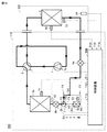
- FIG. 1 is a functional block diagram showing a configuration of an air conditioner 100 which is an example of the refrigeration cycle device according to the first embodiment.
- the main flow of the refrigerant is indicated by a thick line. The same applies to FIG. 4, FIG. 7 to FIG. 10, and FIG. 14 which will be described later.
- the air conditioner 100 includes an outdoor unit 110 and an indoor unit 120.
- the air conditioner 100 performs a cooling operation on the indoor space in which the indoor unit 120 is arranged.
- the outdoor unit 110 includes a compressor 1, a heat exchanger 3a (first heat exchanger), a heat exchanger 3b (second heat exchanger), an expansion valve 4a (first expansion valve), and a switching unit 7. (First switching unit), a control device 50, temperature sensors 11 to 14, and an outdoor fan (not shown) are included.
- the indoor unit 120 includes a heat exchanger 5 (third heat exchanger) and an indoor fan (not shown).
- the control device 50 may be included in the indoor unit 120, or may be provided separately from the outdoor unit 110 and the indoor unit 120.
- an arrow G1 indicates the direction of gravity around the heat exchanger 3b. The same applies to FIGS. 6 to 10, 14, and 16 which will be described later.
- the switching unit 7 includes a port P1 (first port), a port P2 (second port), and a port P3 (third port).
- the switching unit 7 selectively forms the flow path F1 (first flow path) and the flow path F2 (second flow path).
- the flow path F1 communicates between ports P1 and P2.
- the flow path F2 communicates with ports P1 and P3.
- the refrigerant is circulated in the compressor 1, the heat exchanger 3a, the port P1, the port P2, the heat exchanger 3b, the expansion valve 4a, and the heat exchanger 5 (first circulation direction). ) Cycles.
- the heat exchangers 3a and 3b integrally function as a condenser, and the heat exchanger 5 functions as an evaporator.
- the refrigerant flows in from the port P4 (fourth port), and the refrigerant flows out from the port P5 (fifth port).
- a fan is provided in each of the heat exchangers 3a, 3b, and 5.
- the fan blows air to the corresponding heat exchanger to increase the heat exchange efficiency between the refrigerant and the air in the heat exchanger.
- a line flow fan, a propeller fan, a turbo fan, or a sirocco fan can be used as the fan.
- a plurality of fans may be provided for one heat exchanger, or one fan may be provided for a plurality of heat exchangers.
- the control device 50 acquires the temperature T11 of the refrigerant passing through the heat exchanger 3a from the temperature sensor 11 installed in the middle part of the heat exchanger 3a.
- the controller 50 acquires the temperature T12 of the refrigerant flowing between the heat exchanger 3a and the switching unit 7 from the temperature sensor 12.
- the control device 50 acquires the temperature T13 of the refrigerant flowing between the heat exchanger 3b and the expansion valve 4a from the temperature sensor 13.
- the control device 50 acquires the temperature T14 of the indoor space where the indoor unit 120 is installed from the temperature sensor 14.
- the control device 50 controls the drive frequency of the compressor 1 by the command value fc, so that the compressor 1 per unit time is adjusted so that the temperature T14 of the indoor space becomes the target temperature (for example, the temperature set by the user). Control the amount of refrigerant to be discharged.
- the control device 50 calculates the degree of supercooling of the refrigerant flowing out from the heat exchanger functioning as a condenser using the temperatures T11 to T13.
- the pressure difference between the refrigerant discharged from the compressor 1 before being depressurized (high pressure side refrigerant) and the refrigerant being depressurized before being sucked into the compressor 1 (low pressure side refrigerant) is in a desired range.
- the opening of the expansion valve 4a is controlled so that the value becomes.
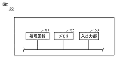
- FIG. 2 is a functional block diagram showing the configuration of the control device 50 of FIG.
- the control device 50 includes a processing circuit 51, a memory 52, and an input / output unit 53.
- the processing circuit 51 may be dedicated hardware or a CPU (Central Processing Unit) that executes a program stored in the memory 52.
- the processing circuit 51 includes, for example, a single circuit, a composite circuit, a programmed processor, a parallel programmed processor, an ASIC (Application Specific Integrated Circuit), and an FGA (Field Programmable Gate Array) or a combination of these is applicable.
- the processing circuit 51 is a CPU, the function of the control device 50 is realized by software, firmware, or a combination of software and firmware.
- the software or firmware is described as a program and stored in the memory 52.
- the processing circuit 51 reads and executes the program stored in the memory.
- the memory 52 includes a non-volatile or volatile semiconductor memory (for example, RAM (Random Access Memory), ROM (Read Only Memory), flash memory, EPROM (Erasable Programmable Read Only Memory), or EEPROM (Electrically Erasable Programmable Read Only Memory). )), magnetic disk, flexible disk, optical disk, compact disk, mini disk, or DVD (Digital Versatile Disc).
- the CPU is also called a central processing unit, a processing unit, an arithmetic unit, a microprocessor, a microcomputer, a processor, or a DSP (Digital Signal Processor).
- the operating state of the air conditioner 100 can be divided into high load operation and low load operation according to the load state of the compressor 1.
- the drive frequency of the compressor 1 in high load operation is higher than the drive frequency of the compressor 1 in low load operation.
- the operating state of the air conditioner 100 is determined from the command value fc to the compressor 1. For example, the operating state of the air conditioner 100 when the drive frequency of the compressor 1 represented by the command value fc is equal to or higher than the reference frequency is high load operation, and the operating state of the air conditioner 100 when the drive frequency is less than the reference frequency is Low load operation.
- the command value fc may be changed according to the temperatures T11 to T14.
- the temperature range is set stepwise (for example, 0°C or more and less than 1°C, 1°C or more and less than 2°C, and 2°C or more and less than 3°C), and the temperature difference between the temperature T14 and the target temperature of the indoor space is
- the drive frequency of the compressor 1 may be changed depending on which temperature range is included.
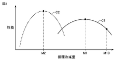
- FIG. 3 is a diagram schematically showing the relationship between the circulating refrigerant amount and the performance of the air conditioner 100 in each of the high load operation and the low load operation of the air conditioner 100 of FIG. 1.
- COP Coefficient of Performance
- the curve C1 shows the relationship between the amount of circulating refrigerant and the performance of the air conditioner 100 in high-load operation.
- a curve C2 shows the relationship between the circulating refrigerant amount and the performance of the air conditioner 100 in the low load operation.
- the amount of refrigerant M10 is the amount of refrigerant sealed in the air conditioner 100. Since a part of the refrigerant amount M10 is dissolved in the refrigerating machine oil stored in the compressor 1, the circulating refrigerant amount is smaller than the refrigerant amount M10.
- the performance of the air conditioner 100 is maximized when the amount of circulating refrigerant is M1.
- the refrigerant amount M10 is determined such that the refrigerant amount obtained by subtracting the amount of dissolution in the refrigerating machine oil from the refrigerant amount M10 becomes M1.
- the performance of the air conditioner 100 is maximized when the circulating refrigerant amount is M2 ( ⁇ M1). If the low load operation is performed while the amount of circulating refrigerant is M1, the performance of the air conditioner 100 is not maximized.
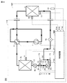
- the flow passage F2 is opened as shown in FIG.
- the heat exchanger 3b is formed and separated from the circulation channel of the refrigerant. The greater the amount of circulating refrigerant, the greater the degree of supercooling of the refrigerant flowing out of the heat exchanger functioning as a condenser. Therefore, whether or not the amount of circulating refrigerant is excessive is determined by the degree of supercooling.
- the refrigerant circulates in the circulation direction (second circulation direction) of the compressor 1, the heat exchanger 3a, the port P1, the port P3, the expansion valve 4a, and the heat exchanger 5.
- the circulation direction of the refrigerant is switched from the circulation direction of FIG. 1 to the circulation direction of FIG. 4, a part of the refrigerant remains in the heat exchanger 3b.
- the heat exchanger 3b is designed so that the refrigerant amount obtained by subtracting the refrigerant amount stored in the heat exchanger 3b from the circulating refrigerant amount M1 becomes M2. Since the heat exchanger 3b can be used as a container for adjusting the amount of circulating refrigerant in the air conditioner 100, a refrigerant container (for example, a receiver) separate from the heat exchanger is unnecessary. According to the air conditioner 100, it is possible to suppress the increase in size of the air conditioner 100 while improving the performance of the air conditioner 100.
- the flow passage F3 from the heat exchanger 3b to the expansion valve 4a is connected to the flow passage F4 (fourth flow passage) from the port P3 at the connection portion N1 (specific portion).
- the connecting portion N1 is formed at a position higher than the port P5.
- the height of the connecting portion N1 may be the same as the height of the port P5.
- the heat exchanger 3b is separated from the circulation flow path of the refrigerant, but the port P5 communicates with the circulation flow path, so the refrigerant is not sealed in the heat exchanger 3b. Even if the temperature of the heat exchanger 3b rises, the pressure of the refrigerant in the heat exchanger 3b hardly rises, so that the safety of the air conditioner 100 can be ensured.
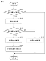
- FIG. 5 is a flowchart for explaining the flow of processing for the switching unit 7 performed by the control device 50 of FIG. 1 in low load operation.
- the process shown in FIG. 5 is called at regular time intervals by a main routine (not shown) that performs integrated control of the air conditioner 100.
- the step will be simply referred to as S.
- the control device 50 determines whether or not the flow path F1 is formed in S101.
- the control device 50 sets the supercooling degree of the refrigerant flowing out of the heat exchanger 3b in S102 to SC, and advances the process to S104.
- the control device 50 advances the processing to S104 with the degree of supercooling of the refrigerant flowing out from the heat exchanger 3a being SC in S103.
- the control device 50 determines whether or not the supercooling degree SC is larger than the reference value SC1 in S104. When supercooling degree SC is larger than reference value SC1 (YES in S104), control device 50 advances the process to S107. When supercooling degree SC is equal to or lower than reference value SC1 (NO in S104), control device 50 determines in S105 whether or not supercooling degree SC is smaller than reference value SC2 ( ⁇ SC1). When the degree of supercooling SC is equal to or higher than the reference value SC2 (NO in S106), control device 50 returns the process to the main routine. When the degree of supercooling SC is smaller than the reference value SC2 (YES in S105), the control device 50 forms the flow path F1 in S106 and advances the process to S107. The control device 50 forms the flow path F2 in S107 and returns the processing to the main routine.
- the reference values SC1 and SC2 are appropriately calculated by actual machine experiments or simulations.
- the reference values SC1 and SC2 are set to an upper limit value (for example, 5 ° C.) and a lower limit value (for example, 3 ° C.) of the allowable range (for example, 3 ° C. or higher and 5 ° C. or lower) of the design value of the supercooling degree SC, respectively.
- connection portion N1 between the flow paths F3 and F4 is formed at a position higher than the port P5
- the connecting portion N1A between the flow passages F3 and F4 is larger than the port P5. May be formed at a lower position.
- the height of the portion N2 may be the same as the height of the port P5.
- the refrigerant filled in the air conditioner 100 includes, for example, HFC (Hydro Fluoro Carbon) refrigerant, HFO (Hydro Fluoro Olefin) refrigerant, HC (Hydro Carbon) refrigerant, or non-azeotropic mixed refrigerant such as R454A.
- HFC Hydro Fluoro Carbon
- HFO Hydrofluoro Fluoro Olefin
- HC Hydrocarbon refrigerant
- non-azeotropic mixed refrigerant such as R454A.
- the refrigeration cycle device According to the refrigeration cycle device according to the first embodiment, it is possible to suppress the increase in size of the refrigeration cycle device while improving the performance of the refrigeration cycle device.
- Embodiment 2 In the first embodiment, the refrigeration cycle device that performs the cooling operation on the indoor space in which the indoor unit is arranged has been described. In the second embodiment, a refrigeration cycle device that performs a heating operation and a cooling operation on the indoor space and also performs a defrosting operation during the heating operation will be described.
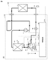
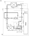
- FIG. 7 and 8 are functional block diagrams showing the configuration of the air conditioner 200, which is an example of the refrigeration cycle device according to the second embodiment, and the flow of the refrigerant in the cooling operation and the defrosting operation.
- a four-way valve 2 second switching unit
- an expansion valve 4b second expansion valve
- temperature sensors 15 and 16 are added to the configuration of the air conditioner 100 shown in FIG.
- 50 is replaced with 50B.
- the expansion valve 4b that is fully open is represented by a dotted line. The same applies to FIG. 9 described later.
- the expansion valve 4b is connected between the heat exchanger 3a and the port P1.
- the control device 50B fully opens the expansion valve 4b so that the heat exchangers 3a and 3b integrally function as a condenser.
- the control device 50B controls the expansion valves 4a and 4b, and the pressure difference between the high-pressure side refrigerant and the low-pressure side refrigerant is a value in a desired range.
- the opening degrees of the expansion valves 4a and 4b are controlled so that When the flow path F2 is formed, the opening degree of either one of the expansion valves 4a and 4b may be fully opened.
- the control device 50B controls the four-way valve 2 to switch the circulation direction of the refrigerant. In the low load operation of the cooling operation and the low load operation of the defrosting operation of the air conditioner 200, the processes shown in FIG. 5 are performed.
- FIG. 9 and FIG. 10 are functional block diagrams showing a configuration of an air conditioner 200, which is an example of the refrigeration cycle apparatus according to the second embodiment, and a refrigerant flow in heating operation.
- the refrigerant circulates in the direction opposite to the circulation direction shown in FIG. 7 (the third circulation direction).
- the heat exchangers 3a and 3b integrally function as an evaporator.
- the control device 50B fully opens the expansion valve 4b.
- the refrigerant circulates in the direction opposite to the circulation direction in FIG. 8 (the fourth circulation direction).
- the heat exchanger 3a functions as an evaporator.
- the control device 50B controls the expansion valves 4a and 4b so that the pressure difference between the high-pressure side refrigerant and the low-pressure side refrigerant becomes a value in a desired range.
- the opening degree of 4b is controlled.
- the control device 50B uses the temperatures T15 and T16 to calculate the degree of supercooling of the refrigerant flowing out of the heat exchanger 5.
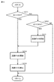
- FIG. 11 is a flowchart for explaining the flow of processing for the switching unit 7 performed by the control device 50 of FIG. 9 in the low load operation.
- the process shown in FIG. 11 is called at regular time intervals by a main routine (not shown) that performs integrated control of the air conditioner 200.
- a main routine not shown
- FIGS. 12 and 13 which will be described later.
- the control device 50B determines in S201 whether or not the supercooling degree SC is larger than the reference value SC3.
- the control device 50B advances the process to S204.
- control device 50B determines in S202 whether supercooling degree SC is smaller than reference value SC4 ( ⁇ SC3).
- the control device 50B returns the process to the main routine.
- the control device 50B When the degree of supercooling SC is smaller than the reference value SC4 (YES in S202), the control device 50B forms the flow path F1 in S203 and advances the process to S204. The control device 50B forms the flow path F2 in S204 and returns the process to the main routine.
- reference values SC3 and SC4 are appropriately calculated by actual machine experiments or simulations.
- reference values SC3 and SC4 are set to the upper limit value (for example, 3° C.) and the lower limit value (for example, 1° C.) of the allowable range (for example, 1° C. or more and 3° C. or less) of the design value of supercooling degree SC in the heating operation, respectively. To be done.
- FIG. 12 is a flowchart showing an example of the flow of the frost formation determination process performed by the control device 50B in the heating operation.
- the control device 50B determines in S211 whether or not the defrosting start condition of the heat exchanger 3b is satisfied.
- Examples of the defrosting start condition of the heat exchanger 3b include a condition that the temperature T13 is lower than the reference temperature Ds1 (for example, -3 ° C.). If the defrosting start condition of the heat exchanger 3b is not satisfied (NO in S211), the control device 50B returns the process to the main routine.
- the control device 50B determines in S212 whether the defrosting start condition of the heat exchanger 3a is satisfied. As a condition for starting defrosting of the heat exchanger 3a, a condition that the temperature T11 is lower than the reference temperature Ds2 (for example, -3 ° C.) can be mentioned. If the defrosting start condition of the heat exchanger 3a is not satisfied (NO in S212), the control device 50B returns the process to the main routine. When the defrosting start condition of the heat exchanger 3a is satisfied (YES in S212), the control device 50B advances the process to S213.
- the control device 50B forms the flow path F1 in S213, and advances the processing to S214.
- the controller 50B fully opens the expansion valve 4b in S214 and advances the process to S215.
- the control device 50B switches the circulation direction of the refrigerant in S215 to the circulation direction shown in FIG. 7, and returns the process to the main routine.
- both the heat exchangers 3a and 3b function as a condenser.
- the heat exchangers 3a and 3b are defrosted by the heat of condensation released from the refrigerant.
- FIG. 13 is a flowchart for explaining the flow of processing performed by the control device 50B of FIG. 7 during the reverse defrosting operation.
- the control device 50B determines in S221 whether or not the defrosting end condition of the heat exchanger 3a is satisfied.
- the defrosting end condition of the heat exchanger 3a a condition that the temperature T11 is higher than the reference temperature Df1 (for example, 0 ° C.) can be mentioned. If the defrosting end condition of the heat exchanger 3a is not satisfied (NO in S221), the control device 50B returns the process to the main routine.
- the control device 50B switches the circulation direction of the refrigerant in S222 and proceeds to the process in S223.
- the control device 50B determines in S223 whether or not the defrosting end condition of the heat exchanger 3b is satisfied.
- the defrosting end condition of the heat exchanger 3b a condition that the temperature T13 is higher than the reference temperature Df2 (for example, 0 ° C.) can be mentioned.
- control device 50B fully opens expansion valve 4b in S224 and returns the process to the main routine.
- the control device 50B controls the opening degree of the expansion valve 4a so that the pressure difference between the high-pressure side refrigerant and the low-pressure side refrigerant is within a desired range.
- the control device 50B fully opens the expansion valve 4a and returns the process to the main routine in S225.
- FIG. 14 shows the flow of the refrigerant when the defrosting end condition of the heat exchanger 3a is satisfied and the defrosting end condition of the heat exchanger 3b is not satisfied (when S225 of FIG. 13 is performed). It is a figure. As shown in FIG. 14, since the expansion valve 4a is fully open, the heat exchanger 3b functions as a condenser. The heat exchanger 3b is defrosted by the heat of condensation of the refrigerant. The heating by the condensation heat of the refrigerant is performed until the defrosting termination condition of the heat exchanger 3b is satisfied.
- the control device 50B controls the opening degree of the expansion valve 4b so that the pressure difference between the high-pressure side refrigerant and the low-pressure side refrigerant is within a desired range.
- the heating operation to be restarted may be either a high load operation or a low load operation.
- FIG. 15 is a flowchart showing another example of the flow of the frost formation determination process performed by the control device 50B in the heating operation.
- the flowchart shown in FIG. 15 is a flowchart in which S216 is added to the flowchart shown in FIG. 12 and the order of S212 and S213 is reversed.
- control device 50B forms the flow path F1 in S213 and advances the process to S212.
- control device 50B fully opens expansion valve 4a in S216 and returns the process to the main routine.
- the flow of the refrigerant in the air conditioner 200 after S216 is performed is the flow of the refrigerant shown in FIG.
- the expansion valve 4b since the expansion valve 4b is connected between the heat exchangers 3b and 3a, the liquid refrigerant can flow into the heat exchanger 3b with the expansion valve 4a fully opened. Since the liquid refrigerant can be stored in the heat exchanger 3b, the heat exchange is more than the case where there is no expansion valve 4b and the heat exchanger 3b stores the gas-liquid two-phase refrigerant after decompression by the expansion valve 4a.
- the vessel 3b can be downsized.
- the air conditioner 200 since the defrosting of the heat exchanger 3b can be continued while performing the heating operation, it is possible to reduce the decrease in the temperature of the indoor space due to the reverse defrosting operation. Further, when a non-azeotropic mixed refrigerant is sealed as the refrigerant, the vicinity of the port P5 of the heat exchanger 3b is likely to frost due to the influence of the temperature gradient. In the air conditioner 200, since the refrigerant having a relatively high temperature can flow into the heat exchanger 3b while continuing the heating operation, frost formation in the vicinity of the port P5 of the heat exchanger 3b can be suppressed. Furthermore, by suppressing the frost formation on the heat exchanger 3b, it is possible to prevent the frost formation on the heat exchanger 3a.
- the refrigeration cycle device According to the refrigeration cycle device according to the second embodiment, it is possible to suppress the increase in size of the refrigeration cycle device while improving the performance of the refrigeration cycle device in any of the cooling operation, the heating operation, and the defrosting operation. it can.
- Embodiment 3 In the first and second embodiments, the case where the first switching unit can selectively form the first flow path and the second flow path has been described. In the third embodiment, a case will be described in which the first switching unit can form a state in which both the first flow path and the second flow path are open.
- FIG. 16 is a functional block diagram showing the configuration of an air conditioner 300 which is an example of the refrigeration cycle device according to the third embodiment.
- the air conditioner 300 has a configuration in which the switching unit 7 and the control device 50B in FIG. 7 are replaced with a three-way valve 7C and a control device 50C, respectively. Other than these, it is the same, and therefore the description will not be repeated.
- the three-way valve 7C includes a port P31 (first port), a port P32 (second port), a port P33 (third port), and a passage F31 (first passage). , And a flow channel F32 (second flow channel).
- the flow path F31 communicates between ports P31 and P32.
- the flow path F32 communicates the ports P31 and P33.
- the three-way valve 7C can switch between opening and closing of the flow paths F31 and F32.
- FIG. 17 is a flow chart for explaining the flow of processing performed on the three-way valve 7C by the control device 50C of FIG. 16 in the low load operation of the cooling operation.
- the process shown in FIG. 17 is called at regular time intervals by a main routine (not shown) that performs integrated control of the air conditioner 300. The same applies to the processing shown in FIG.
- the control device 50C determines in S301 whether or not the flow path F31 is open.
- the control device 50C sets the supercooling degree of the refrigerant flowing from the heat exchanger 3b in S302 to SC, and advances the process to S304.
- the control device 50C sets the supercooling degree of the refrigerant flowing out of the heat exchanger 3a in S303 to SC, and advances the process to S304.
- the control device 50C determines whether or not the supercooling degree SC is larger than the reference value SC1 in S304. When the supercooling degree SC is larger than the reference value SC1 (YES in S304), the control device 50C proceeds to S305.
- control device 50C determines in S305 whether the supercooling degree SC is smaller than the reference value SC2. When the supercooling degree SC is equal to or higher than the reference value SC2 (NO in S305), the control device 50C returns the process to the main routine. When supercooling degree SC is smaller than reference value SC2 (YES in S305), control device 50C opens channel F31 in S306 and advances the process to S307.
- the control device 50C opens the channel F32 in S307 and advances the process to S308.
- the control device 50C closes the flow path F31 in S308 and returns the process to the main routine.
- both the flow passages F31 and F32 are opened, so that it is possible to suppress a rapid change in the amount of refrigerant stored in the heat exchanger 3b. As a result, it becomes easy to control the supercooling degree SC within the allowable range of the design value. Further, it is possible to suppress fluctuations in the performance of the air conditioner 200 (for example, the temperature at which air is blown from the indoor unit 120 to the indoor space).
- FIG. 18 is a flow chart for explaining the flow of processing performed on the three-way valve 7C by the control device 50C of FIG. 16 in the low load operation of the heating operation.
- the process shown in FIG. 11 is called at regular time intervals by a main routine (not shown) that performs integrated control of the air conditioner 200. The same applies to the processes shown in FIGS. 12 and 13 which will be described later.
- control device 50C determines in S311 whether or not the supercooling degree SC is larger than the reference value SC3.
- the control device 50C advances the process to S314.
- control device 50C determines in S312 whether supercooling degree SC is smaller than reference value SC4 ( ⁇ SC3).
- the control device 50C returns the process to the main routine.
- control device 50C opens channel F31 in S313 and advances the process to S314.
- the control device 50C opens the flow path F32 in S314 and advances the process to S315.
- the control device 50C closes the flow path F31 in S315 and returns the process to the main routine.
- FIG. 19 is a flowchart showing an example of the flow of the frost formation determination process performed by the control device 50C in the heating operation.
- the flowchart shown in FIG. 19 is a flowchart in which S213 shown in FIG. 12 is replaced by S323 and S324 is added between S323 and S214.
- the control is performed.
- the device 50C opens the flow path F31 in S323 and closes the flow path F32 in S324 to proceed with the process to S214.
- Control device 50C returns to the main routine after performing S214 and S215 as in the second embodiment.
- FIG. 20 is a flowchart showing another example of the flow of the frost formation determination process performed by the control device 50C in the heating operation.
- the flowchart shown in FIG. 20 is a flowchart in which S213 is replaced by S323 in FIG. 19 and S324 in FIG. 19 is added between S323 and S212.
- the control device 50C performs the process shown in FIG.
- the control device 50C opens the flow passage F31 in S323 and closes the flow passage F32 in S324. Then, the process proceeds to S212.
- the controller 50C performs S212 and S214 to S216 as in the second embodiment, and returns the process to the main routine.
- an electronic expansion valve may be connected to each of the flow paths F31 and F32 instead of the three-way valve 7C. Further, it is desirable that the amount of refrigerant flowing in each of the flow paths F31 and F32 can be adjusted.
- the refrigeration cycle device According to the refrigeration cycle device according to the third embodiment, it is possible to suppress the increase in size of the refrigeration cycle device while improving the performance of the refrigeration cycle device.
Landscapes
- Engineering & Computer Science (AREA)
- Physics & Mathematics (AREA)
- Mechanical Engineering (AREA)
- Thermal Sciences (AREA)
- General Engineering & Computer Science (AREA)
- Air Conditioning Control Device (AREA)
- Compression-Type Refrigeration Machines With Reversible Cycles (AREA)
Abstract
L'invention concerne un dispositif à cycle frigorifique (100) qui est doté : d'un compresseur (1) ; d'un premier échangeur de chaleur (3a) ; d'un deuxième échangeur de chaleur (3b) ; d'un troisième échangeur de chaleur (5) ; d'un premier détendeur (4a) et d'une première unité de commutation (7). La première unité de commutation (7) peut commuter un premier trajet d'écoulement (F1) et un second trajet d'écoulement (F2) entre l'ouverture et la fermeture. Si le premier trajet d'écoulement (F1) est ouvert, le fluide frigorigène circule dans la première direction de circulation du compresseur (1), du premier échangeur de chaleur (3a), du premier orifice (P1), du deuxième orifice (P2), du deuxième échangeur de chaleur (3b), du premier détendeur (4a) et du troisième échangeur de chaleur (5). Si le second trajet d'écoulement (F2) est ouvert, alors le fluide frigorigène circule dans la seconde direction de circulation du compresseur (1), du premier échangeur de chaleur (3a), du premier orifice (P1), du troisième orifice (P3), du premier détendeur (4a) et du troisième échangeur de chaleur (5). Lorsque la direction de circulation du fluide frigorigène est commutée de la première direction de circulation à la seconde direction de circulation, une partie du fluide frigorigène reste dans le second échangeur de chaleur (3b).
Priority Applications (5)
| Application Number | Priority Date | Filing Date | Title |
|---|---|---|---|
| JP2021503336A JP7118239B2 (ja) | 2019-03-06 | 2019-03-06 | 冷凍サイクル装置 |
| CN201980093345.7A CN113518886B (zh) | 2019-03-06 | 2019-03-06 | 制冷循环装置 |
| PCT/JP2019/008866 WO2020179015A1 (fr) | 2019-03-06 | 2019-03-06 | Dispositif à cycle frigorifique |
| EP19917871.6A EP3936786B1 (fr) | 2019-03-06 | 2019-03-06 | Dispositif à cycle frigorifique |
| ES19917871T ES2961815T3 (es) | 2019-03-06 | 2019-03-06 | Dispositivo de ciclo de refrigeración |
Applications Claiming Priority (1)
| Application Number | Priority Date | Filing Date | Title |
|---|---|---|---|
| PCT/JP2019/008866 WO2020179015A1 (fr) | 2019-03-06 | 2019-03-06 | Dispositif à cycle frigorifique |
Publications (1)
| Publication Number | Publication Date |
|---|---|
| WO2020179015A1 true WO2020179015A1 (fr) | 2020-09-10 |
Family
ID=72338482
Family Applications (1)
| Application Number | Title | Priority Date | Filing Date |
|---|---|---|---|
| PCT/JP2019/008866 Ceased WO2020179015A1 (fr) | 2019-03-06 | 2019-03-06 | Dispositif à cycle frigorifique |
Country Status (5)
| Country | Link |
|---|---|
| EP (1) | EP3936786B1 (fr) |
| JP (1) | JP7118239B2 (fr) |
| CN (1) | CN113518886B (fr) |
| ES (1) | ES2961815T3 (fr) |
| WO (1) | WO2020179015A1 (fr) |
Citations (6)
| Publication number | Priority date | Publication date | Assignee | Title |
|---|---|---|---|---|
| JPS5860168A (ja) * | 1981-07-09 | 1983-04-09 | テイ−アイ(グル−プ・サ−ビシ−ズ)リミテツド | 熱交換器 |
| JPH01116366U (fr) * | 1988-01-29 | 1989-08-04 | ||
| JP2006317063A (ja) * | 2005-05-12 | 2006-11-24 | Sharp Corp | 空気調和機 |
| JP2009041829A (ja) * | 2007-08-08 | 2009-02-26 | Panasonic Corp | 空気調和装置 |
| JP2015087065A (ja) | 2013-10-31 | 2015-05-07 | シャープ株式会社 | 空気調和機 |
| JP2018087675A (ja) * | 2016-11-30 | 2018-06-07 | ダイキン工業株式会社 | 冷凍装置 |
Family Cites Families (8)
| Publication number | Priority date | Publication date | Assignee | Title |
|---|---|---|---|---|
| JPS5860168U (ja) * | 1981-10-16 | 1983-04-22 | 三洋電機株式会社 | 冷凍装置 |
| CN201335568Y (zh) * | 2008-12-27 | 2009-10-28 | 广东美的电器股份有限公司 | 空调室外机的除霜系统 |
| JP5755490B2 (ja) * | 2011-04-18 | 2015-07-29 | トヨタ自動車株式会社 | 冷却装置 |
| US9605885B2 (en) * | 2013-03-14 | 2017-03-28 | Mitsubishi Electric Corporation | Air conditioning system including pressure control device and bypass valve |
| JP6017058B2 (ja) * | 2013-10-24 | 2016-10-26 | 三菱電機株式会社 | 空気調和装置 |
| JP6319334B2 (ja) * | 2016-01-15 | 2018-05-09 | ダイキン工業株式会社 | 冷凍装置 |
| CN105758075A (zh) * | 2016-04-01 | 2016-07-13 | 珠海格力电器股份有限公司 | 一种分段式制热除霜的空调系统及其制热除霜控制方法 |
| CN206247522U (zh) * | 2016-11-07 | 2017-06-13 | 宁波甬凌环境设备有限公司 | 一种三联供空气源热泵系统 |
-
2019
- 2019-03-06 WO PCT/JP2019/008866 patent/WO2020179015A1/fr not_active Ceased
- 2019-03-06 CN CN201980093345.7A patent/CN113518886B/zh active Active
- 2019-03-06 ES ES19917871T patent/ES2961815T3/es active Active
- 2019-03-06 JP JP2021503336A patent/JP7118239B2/ja not_active Expired - Fee Related
- 2019-03-06 EP EP19917871.6A patent/EP3936786B1/fr active Active
Patent Citations (6)
| Publication number | Priority date | Publication date | Assignee | Title |
|---|---|---|---|---|
| JPS5860168A (ja) * | 1981-07-09 | 1983-04-09 | テイ−アイ(グル−プ・サ−ビシ−ズ)リミテツド | 熱交換器 |
| JPH01116366U (fr) * | 1988-01-29 | 1989-08-04 | ||
| JP2006317063A (ja) * | 2005-05-12 | 2006-11-24 | Sharp Corp | 空気調和機 |
| JP2009041829A (ja) * | 2007-08-08 | 2009-02-26 | Panasonic Corp | 空気調和装置 |
| JP2015087065A (ja) | 2013-10-31 | 2015-05-07 | シャープ株式会社 | 空気調和機 |
| JP2018087675A (ja) * | 2016-11-30 | 2018-06-07 | ダイキン工業株式会社 | 冷凍装置 |
Also Published As
| Publication number | Publication date |
|---|---|
| CN113518886B (zh) | 2022-11-11 |
| ES2961815T3 (es) | 2024-03-14 |
| EP3936786A1 (fr) | 2022-01-12 |
| JPWO2020179015A1 (ja) | 2021-12-02 |
| JP7118239B2 (ja) | 2022-08-15 |
| EP3936786A4 (fr) | 2022-03-16 |
| CN113518886A (zh) | 2021-10-19 |
| EP3936786B1 (fr) | 2023-10-04 |
Similar Documents
| Publication | Publication Date | Title |
|---|---|---|
| JP6899928B2 (ja) | 冷凍サイクル装置 | |
| JP7034319B2 (ja) | 空気調和機 | |
| WO2015162696A1 (fr) | Climatiseur et son procédé de commande de dégivrage | |
| JP6548742B2 (ja) | 空気調和装置 | |
| JP2005077084A (ja) | 空気調和機及びその制御方法 | |
| JP7105933B2 (ja) | 冷凍装置の室外機およびそれを備える冷凍装置 | |
| JP5403093B2 (ja) | 空気調和装置 | |
| JP6672619B2 (ja) | 空調システム | |
| US8769968B2 (en) | Refrigerant system and method for controlling the same | |
| JP2009133557A (ja) | 空気調和装置 | |
| JP2017009269A5 (fr) | ||
| JP7407920B2 (ja) | 冷凍サイクル装置 | |
| JP7118239B2 (ja) | 冷凍サイクル装置 | |
| JPWO2020174687A1 (ja) | 空気調和機の室外機 | |
| JP6529579B2 (ja) | ヒートポンプシステム | |
| JP7034325B2 (ja) | 空調装置 | |
| WO2020144843A1 (fr) | Appareil de climatisation | |
| JP2006317063A (ja) | 空気調和機 | |
| WO2022249394A1 (fr) | Dispositif à cycle frigorifique | |
| WO2021156964A1 (fr) | Climatiseur | |
| AU2023244654B2 (en) | Air conditioner | |
| JPWO2021075013A5 (fr) | ||
| JP7046234B2 (ja) | 冷凍サイクル装置 | |
| KR101669971B1 (ko) | 공기조화장치 | |
| JP6602397B2 (ja) | 冷凍装置 |
Legal Events
| Date | Code | Title | Description |
|---|---|---|---|
| 121 | Ep: the epo has been informed by wipo that ep was designated in this application |
Ref document number: 19917871 Country of ref document: EP Kind code of ref document: A1 |
|
| ENP | Entry into the national phase |
Ref document number: 2021503336 Country of ref document: JP Kind code of ref document: A |
|
| NENP | Non-entry into the national phase |
Ref country code: DE |
|
| ENP | Entry into the national phase |
Ref document number: 2019917871 Country of ref document: EP Effective date: 20211006 |