WO2020179151A1 - 車上通信装置および鉄道車両 - Google Patents
車上通信装置および鉄道車両 Download PDFInfo
- Publication number
- WO2020179151A1 WO2020179151A1 PCT/JP2019/046135 JP2019046135W WO2020179151A1 WO 2020179151 A1 WO2020179151 A1 WO 2020179151A1 JP 2019046135 W JP2019046135 W JP 2019046135W WO 2020179151 A1 WO2020179151 A1 WO 2020179151A1
- Authority
- WO
- WIPO (PCT)
- Prior art keywords
- information
- wave
- deterioration
- communication device
- unit
- Prior art date
- Legal status (The legal status is an assumption and is not a legal conclusion. Google has not performed a legal analysis and makes no representation as to the accuracy of the status listed.)
- Ceased
Links
Images

Classifications
-
- B—PERFORMING OPERATIONS; TRANSPORTING
- B61—RAILWAYS
- B61L—GUIDING RAILWAY TRAFFIC; ENSURING THE SAFETY OF RAILWAY TRAFFIC
- B61L15/00—Indicators provided on the vehicle or train for signalling purposes
- B61L15/0081—On-board diagnosis or maintenance
-
- B—PERFORMING OPERATIONS; TRANSPORTING
- B61—RAILWAYS
- B61L—GUIDING RAILWAY TRAFFIC; ENSURING THE SAFETY OF RAILWAY TRAFFIC
- B61L3/00—Devices along the route for controlling devices on the vehicle or train, e.g. to release brake or to operate a warning signal
- B61L3/02—Devices along the route for controlling devices on the vehicle or train, e.g. to release brake or to operate a warning signal at selected places along the route, e.g. intermittent control simultaneous mechanical and electrical control
- B61L3/08—Devices along the route for controlling devices on the vehicle or train, e.g. to release brake or to operate a warning signal at selected places along the route, e.g. intermittent control simultaneous mechanical and electrical control controlling electrically
- B61L3/12—Devices along the route for controlling devices on the vehicle or train, e.g. to release brake or to operate a warning signal at selected places along the route, e.g. intermittent control simultaneous mechanical and electrical control controlling electrically using magnetic or electrostatic induction; using radio waves
- B61L3/121—Devices along the route for controlling devices on the vehicle or train, e.g. to release brake or to operate a warning signal at selected places along the route, e.g. intermittent control simultaneous mechanical and electrical control controlling electrically using magnetic or electrostatic induction; using radio waves using magnetic induction
-
- B—PERFORMING OPERATIONS; TRANSPORTING
- B61—RAILWAYS
- B61L—GUIDING RAILWAY TRAFFIC; ENSURING THE SAFETY OF RAILWAY TRAFFIC
- B61L3/00—Devices along the route for controlling devices on the vehicle or train, e.g. to release brake or to operate a warning signal
- B61L3/02—Devices along the route for controlling devices on the vehicle or train, e.g. to release brake or to operate a warning signal at selected places along the route, e.g. intermittent control simultaneous mechanical and electrical control
- B61L3/08—Devices along the route for controlling devices on the vehicle or train, e.g. to release brake or to operate a warning signal at selected places along the route, e.g. intermittent control simultaneous mechanical and electrical control controlling electrically
- B61L3/12—Devices along the route for controlling devices on the vehicle or train, e.g. to release brake or to operate a warning signal at selected places along the route, e.g. intermittent control simultaneous mechanical and electrical control controlling electrically using magnetic or electrostatic induction; using radio waves
- B61L3/125—Devices along the route for controlling devices on the vehicle or train, e.g. to release brake or to operate a warning signal at selected places along the route, e.g. intermittent control simultaneous mechanical and electrical control controlling electrically using magnetic or electrostatic induction; using radio waves using short-range radio transmission
Definitions
- the present invention relates to an on-vehicle communication device and a railway vehicle.
- the on-board child of the on-board communication device mounted on the vehicle transmits and receives information waves to and from the ground child of the ground communication device installed on the road.
- the data such as the speed limit and the position information of the vehicle obtained from the ground is used for controlling the operation of the vehicle.
- terrestrial communication devices There are two types of terrestrial communication devices: powered terrestrial communication devices that receive power from the ground and non-powered terrestrial communication devices that are activated by power waves transmitted from the on-board communication device. Both terrestrial communication devices transmit and receive information waves at frequencies different from power waves.
- the unpowered ground communication device in order to activate the unpowered ground communication device and communicate reliably, it is necessary to transmit stable power from the car top to the ground.
- the power wave transmitted from the car top may fall outside the specified range. Therefore, it may be provided with a function of monitoring that the electric power wave of the on-board element is within the specified range.
- Patent Document 1 a feedback control that includes a power wave transmission level monitor unit that monitors a power wave level transmitted to a car top and adjusts a power wave transmission set value according to the power wave level acquired by the monitor unit. And “determine whether or not the output value of the power wave monitor is out of the specified range” is described.
- Patent Document 1 a failure is detected when the power wave level is out of the specified range.
- Patent Document 1 since the power wave level is fed back to adjust the power wave output level, the power wave level is kept within the specified range. Therefore, the power wave level will be out of the specified range only when a failure that cannot be covered by the feedback control occurs. Therefore, when an abnormality is detected at the power wave level, the failed device must be replaced, which may cause a failure in operation.
- the present invention provides a technique for detecting a sign of failure of an on-board communication device.
- One of the typical on-board communication devices of the present invention is an on-board communication device that transmits an electric wave and receives an information wave to a ground element installed on a railroad track, and generates an electric wave.
- the power wave transmitter, the train top that transmits the power wave generated by the power wave transmitter to the ground element and receives the information wave transmitted by the ground element, and the output of the power wave are detected and stabilized at the specified output.
- a deterioration diagnosis unit that outputs information based on the feedback command value of the feedback unit as information indicating a failure sign (hereinafter, “deterioration information”).
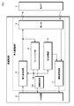
- FIG. 1 is a block diagram showing an on-vehicle communication device according to the first embodiment.
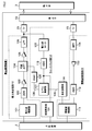
- FIG. 2 is a block diagram showing a detailed configuration of each part of the on-board communication device.
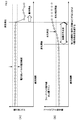
- FIG. 3 is an explanatory diagram for comparing and explaining the secular change of the power wave level and the secular change of the feedback command value.
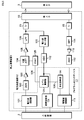
- FIG. 4 is a block diagram illustrating the on-vehicle communication device according to the second embodiment.
- FIG. 5 is a block diagram illustrating the on-vehicle communication device according to the third embodiment.
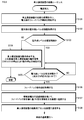
- FIG. 6 is a flowchart showing a startup sequence of the on-board communication device according to the fourth embodiment.
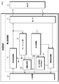
- FIG. 7 is a block diagram showing an on-vehicle communication device according to the fifth embodiment.
- FIG. 1 is a block diagram showing an on-board communication device mounted on a railroad vehicle R.
- the railway vehicle R includes an on-board communication device 1 and a host device 2.
- the on-board communication device 1 includes an electric power wave transmitting unit 10, an information wave receiving unit 11, a feedback unit 12, an on-board child 13, a deterioration diagnosing unit 14, and a failure diagnosing unit 124.
- the power wave transmission unit 10 generates a power wave according to a power wave transmission command from the higher-level device 2.
- the generated power wave is transmitted to the ground element 3 of the ground communication device via the on-board element 13.
- the feedback unit 12 monitors the output level of the power wave transmission unit 10 and suppresses the gain of the power wave when the output level is higher than the target value, and increases the gain of the power wave when the output level is lower than the target value. I do.
- the failure diagnosis unit 124 determines that the electric power wave transmission unit 10 or the vehicle top 13 which is the load has failed. , And sends a signal notifying the upper device 2 of the failure.
- the information wave receiving unit 11 receives the information wave transmitted by the ground element 3 of the terrestrial communication device by the on-board element 13.
- the information wave receiving unit 11 demodulates this information wave and transmits it as an information wave telegram to the host device 2.
- the deterioration diagnosis unit 14 acquires a command value (hereinafter referred to as “feedback command value 126”) such as a power wave gain command output by the feedback unit 12.
- the deterioration diagnosing unit 14 uses the feedback command value 126 itself, feedback information calculated from the feedback command value 126, information as to whether or not the feedback command value 126 exceeds a deterioration determination threshold, and a change with time of the feedback command value 126.
- the deterioration diagnosis information and the like estimated from the above are transmitted to the information wave receiving unit 11 as deterioration information (information indicating a failure sign) of the power wave transmission system.
- the information wave receiving unit 11 attaches an "identifier such as a flag indicating deterioration information" to the deterioration information received from the deterioration diagnosis unit 14, and sets the same transmission path as the information wave telegram of the information wave received from the on-board child 13. It is used to transmit to the host device 2.
- an "identifier such as a flag indicating deterioration information”
- FIG. 2 is a block diagram showing a detailed configuration of each part of the on-board communication device.
- the power wave transmission unit 10 controls the power wave frequency setting and output ON/OFF according to the power wave transmission command of the higher-level device 2, and the power wave control unit 101 controls the power wave control unit 101.
- the DDS 102 Direct Digital Synthesizer
- the preamplifier 103 that amplifies the sine wave signal of the DDS 102
- the output of the preamplifier 103 are attenuated to adjust the level according to the feedback command value 126.
- the information wave receiving unit 11 converts the output of the bandpass filter 114 that removes unnecessary frequencies of the information wave received from the vehicle carrier 13, the preamplifier 113 that amplifies the output of the bandpass filter 114, and the output of the preamplifier 113 into a digital signal.
- A/D converter 112 and an information wave control unit 111 that decodes the converted digital signal and sends it to the higher-level device 2 as an information wave message.
- an insulating transformer 15 and a balanced/unbalanced transformer 15 are provided between the power wave transmitting unit 10 and the upper rotor 13 and between the information wave receiving unit 11 and the upper rotor 13, respectively. ..
- the feedback unit 12 measures the output current of the power wave transmission unit 10 and outputs a power wave monitor signal corresponding to the power wave level, and an A/W that converts the output of the power wave monitor 123 into a digital signal.
- a level control unit that outputs a feedback command value 126 for increasing the attenuation of the variable attenuator 104 when the D converter 112 and the digitally converted power wave monitor signal are higher than the target value and decreasing the attenuation when the signal is lower than the target value.
- 121 and a D/A converter 125 that converts the feedback command value 126 into an analog signal.
- the failure diagnosis unit 124 determines that the power wave transmission unit 10 has failed, and sends a signal to the upper level device 2 to notify the detection of the failure. ..
- the deterioration diagnosis unit 14 acquires the same signal as the feedback command value 126 that controls the variable attenuator 104 from the level control unit 121.
- the deterioration diagnosis unit 14 attaches an identifier indicating that to the deterioration information based on the feedback command value 126, and outputs the deterioration information to the information wave control unit 111.
- the information wave control unit 111 preferentially transmits the information wave telegram of the information wave received from the on-board child 13 to the higher-level device 2, and when the information wave is not received from the on-board child 13, the deterioration diagnosis unit 14 sends the information wave.
- the deterioration information is transmitted to the host device 2.
- the upper level device 2 can grasp the deterioration status of the power wave transmission system of the on-board communication device 1 based on the deterioration information received via the information wave control unit 111.
- FIG. 3 is an explanatory diagram for comparatively explaining the secular change of the power wave level and the secular change of the feedback command value.
- the power wave level is stably maintained in the specified range by feedback control. Therefore, the power wave level goes out of the specified range only when an abnormality that cannot be covered by the feedback control occurs. Therefore, it is difficult for the failure diagnosis unit 124 to detect a sign of failure such as natural deterioration only by monitoring the power wave level.
- the failure diagnosis unit 124 detects an abnormality in the electric power wave level, it is necessary to deal with the failure (such as replacement of the on-board communication device 1), which hinders the operation of the railway train.
- the feedback command value 126 gradually changes to compensate for a gradual deterioration phenomenon such as a decrease in the transmission efficiency of the power wave. Therefore, the deterioration diagnosis unit 14 of the first embodiment monitors the information based on the feedback command value 126, so that even in a situation where the power wave level is stabilized by the feedback control, deterioration that may occur in the power wave transmission system, etc. The sign of failure can be grasped.
- the deterioration diagnosis unit 14 outputs the feedback command value 126 itself or feedback information calculated from the feedback command value 126 as deterioration information.
- the deterioration diagnosis unit 14 makes a deterioration judgment when the feedback command value 126 exceeds a predetermined deterioration judgment threshold value, and outputs the deterioration judgment result as deterioration information.
- the deterioration diagnosis unit 14 accumulates information based on the feedback command value 126 as a history and outputs the deterioration information when a change in the feedback command value 126 is detected.
- the deterioration diagnosis unit 14 estimates the progress of deterioration based on the change over time of the feedback command value 126, and outputs the estimation result as deterioration information.
- the sign of a failure in the power wave transmission system can be detected based on the feedback command value 126.
- the deterioration diagnosis unit 14 detects a sign of a failure before the failure diagnosis unit 124 detects a failure. Therefore, maintenance such as replacement of the device can be performed before the failure, and thus the railway vehicle Improves the operating rate.
- the deterioration diagnosis unit 14 transmits the feedback command value 126 itself or feedback information calculated from the feedback command value to the higher-level device 2 as deterioration information. Therefore, in the host device 2 or the vehicle management center beyond that, it is possible to detect a sign of a failure in the power wave transmission system based on the feedback command value 126 itself or the feedback information.
- the deterioration diagnosis unit 14 determines whether the feedback command value exceeds the deterioration determination threshold value, and outputs that the feedback command value exceeds the deterioration determination threshold value as deterioration information. Therefore, the host device 2 and the control center of the vehicle beyond it do not receive the deterioration information in an unnecessary and urgent situation where the deterioration has not progressed, and receive the deterioration information in a situation where the deterioration has progressed to some extent. As a result, there is an advantage that the burden of maintenance management is reduced in the host device 2 and the vehicle management center beyond it.
- the deterioration diagnosis unit 14 accumulates information based on the feedback command value 126 as a history and outputs the deterioration information at the time when the change in the feedback command value 126 is detected. Therefore, the host device 2 and the control center of the vehicle beyond it do not receive the deterioration information in an unnecessary and urgent situation where the deterioration has not progressed, and receive the deterioration information in a situation where the deterioration has progressed to some extent. As a result, there is an advantage that the burden of maintenance and management is reduced in the host device 2 and the vehicle management center beyond that.
- the deterioration diagnosis unit 14 estimates the progress of deterioration based on the change over time of the feedback command value 126 and outputs it as deterioration information. Therefore, the host device 2 and the vehicle management center beyond it do not need to estimate the progress of deterioration. As a result, there is an advantage that the burden of maintenance and management is reduced in the host device 2 and the vehicle management center beyond that.
- the information wave receiving unit 11 transmits the deterioration information to the host device 2 using the same transmission path as the information wave telegram. Therefore, wiring for a new transmission path becomes unnecessary, and it becomes possible to reduce the circuit scale and eliminate the need for circuit change.
- FIG. 4 is a block diagram illustrating the on-vehicle communication device according to the second embodiment.
- the on-vehicle communication device 1 includes a simulated information wave transmission unit 16 in addition to the configuration described in the first embodiment (FIG. 1).
- the on-board element 13 is a power wave transmitter 131 for transmitting the power wave to the ground element, a power wave monitoring antenna 132 for monitoring the transmission status of the power wave, and an information wave for receiving the information wave from the ground element.
- An information wave receiver 133 and a simulated information wave transmitter 134 for transmitting a simulated information wave from the vehicle are provided.
- the same reference number as Example 1 (FIG. 1) is attached
- the higher-level device 2 gives the simulated information wave transmitting unit 16 an instruction for an information wave reception status test.
- the simulated information wave transmitter 16 gives the simulated information wave transmitter 134 a simulated information wave that simulates the information wave from the ground element, in consideration of the timing when the information wave receiver 11 does not receive the information wave.
- the simulated information wave transmitter 134 sends the simulated information wave to the information wave receiver 133.
- the information wave receiving unit 11 has a reception status, reception level, frequency information, phase information, waveform distortion information, attenuation amount, noise amount, and signal-to-noise ratio (S / N) for the simulated information wave received by the information wave receiver 133.
- S / N signal-to-noise ratio
- Carrier-to-noise ratio (C / N) decoding information amount, code error rate, sideband wave amount, modulation amount, harmonic component amount, etc. are detected as information that is the basis of deterioration diagnosis, and deterioration of the information wave receiving system Information.
- the information wave receiving unit 11 assigns an identifier to that effect to the deterioration information of the reception system of the information wave, and transmits it to the higher-level device 2 using the same transmission path as the information wave message.
- the power wave monitoring antenna 132 receives a part of the power wave transmitted from the power wave transmitter 131 and outputs it to the deterioration diagnosis unit 14.
- the deterioration diagnosis unit 14 detects the reception level of the power wave by the power wave monitoring antenna 132 and its change as information on the deterioration of the power wave transmission system. For example, the deterioration diagnosis unit 14 detects the deterioration of the power wave transmission system based on the difference change between the signal level of the power wave input to the on-board element and the reception level of the power wave by the power wave monitoring antenna 132. And outputs it as a kind of deterioration information.
- the simulated information wave transmitter 16 sends the simulated information wave from the simulated information wave transmitter 134, and the information wave receiver 11 receives the simulated information wave by way of the information wave receiver 133.
- the deterioration status (or failure status) of the reception system can be detected.
- the deterioration diagnosis unit 14 determines the power wave transmission system based on the change in the difference between the signal level of the power wave input to the vehicle top and the reception level of the power wave by the power wave monitoring antenna. Outputs the deterioration status (or failure status). Therefore, it is possible to detect a deterioration phenomenon such as a decrease in the reception level of the power wave monitoring antenna 132, even though the signal level of the power wave input to the train car is sufficient.
- the deterioration diagnosis unit 14 monitors a part of the power wave via the power wave monitoring antenna 132 to detect the deterioration status (or failure status) of the power wave transmission system. You can
- PLD program logic device
- FIG. 5 is a block diagram illustrating the on-vehicle communication device according to the third embodiment.
- the on-vehicle communication device 1 includes a PLD 17.
- the PLD 17 includes a deterioration diagnosis unit 14, a level control unit 121 which is at least a part of the feedback unit 12, an information wave control unit 111 which is at least a part of the information wave reception unit 11, and a failure diagnosis unit 124.
- a circuit configured by describing the program logic of and is implemented. Since the other configurations are the same as those of the first embodiment (FIG. 2), duplicate description here will be omitted.
- Example 3 has the following effects in addition to the effects of Example 1 described above.
- the present invention can be easily and inexpensively introduced into the conventional on-board communication device by simply replacing the PLD of the on-board communication device including the components other than the deterioration diagnosis unit 14 with the PLD 17 of the third embodiment. Become.
- the program logic that realizes the deterioration diagnosis unit 14 to the PLD of the on-vehicle communication device including the components other than the deterioration diagnosis unit 14, the conventional vehicle can be used.
- the present invention can be easily and inexpensively introduced into the upper communication device.
- the fourth embodiment for acquiring the deterioration information at the timing of turning on (starting) the power of the onboard communication device.
- the device configuration of the fourth embodiment any of the device configurations of the first to third embodiments can be adopted, and thus the duplicate description of the configuration of the fourth embodiment will be omitted.
- FIG. 6 is a flowchart showing a startup sequence of the on-board communication device according to the fourth embodiment. Hereinafter, description will be given along the step numbers shown in FIG.
- Step S101 The on-board communication device 1 performs an initialization process in response to power-on. After the completion of the initialization process, the feedback unit 12 starts the feedback control for transmitting the power wave.
- Step S102 The failure diagnosis unit 124 acquires information on the power wave level from the feedback unit 12.
- Step S103 The failure diagnosis unit 124 determines whether or not the power wave level is within the specified range defined by the feedback control. If the power wave level falls within the specified range, the failure diagnosis unit 124 shifts the operation to step S105. On the other hand, when the power wave level deviates from the specified range, the failure diagnosis unit 124 shifts the operation to step S104.
- Step S104 The failure diagnosis unit 124 stops the operation of the on-board communication device 1 for the purpose of fail-safe because the power wave level is out of the specified range despite the feedback control. Further, the failure diagnosis unit 124 stops the operation signal (clock) transmitted from the on-board communication device 1 to the host device 2. By stopping this operation signal (clock), the host device 2 detects the operation stop (failure occurrence) of the on-board communication device 1, and further notifies the host monitoring center or the like of the maintenance request for the on-board communication device 1. As a result, the series of startup sequences is interrupted here.
- Step S105 Since the power wave level falls within the specified range, the failure diagnosis unit 124 continues the startup sequence. Subsequently, the deterioration diagnosis unit 14 determines whether or not the power wave level is in a stable state, based on the instantaneous fluctuation width of the feedback command value and the like. This is because, when the ground element 3 is close to the on-board element 13, the power wave level and the feedback command value 126 change instantaneously, which is not suitable for detecting deterioration information during that period. If the power wave level is fluctuating, the deterioration diagnosis unit 14 waits for the operation until the ground element 3 separates from the car top 13 and the power wave level becomes stable. On the other hand, when the power wave level is in a stable state, the deterioration diagnosis unit 14 shifts the operation to step S106.
- Step S106 The deterioration diagnosis unit 14 acquires information on the feedback command value 126 from the feedback unit 12.
- the deterioration diagnosis unit 14 generates deterioration information based on the feedback command value 126 and outputs the deterioration information to the information wave receiving unit 11.
- Step S107 The information wave receiving unit 11 transmits the deterioration information based on the feedback command value 126 to the higher-level device 2 using the transmission path of the information wave message.
- Step S108 The on-board communication device 1 transmits the completion of the activation sequence to the host device 2. When the series of startup sequences described above is completed, the operation is shifted to the normal operation of the railway vehicle R.
- Example 4 In Example 4, in addition to the effects of Examples 1 to 3 described above, the following effects are exhibited.
- deterioration information is detected when the on-board communication device 1 is activated and transmitted to the host device 2. Therefore, the transmission timing of the deterioration information does not overlap with the reception timing of the information wave or the transmission timing of the information wave telegram. Therefore, it is possible to eliminate the risk that the timing of transmitting the information wave message of the information wave to the higher-level device 2 is delayed or the reception of the information wave fails. Therefore, even if the operation of deterioration diagnosis is newly added, the operation of the train is not easily disturbed.
- the deterioration information can be obtained each time the onboard communication device 1 is activated. Normally, the railway vehicle R repeats power-off and power-on once every operating day. Therefore, the deterioration information can be obtained once every operating day. Since the signs of failure such as deterioration change little by little over a long period of time, it can be said that the acquisition cycle of deterioration information is sufficient once a day.
- deterioration information is acquired at a timing instructed from the outside and the deterioration information is further notified into the rack of the railway vehicle R.
- FIG. 7 is a diagram showing the on-vehicle communication device 1 in the fifth embodiment.
- the deterioration information request signal 18 is transmitted from the host device 2 or the like to the deterioration diagnosis unit 14. Further, from the deterioration diagnosis unit 14, a switching signal for lighting display is transmitted to the in-rack display 19. Note that other configurations are the same as those in the first embodiment (FIG. 1), and thus redundant description will be omitted here.
- the deterioration diagnosis unit 14 detects the deterioration information and transmits it to the higher-level device 2 in response to a request from the deterioration information request signal 18 at any time. Further, when the deterioration diagnosis unit 14 determines deterioration (a sign of failure) based on the deterioration information, the display (LED or the like) indicating the deterioration of the in-rack display 19 is switched to an alarm state such as lighting or blinking.
- Example 5 has the following effects in addition to the effects of Example 1 described above.
- deterioration information can be acquired at any time at the timing of the deterioration information request signal 18 given from the outside. Therefore, since deterioration information can be acquired at any time according to the maintenance work of the railway vehicle R, deterioration (a sign of failure) is detected at the same timing as the maintenance work, and the on-board communication device 1 and the like are replaced and maintained. It becomes possible to do.
- the deterioration detection can be notified to the outside of the onboard communication device 1. Therefore, it is possible to urge the operator and maintenance worker of the railway vehicle R to replace the on-board communication device 1 in a timely manner, so that the operation efficiency of the railway vehicle R is improved.
- the present invention is not limited to the above-mentioned examples, and includes various modifications.
- the above-described first to fifth embodiments have been described in detail in order to explain the present invention in an easy-to-understand manner, and are not necessarily limited to those having all the configurations described.
- a part of the configuration of a certain embodiment can be replaced with the configuration of another embodiment, and the configuration of a certain embodiment can be combined with the configuration of another embodiment.
- the deterioration diagnosis unit 14 outputs deterioration information based on the feedback command value 126.
- the deterioration diagnosis unit 14 may output the deterioration information based on the feedback command value 126 in cooperation with the deterioration estimation function of the information wave control unit 111, an external device, or the like.
- the configuration of the DDS 102, the variable attenuator 104, the power wave monitor 123, the A / D converter 112, the D / A converter 125 and the like shown in the above-described embodiment (see FIG. 2) is one of the means.
- the invention is not limited to these configurations.
- a crystal oscillator and a low-pass filter may be used to generate a sine wave, or the power wave voltage may be divided without using the power wave monitor 123 and input to the A/D converter.
- the preamplifier 103, preamplifier 113, main amplifier 105, lowpass filter 106, bandpass filter 114, and transformer 15 shown in the above-described embodiment (see FIG. 2) may be deleted if unnecessary.
- a signal conversion circuit, a filter, etc. may be added if necessary.
- deterioration diagnosis unit 14 detects the level information of the information wave output by the information wave transmission circuit to perform deterioration diagnosis. May be performed and output as deterioration information of the transmission system or the transmission system of the information wave.
- part of the power wave control unit 101 or the information wave control unit 111 may be mounted outside the PLD 17, or the A/D converter 112 may be provided inside the PLD 17.
- the activation sequence of the on-board communication device 1 shown in FIG. 6 has been described, but the present invention is not limited to this.
- deterioration diagnosis is performed at a timing when an information wave is not received, and deterioration information is transmitted to the higher-level device 2, so that the information wave receiving unit 11 transmits information to the higher-level device 2. It is possible to avoid the competition of (information wave telegram of information wave and deterioration information).
- the deterioration information request signal 18 is transmitted from the higher-level device 2 to the deterioration diagnosis unit 14, but the present invention is not limited to this.
- the deterioration information request signal 18 may be transmitted from the host device 2 to the deterioration diagnosis unit 14 via the power wave transmission unit 10.
- the deterioration information request signal (18) may be transmitted from the higher-level device 2 to the information wave receiving unit 11.
- the deterioration diagnosis unit 14 may notify the deterioration information to an external maintenance management device or the like by using a wireless signal or a wired signal. Further, for example, the host device 2 may be provided with these display functions. Further, the deterioration diagnosis unit 14 may transmit deterioration information to a specific ground element 3 via the on-board element 13.
- the deterioration diagnosis unit 14 may quickly detect an acute deterioration phenomenon as a sign of failure by destabilizing, changing, or oscillating the feedback command value 126. As a result, it is possible to diagnose a sign of failure before the power wave level cannot be feedback-controlled in a short period of time and the failure occurs.
- the deterioration information is output based on the absolute level of the feedback command value 126, but the present invention is not limited to this.
- the deterioration diagnosis unit 14 obtains a difference (a margin for feedback control) between the limit value of the feedback command value 126 capable of feedback control and the feedback command value 126, and outputs deterioration information based on the margin for the feedback control. May be.
- the logic part of the onboard communication device is implemented by the program logic device, but the present invention is not limited to this.
- the logical part of the on-board communication device may be realized by a computer system including a CPU (Central Processing Unit), a memory, and the like.
- CPU Central Processing Unit
- this hardware executes a program for deterioration diagnosis, various deterioration diagnosis functions in the present invention are realized.
- Part or all of this hardware may be replaced with a DSP (Digital Signal Processor), FPGA (Field-Programmable Gate Array), GPU (Graphics Processing Unit), or the like.
- DSP Digital Signal Processor
- FPGA Field-Programmable Gate Array
- GPU Graphics Processing Unit
- a part or all of the hardware is centralized or distributed in a server on a network and arranged in a cloud, and a plurality of on-board communication devices (or host devices) are subjected to various types of deterioration in the present invention via a wired or wireless network.
- the diagnostic functions may be shared.
- R... Railway vehicle 1... On-board communication device, 2... Host device, 10... Power wave transmitting unit, 11... Information wave receiving unit, 12... Feedback unit, 13... Car train, 14... Deterioration diagnosis unit, 15... Transformer, 16 ... Simulated information wave transmitter, 17 ... Program logic device (PLD), 18 ... Deterioration information request signal, 19 ... Rack display, 101 ... Power wave control unit, 102 ... DDS, 103 ... Preamplifier, 104 ... Variable Attenuator, 105 ... main amplifier, 106 ... low pass filter, 111 ... information wave control unit, 112 ... A / D converter, 113 ... preamplifier, 114 ... band pass filter, 121 ... level control unit, 123 ... power wave monitor, 124 ... Fault diagnosis unit, 125... D/A converter, 126... Feedback command value, 131... Power wave transmitter, 132... Power wave monitoring antenna, 133... Information wave receiver, 134... Simulated information wave transmitter
Landscapes
- Engineering & Computer Science (AREA)
- Mechanical Engineering (AREA)
- Health & Medical Sciences (AREA)
- Biomedical Technology (AREA)
- General Health & Medical Sciences (AREA)
- Train Traffic Observation, Control, And Security (AREA)
- Electric Propulsion And Braking For Vehicles (AREA)
Abstract
Description
上記した以外の課題、構成及び効果は、以下の実施形態の説明により明らかにされる。
図3は、電力波レベルの経年変化と、フィードバック指令値の経年変化とを比較説明する説明図である。
(1)実施例1では、フィードバック指令値126に基づいて、電力波の送信系統の故障の予兆を検出することができる。
同図において、車上通信装置1は、実施例1(図1)で述べた構成に加えて、模擬情報波送信部16を備える。さらに、車上子13は、電力波を地上子に送出するための電力波送信子131、電力波の送出状況を監視するための電力波モニタリングアンテナ132、地上子から情報波を受信するための情報波受信子133、および車上から模擬情報波を送出するための模擬情報波送信子134を備える。
なお、その他構成については、実施例1(図1)と同じ参照番号を付与して、ここでの重複説明を省略する。
なお、その他動作については、実施例1と同じため、ここでの重複説明を省略する。
実施例2は、上述した実施例1の効果に加えて、次の効果を奏する。
同図において、車上通信装置1は、PLD17を備える。
このPLD17には、劣化診断部14と、フィードバック部12の少なくとも一部であるレベル制御部121と、および前記情報波受信部11の少なくとも一部である情報波制御部111と、故障診断部124とのブログラムロジックを記述して構成された回路が実装される。
なお、その他の構成は、実施例1(図2)と同じため、ここでの重複説明を省略する。
実施例3は、上述した実施例1の効果に加えて、次の効果を奏する。
なお、実施例4の装置構成については、実施例1~3の装置構成のいずれも採用可能でるため、実施例4の構成について重複説明を省略する。
以下、同図に示すステップ番号に沿って説明する。
続いて、劣化診断部14は、電力波レベルが安定状態にあるか否かを、フィードバック指令値の瞬間変動幅などに基づいて判定する。地上子3が車上子13に近いと、電力波レベルやフィードバック指令値126が瞬時変化するため、その期間は劣化情報の検出に適さないためである。もしも、電力波レベルが変動している場合、劣化診断部14は、地上子3が車上子13から離れて、電力波レベルが安定するまで動作を待機する。一方、電力波レベルが安定状態にある場合、劣化診断部14はステップS106に動作を移行する。
以上の一連の起動シーケンスを完了すると、鉄道車両Rの通常運行に動作を移行する。
実施例4は、上述した実施例1~3の効果に加えて、次の効果を奏する。
上位装置2などから劣化診断部14へは、劣化情報要求信号18が伝達される。また、劣化診断部14からは、ラック内表示19に対して点灯表示の切替信号が伝達される。
なお、その他の構成については、実施例1(図1)と同じため、ここでの重複説明を省略する。
また、劣化診断部14は、劣化情報により劣化(故障の予兆)を判定すると、ラック内表示19の劣化を示す表示(LEDなど)を点灯や点滅などの警報状態に切り替える。
実施例5は、上述した実施例1の効果に加えて、次の効果を奏する。
なお、本発明は、上記した実施例に限定されるものではなく、様々な変形例が含まれる。例えば、上記した実施例1~5は本発明を分かりやすく説明するために詳細に説明したものであり、必ずしも説明した全ての構成を備えるものに限定されるものではない。
また、ある実施例の構成の一部を他の実施例の構成に置き換えることが可能であり、また、ある実施例の構成に他の実施例の構成を組み合わせることも可能である。
さらに、各実施例の構成の一部について、他の構成の追加・削除・置換をすることが可能である。
Claims (12)
- 鉄道軌道上に設置した地上子に対して電力波の送信および情報波の受信を行う車上通信装置であって、
電力波を生成する電力波送信部と、
前記電力波送信部が生成する電力波を前記地上子に送信し、また、前記地上子が送信する情報波を受信する車上子と、
前記電力波の出力を検出して規定の出力に安定させるためのフィードバック指令値を前記電力波送信部にフィードバックするフィードバック部と、
前記フィードバック部の前記フィードバック指令値に基づく情報を、故障の予兆を示す情報(以下「劣化情報」)として出力する劣化診断部と、
を備えることを特徴とする車上通信装置。 - 請求項1に記載の車上通信装置において、
前記劣化診断部は、
前記フィードバック指令値もしくは前記フィードバック指令値から算出するフィードバック情報を、前記劣化情報として出力する
ことを特徴とする車上通信装置。 - 請求項1~2のいずれか1項に記載の車上通信装置において、
前記劣化診断部は、
前記フィードバック指令値が劣化判定閾値を超えるか否かを判定し、前記フィードバック指令値が前記劣化判定閾値を超えたことを前記劣化情報として出力する
ことを特徴とする車上通信装置。 - 請求項1~3のいずれか1項に記載の車上通信装置において、
前記車上子が受信する情報波を復調して情報波電文を生成し、前記情報波電文を上位装置に送信する情報波受信部を備え、
前記情報波受信部は、
前記劣化診断部から出力される前記劣化情報を、前記情報波電文と同一の送信経路を用いて前記上位装置に送信する
ことを特徴とする車上通信装置。 - 請求項1~4のいずれか1項に記載の車上通信装置において、
前記車上子は、
模擬情報波を送信する模擬情報波送信部を備え、
前記劣化診断部は、
前記車上子による前記模擬情報波の受信に基づく情報を、前記情報波の受信系統の劣化に関する情報として出力する
ことを特徴とする車上通信装置。 - 請求項1~5のいずれか1項に記載の車上通信装置において、
前記車上子は、
送信された前記電力波の少なくとも一部を受信する電力波モニタリングアンテナを備え、
前記劣化診断部は、
前記車上子に入力する前記電力波の信号レベルと、前記電力波モニタリングアンテナによる前記電力波の受信レベルとの差分変化に基づいて、前記電力波の送出系統の劣化に関する情報を出力する
ことを特徴とする車上通信装置。 - 請求項1~6のいずれか1項に記載の車上通信装置において、
前記劣化診断部と、前記フィードバック部の少なくとも一部と、および前記情報波を受信する情報波受信部の少なくとも一部とを1つのプログラマブルロジックデバイスに実装する
ことを特徴とする車上通信装置。 - 請求項1~7のいずれか1項に記載した車上通信装置において、
前記劣化診断部は、
前記車上通信装置が起動してから、前記車上通信装置を搭載する車両が走行開始する前までの間に前記劣化情報を出力する
ことを特徴とする車上通信装置。 - 請求項1~8のいずれか1項に記載した車上通信装置において、
前記劣化診断部は、
劣化情報要求信号を受信したときに前記劣化情報を出力する
ことを特徴とする車上通信装置。 - 請求項1~9のいずれか1項に記載した車上通信装置において、
前記劣化診断部は、
前記劣化情報に基づいて劣化を外部に通知する
ことを特徴とする車上通信装置。 - 鉄道軌道上に設置した地上子に対して電力波の送信および情報波の受信を行う車上通信装置であって、
電力波を送信する電力波送信部と、
前記電力波送信部が出力する電力波を前記地上子に送信し、また、前記地上子が送信する情報波を受信する車上子と、
前記車上子が受信する情報波を復調して情報波電文を生成し、前記情報波電文を上位装置に送信する情報波受信部と、
前記電力波送信部、前記情報波受信部、前記車上子の少なくとも1つについて劣化情報を検出する劣化診断部とを備え、
前記情報波受信部は、前記劣化情報を、前記情報波電文と同一の送信経路を用いて前記上位装置に送信する
ことを特徴とする車上通信装置。 - 請求項1~11のいずれか1項に記載の車上通信装置を備えた
ことを特徴とする鉄道車両。
Priority Applications (2)
| Application Number | Priority Date | Filing Date | Title |
|---|---|---|---|
| JP2021503401A JP7078794B2 (ja) | 2019-03-04 | 2019-11-26 | 車上通信装置および鉄道車両 |
| EP19917671.0A EP3936409B1 (en) | 2019-03-04 | 2019-11-26 | Onboard communication apparatus and railroad vehicle |
Applications Claiming Priority (2)
| Application Number | Priority Date | Filing Date | Title |
|---|---|---|---|
| JP2019038592 | 2019-03-04 | ||
| JP2019-038592 | 2019-03-04 |
Publications (1)
| Publication Number | Publication Date |
|---|---|
| WO2020179151A1 true WO2020179151A1 (ja) | 2020-09-10 |
Family
ID=72337840
Family Applications (1)
| Application Number | Title | Priority Date | Filing Date |
|---|---|---|---|
| PCT/JP2019/046135 Ceased WO2020179151A1 (ja) | 2019-03-04 | 2019-11-26 | 車上通信装置および鉄道車両 |
Country Status (3)
| Country | Link |
|---|---|
| EP (1) | EP3936409B1 (ja) |
| JP (1) | JP7078794B2 (ja) |
| WO (1) | WO2020179151A1 (ja) |
Cited By (5)
| Publication number | Priority date | Publication date | Assignee | Title |
|---|---|---|---|---|
| CN114362844A (zh) * | 2021-12-29 | 2022-04-15 | 北京万集科技股份有限公司 | 天线装置、用于诊断车载单元故障的方法及相关产品 |
| JP2023082249A (ja) * | 2021-12-02 | 2023-06-14 | 日本信号株式会社 | 地上子の検査装置 |
| JP2023098382A (ja) * | 2021-12-28 | 2023-07-10 | 株式会社日立製作所 | 列車制御支援システム及び方法 |
| JP2023105519A (ja) * | 2022-01-19 | 2023-07-31 | 株式会社日立製作所 | 車上通信装置及び車上通信装置における自己診断方法 |
| JPWO2024100699A1 (ja) * | 2022-11-07 | 2024-05-16 |
Families Citing this family (1)
| Publication number | Priority date | Publication date | Assignee | Title |
|---|---|---|---|---|
| KR102931289B1 (ko) * | 2023-04-28 | 2026-02-25 | 현대로템 주식회사 | 철도차량용 차상신호장치 자가진단 방법 |
Citations (2)
| Publication number | Priority date | Publication date | Assignee | Title |
|---|---|---|---|---|
| JPH04305794A (ja) * | 1991-04-02 | 1992-10-28 | Toshiba Corp | プロセス異常検出装置 |
| JP2017195486A (ja) | 2016-04-20 | 2017-10-26 | 株式会社日立製作所 | 車上通信装置 |
Family Cites Families (2)
| Publication number | Priority date | Publication date | Assignee | Title |
|---|---|---|---|---|
| JP2014064226A (ja) * | 2012-09-24 | 2014-04-10 | Hitachi Ltd | 車上通信装置およびその制御方法並びに移動体 |
| JP5904918B2 (ja) * | 2012-09-25 | 2016-04-20 | 株式会社日立製作所 | 車上装置及びその制御方法並びに移動体 |
-
2019
- 2019-11-26 JP JP2021503401A patent/JP7078794B2/ja active Active
- 2019-11-26 WO PCT/JP2019/046135 patent/WO2020179151A1/ja not_active Ceased
- 2019-11-26 EP EP19917671.0A patent/EP3936409B1/en active Active
Patent Citations (2)
| Publication number | Priority date | Publication date | Assignee | Title |
|---|---|---|---|---|
| JPH04305794A (ja) * | 1991-04-02 | 1992-10-28 | Toshiba Corp | プロセス異常検出装置 |
| JP2017195486A (ja) | 2016-04-20 | 2017-10-26 | 株式会社日立製作所 | 車上通信装置 |
Non-Patent Citations (1)
| Title |
|---|
| See also references of EP3936409A4 |
Cited By (10)
| Publication number | Priority date | Publication date | Assignee | Title |
|---|---|---|---|---|
| JP2023082249A (ja) * | 2021-12-02 | 2023-06-14 | 日本信号株式会社 | 地上子の検査装置 |
| JP7788057B2 (ja) | 2021-12-02 | 2025-12-18 | 日本信号株式会社 | 地上子の検査装置 |
| JP2023098382A (ja) * | 2021-12-28 | 2023-07-10 | 株式会社日立製作所 | 列車制御支援システム及び方法 |
| JP7651449B2 (ja) | 2021-12-28 | 2025-03-26 | 株式会社日立製作所 | 列車制御支援システム及び方法 |
| CN114362844A (zh) * | 2021-12-29 | 2022-04-15 | 北京万集科技股份有限公司 | 天线装置、用于诊断车载单元故障的方法及相关产品 |
| JP2023105519A (ja) * | 2022-01-19 | 2023-07-31 | 株式会社日立製作所 | 車上通信装置及び車上通信装置における自己診断方法 |
| JP7671259B2 (ja) | 2022-01-19 | 2025-05-01 | 株式会社日立製作所 | 車上通信装置及び車上通信装置における自己診断方法 |
| JPWO2024100699A1 (ja) * | 2022-11-07 | 2024-05-16 | ||
| WO2024100699A1 (ja) * | 2022-11-07 | 2024-05-16 | 日立Astemo株式会社 | 通信装置、通信システム及び故障予兆診断方法 |
| JP7748578B2 (ja) | 2022-11-07 | 2025-10-02 | Astemo株式会社 | 通信装置、通信システム及び故障予兆診断方法 |
Also Published As
| Publication number | Publication date |
|---|---|
| EP3936409B1 (en) | 2025-12-24 |
| JPWO2020179151A1 (ja) | 2021-11-25 |
| JP7078794B2 (ja) | 2022-05-31 |
| EP3936409A4 (en) | 2022-12-07 |
| EP3936409A1 (en) | 2022-01-12 |
Similar Documents
| Publication | Publication Date | Title |
|---|---|---|
| JP7078794B2 (ja) | 車上通信装置および鉄道車両 | |
| US20130073060A1 (en) | Power-centric system management | |
| JP5364448B2 (ja) | 軌道回路用送信器 | |
| KR200187418Y1 (ko) | 철도 및 지하철의 궤도회로장치 | |
| JP5737859B2 (ja) | レール破断検知装置 | |
| US8250249B1 (en) | Processor independent line driving and receiving system | |
| CA3046477C (en) | Methods and systems for controlling operation of satellite data units of an aircraft | |
| KR102684110B1 (ko) | 통신 장치 및 그의 동작 방법 | |
| US10185494B2 (en) | Method and associated apparatus for managing a storage system with aid of hybrid management paths | |
| KR20150121591A (ko) | Obd 단말기 및 그의 전원 제어 방법 | |
| KR101647695B1 (ko) | 긴급 모드를 지원하는 전자 제어 장치 및 그 동작 방법 | |
| JP7138176B2 (ja) | レーダセンサ装置および周波数を提供する方法 | |
| CN106681465B (zh) | 电源控制系统及传送电源管理总线信号至伺服器的方法 | |
| JPH10285085A (ja) | 信号伝送装置 | |
| JP2021510203A5 (ja) | ||
| KR102902480B1 (ko) | 2중계 무절연 af 궤도회로 및 이를 이용한 모니터링 방법 | |
| JP4969423B2 (ja) | 鉄道信号保安設備の送信架搭載装置 | |
| CA3056762C (en) | Monitoring system for a cellular telephone network | |
| CN108809403B (zh) | 双模货列尾中继器、用于该中继器的信息处理装置和方法 | |
| JP2014164488A (ja) | 制御装置、制御方法、及び制御プログラム | |
| JP2016163137A (ja) | 車上通信装置 | |
| JP2570118B2 (ja) | ファーフィールドモニタ装置 | |
| CN119727718A (zh) | 一种站内多信息电码化信息设备 | |
| CN119714249A (zh) | 基于双通道的ils导航方法、装置、设备及存储介质 | |
| RU152839U1 (ru) | Устройство преобразования информации для информационно-управляющей системы |
Legal Events
| Date | Code | Title | Description |
|---|---|---|---|
| 121 | Ep: the epo has been informed by wipo that ep was designated in this application |
Ref document number: 19917671 Country of ref document: EP Kind code of ref document: A1 |
|
| ENP | Entry into the national phase |
Ref document number: 2021503401 Country of ref document: JP Kind code of ref document: A |
|
| NENP | Non-entry into the national phase |
Ref country code: DE |
|
| ENP | Entry into the national phase |
Ref document number: 2019917671 Country of ref document: EP Effective date: 20211004 |
|
| WWG | Wipo information: grant in national office |
Ref document number: 2019917671 Country of ref document: EP |