WO2020179227A1 - Système de communication sans fil, station de base et station mobile - Google Patents
Système de communication sans fil, station de base et station mobile Download PDFInfo
- Publication number
- WO2020179227A1 WO2020179227A1 PCT/JP2020/000893 JP2020000893W WO2020179227A1 WO 2020179227 A1 WO2020179227 A1 WO 2020179227A1 JP 2020000893 W JP2020000893 W JP 2020000893W WO 2020179227 A1 WO2020179227 A1 WO 2020179227A1
- Authority
- WO
- WIPO (PCT)
- Prior art keywords
- base station
- station
- unit
- mobile station
- signal
- Prior art date
- Legal status (The legal status is an assumption and is not a legal conclusion. Google has not performed a legal analysis and makes no representation as to the accuracy of the status listed.)
- Ceased
Links
Images






Classifications
-
- H—ELECTRICITY
- H04—ELECTRIC COMMUNICATION TECHNIQUE
- H04W—WIRELESS COMMUNICATION NETWORKS
- H04W36/00—Hand-off or reselection arrangements
- H04W36/24—Reselection being triggered by specific parameters
- H04W36/30—Reselection being triggered by specific parameters by measured or perceived connection quality data
- H04W36/304—Reselection being triggered by specific parameters by measured or perceived connection quality data due to measured or perceived resources with higher communication quality
Definitions
- the present invention relates to a wireless communication system in which a mobile station applies precoding information received from a base station to transmit data to the base station.
- the relay system of FIG. 1 includes a mobile station 201, a first base station 202-1, a second base station 202-2, and an aggregating station 203.
- the mobile station 201 includes a video encoding unit 204 and a mobile communication device (transmission side) 205.
- the first base station 202-1 has a mobile communication device (reception side) 206-1 and a fixed communication device (transmission side) 207-1, and the second base station 202-2 similarly moves. It has a communication device (reception side) 206-2 and a fixed communication device (transmission side) 207-2.
- the central station 203 has two fixed communication devices (reception side) 208-1, 208-2, a TS (Transport Stream) selection device 209, and a video decoding unit 210.
- the video transmitted to the central station 203 is video-coded into a TS signal by the video coding unit 204 of the mobile station 201, coded/modulated by the mobile communication device (transmission side) 205, and transmitted wirelessly.
- the signal transmitted from the mobile communication device (transmission side) 205 of the mobile station 201 is received by the mobile communication devices (reception side) 206-1 and 206-2 of each base station 202-1 and 202-2, and demodulated/received. Be decrypted.
- the TS signal demodulated by the mobile communication device (reception side) 206-1 and 206-2 is input to the fixed communication device (transmission side) 207-1 and 207-2, encoded and modulated, and sent to the aggregation station 203. Sent by optical line.
- the aggregation station 203 receives the signals transmitted from the base stations 202-1 and 202-2 by the fixed communication devices (reception side) 208-1 and 208-2, demodulates and decodes them, and decodes them.
- the TS signal is output to the TS selection device 209.
- the TS selection device 209 compares the packets of the TS signals input from the two fixed communication devices (reception side) 208-1 and 208-2, and outputs the packet with the smaller error to the video decoding unit 210. With such a system, even if the mobile station 201 moves, the video can be transmitted without interruption.
- FIG. 3 has a configuration in which the mobile communication devices 205, 206-1 and 206-2 of FIG. 2 are replaced with mobile communication devices 301, 302-1 and 302-2 compatible with bidirectional communication.
- the mobile communication devices 301, 302-1, and 302-2 are assumed to be devices capable of two-way communication using unique mode MIMO (Multiple Input Multiple Output), beamforming, and the like. Since the transmission of video data from the mobile station 201 is dominant, the mobile communication device 301 on the mobile station side 201 is used as the transmission side, and the mobile station communication devices 302-1 and 302 on the base stations 202-1 and 202-2 are used. -2 will be called a receiving side. Further, switching the transmission path from the first base station 202-1 to the second base station 202-2 is defined as "handover", and the first base station 202-that communicates before the handover is performed. 1 is referred to as a “base station before the handover”, and the second base station 202-2 that communicates after the handover is performed is referred to as a “base station after the handover”.
- MIMO Multiple Input Multiple Output
- the first base station 202-1 and the second base station 202-2 Both can receive the signal from the mobile station 201 and demodulate / decode it.
- a system using intrinsic mode MIMO or beamforming is characterized in that the signal cannot be demodulated / decoded by the second base station 202-2 during communication with the first base station 202-1. Therefore, there is a concern that an instantaneous transmission error may occur when performing a handover.
- the present invention has been made in view of the above-mentioned conventional circumstances, and an object of the present invention is to provide a wireless communication system capable of preventing an instantaneous transmission error when performing a handover.
- the wireless communication system is configured as follows. That is, in a wireless communication system in which a mobile station applies precoding information received from a base station to perform data transmission to the base station, the mobile station is different from the first base station that is the current communication partner. In the case where the second base station of can be a new communication partner, the second base station is notified of a transmission timing different from the transmission timing of the reception state information and the precoding information by the first base station, The second base station transmits the reception status information and precoding information of the own station at the transmission timing notified from the mobile station, and the mobile station transmits the reception status information and the precoding information of the own station to the first base station and the second base station.
- the reception status of the second base station is better than the reception status of the first base station by a preset threshold value or more. It is characterized by switching to the second base station and applying the precoding information received from the second base station to perform data transmission to the second base station.
- the mobile station when there is a base station that can be a new communication partner, the mobile station can perform handover (switching of base stations) without affecting communication with the base station of the current communication partner. You can judge the need. Further, since the mobile station can acquire the precoding information of the base station after the handover in advance, it is possible to promptly execute the handover when it is determined that the handover is necessary. Therefore, it is possible to prevent an instantaneous transmission error when performing a handover.
- the mobile station transmits an omnidirectional control signal to which precoding information is not applied, separately from a data signal to which precoding information is applied, and the first base station and the second base station.
- Each of the base stations may measure the reception state of the control signal and generate reception state information.
- the second base station transmits a base station notification signal notifying the presence of the own station to the mobile station when the reception state of the control signal is equal to or more than a preset threshold value, and the mobile station is
- the second base station may be notified of the transmission timing of the reception status information and the precoding information.
- the frame used for data transmission from the first base station to the mobile station includes a preamble symbol, a pilot symbol, and a plurality of data symbols
- the second base station includes the plurality of data symbols.
- the base station notification signal may be transmitted by using the NUML carriers on both sides of each frequency direction.
- the base station notification signal may have a gentle rising and falling signal waveform.
- FIG. 6 is a diagram showing an example of the reception timing of a base station notification signal according to the method of the present invention (when the base station after handover is near the mobile station).
- FIG. 6 is a diagram showing an example of the reception timing of a base station notification signal according to the method of the present invention (when the base station after handover is near the mobile station). It is a figure which shows the configuration example of the mobile station side apparatus in the intrinsic mode MIMO transmission apparatus. It is a figure which shows the configuration example of the mobile station side transmission timing generation part in the mobile station side apparatus of FIG. It is a figure which shows the configuration example of the base station side apparatus in the intrinsic mode MIMO transmission apparatus.
- FIG. 11 is a diagram showing a configuration example of a base station side transmission timing generation unit in the base station side device of FIG. 9. It is a figure which shows the configuration example of the mobile station side apparatus in the specific mode MIMO transmission apparatus corresponding to handover.
- FIG. 12 is a diagram showing a configuration example of a mobile station side transmission timing generation unit in the mobile station side device of FIG. 11.
- FIG. 13 is a diagram showing a configuration example of a base station side transmission timing generation unit in the base station side device of FIG. 12.
- the base station notification signal is a signal for the base station to notify the mobile station of the presence of its own station in a system in which the mobile station and the base station communicate with each other by the TDD (Time Division Duplex) method.
- TDD Time Division Duplex
- Step S101 After the handover, the base station 202-2 always receives the control signal omnidirectionally transmitted from the mobile station 201, and receives its reception level and SINR (Signal-to-Interference Noise Ratio). Information indicating the state (reception state) is calculated.
- SINR Signal-to-Interference Noise Ratio
- Step S102 After the handover, the base station 202-2 determines whether or not the reception state of the control signal from the mobile station 201 exceeds a preset threshold value (Th1), and if the threshold value is exceeded, the process proceeds to the next step S103. .. On the other hand, if the threshold is not exceeded, the process returns to step S101. This processing is performed so that only the base station 202 that can possibly communicate with the mobile station 201 transmits the base station notification signal.
- Th1 a preset threshold value
- Step S103 After the handover, the base station 202-2 transmits the base station notification signal at the timing of receiving the base station notification signal of the mobile station 201. However, since the mobile station 201 and the base station 202-1 before the handover are communicating, it is necessary to transmit the base station notification signal at a predetermined frequency or timing in order to avoid interference with the communication. ..
- Step S104 The mobile station 201 receives the base station notification signal from the base station 202-2 after the handover.
- the mobile station 201 changes to a TDD frame cycle in which a time domain for receiving signals from not only the base station 202-1 before the handover but also the base station 202-2 after the handover is added. For example, the TDD frame period is changed such that the time domain for receiving the signal from the base station 202-1 before the handover is provided and then the time domain for receiving the signal from the base station 202-2 after the handover is provided.
- the mobile station 201 notifies each base station 202 of the change in the TDD frame period.
- Step S106 The base station 202-2 after the handover receives the TDD frame cycle change notification.
- the base station 202-2 after the handover transmits the precoding information and the reception state information to the mobile station 201 using the time domain added to the TDD frame period.
- the precoding information is information indicating weighting such as phase and amplitude individually applied to each antenna of the mobile station 201, and is used when forming a beam toward the base station 200 of the communication partner.
- the reception state information is information indicating the reception state of the signal from the mobile station 201, and a reception level or SINR (Signal-to-Interference Noise Ratio) can be used.
- SINR Signal-to-Interference Noise Ratio
- Step S108 The mobile station 201 receives the precoding information and the reception state information from both the base station 202-1 before the handover and the base station 202-2 after the handover.
- Step S109 The mobile station 201 compares the reception status information of the base station 202-1 before the handover and the base station 202-2 after the handover, and the base station 202-2 after the handover becomes the base station 202-1 before the handover. In comparison, it is determined whether or not the reception state is better than a preset threshold value (Th2). If it is equal to or more than the threshold value, the process proceeds to the next step S110.
- Th2 a preset threshold value
- Step S110 The mobile station 201 uses the precoding information received from the base station 202-2 after the handover for precoding the data signal. As a result, the data signal from the mobile station 201 is transmitted by the beam formed toward the base station 202-2 after the handover.
- Step S111 The mobile station 201 determines whether the reception state of the base station 202-1 before the handover falls below a preset threshold value (Th3) as compared with the reception state of the base station 202-2 after the handover. If it is below the threshold value, the process proceeds to the next step S112, and if not, the process returns to step S110.
- Th3 a preset threshold value
- Step S112 The mobile station 201 deletes the time domain for performing communication with the base station 202-1 before the handover from the TDD frame period and notifies each base station 202 of the time domain, and completes the handover.
- both ends of the OFDM (Orthogonal Frequency Division Multiplexing) symbol used in this system the channel estimation accuracy is lower than that in the central part of the frequency, so that data carriers are often not arranged. Therefore, both ends of the OFDM symbol are set as areas for inserting the base station notification signal.
- OFDM Orthogonal Frequency Division Multiplexing
- FIG. 4 shows a configuration example of an OFDM symbol according to the method of the present invention.
- the OFDM symbols of this example are arranged in the order of the preamble symbol, the pilot symbol, and the three data symbols in the time direction.
- each data symbol has NULL carriers at both ends in the frequency direction.
- each data symbol has a null carrier of 8 carriers at both ends, and the carrier at the end is used for the notification area of the base station notification signal. As a result, the impact on the data carrier can be minimized.
- the limitation is not limited to using the NULL carriers at both ends, and other NULL carriers may be used.
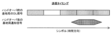
- FIG. 5 shows an example of transmission timing of the base station notification signal according to the method of the present invention.
- the base station notification signal is a signal that has continuity over three symbols, and the amplitude of the start and end of the signal is gradual, or the frequency spread of the base station notification signal is suppressed during frequency analysis by performing filter processing. And By using such a base station notification signal, it is possible to suppress deterioration of the data symbol during frequency analysis even when the propagation delay after handover is unknown.
- FIG. 6 shows an example of reception timing of the base station notification signal according to the method of the present invention.
- the base station notification signal arrives earlier than the signal from the base station before the handover 202-1.
- the base station notification signal arrives behind the signal from the base station 202-1 before the handover. To do.
- a delay difference of ⁇ half symbol length can be tolerated. Details will be described with reference to the simulation results (FIGS. 16 and 17) described later.
- FIG. 7 shows a configuration example of the mobile station side device 700 in the eigenmode MIMO transmission device.
- FIG. 9 shows a configuration example of the base station side apparatus 900 in the eigenmode MIMO transmission apparatus.
- the mobile station side device 700 of FIG. 7 corresponds to the video encoding unit 204 and mobile communication device (transmission side) 301 of the mobile station 201 of FIG. 3, and the base station side device 900 of FIG. It corresponds to the mobile communication device (reception side) 302 of the base station 202.
- the mobile station side device is simply referred to as a “mobile station”
- the base station side device is simply referred to as a “base station”.
- the mobile station 700 includes a video encoding unit 701, a buffer 702, a mobile station side transmission timing generation unit 703, a communication channel encoding unit 704, a mapping unit 705, a precoding unit 706, and an IFFT (Inverse Fast Fourier). Transform) unit 707, guard interval addition unit 708, frequency conversion unit 709, transmission/reception antenna unit 710, subframe start position detection unit 711, FFT (Fast Fourier Transform) unit 712, equalization unit 713, It includes a pilot symbol extraction unit 714, a propagation path estimation unit 715, a mapping unit 716, and a communication path decoding unit 717.
- IFFT Inverse Fast Fourier
- the base station 900 includes a transmission/reception antenna unit 901, a frequency conversion unit 902, an FFT unit 903, a subframe start position detection unit 904, a base station side transmission timing generation unit 905, an equalization unit 906, and a pilot symbol extraction.
- Unit 907 channel estimation unit 908, precoding information calculation unit 909, channel coding unit 910, 1-frame delay unit 911, demapping unit 912, channel decoding unit 913, and video decoding unit. 914, a mapping unit 915, an IFFT unit 916, a guard interval addition unit 917, and a buffer 918.
- the video coding unit 701 of the mobile station 700 performs video coding processing for reducing the amount of information of the video to be transmitted, and outputs the resulting video data signal (TS signal) to the buffer 702.
- a timing signal is also input to the buffer 702 from the transmission timing generation unit 703 on the mobile station side.
- the mobile station side transmission timing generation unit 703 has a normal frame period counter 801 as its internal configuration is shown in FIG.
- the normal frame period counter 801 is used for the UL (uplink) subframe time used for uplink communication from the mobile station 700 to the base station 900 and for downlink communication from the base station 900 to the mobile station 700.
- the timing signal is periodically output with the total time of the DL (downlink) subframe time and the guard time between each subframe.
- the buffer 702 reads the video data signal input from the video coding unit 701 according to the timing signal from the mobile station side transmission timing generation unit 703 and outputs it to the communication path coding unit 704.
- the communication path coding unit 704 performs a communication path coding process on the input signal and outputs it to the mapping unit 705.
- the mapping unit 705 maps the signal input from the channel coding unit 704 on the complex plane and outputs the signal to the precoding unit 706.
- the precoding unit 706 multiplies the data signal with the precoding information described later, does not multiply the control signal, and goes to the IFFT unit 707. Output.
- the IFFT unit 707 converts the signal input from the precoding unit 706 into a signal in the time domain, and outputs the signal to the guard interval adding unit 708.
- the guard interval addition unit 708 adds a guard interval of a preset length to the signal input from the IFFT unit 707 and outputs the signal to the frequency conversion unit 709.
- the frequency conversion unit 709 converts the signal input from the guard interval addition unit 708 into a frequency used for spatial transmission, and outputs the frequency to the transmission/reception antenna unit 710.
- the transmission / reception antenna unit 710 sends the signal input from the frequency conversion unit 709 into space.
- the signal transmitted from the mobile station 700 and propagated in space is received by the transmission/reception antenna unit 901 of the base station 900 shown in FIG. 9, and is output to the frequency conversion unit 902.
- the frequency conversion unit 902 converts the signal input from the transmission/reception antenna unit 901 into a frequency suitable for signal processing, and outputs the frequency to the FFT unit 903 and the subframe start position detection unit 904.
- the subframe start position detection unit 904 detects the start position of the subframe by performing cross-correlation calculation of the preamble signal on the signal input from the frequency conversion unit 902, and the timing indicating the start position of the subframe.
- the signal is output to the transmission timing generation unit 905 and the FFT unit 903 on the base station side.
- the FFT unit 903 performs processing for converting the signal input from the frequency conversion unit 902 into a frequency domain signal by providing an FFT window based on the timing signal input from the subframe head position detection unit 904, and The result is output to the equalization unit 906 and the pilot symbol extraction unit 907.
- the pilot symbol extraction unit 907 extracts a pilot symbol from the signal input from the FFT unit 903 and outputs it to the transmission path estimation unit 908.
- the transmission line estimation unit 908 estimates the transmission line based on the pilot symbol input from the pilot symbol extraction unit 907, and outputs the result to the equalization unit 906 and the precoding information calculation unit 909.
- the precoding information calculation unit 909 calculates precoding information based on the transmission line estimation result input from the transmission line estimation unit 908, and outputs the precoding information to the communication path coding unit 910 and the one-frame delay unit 911.
- the 1-frame delay unit 911 delays the precoding information input from the precoding information calculation unit 909 by 1 TDD frame and outputs it to the equalization unit 906.
- the 1-frame delay unit 911 is inserted because the precoding information used for precoding the received signal and the precoding information used at the time of equalization need to be in the same frame.
- the equalization unit 906 uses the frequency conversion result input from the FFT unit 903, the transmission line estimation result input from the transmission line estimation unit 908, and the precoding information input from the one-frame delay unit 911, and the like. Conversion processing and outputs the result to the demapping unit 912.
- the demapping unit 912 calculates the bit likelihood from the signal on the complex plane input from the equalization unit 906, and outputs it to the channel decoding unit 913.
- the channel decoding unit 913 decodes the video data signal based on the bit likelihood input from the demapping unit 912, and outputs the video data signal to the video decoding unit 914.
- the above is the flow of processing the UL signal transmitted from the mobile station 700 to the base station 900.
- the communication channel coding unit 910 compares the precoding information input from the precoding information calculation unit 909 with the communication channel code. Conversion processing is performed, and the result is output to the mapping unit 915.
- the mapping unit 915 maps the signal input from the channel coding unit 910 on the complex plane and outputs the signal to the IFFT unit 916.
- the IFFT unit 916 converts the signal input from the mapping unit 915 into a signal in the time domain and outputs the signal to the guard interval adding unit 917.
- the guard interval adding unit 917 adds a guard interval having a preset length to the signal input from the IFFT unit 916, and outputs the signal to the buffer 918.
- the buffer 918 reads the signal input from the guard interval addition unit 917 according to the timing signal from the base station side transmission timing generation unit 905, and outputs the signal to the frequency conversion unit 902.
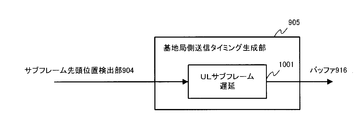
- the base station-side transmission timing generation section 905 has a UL subframe delay section 1001 as shown in the internal configuration of FIG.
- the UL subframe delay unit 1001 delays the timing signal (signal indicating the start position of the subframe) input from the subframe start position detection unit 904 by the UL subframe time and outputs it to the buffer 918. By this process, the transmission of the DL subframe can be started after the reception of the UL subframe is completed.
- the processing from the frequency conversion unit 902 to the FFT unit 712 is the same as the processing from the frequency conversion unit 709 to the FFT unit 903, which is the processing of the UL subframe, and thus a detailed description thereof will be omitted.
- the FFT unit 712 converts the signal input from the frequency conversion unit 709 into a signal in the frequency domain, and outputs the signal to the equalization unit 713 and the pilot symbol extraction unit 714.
- Pilot symbol extraction section 714 extracts a pilot symbol from the signal input from FFT section 712 and outputs it to transmission path estimation section 715.
- the transmission path estimation unit 715 performs transmission path estimation based on the pilot symbols input from the pilot symbol extraction unit 714, and outputs the result to the equalization unit 713.
- the equalization unit 713 performs equalization processing using the frequency conversion result input from the FFT unit 712 and the transmission line estimation result input from the transmission line estimation unit 715, and outputs the result to the demapping unit 716. To do.
- the demapping unit 716 calculates the bit likelihood from the signal on the complex plane input from the equalization unit 713, and outputs it to the channel decoding unit 717.
- the channel decoding unit 717 decodes the precoding information based on the bit likelihood input from the demapping unit 716, and outputs it to the precoding unit 706. The above is the flow of processing the DL signal fed back from the base station 900 to the mobile station 700.
- FIG. 11 shows a configuration example of the mobile station 700 of the eigenmode MIMO transmission apparatus compatible with handover.
- the mobile station 700 shown in FIG. 11 has a base station notification signal detection unit 1101, a handover state machine 1102, a reception state information comparison unit 1103, a precoding selection unit 1104, and control signal multiplexing in the configuration shown in FIG.
- the section 1105 is added. Further, the internal configuration of the mobile station side transmission timing generation unit 703 has been changed to the configuration shown in FIG.
- FIG. 12 shows a configuration example of the base station 900 of the unique mode MIMO transmission device corresponding to the handover.
- the base station 900 illustrated in FIG. 12 has the configuration illustrated in FIG. 9 and includes a reception state information calculation unit 1201, a threshold value determination unit 1202, a transmission gate 1203, a base station notification signal generation unit 1204, and a switching unit 1205.
- a control signal separation unit 1206 has been added. Further, the internal configuration of the base station side transmission timing generation unit 905 has been changed to the configuration shown in FIG.
- Step S101 After the handover, the base station 900-2 can receive the preamble symbol and the pilot symbol that are not precoded.
- Step S102 In the base station 900-2 after the handover, the transmission path estimation result obtained by the transmission path estimation unit 908 is output to the reception state information calculation unit 1201.
- the reception state information calculation unit 1201 calculates reception state information based on the transmission channel estimation result input from the transmission channel estimation unit 908, and outputs the reception state information to the threshold value determination unit 1202 and the communication channel coding unit 910.
- the reception state information is calculated from the transmission path estimation result, but the reception state information may be calculated based on the reception electric field, the interference power, or the like.
- the threshold determination unit 1202 determines whether the reception state information input from the reception state information calculation unit 1201 exceeds a preset threshold value (Th1), and outputs the threshold determination result to the transmission gate 1203. Specifically, the threshold value determination unit 1202 outputs a signal for opening the transmission gate 1203 when the reception state information exceeds the threshold value.
- the communication path coding unit 910 encodes the reception status information in addition to the precoding information and outputs it to the mapping unit 915.
- the transmission gate 1203 outputs a signal to the switching unit 1205 according to the threshold determination result input from the threshold determination unit 1202 in order to transmit the base station notification signal input from the base station notification signal generation unit 1204.
- the switching unit 1205 is a signal for transmitting the reception state information and the precoding information calculated by the reception state information calculation unit 1201 and the precoding information calculation unit 909 to the mobile station 700 (hereinafter, referred to as “feedback information”). Is also input from the guard interval addition unit 917.
- the switching unit 1205 selects a signal to be transmitted to the mobile station 700 based on the signal input from the control signal separation unit 1206 newly added between the FFT unit 903 and the equalization unit 906, and outputs the signal to the buffer 918. To do. Although details will be described later, state information indicating whether the mobile station 700 is in the normal state (T1501) or the handover state (T1502) and the precoding information used by the mobile station 700 for precoding by the control signal from the mobile station 700. The base station ID that identifies the source base station of the above is notified. The switching unit 1205 selects the transmission of the base station notification signal when the state information is in the normal state and the base station ID is other than the own station, and selects the transmission of the feedback information in other cases.
- the base station notification signal needs to be transmitted so as not to interfere with the communication between the base station 900-1 and the mobile station 700 before the handover. Therefore, the base station transmission timing generation section 905 is changed to the configuration shown in FIG. 14, and the signal from the control signal separation section 1206 is newly input.
- the base station transmission timing generation unit 905 branches the timing signal (signal indicating the start position of the subframe) input from the subframe head position detection unit 904 into three delay units 1401 to 1403, and any of the delay units The delayed timing signal is selected by the selection unit 1404 and output to the buffer 918.
- the three delay units 1401 to 1403 will be described below.
- the UL subframe delay unit 1401 having a delay of the UL subframe is used when it is necessary to start transmission after the UL subframe is completely received. That is, it is used when the mobile station 700 and the base station 900 are communicating one-to-one, and when the mobile station 700 and two base stations 900 are communicating and the precoding information of the own station is selected.
- the UL subframe+DL subframe delay unit 1402 having a delay corresponding to the UL subframe and the DL subframe is used when another station needs to start the transmission after completing the transmission of the DL subframe. That is, it is used when the mobile station 700 and two base stations 900 communicate with each other and precoding information of another station is selected.
- the base station notification signal delay unit 1403 having a delay of UL subframe, preamble length, pilot symbol length, and half symbol length is used when transmitting a base station notification signal.
- the selection of the delay units 1401 to 1403 by the selection unit 1404 is performed by the following logic.
- the selection unit 1404 selects the UL subframe delay unit 1401 when the base station ID is its own station, and when the base station ID is other than its own station and is in the handover state (T1502), the UL subframe + DL subframe delay unit 1402 Otherwise, the base station notification signal delay unit 1403 is selected.
- the base station 900 after the handover selects the signal delayed by the base station notification signal delay unit 1403 because the base station ID of the control signal is other than the own station and is not in the handover state.
- the base station notification signal is transmitted at the base station notification signal reception timing of the TDD frame.
- Step S104 In the mobile station 700, the base station notification signal notified from the base station 900-2 after the handover is input to the base station notification signal detection unit 1101 via the FFT unit 712 and detected.
- Step S105 The base station notification signal detection unit 1101 notifies the handover state machine 1102 that the base station notification signal has been detected.
- FIG. 15 shows the state transition of the handover state machine 1102.
- the handover state machine 1102 is in the normal state (T1501) when the mobile station 700 and the base station 900 are communicating one-to-one, and is in the handover state (T1502) when the base station notification signal is continuously received.
- the reception state of the base station 900-1 before the handover is lower than the preset threshold (Th3) as compared with the reception state of the base station 900-2 after the handover, the transition to the normal state (T1501) occurs.
- Th3 preset threshold
- step S305 the base station notification signal is continuously received, and the handover state machine 1102 moves from the normal state (T1501) to the handover state (T1502) and moves the signal (state information) notifying that it is in the handover state. It is output to the station side transmission timing generation unit 703 and the control signal multiplexing unit 1105.
- the transition to the handover state is preferably performed when the base station notification signal is continuously received a plurality of times as in this example, but the transition to the handover state may be made when the base station notification signal is received once. Good.
- the control signal multiplexing unit 1105 multiplexes the base station ID input from the reception state information comparison unit 1103 and the state information input from the handover state machine 1102, which will be described later, with the control signal of the UL subframe and notifies the base station 900. To do. Note that the control signal is transmitted omnidirectionally without precoding, so that it can be received by either the base station 900-1 before the handover or the base station 900-2 after the handover if a sufficient reception electric field can be secured. is there.
- the timing signal of the normal frame period counter 801 and the timing signal of the handover frame period counter 1302 are input to the selection unit 1301 of the mobile station side transmission timing generation unit 703.
- the selection unit 1301 selects the timing signal of the normal frame cycle counter 801 when the handover state machine 1102 is in the normal state (T1501), and selects the timing signal of the handover frame cycle counter 1302 when the handover state machine 1102 is in the handover state (T1502).
- TDD frame cycle in which the time domain for receiving the DL signal from the base station 900-2 after the handover is added.
- Step S106 When the base station 900-2 after the handover receives the UL signal in which the state information and the base station ID are multiplexed, the control signal separation unit 904 separates the state information and the base station ID.
- Step S107 The state information and the base station ID notified from the mobile station 700 are output to the switching unit 1205 and the base station side transmission timing generation unit 905.
- the switching unit 1205 selects the feedback information (precoding information and reception state information) input from the guard interval addition unit 915 and outputs the feedback information (precoding information and reception state information) to the buffer 918.
- the base station side transmission timing generation unit 905 is in the case where the base station ID is other than its own station and is in the handover state, so that the output signal of the UL subframe + DL subframe delay unit 1402 is selected. R.
- the DL subframe can be transmitted from the base station 900-2 after the handover after the DL subframe transmitted from the base station 900-1 before the handover.
- Step S108 The mobile station 700 receives the feedback information from each of the base station 900-1 before the handover and the base station 900-2 after the handover, and the communication channel decoding unit 710 decodes the feedback information.
- the communication path decoding unit 710 outputs the precoding information from the two decoded base stations 900 to the precoding selection unit 1104, and outputs the reception status information from the two decoded base stations 900 to the reception status information comparison unit 1103. To do.
- the reception state information comparison unit 1103 compares the reception state information from the base station 900-1 before the handover with the reception state information from the base station 900-2 after the handover, and determines whether the reception state information is equal to or more than a preset threshold value (Th2). When the reception state after the handover is good, a signal for selecting the precoding information from the base station 900-2 after the handover is output to the precoding selection unit 1104.
- the precoding selection unit 1104 selects precoding information from the base station 900-2 after handover and outputs it to the precoding unit 706 based on the reception state comparison result input from the reception state information comparison unit 1103. ..
- Step S110 The precoding unit 706 performs precoding using the precoding information from the base station 900-2 after the handover. As a result, the data signal from the mobile station 700 is transmitted to the base station 900-2 after the handover.
- the reception status information comparison unit 1103 compares the reception status information from the base station 900-1 before the handover with the reception status information from the base station 900-2 after the handover, and determines whether the reception status information is equal to or more than a preset threshold value (Th3).
- Th3 a preset threshold value
- Step S112 The state of the handover state machine 1102 transitions to the normal state (T1501), and the mobile station side transmission timing generation unit 703 switches to the timing signal of the normal frame cycle counter 801. As a result, the time domain for communicating with the base station 900-1 before the handover is deleted from the TDD frame cycle. Also, since the transmission gate 1203 is closed in response to the deterioration of the reception state of the base station 900-1 before the handover and no signal is output to the switching unit 1205, the base station notification transmission from the base station 900-1 before the handover is performed. Will be stopped.
- a frame consisting of a preamble symbol, a pilot symbol, and three data symbols is transmitted from the base station before the handover, and the base station after the handover inserts a base station notification signal into the data symbol portion and transmits the frame.
- the base station notification signal for three symbols is inserted as it is is defined as "no countermeasure”
- the case where the base station notification signal is inserted with a gentle rise and fall is defined as "with countermeasure”.
- FIG. 16 is a diagram showing a signal waveform when the base station notification signal arrives 12.5 ⁇ s earlier due to the influence of transmission delay. From top to bottom, the signal waveform of the transmission signal from the base station before the handover, the signal waveform when the base station notification signal (without countermeasure) arrives 12.5 ⁇ s earlier, and the base station notification signal (with countermeasure) 12.5 ⁇ s earlier The signal waveform when reaching is illustrated.
- FIG. 17 is a diagram showing the effect when the base station notification signal arrives 12.5 ⁇ s earlier due to the effect of transmission delay. From top to bottom, for each of the pilot symbol, the first data symbol, the second data symbol, and the third data symbol, the SIR (Signal to Interference Radio) of the subcarrier of each symbol in the DL signal from the base station before the handover is ; Signal power to interference power ratio) is illustrated.
- “ ⁇ ” in the graph is the SIR in the case of “without countermeasure”
- “x” is the SIR in the case of “with countermeasure”.
- the area with the background color represents the data subcarrier area (corresponding to the data subcarrier on the right side of FIG. 4).
- the base station notification signal (with countermeasures), as shown in the graph in the third row of FIG. 16, the base station notification signal has not yet risen in the area of the pilot symbol, and there is no interference with the pilot symbol. .. Further, as shown by "x" in the first graph of FIG. 17, SIR is not deteriorated.
- the base station notification signal In the case of the base station notification signal (no countermeasure), as shown in the second graph of FIG. 16, the base station notification signal continuously interferes with the first data symbol at a constant amplitude. However, as shown by “ ⁇ ” in the second graph of FIG. 17, the interference component is concentrated in one subcarrier outside the data subcarrier region, and there is no interference with the data subcarrier region.
- the base station notification signal gently rises and interferes in the area of the first data symbol, as shown in the third graph in FIG. As indicated by “x” in the second graph of FIG. 17, the interference component spreads smoothly, but an SIR of 35 dB or more is obtained even at the edge (outermost side) of the data subcarrier area.
- the base station notification signal (with countermeasures)
- the base station notification signal slightly interferes with the first half of the area of the third data symbol.
- the interference component slightly spreads, but there is almost no interference at the end of the data subcarrier area.
- the mobile station 700 has the second base station 900 different from the first base station 900-1 (202-1) that is the current communication partner.
- -2 (202-2) can become a new communication partner, a transmission timing different from the transmission timing of the reception status information and the precoding information by the first base station 900-1 is set to the second base station 900-2.
- the second base station 900-2 transmits the reception status information and the precoding information of its own station at the transmission timing notified from the mobile station 700, and the mobile station 700 transmits the first base station 900.
- the reception status information received from the second base station 900-2 are compared, and the reception status of the second base station 900-2 is compared with the reception status of the first base station 900-1 in advance.
- the communication partner is switched to the second base station 900-2, and the precoding information received from the second base station 900-2 is applied to apply the second base station 900-2. -2 to send data.
- the mobile station 700 performs the handover without affecting the communication with the base station 900-1 of the current communication partner. Can determine the need for.
- the mobile station 700 can also obtain the precoding information of the base station 900-2 after the handover in advance, and thus can quickly execute the handover when it is determined that the handover is necessary. Therefore, it is possible to prevent an instantaneous transmission error when performing a handover.
- the mobile station 700 transmits an omnidirectional control signal to which the precoding information is not applied, separately from the data signal to which the precoding information is applied, and the first base station 900-1
- the second base station 900-2 and the second base station 900-2 each measure the reception state of the control signal and generate the reception state information. Therefore, even the base station 900-2, which is not the current communication partner, can receive the control signal and measure the reception state.
- the second base station 900-2 transmits the base station notification signal for notifying the presence of its own station to the mobile station when the reception state of the control signal is equal to or higher than the preset threshold value.
- the mobile station 700 receives the base station notification signal from the second base station 900-2, the mobile station 700 notifies the second base station 900-2 of the transmission timing of the reception state information and the precoding information. It may be configured to. Therefore, the base station 900-2, which is not the current communication partner, can make the mobile station 700 recognize that it can become a new communication partner, and obtain the reception status information and the transmission timing of the precoding information of the mobile station 700. Become.
- the frame used for data transmission from the first base station 900-1 to the mobile station 700 includes a preamble symbol, a pilot symbol, and a plurality of data symbols.
- the base station 900-2 transmits the base station notification signal using the NULL carriers on both sides of each of the plurality of data symbols in the frequency direction. Therefore, the influence of the base station notification signal on the DL signal of the first base station 900-1 can be reduced. It should be noted that there are a plurality of NULL carriers on both sides in the frequency direction of the data symbol, and any NULL carrier may be used for transmitting the base station notification signal, but it is better to use the outermost NULL carrier as the first carrier. It is preferable because the influence on the DL signal of the base station 900-1 can be minimized.
- the base station notification signal has a gentle rising and falling signal waveform. Therefore, the frequency spread of the base station notification signal is suppressed during the frequency analysis when the mobile station 700 performs the frequency analysis of the DL signal of the first base station 900-1, and the interference of the base station notification signal with the DL signal is reduced. be able to. Further, even when the propagation delay after handover is unknown, deterioration of the data symbol can be suppressed during frequency analysis.
- the case where there are two base stations has been described as an example, but there may be three or more base stations with which the mobile station can communicate.
- a method in which a base station that can be a new communication partner multiplexes its own base station ID with a base station notification signal a method in which a subcarrier that transmits a base station notification signal is changed for each base station, and the like. This allows the mobile station to identify the source of the base station notification signal, selects the base station to be handed over by the mobile station, and notifies each base station whether or not the feedback information (reception status information and precoding information) can be transmitted. ..
- the present invention has been described in detail above, it goes without saying that the present invention is not limited to the wireless communication systems described here, and can be widely applied to wireless communication systems other than the above. Further, the present invention can also be grasped as a transmitting station or a receiving station constituting the above-mentioned wireless communication system.
- the present invention can also be provided as, for example, a method or method for executing the process according to the present invention, a program for realizing such a method or method, a storage medium storing the program, or the like.
- the present invention can be used in a wireless communication system in which a mobile station applies precoding information received from a base station to transmit data to the base station.
- 201 mobile station, 202: base station, 203: aggregation station, 204: video encoding unit, 205: mobile communication device (transmission side), 206: mobile communication device (reception side), 207: fixed communication device (transmission side) ), 208: fixed communication device (reception side), 209: TS selection device, 210: video decoding unit, 301: mobile communication device (transmission side), 302: mobile communication device (reception side), 700: mobile station side Device, 701: video coding unit, 702: buffer, 703: mobile station side transmission timing generation unit, 704: channel coding unit, 705: mapping unit, 706: precoding unit, 707: IFFT unit, 708: guard Interval addition unit, 709: frequency conversion unit, 710: transmission/reception antenna unit, 711: subframe start position detection unit, 712: FFT unit, 713: equalization unit, 714: pilot symbol extraction unit, 715: propagation path estimation unit, 716: Mapping unit, 717: Channel decoding unit
Landscapes
- Engineering & Computer Science (AREA)
- Computer Networks & Wireless Communication (AREA)
- Signal Processing (AREA)
- Mobile Radio Communication Systems (AREA)
Abstract
Le problème décrit par la présente invention est de fournir un système de communication sans fil susceptible d'empêcher une erreur de transmission instantanée lors de la réalisation d'un transfert intercellulaire. Dans la solution de l'invention, lorsqu'une seconde station de base (202-2) différente d'une première station de base (202-1) constituant le partenaire de communication en cours peut constituer un nouveau partenaire de communication, la station mobile (201) notifie à la seconde station de base une synchronisation de transmission différente de la synchronisation de transmission d'informations d'état de réception et d'informations de précodage par la première station de base. La seconde station de base transmet ses propres informations d'état de réception et informations de précodage à la synchronisation de transmission notifiée par la station mobile. La station mobile compare les informations d'état de réception reçues en provenance de la première station de base et de la seconde station de base, et lorsque l'état de réception de la seconde station de base est supérieur à la valeur seuil prédéfinie par comparaison avec l'état de réception de la première station de base, commute le partenaire de communication vers la seconde station de base, et applique les informations de précodage reçues en provenance de la seconde station de base pour transmettre des données à la seconde station de base.
Priority Applications (1)
| Application Number | Priority Date | Filing Date | Title |
|---|---|---|---|
| JP2021503441A JP7000628B2 (ja) | 2019-03-04 | 2020-01-14 | 無線通信システム、基地局及び移動局 |
Applications Claiming Priority (2)
| Application Number | Priority Date | Filing Date | Title |
|---|---|---|---|
| JP2019038512 | 2019-03-04 | ||
| JP2019-038512 | 2019-03-04 |
Publications (1)
| Publication Number | Publication Date |
|---|---|
| WO2020179227A1 true WO2020179227A1 (fr) | 2020-09-10 |
Family
ID=72337488
Family Applications (1)
| Application Number | Title | Priority Date | Filing Date |
|---|---|---|---|
| PCT/JP2020/000893 Ceased WO2020179227A1 (fr) | 2019-03-04 | 2020-01-14 | Système de communication sans fil, station de base et station mobile |
Country Status (2)
| Country | Link |
|---|---|
| JP (1) | JP7000628B2 (fr) |
| WO (1) | WO2020179227A1 (fr) |
Citations (1)
| Publication number | Priority date | Publication date | Assignee | Title |
|---|---|---|---|---|
| JP2014072778A (ja) * | 2012-09-28 | 2014-04-21 | Ntt Docomo Inc | 無線通信システム、基地局装置、ユーザ端末及び無線通信方法 |
-
2020
- 2020-01-14 WO PCT/JP2020/000893 patent/WO2020179227A1/fr not_active Ceased
- 2020-01-14 JP JP2021503441A patent/JP7000628B2/ja active Active
Patent Citations (1)
| Publication number | Priority date | Publication date | Assignee | Title |
|---|---|---|---|---|
| JP2014072778A (ja) * | 2012-09-28 | 2014-04-21 | Ntt Docomo Inc | 無線通信システム、基地局装置、ユーザ端末及び無線通信方法 |
Also Published As
| Publication number | Publication date |
|---|---|
| JP7000628B2 (ja) | 2022-01-19 |
| JPWO2020179227A1 (ja) | 2021-11-04 |
Similar Documents
| Publication | Publication Date | Title |
|---|---|---|
| US8331476B2 (en) | Method for detecting transmission mode in a system using multiple antennas | |
| US9723508B2 (en) | Wireless interference mitigation | |
| US8238307B2 (en) | Method and device for canceling the interference among signals received by multiple mobile stations | |
| KR102282007B1 (ko) | 무선통신 시스템에서 간섭 신호 제거 및 억제를 통한 하향 링크 데이터 수신 방법 및 장치 | |
| US10476621B2 (en) | Methods and arrangements for mitigating inter-cluster interference | |
| US10020927B2 (en) | Method and device for decoding reception signal in wireless communication system | |
| KR102244366B1 (ko) | 무선통신 시스템에서 간섭 신호 제거 및 억제를 위한 무선 자원 활용 방법 및 장치 | |
| US8494077B2 (en) | Method and communication system for transmitting data in a multiple-input multiple-output (MIMO) system | |
| US20150003343A1 (en) | Network assisted interference mitigation | |
| KR20150107490A (ko) | 무선통신 시스템에서 간섭 신호 제거 및 억제를 위한 제어정보 전송 방법 및 장치 | |
| US11411621B2 (en) | Uplink and downlink reciprocity management of interference | |
| CN104885393A (zh) | 自适应传送模式切换 | |
| EP2544420A1 (fr) | Procédé de transmission de données dans un système de communication, premier noeud de réseau et deuxième noeud de réseau correspondants | |
| KR101754990B1 (ko) | 통신 시스템에서의 협력 통신 방법 및 장치 | |
| US9860019B2 (en) | Base station apparatus, wireless communication system, and communication method | |
| JP7000628B2 (ja) | 無線通信システム、基地局及び移動局 | |
| TW201304448A (zh) | 通訊系統中傳輸資料之方法及其第一網路節點及第二網路節點 | |
| CN121153233A (zh) | 用于动态预均衡切换的技术 | |
| KR101694066B1 (ko) | 프리 코딩을 통한 협력 통신 시스템 및 그것을 이용한 협력 통신 방법 | |
| US10111234B2 (en) | Frequency assignment method and transmission apparatus therefor | |
| KR101694065B1 (ko) | 인접 기지국을 활용하는 협력 통신 시스템 및 그것을 이용한 협력 통신 방법 | |
| US10219294B2 (en) | Data transmission on a contention based physical data channel | |
| US20250189650A1 (en) | Dedicated receiver components for mono-sensing procedures | |
| Mikami et al. | An inter-cell interference cancellation scheme with multi-cell coordinated scheduling for downlink of MIMO/OFDM cellular systems | |
| Chang et al. | Interference suppression for railway radio-over-fiber communication systems |
Legal Events
| Date | Code | Title | Description |
|---|---|---|---|
| 121 | Ep: the epo has been informed by wipo that ep was designated in this application |
Ref document number: 20766132 Country of ref document: EP Kind code of ref document: A1 |
|
| ENP | Entry into the national phase |
Ref document number: 2021503441 Country of ref document: JP Kind code of ref document: A |
|
| NENP | Non-entry into the national phase |
Ref country code: DE |
|
| 122 | Ep: pct application non-entry in european phase |
Ref document number: 20766132 Country of ref document: EP Kind code of ref document: A1 |