WO2020179595A1 - Composition de graisse - Google Patents
Composition de graisse Download PDFInfo
- Publication number
- WO2020179595A1 WO2020179595A1 PCT/JP2020/007937 JP2020007937W WO2020179595A1 WO 2020179595 A1 WO2020179595 A1 WO 2020179595A1 JP 2020007937 W JP2020007937 W JP 2020007937W WO 2020179595 A1 WO2020179595 A1 WO 2020179595A1
- Authority
- WO
- WIPO (PCT)
- Prior art keywords
- grease
- grease composition
- extreme pressure
- urea
- pressure agent
- Prior art date
- Legal status (The legal status is an assumption and is not a legal conclusion. Google has not performed a legal analysis and makes no representation as to the accuracy of the status listed.)
- Ceased
Links
Images


Classifications
-
- C—CHEMISTRY; METALLURGY
- C10—PETROLEUM, GAS OR COKE INDUSTRIES; TECHNICAL GASES CONTAINING CARBON MONOXIDE; FUELS; LUBRICANTS; PEAT
- C10M—LUBRICATING COMPOSITIONS; USE OF CHEMICAL SUBSTANCES EITHER ALONE OR AS LUBRICATING INGREDIENTS IN A LUBRICATING COMPOSITION
- C10M171/00—Lubricating compositions characterised by purely physical criteria, e.g. containing as base-material, thickener or additive, ingredients which are characterised exclusively by their numerically specified physical properties, i.e. containing ingredients which are physically well-defined but for which the chemical nature is either unspecified or only very vaguely indicated
- C10M171/06—Particles of special shape or size
-
- C—CHEMISTRY; METALLURGY
- C10—PETROLEUM, GAS OR COKE INDUSTRIES; TECHNICAL GASES CONTAINING CARBON MONOXIDE; FUELS; LUBRICANTS; PEAT
- C10M—LUBRICATING COMPOSITIONS; USE OF CHEMICAL SUBSTANCES EITHER ALONE OR AS LUBRICATING INGREDIENTS IN A LUBRICATING COMPOSITION
- C10M169/00—Lubricating compositions characterised by containing as components a mixture of at least two types of ingredient selected from base-materials, thickeners or additives, covered by the preceding groups, each of these compounds being essential
-
- C—CHEMISTRY; METALLURGY
- C10—PETROLEUM, GAS OR COKE INDUSTRIES; TECHNICAL GASES CONTAINING CARBON MONOXIDE; FUELS; LUBRICANTS; PEAT
- C10M—LUBRICATING COMPOSITIONS; USE OF CHEMICAL SUBSTANCES EITHER ALONE OR AS LUBRICATING INGREDIENTS IN A LUBRICATING COMPOSITION
- C10M101/00—Lubricating compositions characterised by the base-material being a mineral or fatty oil
- C10M101/02—Petroleum fractions
-
- C—CHEMISTRY; METALLURGY
- C10—PETROLEUM, GAS OR COKE INDUSTRIES; TECHNICAL GASES CONTAINING CARBON MONOXIDE; FUELS; LUBRICANTS; PEAT
- C10M—LUBRICATING COMPOSITIONS; USE OF CHEMICAL SUBSTANCES EITHER ALONE OR AS LUBRICATING INGREDIENTS IN A LUBRICATING COMPOSITION
- C10M107/00—Lubricating compositions characterised by the base-material being a macromolecular compound
- C10M107/02—Hydrocarbon polymers; Hydrocarbon polymers modified by oxidation
-
- C—CHEMISTRY; METALLURGY
- C10—PETROLEUM, GAS OR COKE INDUSTRIES; TECHNICAL GASES CONTAINING CARBON MONOXIDE; FUELS; LUBRICANTS; PEAT
- C10M—LUBRICATING COMPOSITIONS; USE OF CHEMICAL SUBSTANCES EITHER ALONE OR AS LUBRICATING INGREDIENTS IN A LUBRICATING COMPOSITION
- C10M115/00—Lubricating compositions characterised by the thickener being a non-macromolecular organic compound other than a carboxylic acid or salt thereof
- C10M115/08—Lubricating compositions characterised by the thickener being a non-macromolecular organic compound other than a carboxylic acid or salt thereof containing nitrogen
-
- C—CHEMISTRY; METALLURGY
- C10—PETROLEUM, GAS OR COKE INDUSTRIES; TECHNICAL GASES CONTAINING CARBON MONOXIDE; FUELS; LUBRICANTS; PEAT
- C10M—LUBRICATING COMPOSITIONS; USE OF CHEMICAL SUBSTANCES EITHER ALONE OR AS LUBRICATING INGREDIENTS IN A LUBRICATING COMPOSITION
- C10M129/00—Lubricating compositions characterised by the additive being an organic non-macromolecular compound containing oxygen
- C10M129/02—Lubricating compositions characterised by the additive being an organic non-macromolecular compound containing oxygen having a carbon chain of less than 30 atoms
- C10M129/26—Carboxylic acids; Salts thereof
- C10M129/28—Carboxylic acids; Salts thereof having carboxyl groups bound to acyclic or cycloaliphatic carbon atoms
- C10M129/38—Carboxylic acids; Salts thereof having carboxyl groups bound to acyclic or cycloaliphatic carbon atoms having 8 or more carbon atoms
- C10M129/40—Carboxylic acids; Salts thereof having carboxyl groups bound to acyclic or cycloaliphatic carbon atoms having 8 or more carbon atoms monocarboxylic
-
- C—CHEMISTRY; METALLURGY
- C10—PETROLEUM, GAS OR COKE INDUSTRIES; TECHNICAL GASES CONTAINING CARBON MONOXIDE; FUELS; LUBRICANTS; PEAT
- C10M—LUBRICATING COMPOSITIONS; USE OF CHEMICAL SUBSTANCES EITHER ALONE OR AS LUBRICATING INGREDIENTS IN A LUBRICATING COMPOSITION
- C10M133/00—Lubricating compositions characterised by the additive being an organic non-macromolecular compound containing nitrogen
- C10M133/02—Lubricating compositions characterised by the additive being an organic non-macromolecular compound containing nitrogen having a carbon chain of less than 30 atoms
- C10M133/04—Amines, e.g. polyalkylene polyamines; Quaternary amines
- C10M133/12—Amines, e.g. polyalkylene polyamines; Quaternary amines having amino groups bound to a carbon atom of a six-membered aromatic ring
-
- C—CHEMISTRY; METALLURGY
- C10—PETROLEUM, GAS OR COKE INDUSTRIES; TECHNICAL GASES CONTAINING CARBON MONOXIDE; FUELS; LUBRICANTS; PEAT
- C10M—LUBRICATING COMPOSITIONS; USE OF CHEMICAL SUBSTANCES EITHER ALONE OR AS LUBRICATING INGREDIENTS IN A LUBRICATING COMPOSITION
- C10M135/00—Lubricating compositions characterised by the additive being an organic non-macromolecular compound containing sulfur, selenium or tellurium
- C10M135/08—Lubricating compositions characterised by the additive being an organic non-macromolecular compound containing sulfur, selenium or tellurium containing a sulfur-to-oxygen bond
- C10M135/10—Sulfonic acids or derivatives thereof
-
- C—CHEMISTRY; METALLURGY
- C10—PETROLEUM, GAS OR COKE INDUSTRIES; TECHNICAL GASES CONTAINING CARBON MONOXIDE; FUELS; LUBRICANTS; PEAT
- C10M—LUBRICATING COMPOSITIONS; USE OF CHEMICAL SUBSTANCES EITHER ALONE OR AS LUBRICATING INGREDIENTS IN A LUBRICATING COMPOSITION
- C10M135/00—Lubricating compositions characterised by the additive being an organic non-macromolecular compound containing sulfur, selenium or tellurium
- C10M135/12—Thio-acids; Thiocyanates; Derivatives thereof
- C10M135/14—Thio-acids; Thiocyanates; Derivatives thereof having a carbon-to-sulfur double bond
- C10M135/18—Thio-acids; Thiocyanates; Derivatives thereof having a carbon-to-sulfur double bond thiocarbamic type, e.g. containing the groups
-
- C—CHEMISTRY; METALLURGY
- C10—PETROLEUM, GAS OR COKE INDUSTRIES; TECHNICAL GASES CONTAINING CARBON MONOXIDE; FUELS; LUBRICANTS; PEAT
- C10M—LUBRICATING COMPOSITIONS; USE OF CHEMICAL SUBSTANCES EITHER ALONE OR AS LUBRICATING INGREDIENTS IN A LUBRICATING COMPOSITION
- C10M137/00—Lubricating compositions characterised by the additive being an organic non-macromolecular compound containing phosphorus
- C10M137/02—Lubricating compositions characterised by the additive being an organic non-macromolecular compound containing phosphorus having no phosphorus-to-carbon bond
- C10M137/04—Phosphate esters
- C10M137/08—Ammonium or amine salts
-
- C—CHEMISTRY; METALLURGY
- C10—PETROLEUM, GAS OR COKE INDUSTRIES; TECHNICAL GASES CONTAINING CARBON MONOXIDE; FUELS; LUBRICANTS; PEAT
- C10M—LUBRICATING COMPOSITIONS; USE OF CHEMICAL SUBSTANCES EITHER ALONE OR AS LUBRICATING INGREDIENTS IN A LUBRICATING COMPOSITION
- C10M137/00—Lubricating compositions characterised by the additive being an organic non-macromolecular compound containing phosphorus
- C10M137/02—Lubricating compositions characterised by the additive being an organic non-macromolecular compound containing phosphorus having no phosphorus-to-carbon bond
- C10M137/04—Phosphate esters
- C10M137/10—Thio derivatives
- C10M137/105—Thio derivatives not containing metal
-
- C—CHEMISTRY; METALLURGY
- C10—PETROLEUM, GAS OR COKE INDUSTRIES; TECHNICAL GASES CONTAINING CARBON MONOXIDE; FUELS; LUBRICANTS; PEAT
- C10M—LUBRICATING COMPOSITIONS; USE OF CHEMICAL SUBSTANCES EITHER ALONE OR AS LUBRICATING INGREDIENTS IN A LUBRICATING COMPOSITION
- C10M141/00—Lubricating compositions characterised by the additive being a mixture of two or more compounds covered by more than one of the main groups C10M125/00 - C10M139/00, each of these compounds being essential
- C10M141/10—Lubricating compositions characterised by the additive being a mixture of two or more compounds covered by more than one of the main groups C10M125/00 - C10M139/00, each of these compounds being essential at least one of them being an organic phosphorus-containing compound
-
- C—CHEMISTRY; METALLURGY
- C10—PETROLEUM, GAS OR COKE INDUSTRIES; TECHNICAL GASES CONTAINING CARBON MONOXIDE; FUELS; LUBRICANTS; PEAT
- C10M—LUBRICATING COMPOSITIONS; USE OF CHEMICAL SUBSTANCES EITHER ALONE OR AS LUBRICATING INGREDIENTS IN A LUBRICATING COMPOSITION
- C10M159/00—Lubricating compositions characterised by the additive being of unknown or incompletely defined constitution
- C10M159/12—Reaction products
-
- F—MECHANICAL ENGINEERING; LIGHTING; HEATING; WEAPONS; BLASTING
- F16—ENGINEERING ELEMENTS AND UNITS; GENERAL MEASURES FOR PRODUCING AND MAINTAINING EFFECTIVE FUNCTIONING OF MACHINES OR INSTALLATIONS; THERMAL INSULATION IN GENERAL
- F16H—GEARING
- F16H57/00—General details of gearing
- F16H57/04—Features relating to lubrication or cooling or heating
- F16H57/0463—Grease lubrication; Drop-feed lubrication
- F16H57/0464—Grease lubrication
-
- C—CHEMISTRY; METALLURGY
- C10—PETROLEUM, GAS OR COKE INDUSTRIES; TECHNICAL GASES CONTAINING CARBON MONOXIDE; FUELS; LUBRICANTS; PEAT
- C10M—LUBRICATING COMPOSITIONS; USE OF CHEMICAL SUBSTANCES EITHER ALONE OR AS LUBRICATING INGREDIENTS IN A LUBRICATING COMPOSITION
- C10M2203/00—Organic non-macromolecular hydrocarbon compounds and hydrocarbon fractions as ingredients in lubricant compositions
- C10M2203/10—Petroleum or coal fractions, e.g. tars, solvents, bitumen
- C10M2203/1006—Petroleum or coal fractions, e.g. tars, solvents, bitumen used as base material
-
- C—CHEMISTRY; METALLURGY
- C10—PETROLEUM, GAS OR COKE INDUSTRIES; TECHNICAL GASES CONTAINING CARBON MONOXIDE; FUELS; LUBRICANTS; PEAT
- C10M—LUBRICATING COMPOSITIONS; USE OF CHEMICAL SUBSTANCES EITHER ALONE OR AS LUBRICATING INGREDIENTS IN A LUBRICATING COMPOSITION
- C10M2203/00—Organic non-macromolecular hydrocarbon compounds and hydrocarbon fractions as ingredients in lubricant compositions
- C10M2203/10—Petroleum or coal fractions, e.g. tars, solvents, bitumen
- C10M2203/102—Aliphatic fractions
- C10M2203/1025—Aliphatic fractions used as base material
-
- C—CHEMISTRY; METALLURGY
- C10—PETROLEUM, GAS OR COKE INDUSTRIES; TECHNICAL GASES CONTAINING CARBON MONOXIDE; FUELS; LUBRICANTS; PEAT
- C10M—LUBRICATING COMPOSITIONS; USE OF CHEMICAL SUBSTANCES EITHER ALONE OR AS LUBRICATING INGREDIENTS IN A LUBRICATING COMPOSITION
- C10M2203/00—Organic non-macromolecular hydrocarbon compounds and hydrocarbon fractions as ingredients in lubricant compositions
- C10M2203/10—Petroleum or coal fractions, e.g. tars, solvents, bitumen
- C10M2203/104—Aromatic fractions
- C10M2203/1045—Aromatic fractions used as base material
-
- C—CHEMISTRY; METALLURGY
- C10—PETROLEUM, GAS OR COKE INDUSTRIES; TECHNICAL GASES CONTAINING CARBON MONOXIDE; FUELS; LUBRICANTS; PEAT
- C10M—LUBRICATING COMPOSITIONS; USE OF CHEMICAL SUBSTANCES EITHER ALONE OR AS LUBRICATING INGREDIENTS IN A LUBRICATING COMPOSITION
- C10M2205/00—Organic macromolecular hydrocarbon compounds or fractions, whether or not modified by oxidation as ingredients in lubricant compositions
- C10M2205/02—Organic macromolecular hydrocarbon compounds or fractions, whether or not modified by oxidation as ingredients in lubricant compositions containing acyclic monomers
- C10M2205/0206—Organic macromolecular hydrocarbon compounds or fractions, whether or not modified by oxidation as ingredients in lubricant compositions containing acyclic monomers used as base material
-
- C—CHEMISTRY; METALLURGY
- C10—PETROLEUM, GAS OR COKE INDUSTRIES; TECHNICAL GASES CONTAINING CARBON MONOXIDE; FUELS; LUBRICANTS; PEAT
- C10M—LUBRICATING COMPOSITIONS; USE OF CHEMICAL SUBSTANCES EITHER ALONE OR AS LUBRICATING INGREDIENTS IN A LUBRICATING COMPOSITION
- C10M2205/00—Organic macromolecular hydrocarbon compounds or fractions, whether or not modified by oxidation as ingredients in lubricant compositions
- C10M2205/02—Organic macromolecular hydrocarbon compounds or fractions, whether or not modified by oxidation as ingredients in lubricant compositions containing acyclic monomers
- C10M2205/028—Organic macromolecular hydrocarbon compounds or fractions, whether or not modified by oxidation as ingredients in lubricant compositions containing acyclic monomers containing aliphatic monomers having more than four carbon atoms
- C10M2205/0285—Organic macromolecular hydrocarbon compounds or fractions, whether or not modified by oxidation as ingredients in lubricant compositions containing acyclic monomers containing aliphatic monomers having more than four carbon atoms used as base material
-
- C—CHEMISTRY; METALLURGY
- C10—PETROLEUM, GAS OR COKE INDUSTRIES; TECHNICAL GASES CONTAINING CARBON MONOXIDE; FUELS; LUBRICANTS; PEAT
- C10M—LUBRICATING COMPOSITIONS; USE OF CHEMICAL SUBSTANCES EITHER ALONE OR AS LUBRICATING INGREDIENTS IN A LUBRICATING COMPOSITION
- C10M2207/00—Organic non-macromolecular hydrocarbon compounds containing hydrogen, carbon and oxygen as ingredients in lubricant compositions
- C10M2207/10—Carboxylix acids; Neutral salts thereof
- C10M2207/12—Carboxylix acids; Neutral salts thereof having carboxyl groups bound to acyclic or cycloaliphatic carbon atoms
- C10M2207/125—Carboxylix acids; Neutral salts thereof having carboxyl groups bound to acyclic or cycloaliphatic carbon atoms having hydrocarbon chains of eight up to twenty-nine carbon atoms, i.e. fatty acids
- C10M2207/126—Carboxylix acids; Neutral salts thereof having carboxyl groups bound to acyclic or cycloaliphatic carbon atoms having hydrocarbon chains of eight up to twenty-nine carbon atoms, i.e. fatty acids monocarboxylic
-
- C—CHEMISTRY; METALLURGY
- C10—PETROLEUM, GAS OR COKE INDUSTRIES; TECHNICAL GASES CONTAINING CARBON MONOXIDE; FUELS; LUBRICANTS; PEAT
- C10M—LUBRICATING COMPOSITIONS; USE OF CHEMICAL SUBSTANCES EITHER ALONE OR AS LUBRICATING INGREDIENTS IN A LUBRICATING COMPOSITION
- C10M2207/00—Organic non-macromolecular hydrocarbon compounds containing hydrogen, carbon and oxygen as ingredients in lubricant compositions
- C10M2207/28—Esters
- C10M2207/2805—Esters used as base material
-
- C—CHEMISTRY; METALLURGY
- C10—PETROLEUM, GAS OR COKE INDUSTRIES; TECHNICAL GASES CONTAINING CARBON MONOXIDE; FUELS; LUBRICANTS; PEAT
- C10M—LUBRICATING COMPOSITIONS; USE OF CHEMICAL SUBSTANCES EITHER ALONE OR AS LUBRICATING INGREDIENTS IN A LUBRICATING COMPOSITION
- C10M2215/00—Organic non-macromolecular compounds containing nitrogen as ingredients in lubricant Compositions
- C10M2215/02—Amines, e.g. polyalkylene polyamines; Quaternary amines
- C10M2215/06—Amines, e.g. polyalkylene polyamines; Quaternary amines having amino groups bound to carbon atoms of six-membered aromatic rings
- C10M2215/064—Di- and triaryl amines
-
- C—CHEMISTRY; METALLURGY
- C10—PETROLEUM, GAS OR COKE INDUSTRIES; TECHNICAL GASES CONTAINING CARBON MONOXIDE; FUELS; LUBRICANTS; PEAT
- C10M—LUBRICATING COMPOSITIONS; USE OF CHEMICAL SUBSTANCES EITHER ALONE OR AS LUBRICATING INGREDIENTS IN A LUBRICATING COMPOSITION
- C10M2215/00—Organic non-macromolecular compounds containing nitrogen as ingredients in lubricant Compositions
- C10M2215/10—Amides of carbonic or haloformic acids
- C10M2215/102—Ureas; Semicarbazides; Allophanates
- C10M2215/1026—Ureas; Semicarbazides; Allophanates used as thickening material
-
- C—CHEMISTRY; METALLURGY
- C10—PETROLEUM, GAS OR COKE INDUSTRIES; TECHNICAL GASES CONTAINING CARBON MONOXIDE; FUELS; LUBRICANTS; PEAT
- C10M—LUBRICATING COMPOSITIONS; USE OF CHEMICAL SUBSTANCES EITHER ALONE OR AS LUBRICATING INGREDIENTS IN A LUBRICATING COMPOSITION
- C10M2215/00—Organic non-macromolecular compounds containing nitrogen as ingredients in lubricant Compositions
- C10M2215/24—Organic non-macromolecular compounds containing nitrogen as ingredients in lubricant Compositions having hydrocarbon substituents containing thirty or more carbon atoms, e.g. nitrogen derivatives of substituted succinic acid
- C10M2215/26—Amines
-
- C—CHEMISTRY; METALLURGY
- C10—PETROLEUM, GAS OR COKE INDUSTRIES; TECHNICAL GASES CONTAINING CARBON MONOXIDE; FUELS; LUBRICANTS; PEAT
- C10M—LUBRICATING COMPOSITIONS; USE OF CHEMICAL SUBSTANCES EITHER ALONE OR AS LUBRICATING INGREDIENTS IN A LUBRICATING COMPOSITION
- C10M2219/00—Organic non-macromolecular compounds containing sulfur, selenium or tellurium as ingredients in lubricant compositions
- C10M2219/02—Sulfur-containing compounds obtained by sulfurisation with sulfur or sulfur-containing compounds
- C10M2219/024—Sulfur-containing compounds obtained by sulfurisation with sulfur or sulfur-containing compounds of esters, e.g. fats
-
- C—CHEMISTRY; METALLURGY
- C10—PETROLEUM, GAS OR COKE INDUSTRIES; TECHNICAL GASES CONTAINING CARBON MONOXIDE; FUELS; LUBRICANTS; PEAT
- C10M—LUBRICATING COMPOSITIONS; USE OF CHEMICAL SUBSTANCES EITHER ALONE OR AS LUBRICATING INGREDIENTS IN A LUBRICATING COMPOSITION
- C10M2219/00—Organic non-macromolecular compounds containing sulfur, selenium or tellurium as ingredients in lubricant compositions
- C10M2219/04—Organic non-macromolecular compounds containing sulfur, selenium or tellurium as ingredients in lubricant compositions containing sulfur-to-oxygen bonds, i.e. sulfones, sulfoxides
- C10M2219/044—Sulfonic acids, Derivatives thereof, e.g. neutral salts
-
- C—CHEMISTRY; METALLURGY
- C10—PETROLEUM, GAS OR COKE INDUSTRIES; TECHNICAL GASES CONTAINING CARBON MONOXIDE; FUELS; LUBRICANTS; PEAT
- C10M—LUBRICATING COMPOSITIONS; USE OF CHEMICAL SUBSTANCES EITHER ALONE OR AS LUBRICATING INGREDIENTS IN A LUBRICATING COMPOSITION
- C10M2219/00—Organic non-macromolecular compounds containing sulfur, selenium or tellurium as ingredients in lubricant compositions
- C10M2219/06—Thio-acids; Thiocyanates; Derivatives thereof
- C10M2219/062—Thio-acids; Thiocyanates; Derivatives thereof having carbon-to-sulfur double bonds
- C10M2219/066—Thiocarbamic type compounds
- C10M2219/068—Thiocarbamate metal salts
-
- C—CHEMISTRY; METALLURGY
- C10—PETROLEUM, GAS OR COKE INDUSTRIES; TECHNICAL GASES CONTAINING CARBON MONOXIDE; FUELS; LUBRICANTS; PEAT
- C10M—LUBRICATING COMPOSITIONS; USE OF CHEMICAL SUBSTANCES EITHER ALONE OR AS LUBRICATING INGREDIENTS IN A LUBRICATING COMPOSITION
- C10M2223/00—Organic non-macromolecular compounds containing phosphorus as ingredients in lubricant compositions
- C10M2223/02—Organic non-macromolecular compounds containing phosphorus as ingredients in lubricant compositions having no phosphorus-to-carbon bonds
- C10M2223/04—Phosphate esters
- C10M2223/043—Ammonium or amine salts thereof
-
- C—CHEMISTRY; METALLURGY
- C10—PETROLEUM, GAS OR COKE INDUSTRIES; TECHNICAL GASES CONTAINING CARBON MONOXIDE; FUELS; LUBRICANTS; PEAT
- C10M—LUBRICATING COMPOSITIONS; USE OF CHEMICAL SUBSTANCES EITHER ALONE OR AS LUBRICATING INGREDIENTS IN A LUBRICATING COMPOSITION
- C10M2223/00—Organic non-macromolecular compounds containing phosphorus as ingredients in lubricant compositions
- C10M2223/02—Organic non-macromolecular compounds containing phosphorus as ingredients in lubricant compositions having no phosphorus-to-carbon bonds
- C10M2223/04—Phosphate esters
- C10M2223/045—Metal containing thio derivatives
-
- C—CHEMISTRY; METALLURGY
- C10—PETROLEUM, GAS OR COKE INDUSTRIES; TECHNICAL GASES CONTAINING CARBON MONOXIDE; FUELS; LUBRICANTS; PEAT
- C10M—LUBRICATING COMPOSITIONS; USE OF CHEMICAL SUBSTANCES EITHER ALONE OR AS LUBRICATING INGREDIENTS IN A LUBRICATING COMPOSITION
- C10M2223/00—Organic non-macromolecular compounds containing phosphorus as ingredients in lubricant compositions
- C10M2223/02—Organic non-macromolecular compounds containing phosphorus as ingredients in lubricant compositions having no phosphorus-to-carbon bonds
- C10M2223/04—Phosphate esters
- C10M2223/047—Thioderivatives not containing metallic elements
-
- C—CHEMISTRY; METALLURGY
- C10—PETROLEUM, GAS OR COKE INDUSTRIES; TECHNICAL GASES CONTAINING CARBON MONOXIDE; FUELS; LUBRICANTS; PEAT
- C10N—INDEXING SCHEME ASSOCIATED WITH SUBCLASS C10M RELATING TO LUBRICATING COMPOSITIONS
- C10N2020/00—Specified physical or chemical properties or characteristics, i.e. function, of component of lubricating compositions
- C10N2020/01—Physico-chemical properties
- C10N2020/02—Viscosity; Viscosity index
-
- C—CHEMISTRY; METALLURGY
- C10—PETROLEUM, GAS OR COKE INDUSTRIES; TECHNICAL GASES CONTAINING CARBON MONOXIDE; FUELS; LUBRICANTS; PEAT
- C10N—INDEXING SCHEME ASSOCIATED WITH SUBCLASS C10M RELATING TO LUBRICATING COMPOSITIONS
- C10N2020/00—Specified physical or chemical properties or characteristics, i.e. function, of component of lubricating compositions
- C10N2020/01—Physico-chemical properties
- C10N2020/055—Particles related characteristics
- C10N2020/06—Particles of special shape or size
-
- C—CHEMISTRY; METALLURGY
- C10—PETROLEUM, GAS OR COKE INDUSTRIES; TECHNICAL GASES CONTAINING CARBON MONOXIDE; FUELS; LUBRICANTS; PEAT
- C10N—INDEXING SCHEME ASSOCIATED WITH SUBCLASS C10M RELATING TO LUBRICATING COMPOSITIONS
- C10N2030/00—Specified physical or chemical properties which is improved by the additive characterising the lubricating composition, e.g. multifunctional additives
- C10N2030/06—Oiliness; Film-strength; Anti-wear; Resistance to extreme pressure
-
- C—CHEMISTRY; METALLURGY
- C10—PETROLEUM, GAS OR COKE INDUSTRIES; TECHNICAL GASES CONTAINING CARBON MONOXIDE; FUELS; LUBRICANTS; PEAT
- C10N—INDEXING SCHEME ASSOCIATED WITH SUBCLASS C10M RELATING TO LUBRICATING COMPOSITIONS
- C10N2030/00—Specified physical or chemical properties which is improved by the additive characterising the lubricating composition, e.g. multifunctional additives
- C10N2030/10—Inhibition of oxidation, e.g. anti-oxidants
-
- C—CHEMISTRY; METALLURGY
- C10—PETROLEUM, GAS OR COKE INDUSTRIES; TECHNICAL GASES CONTAINING CARBON MONOXIDE; FUELS; LUBRICANTS; PEAT
- C10N—INDEXING SCHEME ASSOCIATED WITH SUBCLASS C10M RELATING TO LUBRICATING COMPOSITIONS
- C10N2030/00—Specified physical or chemical properties which is improved by the additive characterising the lubricating composition, e.g. multifunctional additives
- C10N2030/12—Inhibition of corrosion, e.g. anti-rust agents or anti-corrosives
-
- C—CHEMISTRY; METALLURGY
- C10—PETROLEUM, GAS OR COKE INDUSTRIES; TECHNICAL GASES CONTAINING CARBON MONOXIDE; FUELS; LUBRICANTS; PEAT
- C10N—INDEXING SCHEME ASSOCIATED WITH SUBCLASS C10M RELATING TO LUBRICATING COMPOSITIONS
- C10N2030/00—Specified physical or chemical properties which is improved by the additive characterising the lubricating composition, e.g. multifunctional additives
- C10N2030/14—Metal deactivation
-
- C—CHEMISTRY; METALLURGY
- C10—PETROLEUM, GAS OR COKE INDUSTRIES; TECHNICAL GASES CONTAINING CARBON MONOXIDE; FUELS; LUBRICANTS; PEAT
- C10N—INDEXING SCHEME ASSOCIATED WITH SUBCLASS C10M RELATING TO LUBRICATING COMPOSITIONS
- C10N2040/00—Specified use or application for which the lubricating composition is intended
- C10N2040/04—Oil-bath; Gear-boxes; Automatic transmissions; Traction drives
-
- C—CHEMISTRY; METALLURGY
- C10—PETROLEUM, GAS OR COKE INDUSTRIES; TECHNICAL GASES CONTAINING CARBON MONOXIDE; FUELS; LUBRICANTS; PEAT
- C10N—INDEXING SCHEME ASSOCIATED WITH SUBCLASS C10M RELATING TO LUBRICATING COMPOSITIONS
- C10N2050/00—Form in which the lubricant is applied to the material being lubricated
- C10N2050/10—Form in which the lubricant is applied to the material being lubricated semi-solid; greasy
-
- Y—GENERAL TAGGING OF NEW TECHNOLOGICAL DEVELOPMENTS; GENERAL TAGGING OF CROSS-SECTIONAL TECHNOLOGIES SPANNING OVER SEVERAL SECTIONS OF THE IPC; TECHNICAL SUBJECTS COVERED BY FORMER USPC CROSS-REFERENCE ART COLLECTIONS [XRACs] AND DIGESTS
- Y02—TECHNOLOGIES OR APPLICATIONS FOR MITIGATION OR ADAPTATION AGAINST CLIMATE CHANGE
- Y02E—REDUCTION OF GREENHOUSE GAS [GHG] EMISSIONS, RELATED TO ENERGY GENERATION, TRANSMISSION OR DISTRIBUTION
- Y02E10/00—Energy generation through renewable energy sources
- Y02E10/70—Wind energy
- Y02E10/72—Wind turbines with rotation axis in wind direction
Definitions
- the present invention relates to a grease composition. More specifically, the present invention relates to a grease composition containing an extreme pressure agent.
- Grease is easier to seal than lubricating oil, and the applied machine can be made smaller and lighter. Therefore, it has been widely used for lubrication of various sliding parts such as automobiles, electric devices, industrial machines, and industrial machines.
- grease has also been used in speed reducers used in industrial robots and the like, and speed increasers used in wind power generation facilities and the like.
- the speed reducer has a mechanism that applies torque to the input side to reduce the speed to the output side and transmit the torque.
- the speed increaser has a mechanism for speeding up and transmitting torque to the output side by applying torque to the input side.
- the grease used for the lubrication part of the speed reducer and the speed increaser is required to have excellent torque transmission efficiency from the viewpoint of transmitting the torque applied to the input side to the output side without waste.
- Patent Document 1 by using a grease composition containing a calcium salt such as a base oil, a thickener, molybdenum dithiophosphate, and calcium sulfonate in a speed reducer, damage to a metal contact portion is reduced at a high temperature. It is stated that the reducer can have a long life.
- a calcium salt such as a base oil, a thickener, molybdenum dithiophosphate, and calcium sulfonate
- the present invention is a grease composition containing an extreme pressure agent using a urea-based thickener as a thickener, which is excellent in both torque transmission efficiency and leakage prevention performance, and has excellent wear resistance and load resistance. It is an object of the present invention to provide a grease composition which is also excellent.
- the present inventor pays attention to the particle size of the particles containing the urea-based thickener in the grease composition and pays attention to the type of extreme pressure agent in the grease composition containing the base oil and the urea-based thickener. did. Then, a grease composition containing a specific extreme pressure agent while adjusting the arithmetic mean particle diameter based on the area when the particles are measured by the laser diffraction / scattering method within a predetermined range solves the above-mentioned problems. We found that it was possible and completed the present invention.
- the particles containing the urea-based thickener (B) in the grease composition satisfy the following requirement (I).
- the extreme pressure agent (C) is one or more selected from an organic metal-based extreme pressure agent, a sulfur-based extreme pressure agent, a phosphorus-based extreme pressure agent, and a sulfur-phosphorus-based extreme pressure agent.
- Grease composition is one or more selected from an organic metal-based extreme pressure agent, a sulfur-based extreme pressure agent, a phosphorus-based extreme pressure agent, and a sulfur-phosphorus-based extreme pressure agent.
- the urea thickener (B) is one or more selected from the diurea compounds represented by the following general formula (b1), according to any one of the above [1] to [7].
- Grease composition R 1 -NHCONH-R 3 -NHCONH-R 2 (b1) [In the above general formula (b1), R 1 and R 2 each independently represent a monovalent hydrocarbon group having 6 to 24 carbon atoms. R 1 and R 2 may be the same or different from each other. R 3 represents a divalent aromatic hydrocarbon group having 6 to 18 carbon atoms.
- a grease composition containing an extreme pressure agent using a urea-based thickener as a thickener which is excellent in both torque transmission efficiency and leakage prevention performance, and has abrasion resistance and load resistance. It becomes possible to provide a grease composition having excellent properties.
- the lower limit value and the upper limit value described stepwise for a preferable numerical range can be independently combined.
- a preferable numerical range for example, a range such as content
- the numerical values in the examples are numerical values that can be used as the upper limit value or the lower limit value.
- the grease composition of the present invention contains a base oil (A), a urea thickener (B), and an extreme pressure agent (C).
- the extreme pressure agent (C) is one or more selected from an organic metal-based extreme pressure agent, a sulfur-based extreme pressure agent, a phosphorus-based extreme pressure agent, and a sulfur-phosphorus-based extreme pressure agent.
- base oil (A)”, “urea-based thickener (B)”, and “extreme pressure agent (C)” are referred to as “component (A)", “component (B)", respectively. Also referred to as “component (C)”.
- the total content of the components (A), (B), and (C) is preferably 65% by mass or more, more preferably 75% by mass or more, still more preferably 85% by mass. %, more preferably 90% by mass or more, still more preferably 95% by mass or more. Further, it is usually 100% by mass or less, preferably less than 100% by mass, more preferably 99% by mass or less, and further preferably 98% by mass or less.
- the grease composition of one aspect of the present invention may include components other than the components (A), (B), and (C) as long as the effects of the present invention are not impaired.
- the particles containing the urea thickener (B) in the grease composition satisfy the following requirement (I).
- the above requirement (I) can be said to be a parameter indicating the state of aggregation of the urea-based thickener (B) in the grease composition.
- the "particles containing the urea-based thickener (B)" to be measured by the laser diffraction / scattering method are particles formed by aggregating the urea-based thickener (B) contained in the grease composition.
- the particle size defined by the above requirement (I) is a grease prepared under the same conditions without adding the additive. It can be obtained by measuring the composition by a laser diffraction/scattering method.
- the additive is liquid at room temperature (25 ° C), or if the additive dissolves in the base oil (A), the grease composition containing the additive may be the measurement target. Absent.
- the urea-based thickener (B) is usually obtained by reacting an isocyanate compound with a monoamine, but since the reaction speed is very fast, the urea-based thickener (B) aggregates to form large particles ( Micelle particles, so-called "damage") are likely to occur excessively.
- the particle size defined by the above requirement (I) exceeds 2.0 ⁇ m, the leakage prevention performance of the grease composition cannot be secured when the miscibility of the grease composition is increased. I understood it.
- the leakage prevention performance of the grease composition could be ensured, but the torque transmission efficiency was inferior.
- the particle size specified in the above requirement (I) is preferably 1.5 ⁇ m or less, more preferably 1.0 ⁇ m or less, still more preferably 0.9 ⁇ m or less.
- the grease composition of one aspect of the present invention preferably further satisfies the following requirement (II).
- the specific surface area of the particles measured by a laser diffraction/scattering method is 0.5 ⁇ 10 5 cm 2 /cm 3 or more.
- the specific surface area specified in the above requirement (II) is a secondary index indicating the state of fine particles containing the urea-based thickener (B) in the grease composition and the presence of large particles (lumps). is there.
- the state of micronization of particles containing the urea thickener (B) in the grease composition is better, and large particles It also means that the existence of (damage) is suppressed. Therefore, it is easy to obtain a grease composition which is excellent in both torque transmission efficiency and leakage prevention performance, and the extreme pressure agent (C) is also effective, and is more excellent in wear resistance and load resistance.
- the specific surface area defined by the requirement (II) is preferably 0.7 ⁇ 10 5 cm 2 /cm 3 or more, more preferably 0.8 ⁇ 10 5 cm 2 /cm 3 or more, and further preferably 1.2 x 10 5 cm 2 / cm 3 or more, more preferably 1.5 x 10 5 cm 2 / cm 3 or more, even more preferably 1.8 x 10 5 cm 2 / cm 3 or more, even more preferably. 2.0 x 10 5 cm 2 / cm 3 or more.
- the specific surface area is usually 1.0 ⁇ 10 6 cm 2 /cm 3 or less.
- the values defined by the requirement (I) and further the requirement (II) are values measured by the method described in Examples below. Further, the values specified in the above requirement (I) and further in the above requirement (II) can be adjusted mainly by the production conditions of the urea-based thickener (B).
- the details of each component contained in the grease composition of the present invention will be described, focusing on specific means for adjusting the value defined by the requirement (I) and the requirement (II).
- the base oil (A) contained in the grease composition of the present invention may be any base oil generally used in the grease composition, and examples thereof include one or more selected from mineral oil and synthetic oil.
- the mineral oil include paraffinic crude oil, intermediate base crude oil, or distillate oil obtained by distilling naphthene crude oil under atmospheric pressure or reduced pressure, and refined oil obtained by refining these distillate oils.
- the refining method for obtaining refined oil include hydrogenation reforming treatment, solvent extraction treatment, solvent dewaxing treatment, hydrogenation isomerization dewaxing treatment, hydrogenation finishing treatment, and white clay treatment.
- synthetic oils examples include hydrocarbon oils, aromatic oils, ester oils, and ether oils. Further, a synthetic oil obtained by isomerizing a wax (GTL wax) produced by the Fischer-Tropsch method or the like can also be mentioned.
- hydrocarbon oil examples include normal paraffin, isoparaffin, polybutene, polyisobutylene, 1-decene oligomer, poly- ⁇ -olefins (PAO) such as 1-decene and ethylene cooligomers, and hydrides thereof. ..
- aromatic oils examples include alkylbenzenes such as monoalkylbenzenes and dialkylbenzenes; alkylnaphthalenes such as monoalkylnaphthalene, dialkylnaphthalene and polyalkylnaphthalene; and the like.
- Ester-based oils include di-butyl sebacate, di-2-ethylhexyl sebacate, dioctyl adipate, diisodecyl adipate, ditridecyl adipate, ditridecylglutarate, methylacetyllithinolate and other diester-based oils; trioctyl remeritate and tri.
- Aromatic ester oils such as decyl trimellitate and tetraoctyl pyromellitate; polyol esters such as trimethylol propane caprylate, trimethylol propane belargonate, pentaerythritol-2-ethylhexanoate, pentaerythritol belargonate System oils; complex ester oils such as oligoesters of polyhydric alcohols and mixed fatty acids of dibasic acid and monobasic acid; and the like.
- ether oils include polyglycols such as polyethylene glycol, polypropylene glycol, polyethylene glycol monoether and polypropylene glycol monoether; monoalkyl triphenyl ethers, alkyl diphenyl ethers, dialkyl diphenyl ethers, pentaphenyl ethers, tetraphenyl ethers, monoalkyls. Phenyl ether-based oils such as tetraphenyl ether and dialkyltetraphenyl ether; and the like.
- the grease composition when required to have oxidative stability at a high temperature, it is preferable to use a synthetic oil, and one or more selected from hydrocarbon oils, ester oils, and ether oils may be used. It is more preferable to use it. Further, by using a mixture of hydrocarbon-based oil, ester-based oil, and ether-based oil, it is possible to balance heat resistance, seal resistance, and low temperature characteristics.
- the base oil (A) used in one embodiment of the present invention has a kinematic viscosity at 40° C. (hereinafter, also referred to as “40° C. kinematic viscosity”) of preferably 10 to 400 mm 2 /s, more preferably 15 to 300 mm 2 /s. s, more preferably 20 to 150 mm 2 / s.
- the base oil (A) used in one embodiment of the present invention may be a mixed base oil prepared by combining a high-viscosity base oil and a low-viscosity base oil to adjust the kinematic viscosity to the above range.
- the viscosity index of the base oil (A) used in one embodiment of the present invention is preferably 70 or more, more preferably 80 or more, and further preferably 100 or more.
- the kinematic viscosity and the viscosity index mean values measured or calculated in accordance with JIS K2283: 2000.
- the content of the base oil (A) is preferably 50% by mass or more, more preferably 55% by mass or more, based on the total amount (100% by mass) of the grease composition. It is more preferably 60% by mass or more, still more preferably 65% by mass or more, and preferably 98.5% by mass or less, more preferably 97% by mass or less, still more preferably 95% by mass or less, still more preferably. It is 93 mass% or less.
- urea thickener (B) As the urea thickener (B) contained in the grease composition of the present invention, a compound having a urea bond may be used, but a diurea compound having two urea bonds is preferable and represented by the following general formula (b1). The diurea compound to be used is more preferable.
- the urea-based thickener (B) used in one embodiment of the present invention may be composed of one kind or may be a mixture of two or more kinds.
- R 1 and R 2 each independently represent a monovalent hydrocarbon group having 6 to 24 carbon atoms.
- R 1 and R 2 may be the same or different from each other.
- R 3 represents a divalent aromatic hydrocarbon group having 6 to 18 carbon atoms.
- the monovalent hydrocarbon group that can be selected as R 1 and R 2 in the general formula (b1) has 6 to 24 carbon atoms, preferably 6 to 20 carbon atoms, and more preferably 6 to 18 carbon atoms. ..
- the monovalent hydrocarbon groups that can be selected as R 1 and R 2 include saturated or unsaturated monovalent chain hydrocarbon groups, saturated or unsaturated monovalent alicyclic hydrocarbon groups, and 1 A valent aromatic hydrocarbon group may be mentioned.
- the content of the chain hydrocarbon group is X molar equivalent
- the content of the alicyclic hydrocarbon group is Y molar equivalent
- the aromatic hydrocarbon is a molar equivalent
- the value of [(X+Y)/(X+Y+Z)] ⁇ 100 is 90 or more (preferably 95 or more, more preferably 98 or more, and further preferably 100).
- the values of the requirements (a) and (b) mean the average value with respect to the total amount of the compound group represented by the general formula (b1) contained in the grease composition.
- the torque transmission efficiency and leakage prevention are achieved while achieving both the lubrication life and the lubrication performance of the grease composition. It is easy to obtain a grease composition that has both excellent performance and excellent wear resistance and load resistance.
- the values of X, Y, and Z can be calculated from the molar equivalents of each amine used as a raw material.
- Examples of the monovalent saturated chain hydrocarbon group include a linear or branched alkyl group having 6 to 24 carbon atoms, and specifically, a hexyl group, a heptyl group, an octyl group, a nonyl group, a decyl group, and the like.
- Examples thereof include an undecyl group, a dodecyl group, a tridecyl group, a tetradecyl group, a pentadecyl group, a hexadecyl group, a heptadecyl group, an octadecyl group, an octadecenyl group, a nonadecil group and an icosyl group.
- Examples of the monovalent unsaturated chain hydrocarbon group include a linear or branched alkenyl group having 6 to 24 carbon atoms, and specifically, a hexenyl group, a heptenyl group, an octenyl group, a nonenyl group and a decenyl group. , Dodecenyl group, tridecenyl group, tetradecenyl group, pentadecenyl group, hexadecenyl group, octadecenyl group, nonadecenyl group, icosenyl group, oleyl group, geranyl group, farnesyl group and linoleyl group.
- the monovalent saturated chain hydrocarbon group and the monovalent unsaturated chain hydrocarbon group may be linear or branched.
- Examples of the monovalent saturated alicyclic hydrocarbon group include cycloalkyl groups such as cyclohexyl group, cycloheptyl group, cyclooctyl group and cyclononyl group; methylcyclohexyl group, dimethylcyclohexyl group, ethylcyclohexyl group, diethylcyclohexyl group, A cycloalkyl group substituted with an alkyl group having 1 to 6 carbon atoms such as propylcyclohexyl group, isopropylcyclohexyl group, 1-methyl-propylcyclohexyl group, butylcyclohexyl group, pentylcyclohexyl group, pentyl-methylcyclohexyl group, hexylcyclohexyl group, etc. (Preferably, a cyclohexyl group substituted with an alkyl group having 1 to 6 carbon atoms); and the
- Examples of the monovalent unsaturated alicyclic hydrocarbon group include cycloalkenyl groups such as cyclohexenyl group, cycloheptenyl group, and cyclooctenyl group; methylcyclohexenyl group, dimethylcyclohexenyl group, ethylcyclohexenyl group, diethylcyclohexenyl group.
- a cycloalkenyl group substituted with an alkyl group having 1 to 6 carbon atoms such as a propylcyclohexenyl group (preferably a cyclohexenyl group substituted with an alkyl group having 1 to 6 carbon atoms), and the like.
- Examples of the monovalent aromatic hydrocarbon group include phenyl group, biphenyl group, terphenyl group, naphthyl group, diphenylmethyl group, diphenylethyl group, diphenylpropyl group, methylphenyl group, dimethylphenyl group, ethylphenyl group, Examples thereof include a propylphenyl group.
- the divalent aromatic hydrocarbon group that can be selected as R 3 in the general formula (b1) has 6 to 18 carbon atoms, preferably 6 to 15 carbon atoms, and more preferably 6 to 13 carbon atoms.
- Examples of the divalent aromatic hydrocarbon group that can be selected as R 3 include a phenylene group, a diphenylmethylene group, a diphenylethylene group, a diphenylpropylene group, a methylphenylene group, a dimethylphenylene group, an ethylphenylene group and the like.
- a phenylene group, a diphenylmethylene group, a diphenylethylene group, or a diphenylpropylene group is preferable, and a diphenylmethylene group is more preferable.
- the content of the component (B) is preferably 1.0 to 15.0 mass%, more preferably 1 based on the total amount (100 mass%) of the grease composition. .5 to 13.0% by mass, more preferably 2.0 to 10.0% by mass, even more preferably 2.5 to 8.0% by mass, still more preferably 2.5 to 6.0% by mass. is there.
- the content of the component (B) is 1.0% by mass or more, it is easy to adjust the blending consistency of the obtained grease composition in an appropriate range. In addition, it is easy to improve the leakage prevention performance.
- the content of the component (B) is 15.0% by mass or less, the obtained grease composition can be adjusted softly, so that it is easy to improve the lubricity and improve the torque transmission efficiency.
- the urea-based thickener (B) can usually be obtained by reacting an isocyanate compound with a monoamine.
- the reaction is preferably carried out by adding the solution ⁇ prepared by dissolving the monoamine in the base oil (A) to the heated solution ⁇ obtained by dissolving the isocyanate compound in the base oil (A).
- the isocyanate compound may be a group corresponding to the divalent aromatic hydrocarbon group represented by R 3 in the general formula (b1).
- the desired urea-based thickener (B) is obtained by the above method using the diisocyanate having the same, and as the monoamine, an amine having a group corresponding to the monovalent hydrocarbon group represented by R 1 and R 2. Can be synthesized.
- a container body having an introduction part for introducing a grease raw material and a discharge part for discharging grease to the outside, It has a rotating shaft in the axial direction of the inner circumference of the container body, and is provided with a rotor rotatably provided inside the container body.
- the rotor is (I) Concavities and convexities are alternately provided along the surface of the rotor, and the irregularities are inclined with respect to the rotation axis. (Ii) A grease manufacturing apparatus including a first uneven portion having a feeding ability from the introduction portion toward the discharge portion.
- the above-mentioned “preferable” provisions include the above-mentioned requirement (I) and further the above-mentioned requirement (II). This is an aspect from the viewpoint of miniaturizing the urea thickener (B) in the grease composition so as to satisfy the requirement.
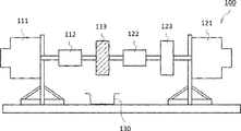
- FIG. 1 is a schematic cross-sectional view of the grease manufacturing apparatus of the above [1] that can be used in one embodiment of the present invention.
- the grease manufacturing apparatus 1 shown in FIG. 1 has a container body 2 for introducing a grease raw material inside and a rotating shaft 12 on the central axis of the inner circumference of the container body 2, and rotates around the rotating shaft 12 as the central axis. And a child 3.
- the rotor 3 rotates at a high speed about the rotating shaft 12 as a central axis, and gives a high shearing force to the grease raw material inside the container body 2. As a result, a grease containing a urea thickener is produced. As shown in FIG.
- the container body 2 may be partitioned into an introduction part 4, a retention part 5, a first inner peripheral surface 6, a second inner peripheral surface 7, and a discharge part 8 in order from the upstream side. preferable.
- the container body 2 preferably has a truncated cone-shaped inner peripheral surface whose inner diameter gradually increases from the introduction portion 4 to the discharge portion 8.
- the introduction portion 4 which is one end of the container main body 2 includes a plurality of solution introduction pipes 4A and 4B for introducing the grease raw material from the outside of the container main body 2.
- the retention section 5 is a space that is arranged downstream of the introduction section 4 and temporarily retains the grease raw material introduced from the introduction section 4. If the grease raw material stays in the retention portion 5 for a long time, the grease adhering to the inner peripheral surface of the retention portion 5 forms a large lump, so that the grease is conveyed to the first inner peripheral surface 6 on the downstream side in as short a time as possible. Preferably. More preferably, it is directly conveyed to the first inner peripheral surface 6 without passing through the retention portion 5.
- the first inner peripheral surface 6 is arranged in the downstream portion adjacent to the retention portion 5, and the second inner peripheral surface 7 is arranged in the downstream portion adjacent to the first inner peripheral surface 6.
- providing the first uneven portion 9 on the first inner peripheral surface 6 and providing the second uneven portion 10 on the second inner peripheral surface 7 mean that the first inner peripheral surface 6 and the second inner surface 6 It is preferable for the peripheral surface 7 to function as a high-shear portion that applies a high shear force to the grease raw material or the grease.
- the discharge part 8 which is the other end of the container body 2 is a part for discharging the grease agitated by the first inner peripheral surface 6 and the second inner peripheral surface 7, and has a discharge port 11 for discharging the grease.
- the discharge port 11 is formed in a direction orthogonal to or substantially orthogonal to the rotation axis 12.
- the discharge port 11 does not necessarily have to be orthogonal to the rotation shaft 12, and may be formed in a direction parallel to or substantially parallel to the rotation shaft 12.
- the rotor 3 is rotatably provided with the central axis of the truncated cone-shaped inner peripheral surface of the container body 2 as the rotation axis 12, and when the container body 2 is directed from the upstream portion to the downstream portion as shown in FIG. Then, rotate counterclockwise.
- the rotor 3 has an outer peripheral surface that expands as the inner diameter of the truncated cone of the container body 2 expands, and the outer peripheral surface of the rotor 3 and the inner peripheral surface of the truncated cone of the container body 2 are at regular intervals. Is maintained.
- the outer peripheral surface of the rotor 3 is provided with first uneven portions 13 of the rotor in which irregularities are alternately provided along the surface of the rotor 3.
- the first uneven portion 13 of the rotor is inclined from the introduction portion 4 in the discharge portion 8 direction with respect to the rotation shaft 12 of the rotor 3, and has a feeding ability from the introduction portion 4 to the discharge portion 8 direction. That is, the first uneven portion 13 of the rotor is inclined in the direction of pushing the solution downstream when the rotor 3 rotates in the direction shown in FIG.
- the step between the concave portion 13A and the convex portion 13B of the first uneven portion 13 of the rotor is preferably 0.3 to 30, more preferably 0.5, when the diameter of the concave portion 13A on the outer peripheral surface of the rotor 3 is 100. It is ⁇ 15, more preferably 2-7.
- the number of the convex portions 13B of the first concave-convex portion 13 of the rotor in the circumferential direction is preferably 2 to 1000, more preferably 6 to 500, and further preferably 12 to 200.
- the ratio of the width of the convex portion 13B of the first concave-convex portion 13 of the rotor to the width of the concave portion 13A in the cross section orthogonal to the rotation axis 12 of the rotor 3 [width of the convex portion / width of the concave portion] is preferably 0. It is 0.01 to 100, more preferably 0.1 to 10, and even more preferably 0.5 to 2.
- the inclination angle of the first concavo-convex portion 13 of the rotor with respect to the rotating shaft 12 is preferably 2 to 85 degrees, more preferably 3 to 45 degrees, and further preferably 5 to 20 degrees.
- the first inner peripheral surface 6 of the container body 2 is provided with the first uneven portion 9 in which a plurality of irregularities are formed along the inner peripheral surface. Further, it is preferable that the unevenness of the first uneven portion 9 on the container body 2 side is inclined in the direction opposite to that of the first uneven portion 13 of the rotor. That is, the plurality of irregularities of the first concave-convex portion 9 on the container body 2 side are inclined in the direction of pushing the solution downstream when the rotating shaft 12 of the rotor 3 rotates in the direction shown in FIG. Is preferred. The stirring capacity and the discharging capacity are further enhanced by the first uneven portion 9 having a plurality of irregularities provided on the first inner peripheral surface 6 of the container main body 2.
- the depth of the unevenness of the first uneven portion 9 on the container body 2 side is preferably 0.2 to 30, more preferably 0.5 to 15, and further preferably 1 to 1, when the container inner diameter (diameter) is 100. It is 5.
- the number of irregularities on the first concave-convex portion 9 on the container body 2 side is preferably 2 to 1000, more preferably 6 to 500, and even more preferably 12 to 200.
- the ratio of the width of the concave-convex concave portion of the first uneven portion 9 on the container body 2 side to the width of the convex portion between the grooves [width of the concave portion / width of the convex portion] is preferably 0.01 to 100, more preferably. Is 0.1 to 10, more preferably 0.5 to 2 or less.
- the inclination angle of the unevenness of the first uneven portion 9 on the container body 2 side with respect to the rotation axis 12 is preferably 2 to 85 degrees, more preferably 3 to 45 degrees, and further preferably 5 to 20 degrees.
- the first inner peripheral surface 6 of the container body 2 is provided with the first concave-convex portion 9, the first inner peripheral surface 6 can function as a shearing portion that applies a high shearing force to the grease raw material or the grease.
- the first uneven portion 9 does not necessarily have to be provided.
- the outer peripheral surface of the downstream portion of the first concavo-convex portion 13 of the rotor is provided with the second concavo-convex portion 14 of the rotor having the concavities and convexities alternately provided along the surface of the rotor 3.
- the second concavo-convex portion 14 of the rotor is inclined with respect to the rotation shaft 12 of the rotor 3 and has a feed suppressing ability that pushes the solution back to the upstream side from the introducing portion 4 toward the discharging portion 8.
- the step difference of the second concave-convex portion 14 of the rotor is preferably 0.3 to 30, more preferably 0.5 to 15, and further preferably 2 to 7 when the diameter of the concave portion of the outer peripheral surface of the rotor 3 is 100. Is.
- the number of protrusions of the second uneven portion 14 of the rotor in the circumferential direction is preferably 2 to 1000, more preferably 6 to 500, and further preferably 12 to 200.
- the ratio of the width of the convex portion of the second uneven portion 14 of the rotor to the width of the concave portion [width of the convex portion / width of the concave portion] in the cross section orthogonal to the rotation axis of the rotor 3 is preferably 0.01 to. 100, more preferably 0.1 to 10, and still more preferably 0.5 to 2.
- the inclination angle of the second concavo-convex portion 14 of the rotor with respect to the rotating shaft 12 is preferably 2 to 85 degrees, more preferably 3 to 45 degrees, and further preferably 5 to 20 degrees.
- the second inner peripheral surface 7 of the container body 2 is provided with a second concavo-convex portion 10 having a plurality of concavities and convexities adjacent to a downstream portion of the concavo-convex portion of the first concavo-convex portion 9 on the container body 2 side.
- a plurality of irregularities are formed on the inner peripheral surface of the container main body 2, and each unevenness is inclined in a direction opposite to the inclined direction of the second uneven portion 14 of the rotor.
- the plurality of concavities and convexities of the second concavo-convex portion 10 on the container body 2 side are inclined in a direction in which the solution is pushed back to the upstream side when the rotation shaft 12 of the rotor 3 rotates in the direction shown in FIG. Is preferable.
- the stirring capacity is further enhanced by the unevenness of the second uneven portion 10 provided on the second inner peripheral surface 7 of the container body 2.
- the second inner peripheral surface 7 of the container body can function as a grease raw material or a shearing portion that applies a high shearing force to the grease.
- the depth of the concave portion of the second uneven portion 10 on the container body 2 side is preferably 0.2 to 30, more preferably 0.5 to 15, and further preferably, when the inner diameter (diameter) of the container body 2 is 100. Is 1 to 5.
- the number of recesses of the second uneven portion 10 on the container body 2 side is preferably 2 to 1000, more preferably 6 to 500, and further preferably 12 to 200.
- the ratio of the width of the convex portion of the concave and convex of the second concave and convex portion 10 on the container body 2 side to the width of the concave portion in the cross section orthogonal to the rotation axis 12 of the rotor 3 [width of convex portion/width of concave portion] is preferably Is 0.01 to 100, more preferably 0.1 to 10, and even more preferably 0.5 to 2 or less.
- the inclination angle of the second uneven portion 10 on the container body 2 side with respect to the rotation axis 12 is preferably 2 to 85 degrees, more preferably 3 to 45 degrees, and further preferably 5 to 20 degrees.
- the ratio of the length of the first uneven portion 9 on the container body 2 side to the length of the second uneven portion 10 on the container body 2 side [length of the first uneven portion / length of the second uneven portion] is preferably It is 2/1 to 20/1.
- FIG. 2 is a cross-sectional view of the first uneven portion 9 on the container body 2 side of the grease manufacturing apparatus 1 in a direction orthogonal to the rotation axis 12.
- the first concavo-convex portion 13 of the rotor shown in FIG. 2 is provided with a plurality of scrapers 15 having a tip protruding toward the inner peripheral surface side of the container body 2 from the tip in the protruding direction of the convex portion 13B of the first concavo-convex portion 13.
- the second uneven portion 14 is also provided with a plurality of scrapers in which the tip of the convex portion projects toward the inner peripheral surface side of the container body 2, similarly to the first uneven portion 13.
- the scraper 15 scrapes off the grease attached to the inner peripheral surfaces of the first uneven portion 9 on the container body 2 side and the second uneven portion 10 on the container body 2 side.
- the amount of protrusion of the tip of the scraper 15 with respect to the amount of protrusion of the convex portion 13B of the first uneven portion 13 of the rotor is the ratio of the radius of the tip of the scraper 15 (R2) to the radius of the tip of the convex portion 13B (R1). It is preferable that [R2 / R1] exceeds 1.005 and is less than 2.0.
- the number of scrapers 15 is preferably 2 to 500, more preferably 2 to 50, and even more preferably 2 to 10. Although the scraper 15 is provided in the grease manufacturing apparatus 1 shown in FIG. 2, it may be provided without the scraper 15 or may be provided intermittently.
- the above-mentioned grease raw materials, solution ⁇ and solution ⁇ are mixed with the solution introduction pipe 4A of the introduction portion 4 of the container body 2. 4B, and the rotor 3 is rotated at a high speed to produce a grease base material containing the urea thickener (B). Then, even if the extreme pressure agent (C) and the other additive (D) are blended with the grease base material thus obtained, the above requirement (I) and further the above requirement (II) are satisfied.
- the urea-based thickener in the grease composition can be miniaturized.
- the shear rate applied to the grease raw material is preferably 10 2 s -1 or more, more preferably 10 3 s -1 or more, and further preferably 10 4 s -1 or more. , Usually 10 7 s -1 or less.
- the ratio (Max / Min) of the maximum shear rate (Max) to the minimum shear rate (Min) in shearing when the rotor 3 rotates at high speed is preferably 100 or less, more preferably 50 or less, still more preferably. It is 10 or less.
- the shear rate with respect to the mixed solution is as uniform as possible, the urea-based thickener and its precursor in the grease composition can be easily refined, resulting in a more uniform grease structure.
- the maximum shear rate (Max) is the maximum shear rate applied to the mixed solution
- the minimum shear rate (Min) is the minimum shear rate applied to the mixed solution. It is defined as follows.
- -Maximum shear rate (Max) (linear velocity of the tip of the convex portion 13B of the first concave-convex portion 13 of the rotor) / (tip of the convex portion 13B of the first concave-convex portion 13 of the rotor and the first inner circumference of the container body 2) Gap A1 of the convex portion of the first uneven portion 9 of the surface 6)
- -Minimum shear rate (Min) (Linear velocity of the concave portion 13A of the first concave-convex portion 13 of the rotor)/(Concave portion 13A of the first concave-convex portion 13 of the rotor and the first inner peripheral surface 6 of the container body 2) Gap A2 of the concave portion of one uneven portion 9)
- the grease manufacturing apparatus 1 includes the scraper 15, the grease attached to the inner peripheral surface of the container body 2 can be scraped off, so that it is possible to prevent lumps from being generated during kneading, and the urea-based It is possible to continuously manufacture a grease in which the thickener is finely divided, in a short time. Further, the scraper 15 scrapes off the adhered grease to prevent the retained grease from becoming a resistance to the rotation of the rotor 3, so that the rotational torque of the rotor 3 can be reduced, and the drive torque can be reduced. It is possible to reduce the power consumption of the source and efficiently perform continuous production of grease.
- a first uneven portion 13 of the rotor is provided on the outer peripheral surface of the rotor 3, and the first uneven portion 13 of the rotor is inclined with respect to the rotation axis 12 of the rotor 3, and from the introduction portion 4 to the discharge portion 8.
- the second uneven portion 14 of the rotor is inclined with respect to the rotation shaft 12 of the rotor 3, and has the ability to suppress the feed from the introduction portion 4 to the discharge portion 8.
- the urea-based thickener (B) in the grease composition is finely divided so as to be able to impart a high shearing force and to satisfy the above requirement (I) and further the above requirement (II) even after the additive is blended. Can be converted.
- the first uneven portion 9 is formed on the first inner peripheral surface 6 of the container body 2 and is inclined in the opposite direction to the first uneven portion 13 of the rotor, the effect of the first uneven portion 13 of the rotor is obtained.
- the urea-based thickener (B) in the grease composition can be miniaturized.
- the second uneven portion 10 is provided on the second inner peripheral surface 7 of the container body 2 and the second uneven portion 14 of the rotor is provided on the outer peripheral surface of the rotor 3, so that the grease raw material is unnecessary more than necessary.
- the urea-based thickener (B) can be miniaturized so as to satisfy the requirement (II).
- the grease composition of the present invention contains an extreme pressure agent (C) together with the components (A) and (B).
- an extreme pressure agent (C) Generally, in a grease composition containing a urea thickener (B), even if the extreme pressure agent (C) is added, the performance of the extreme pressure agent (C) is difficult to be exerted and It is difficult to impart wear resistance and load resistance to the grease composition.
- the performance of the extreme pressure agent (C) is extremely likely to be exhibited in the grease composition satisfying the above requirement (I) and further the above requirement (II). It was found that a grease composition having excellent wear resistance and load resistance is likely to be obtained.
- the extreme pressure agent (C) used in the grease composition of the present invention is one selected from organometallic extreme pressure agents, sulfur extreme pressure agents, phosphorus extreme pressure agents, and sulfur-phosphorus extreme pressure agents. That is all. Among these, one or more selected from organic metal-based extreme pressure agents, or sulfur-based extreme pressure agents, phosphorus-based extreme pressure agents, and sulfur-phosphorus-based agents from the viewpoint of further improving wear resistance and load resistance. A combination with an extreme pressure agent is preferable, and it is more preferable to use at least one selected from organometallic extreme pressure agents.
- the organometallic extreme pressure agent, the sulfur extreme pressure agent, the phosphorus extreme pressure agent, and the sulfur-phosphorus extreme pressure agent will be described.
- organic metal-based extreme pressure agent examples include organic molybdenum compounds such as molybdenum dialkyldithiocarbamate (MoDTC) and molybdenum dialkyldithiophosphate (MoDTP), zinc dialkyldithiophosphate (ZnDTC) and zinc dialkyldithiophosphate (ZnDTP), and the like. It is possible to use one or more selected from the organozinc compounds of.
- MoDTC molybdenum dialkyldithiocarbamate
- ZnDTP zinc dialkyldithiophosphate
- the content ratio of molybdenum dialkyldithiophosphate (MoDTC) to zinc dialkyldithiophosphate (ZnDTP) [(MoDTC) / (ZnDTP) )] is a mass ratio, preferably 1/10 to 10/1, more preferably 1/5 to 5/1, still more preferably 1/3 to 3/1.
- sulfur-based extreme pressure agent examples include sulfide fats and oils, sulfide fatty acids, sulfide esters, sulfide olefins, monosulfides, polysulfides, dihydrocarbyl polysulfides, thiadiazol compounds, alkylthiocarbamoyl compounds, thiocarbamate compounds, thioterpene compounds, and dialkylthiodipropio.
- One or more selected from nate compounds can be used. Among these, from the viewpoint of further improving wear resistance and load resistance, it is preferable to use either a sulfide oil or fat or a thiocarbamate compound, and it is more preferable to use these in combination.
- phosphorus-based extreme pressure agent examples include phosphate esters such as aryl phosphate, alkyl phosphate, alkenyl phosphate, and alkyl aryl phosphate; monoaryl acid phosphate, diallyl acid phosphate, monoalkyl acid phosphate, dialkyl acid phosphate, and monoalkenyl acid phosphate.
- Acidic phosphates such as dialkenyl acid phosphate; Hypophosphates such as arylhydrogen phosphite, alkylhydrogen phosphite, aryl phosphite, alkyl phosphite, alkenyl phosphite, arylalkyl phosphite; monoalkyl acid phosphite.
- Acid diphosphite such as dialkyl acid phosphite, monoalkenyl acid phosphite and dialkenyl acid phosphite; and one or more selected from these amine salts.
- sulfur-phosphorus extreme pressure agent for example, monoalkylthiophosphate, dialkyldithiophosphate, trialkyltrithiophosphate, and amine salts thereof, and one or more selected from zinc dialkyldithiophosphate (Zn-DTP) are used. be able to. Among these, it is preferable to use monoalkyl thiophosphate from the viewpoint of further improving wear resistance and load resistance.
- Examples of the combination of the sulfur-based extreme pressure agent, the phosphorus-based extreme pressure agent, and the sulfur-phosphorus-based extreme pressure agent include the combinations of the above-exemplified compounds, but from the viewpoint of further improving wear resistance and load resistance.
- a combination of a sulfurized fat and oil, a thiocarbamate compound, an amine salt of an acidic phosphoric acid ester, and a monoalkylthiophosphate is preferable.
- the sulfur-based extreme pressure agent, the phosphorus-based extreme pressure agent, and the sulfur-phosphorus-based extreme pressure agent are preferably metal-free compounds.
- the content of the extreme pressure agent (C) in the grease composition of one aspect of the present invention is preferably 0.1 to 10% by mass, more preferably 0, based on the total amount (100% by mass) of the grease composition. It is 5.5 to 8.0% by mass, more preferably 1.0 to 6.0% by mass.
- the grease composition of one aspect of the present invention contains an additive (D) other than the component (B) and the component (C), which is added to a general grease, within a range that does not impair the effects of the present invention. May be.
- the additive (D) include an antioxidant, a rust preventive, a dispersant, and a metal deactivator.
- the additive (D) one type may be used alone, or two or more types may be used in combination.
- antioxidants examples include amine antioxidants such as diphenylamine compounds and naphthylamine compounds, and phenolic antioxidants such as monocyclic phenol compounds and polycyclic phenol compounds.
- rust preventive examples include carboxylic acid-based rust preventives such as alkenyl succinic acid polyhydric alcohol ester, zinc stearate, thiadiazol and its derivatives, benzotriazole and its derivatives, and the like.
- the dispersant examples include ashless dispersants such as succinimide and boron-based succinimide.
- metal deactivator examples of the metal deactivator include benzotriazole compounds.
- the content of the additive (D) is usually 0.01 to 20% by mass, preferably 0.01 to 20% by mass, based on the total amount (100% by mass) of the grease composition.
- the amount is 0.01 to 15% by mass, more preferably 0.01 to 10% by mass, and further preferably 0.01 to 7% by mass.
- the grease composition of the present invention comprises a grease containing a base oil (A) and a urea-based thickener (B) synthesized by the above method, an extreme pressure agent (C), and an additive (D) if necessary. ) And can be manufactured.
- the extreme pressure agent (C) and optionally the additive (D) may be added to the grease and then stirred, or the extreme pressure agent (C) and, if necessary, the additive may be added while stirring the grease. It can be produced by blending (D) with the grease.
- the viscosity of the grease composition of one embodiment of the present invention at 25° C. is preferably 240 to 450, more preferably 260 to 450, further preferably 300 to 450, still more preferably 340 to 450, and still more preferably. Is 380 to 450.
- the grease composition of one aspect of the present invention has excellent leakage prevention performance, torque transmission efficiency and leakage prevention performance even when the mixing consistency at 25 ° C. is adjusted to the above range. It becomes a thing.
- the mixing consistency of the grease composition means a value measured at 25 ° C. in accordance with the ASTM D 217 method.
- the torque transmission efficiency measured and calculated by the method described in Examples described later is preferably 50% or more, more preferably 60% or more, still more preferably 70% or more, and more. It is more preferably 80% or more.
- the grease leakage rate measured and calculated by the method described in Examples described later is preferably less than 5.0%, more preferably 2.0% or less, still more preferably. It is 1.0% or less, more preferably 0.5% or less, still more preferably 0%.
- the wear resistance (fretting wear) measured by the method described in Examples described later in accordance with ASTM D 4170 is preferably 15 mg or less, more preferably 10 mg or less. It is even more preferably 8 mg or less, and even more preferably 7 mg or less.
- the load resistance (fusion load: WL) is preferably more than 1961 N, It is more preferably 2452N or more, still more preferably 3089N or more.
- the grease composition of the present invention is excellent in both torque transmission efficiency and leakage prevention performance, and is also excellent in abrasion resistance and load resistance. Therefore, the grease composition of one aspect of the present invention can be used as a lubricating part for a lubricating part such as a bearing part, a sliding part, a gear part, and a joint part of an apparatus for which such characteristics are required. Specifically, it can be used for hub units, electric power steering, electric motor flywheels for driving, ball joints, wheel bearings, spline parts, constant velocity joints, clutch boosters, servo motors, blade bearings or bearing parts of generators. Especially preferable.
- the fields of the apparatus in which the grease composition of the present invention can be preferably used also include the fields of automobiles, office equipment, machine tools, wind turbines, construction, agricultural machinery, industrial robots, and the like. ..
- Examples of the lubricated portion in the apparatus for automobiles, which can preferably use the grease composition of the present invention include a radiator fan motor, a fan coupling, an alternator, an idler pulley, a hub unit, a water pump, and a power window.
- Wiper electric power steering, electric motor flywheel for driving, ball joint, wheel bearing, spline part, constant velocity joint, etc. bearing part in the device; door lock, door hinge, clutch booster, etc. bearing part in the device, gear Part, sliding part; and the like.
- Examples of the lubricating portion in an apparatus in the field of office equipment to which the grease composition of the present invention can be preferably used include a fixing roll in an apparatus such as a printer, a bearing and a gear portion in an apparatus such as a polygon motor, and the like. Can be mentioned.
- Examples of the lubricating portion in the device in the machine tool field in which the grease composition of the present invention can be preferably used include a bearing portion in a speed reducer such as a spindle, a servomotor, and a machine tool robot.
- Examples of the lubricating portion in the apparatus in the wind turbine field in which the grease composition of the present invention can be preferably used include a blade bearing and a bearing portion such as a generator.
- the grease composition of the present invention can be preferably used, as a lubricating portion in a device for the field of construction or agricultural machinery, for example, a ball joint, a bearing portion such as a spline portion, a gear portion and a sliding portion. Can be mentioned. It can be suitably used for a speed reducer provided in an industrial robot or the like and a speed increaser provided in a wind power generation facility. Examples of the speed reducer and speed increaser include a speed reducer having a gear mechanism and a speed increaser having a gear mechanism.
- the application target of the grease composition of one aspect of the present invention is not limited to a speed reducer composed of a gear mechanism and a speed increaser composed of a gear mechanism, and can be applied to, for example, a traction drive.
- a device preferably a speed reducer or a speed increaser, is provided in which the grease composition of the present invention is provided at a lubrication portion such as a bearing portion, a sliding portion, a gear portion, or a joint portion.
- the grease composition of the present invention lubricates a lubricated portion (for example, a bearing portion, a sliding portion, a gear portion, a joint portion, etc.) of a device such as a speed reducer or a speed increaser.
- a lubrication method is provided.
- ⁇ Example 1> (1) Synthesis of urea grease (x-1) To 41.39 parts by mass of base oil (A1), 4.71 parts by mass of diphenylmethane-4,4′-diisocyanate (MDI) was added to prepare a solution ⁇ . In addition, solution ⁇ was prepared by adding 5.91 parts by mass of octadecylamine and 1.45 parts by mass of cyclohexylamine to 38.74 parts by mass of the base oil (A1) prepared separately. Then, using the grease manufacturing apparatus 1 shown in FIG. 1, the solution ⁇ heated to 70° C. is supplied from the solution introducing pipe 4A at a flow rate of 150 L/h, and the solution ⁇ heated to 70° C.
- MDI diphenylmethane-4,4′-diisocyanate
- the urea-based thickener contained in the urea grease (x-1) is a compound in which R 1 and R 2 in the general formula (b1) are selected from an octadecyl group and a cyclohexyl group, and R 3 is a diphenylmethylene group. Equivalent to. The molar ratio of octadecylamine and cyclohexylamine used as a raw material (octadecylamine/cyclohexylamine) is 60/40.
- urea grease (x-2) A solution ⁇ was prepared by adding 3.88 parts by mass of diphenylmethane-4,4′-diisocyanate (MDI) to 42.22 parts by mass of the base oil (A1). Further, a solution ⁇ was prepared by adding 8.10 parts by mass of octadecylamine to 38.00 parts by mass of the base oil (A1) prepared separately. Then, urea grease (x-2) was synthesized under the same conditions as (1) of Example 1 using the grease manufacturing apparatus 1 shown in FIG.
- MDI diphenylmethane-4,4′-diisocyanate
- the urea-based thickener contained in the urea grease (x-2) corresponds to a compound in which R 1 and R 2 in the general formula (b1) are octadecyl groups and R 3 is a diphenylmethylene group.
- the molar ratio of octadecylamine and cyclohexylamine used as a raw material (octadecylamine/cyclohexylamine) is 100/0.
- urea grease (x-3) 5.49 parts by mass of diphenylmethane-4,4′-diisocyanate (MDI) was added to 40.61 parts by mass of base oil (A1) to prepare a solution ⁇ . Further, 5.50 parts by mass of octylamine was added to 40.60 parts by mass of the base oil (A1) prepared separately to prepare a solution ⁇ . Then, urea grease (x-3) was synthesized under the same conditions as (1) of Example 1 using the grease manufacturing apparatus 1 shown in FIG.
- MDI diphenylmethane-4,4′-diisocyanate
- the urea-based thickener contained in the urea grease (x-3) corresponds to a compound in which R 1 and R 2 in the general formula (b1) are octyl groups and R 3 is a diphenylmethylene group.
- the molar ratio of octylamine to cyclohexylamine (octylamine / cyclohexylamine) used as a raw material is 100/0.
- (2) Preparation of grease composition (X3) In the above (1), the urea grease (x-3) discharged from the grease manufacturing apparatus 1 shown in FIG. 1 is stirred, and then naturally cooled to cool it to an extreme pressure.
- the agent (C5) and the extreme pressure agent (C6), as well as the additive (D1), the additive (D2), and the additive (D3) were added in the blending amounts shown in Table 1 to obtain a grease composition (X3).
- urea grease (x-4) A solution ⁇ was prepared by adding 1.95 parts by mass of diphenylmethane-4,4′-diisocyanate (MDI) to 44.25 parts by mass of base oil (A1). In addition, a solution ⁇ was prepared by adding 2.45 parts by mass of octadecylamine and 0.60 part by mass of cyclohexylamine to 43.15 parts by mass of the base oil (A1) prepared separately. Then, urea grease (x-4) was synthesized using the grease manufacturing apparatus 1 shown in FIG. 1 under the same conditions as (1) of Example 1.
- MDI diphenylmethane-4,4′-diisocyanate
- the urea-based thickener contained in the urea grease (x-4) is a compound in which R 1 and R 2 in the general formula (b1) are selected from an octadecyl group and a cyclohexyl group, and R 3 is a diphenylmethylene group. Equivalent to. The molar ratio of octadecylamine to cyclohexylamine (octadecylamine / cyclohexylamine) used as a raw material is 60/40.
- (2) Preparation of grease composition (X4) In the above (1), the urea grease (x-4) discharged from the grease manufacturing apparatus 1 shown in FIG. 1 was stirred and then cooled by natural cooling to extreme pressure.
- the table below shows the agents (C1), extreme pressure agents (C2), extreme pressure agents (C3), and extreme pressure agents (C4), as well as additives (D1), additives (D2), and additives (D3).
- the compounding amount shown in 1 was added to obtain a grease composition (X4).
- urea grease (x-5) A solution ⁇ was prepared by adding 1.76 parts by mass of diphenylmethane-4,4′-diisocyanate (MDI) to 44.34 parts by mass of base oil (A3). Further, to a separately prepared 43.36 parts by mass of base oil (A3), 2.20 parts by mass of octadecylamine and 0.54 parts by mass of cyclohexylamine were added to prepare a solution ⁇ . Then, urea grease (x-5) was synthesized using the grease manufacturing apparatus 1 shown in FIG. 1 under the same conditions as (1) of Example 1.
- MDI diphenylmethane-4,4′-diisocyanate
- the urea-based thickener contained in the urea grease (x-5) is a compound in which R 1 and R 2 in the general formula (b1) are selected from an octadecyl group and a cyclohexyl group, and R 3 is a diphenylmethylene group. Equivalent to. The molar ratio of octadecylamine and cyclohexylamine used as a raw material (octadecylamine/cyclohexylamine) is 60/40.
- (2) Preparation of Grease Composition (X5) In the above (1), the urea grease (x-5) discharged from the grease manufacturing apparatus 1 shown in FIG. 1 is stirred, cooled by natural cooling, and extreme pressure. Agent (C5) and extreme pressure agent (C6), as well as additive (D1), additive (D2), and additive (D3) in the compounding amounts shown in Table 1, grease composition (X5) Got
- urea grease (x-6) A solution ⁇ was prepared by adding 1.20 parts by mass of diphenylmethane-4,4′-diisocyanate (MDI) to 44.90 parts by mass of base oil (A2). In addition, a solution ⁇ was prepared by adding 1.51 parts by mass of octadecylamine and 0.37 parts by mass of cyclohexylamine to 44.22 parts by mass of the base oil (A2) prepared separately. Then, urea grease (x-6) was synthesized under the same conditions as (1) of Example 1 using the grease manufacturing apparatus 1 shown in FIG.
- MDI diphenylmethane-4,4′-diisocyanate
- the urea-based thickener contained in the urea grease (x-6) is a compound in which R 1 and R 2 in the general formula (b1) are selected from an octadecyl group and a cyclohexyl group, and R 3 is a diphenylmethylene group. Equivalent to. The molar ratio of octadecylamine and cyclohexylamine used as a raw material (octadecylamine/cyclohexylamine) is 60/40.
- (2) Preparation of Grease Composition (X6) In the above (1), the urea grease (x-6) discharged from the grease manufacturing apparatus 1 shown in FIG. 1 is stirred, cooled by natural cooling, and extreme pressure. The agent (C5) and the extreme pressure agent (C6), as well as the additive (D1), the additive (D2), and the additive (D3) were added in the blending amounts shown in Table 1 to obtain a grease composition (X6).
- urea grease (x-7) To 45.00 parts by mass of base oil (A2), 1.20 parts by mass of diphenylmethane-4,4'-diisocyanate (MDI) was added to prepare a solution ⁇ . Further, a solution ⁇ was prepared by adding 1.51 parts by mass of octadecylamine and 0.37 parts by mass of cyclohexylamine to 44.32 parts by mass of the base oil (A2) prepared separately. Then, urea grease (x-7) was synthesized under the same conditions as (1) of Example 1 using the grease manufacturing apparatus 1 shown in FIG.
- MDI diphenylmethane-4,4'-diisocyanate
- the urea-based thickener contained in the urea grease (x-7) is a compound in which R 1 and R 2 in the general formula (b1) are selected from an octadecyl group and a cyclohexyl group, and R 3 is a diphenylmethylene group. Equivalent to. The molar ratio of octadecylamine and cyclohexylamine used as a raw material (octadecylamine/cyclohexylamine) is 60/40.
- (2) Preparation of Grease Composition (X7) In the above (1), the urea grease (x-7) discharged from the grease manufacturing apparatus 1 shown in FIG. 1 is stirred, cooled by natural cooling, and extreme pressure.
- the table shows the agents (C1), extreme pressure agents (C2), extreme pressure agents (C3), and extreme pressure agents (C4), as well as additives (D1), additives (D2), and additives (D3).
- the grease composition (X7) was obtained by adding in the blending amount shown in 1.
- urea grease (x-8) A solution ⁇ was prepared by adding 1.95 parts by mass of diphenylmethane-4,4′-diisocyanate (MDI) to 44.15 parts by mass of base oil (A1). .. Further, separately prepared 43.05 parts by mass of the base oil (A1) was added with 2.45 parts by mass of octadecylamine and 0.60 parts by mass of cyclohexylamine to prepare a solution ⁇ . Then, using the grease manufacturing apparatus 1 shown in FIG. 1, urea grease (x-8) was synthesized under the same conditions as (1) of Example 1.
- MDI diphenylmethane-4,4′-diisocyanate
- the urea-based thickener contained in the urea grease (x-8) is a compound in which R 1 and R 2 in the general formula (b1) are selected from an octadecyl group and a cyclohexyl group, and R 3 is a diphenylmethylene group. Equivalent to. The molar ratio of octadecylamine to cyclohexylamine (octadecylamine / cyclohexylamine) used as a raw material is 60/40.
- (2) Preparation of Grease Composition (X8) In the above (1), the urea grease (x-8) discharged from the grease manufacturing apparatus 1 shown in FIG. 1 is stirred, cooled by natural cooling, and extreme pressure. The agent (C5) and the extreme pressure agent (C6), as well as the additive (D1), the additive (D2), and the additive (D3) were added in the blending amounts shown in Table 1, and the grease composition (X8) was added.
- ⁇ Comparative Example 1> (1) Synthesis of urea grease (y-1) A solution ⁇ was prepared by adding 5.85 parts by mass of diphenylmethane-4,4′-diisocyanate (MDI) to 40.25 parts by mass of the base oil (A1). A solution ⁇ was prepared by adding 7.34 parts by mass of octadecylamine and 1.80 parts by mass of cyclohexylamine to 36.96 parts by mass of the base oil (A1) prepared separately. Then, using the grease manufacturing apparatus shown in FIG. 3, the solution ⁇ heated to 70° C. was introduced into the container main body from the solution introducing pipe at a flow rate of 504 L/h. Then, the solution ⁇ heated to 70° C.
- MDI diphenylmethane-4,4′-diisocyanate
- the urea-based thickener contained in the urea grease (y-1) is a compound in which R 1 and R 2 in the general formula (b1) are selected from a cyclohexyl group and an octadecyl group, and R 3 is a diphenylmethylene group. Equivalent to. The molar ratio of octadecylamine to cyclohexylamine (octadecylamine / cyclohexylamine) used as a raw material is 60/40.
- (2) Preparation of Grease Composition (Y1) In the above (1), the urea grease (y-1) discharged from the grease manufacturing apparatus shown in FIG.
- urea grease (y-2) 1.04 parts by mass of diphenylmethane-4,4′-diisocyanate (MDI) was added to 45.09 parts by mass of base oil (A3) to prepare a solution ⁇ . .. Further, to a separately prepared 44.53 parts by mass of the base oil (A3), 1.26 parts by mass of octadecylamine and 0.31 part by mass of cyclohexylamine were added to prepare a solution ⁇ . Then, urea grease (y-2) was synthesized under the same conditions as (1) of Comparative Example 1 using the grease manufacturing apparatus shown in FIG.
- MDI diphenylmethane-4,4′-diisocyanate
- the urea-based thickener contained in the urea grease (y-2) is a compound in which R 1 and R 2 in the general formula (b1) are selected from cyclohexyl groups and octadecyl groups, and R 3 is a diphenylmethylene group. Equivalent to. The molar ratio of octadecylamine to cyclohexylamine (octadecylamine / cyclohexylamine) used as a raw material is 60/40.
- (2) Preparation of grease composition (Y2) In the above (1), the urea grease (y-2) discharged from the grease manufacturing apparatus shown in FIG. 3 is stirred and then naturally cooled to cool the extreme pressure agent. (C5) and the extreme pressure agent (C6) and the additive (D1), the additive (D2), and the additive (D3) were added in the compounding amounts shown in Table 2 to obtain a grease composition (Y2). ..
- urea grease (y-3) A solution ⁇ was prepared by adding 4.90 parts by mass of diphenylmethane-4,4′-diisocyanate (MDI) to 44.35 parts by mass of base oil (A4). .. Further, 4.89 parts by mass of octadecylamine and 1.20 parts by mass of cyclohexylamine were added to 42.16 parts by mass of the base oil (A4) prepared separately to prepare a solution ⁇ . Then, using the grease manufacturing apparatus shown in FIG. 3, urea grease (Y3) was synthesized under the same conditions as in (1) of Comparative Example 1.
- MDI diphenylmethane-4,4′-diisocyanate
- the urea-based thickener contained in the urea grease (y-3) is a compound in which R 1 and R 2 in the general formula (b1) are selected from cyclohexyl groups and octadecyl groups, and R 3 is a diphenylmethylene group. Equivalent to. The molar ratio of octadecylamine to cyclohexylamine (octadecylamine / cyclohexylamine) used as a raw material is 60/40.
- (2) Preparation of grease composition (Y3) In the above (1), urea grease (y-3) discharged from the grease production apparatus shown in FIG. 3 was stirred, and then naturally cooled to cool the additive ( D1), the additive (D2), and the additive (D3) were added in the blending amounts shown in Table 2 to obtain a grease composition (Y3).
- urea grease (y-4) To 44.15 parts by mass of base oil (A1), 1.95 parts by mass of diphenylmethane-4,4′-diisocyanate (MDI) was added to prepare a solution ⁇ . Further, separately prepared 43.05 parts by mass of the base oil (A1) was added with 2.45 parts by mass of octadecylamine and 0.60 parts by mass of cyclohexylamine to prepare a solution ⁇ . Then, urea grease (y-4) was synthesized under the same conditions as (1) of Comparative Example 1 using the grease manufacturing apparatus shown in FIG.
- MDI diphenylmethane-4,4′-diisocyanate
- the urea-based thickener contained in the urea grease (y-4) is a compound in which R 1 and R 2 in the general formula (b1) are selected from cyclohexyl groups and octadecyl groups, and R 3 is a diphenylmethylene group. Equivalent to. The molar ratio of octadecylamine to cyclohexylamine (octadecylamine / cyclohexylamine) used as a raw material is 60/40.
- (2) Preparation of Grease Composition (Y4) In the above (1), the urea grease (y-4) discharged from the grease manufacturing apparatus shown in FIG. 3 is stirred and then naturally cooled to cool the extreme pressure agent. (C5) and the extreme pressure agent (C6) and the additive (D1), the additive (D2), and the additive (D3) were added in the compounding amounts shown in Table 2 to obtain a grease composition (Y4). ..
- urea grease (y-5) To 46.40 parts by mass of base oil (A1), 1.95 parts by mass of diphenylmethane-4,4'-diisocyanate (MDI) was added to prepare a solution ⁇ . In addition, a solution ⁇ was prepared by adding 2.45 parts by mass of octadecylamine and 0.60 parts by mass of cyclohexylamine to 45.30 parts by mass of the base oil (A1) prepared separately. Then, urea grease (y-5) was synthesized under the same conditions as (1) of Comparative Example 1 using the grease manufacturing apparatus shown in FIG.
- MDI diphenylmethane-4,4'-diisocyanate
- the urea-based thickener contained in the urea grease (y-5) is a compound in which R 1 and R 2 in the general formula (b1) are selected from cyclohexyl groups and octadecyl groups, and R 3 is a diphenylmethylene group. Equivalent to. The molar ratio of octadecylamine to cyclohexylamine (octadecylamine / cyclohexylamine) used as a raw material is 60/40.
- (2) Preparation of Grease Composition (Y5) In the above (1), the urea grease (y-5) discharged from the grease manufacturing apparatus shown in FIG. 3 is stirred and then cooled by natural cooling to add an additive (Y-5). D1), the additive (D2), and the additive (D3) were added in the compounding amounts shown in Table 2 to obtain a grease composition (Y5).
- urea grease (y-6) To 44.25 parts by mass of base oil (A1), 1.95 parts by mass of diphenylmethane-4,4'-diisocyanate (MDI) was added to prepare a solution ⁇ . In addition, a solution ⁇ was prepared by adding 2.45 parts by mass of octadecylamine and 0.60 part by mass of cyclohexylamine to 43.15 parts by mass of the base oil (A1) prepared separately. Then, urea grease (y-6) was synthesized under the same conditions as in Synthesis Example Y1 using the grease manufacturing apparatus shown in FIG.
- MDI diphenylmethane-4,4'-diisocyanate
- the urea-based thickener contained in the urea grease (y-6) is a compound in which R 1 and R 2 in the general formula (b1) are selected from cyclohexyl groups and octadecyl groups, and R 3 is a diphenylmethylene group. Equivalent to. The molar ratio of octadecylamine to cyclohexylamine (octadecylamine / cyclohexylamine) used as a raw material is 60/40.
- (2) Preparation of Grease Composition (Y6) In the above (1), the urea grease (y-6) discharged from the grease manufacturing apparatus shown in FIG. 3 is stirred, cooled by natural cooling, and an extreme pressure agent. (C1), extreme pressure agent (C2), extreme pressure agent (C3), and extreme pressure agent (C4) and additive (D1), additive (D2), and additive (D3) are shown in Table 2. The grease composition (Y6) was obtained by adding in a blending amount
- urea grease (y-7) A solution ⁇ was prepared by adding 1.95 parts by mass of diphenylmethane-4,4′-diisocyanate (MDI) to 46.40 parts by mass of the base oil (A1). In addition, a solution ⁇ was prepared by adding 2.45 parts by mass of octadecylamine and 0.60 parts by mass of cyclohexylamine to 45.30 parts by mass of the base oil (A1) prepared separately. Then, using the grease producing apparatus 1 shown in FIG. 1, urea grease (y-7) was synthesized under the same conditions as (1) of Example 1.
- MDI diphenylmethane-4,4′-diisocyanate
- the urea-based thickener contained in the urea grease (y-7) is a compound in which R 1 and R 2 in the general formula (b1) are selected from an octadecyl group and a cyclohexyl group, and R 3 is a diphenylmethylene group. Equivalent to. The molar ratio of octadecylamine to cyclohexylamine (octadecylamine / cyclohexylamine) used as a raw material is 60/40.
- (2) Preparation of Grease Composition (Y7) In the above (1), the urea grease (y-7) discharged from the grease manufacturing apparatus 1 shown in FIG. 1 is stirred, cooled by natural cooling, and added. (D1), additive (D2), and additive (D3) were added in the compounding amounts shown in Table 2 to obtain a grease composition (Y7).
- the measurement sample was degassed in vacuum and filled in a 1 mL syringe, and 0.10 to 0.15 mL of the sample was extruded from the syringe, and the extruded sample was placed on the surface of the plate cell of the paste cell fixing jig. .. Then, another plate-shaped cell was superposed on the sample to obtain a measurement cell in which the sample was sandwiched between the two cells.
- Area standard of particles particles containing urea-based thickener (B)
- LA-920 laser diffraction particle size analyzer
- the "arithmetic mean particle size on an area basis” means a value obtained by arithmetically averaging the particle size distribution on an area basis.
- the particle size distribution on an area basis indicates a frequency distribution of particle sizes in the whole particles to be measured, based on an area calculated from the particle size (specifically, a cross-sectional area of particles having the particle size). It is a thing.
- the value obtained by arithmetically averaging the particle size distribution on the basis of area can be calculated by the following formula (1).
- J means the division number of the particle size.
- q(J) means a frequency distribution value (unit: %).
- X (J) is a representative diameter (unit: ⁇ m) of the J-th particle diameter range.
- FIG. 4 is a schematic diagram of an apparatus used when measuring the torque transmission efficiency in the present embodiment.
- the measuring device 100 shown in FIG. 4 includes an input side motor unit 111, an input side torque measuring device 112, an input side reduction gear 113 (manufactured by Nabtesco Corporation, product name “RV-42N”), an output side torque measuring device 122, and an output.
- the side reducer 123 (manufactured by Nabtesco Corporation, product name “RV-125V”) and the output side motor unit 121 are connected in this order.
- the torque transmission efficiency is an index indicating the amount of power loss before the input power is output. The lower the torque transmission efficiency, the larger the power loss, and conversely, the higher the torque transmission efficiency, the smaller the power loss. ..
Landscapes
- Chemical & Material Sciences (AREA)
- Oil, Petroleum & Natural Gas (AREA)
- Chemical Kinetics & Catalysis (AREA)
- General Chemical & Material Sciences (AREA)
- Organic Chemistry (AREA)
- Engineering & Computer Science (AREA)
- General Engineering & Computer Science (AREA)
- Mechanical Engineering (AREA)
- Lubricants (AREA)
Abstract
La présente invention aborde le problème de la fourniture d'une composition de graisse qui contient un agent extrême pression et utilise un épaississant à base d'urée en tant qu'épaississant, et qui présente à la fois une excellente efficacité de transmission de couple et une excellente performance de prévention de fuite, et qui présente une excellente résistance à l'usure et une excellente résistance à la charge. Cette composition de graisse contient une huile de base (A), un épaississant à base d'urée (B) et un agent extrême pression (C). Les particules contenant l'épaississant à base d'urée (B) dans la composition de graisse satisfont à la condition (I) suivante: le diamètre de particule moyen arithmétique basé sur la surface des particules est d'au plus 2,0 µm tel que mesuré par un procédé de diffraction/diffusion laser. L'agent extrême pression (C) est au moins un élément choisi parmi un agent extrême pression organométallique, un agent extrême pression soufré, un agent extrême pression phosphoré et un agent extrême pression phosphosoufré.
Priority Applications (4)
| Application Number | Priority Date | Filing Date | Title |
|---|---|---|---|
| EP20765715.6A EP3936591B1 (fr) | 2019-03-06 | 2020-02-27 | Composition de graisse |
| CN202080018720.4A CN113508171B (zh) | 2019-03-06 | 2020-02-27 | 润滑脂组合物 |
| US17/435,733 US11555160B2 (en) | 2019-03-06 | 2020-02-27 | Grease composition |
| JP2021504010A JP7467410B2 (ja) | 2019-03-06 | 2020-02-27 | グリース組成物 |
Applications Claiming Priority (2)
| Application Number | Priority Date | Filing Date | Title |
|---|---|---|---|
| JP2019040945 | 2019-03-06 | ||
| JP2019-040945 | 2019-03-06 |
Publications (1)
| Publication Number | Publication Date |
|---|---|
| WO2020179595A1 true WO2020179595A1 (fr) | 2020-09-10 |
Family
ID=72337742
Family Applications (1)
| Application Number | Title | Priority Date | Filing Date |
|---|---|---|---|
| PCT/JP2020/007937 Ceased WO2020179595A1 (fr) | 2019-03-06 | 2020-02-27 | Composition de graisse |
Country Status (5)
| Country | Link |
|---|---|
| US (1) | US11555160B2 (fr) |
| EP (1) | EP3936591B1 (fr) |
| JP (1) | JP7467410B2 (fr) |
| CN (1) | CN113508171B (fr) |
| WO (1) | WO2020179595A1 (fr) |
Cited By (6)
| Publication number | Priority date | Publication date | Assignee | Title |
|---|---|---|---|---|
| JPWO2022211117A1 (fr) * | 2021-03-31 | 2022-10-06 | ||
| WO2022211119A1 (fr) * | 2021-03-31 | 2022-10-06 | 出光興産株式会社 | Composition de graisse |
| JP2023146942A (ja) * | 2022-03-29 | 2023-10-12 | コスモ石油ルブリカンツ株式会社 | グリース組成物 |
| JP2023151693A (ja) * | 2022-03-31 | 2023-10-16 | 出光興産株式会社 | グリース組成物 |
| WO2024150774A1 (fr) * | 2023-01-12 | 2024-07-18 | 出光興産株式会社 | Composition de graisse |
| JP7853956B2 (ja) | 2021-03-31 | 2026-04-30 | 出光興産株式会社 | グリース組成物 |
Families Citing this family (6)
| Publication number | Priority date | Publication date | Assignee | Title |
|---|---|---|---|---|
| US12153938B2 (en) * | 2020-11-03 | 2024-11-26 | Kpn Innovations, Llc. | Systems and methods for a configurable device environment |
| US11599614B2 (en) * | 2020-11-03 | 2023-03-07 | Kpn Innovations, Llc. | Systems and methods for a configurable device environment |
| KR20250055507A (ko) * | 2022-08-31 | 2025-04-24 | 교도유시 가부시끼가이샤 | 그리스 조성물 및 상기 그리스 조성물을 충전한 랙 앤 피니언식 스티어링 장치 |
| CN118834714B (zh) * | 2023-04-25 | 2026-03-06 | 中国石油化工股份有限公司 | 太阳能跟踪器回转支承用润滑脂及其原料组合物和制备方法 |
| CN117264683A (zh) * | 2023-11-22 | 2023-12-22 | 新乡市恒星科技有限责任公司 | 一种耐高温低噪音聚脲基工业机器人用润滑脂 |
| CN118294051B (zh) * | 2024-04-08 | 2025-03-28 | 恒丰泰精密机械股份有限公司 | 一种支撑稳定的浓密机检测结构 |
Citations (9)
| Publication number | Priority date | Publication date | Assignee | Title |
|---|---|---|---|---|
| JPH1121580A (ja) * | 1997-07-02 | 1999-01-26 | Nippon Sekiyu Kako Kk | ウレア系グリースの製造方法 |
| JP2004075041A (ja) * | 2003-05-06 | 2004-03-11 | Nsk Ltd | 電動パワーステアリング装置 |
| JP2004231714A (ja) * | 2003-01-29 | 2004-08-19 | Nsk Ltd | グリース組成物及び転動装置 |
| JP2005047938A (ja) * | 2003-06-02 | 2005-02-24 | Koyo Seiko Co Ltd | 潤滑剤組成物とそれを用いた減速機ならびにそれを用いた電動パワーステアリング装置 |
| JP2005247971A (ja) * | 2004-03-03 | 2005-09-15 | Nsk Ltd | 樹脂潤滑用グリース組成物、ギア装置及び電動パワーステアリング装置 |
| JP2008309336A (ja) * | 2008-07-29 | 2008-12-25 | Sumitomo Heavy Ind Ltd | 食品工場用の変速機 |
| WO2016125859A1 (fr) * | 2015-02-05 | 2016-08-11 | 出光興産株式会社 | Graisse et procédé de fabrication de graisse |
| JP2017115109A (ja) * | 2015-12-25 | 2017-06-29 | 出光興産株式会社 | グリース製造装置、及びグリースの製造方法 |
| JP2018115235A (ja) * | 2017-01-16 | 2018-07-26 | コスモ石油ルブリカンツ株式会社 | ウレア系グリース組成物 |
Family Cites Families (13)
| Publication number | Priority date | Publication date | Assignee | Title |
|---|---|---|---|---|
| US7135441B2 (en) * | 2000-11-06 | 2006-11-14 | Nsk Ltd. | Lubricating grease composition and rolling apparatus |
| JP4167878B2 (ja) | 2002-10-10 | 2008-10-22 | 住友重機械工業株式会社 | 食品工場用の変速機 |
| US7652088B2 (en) | 2003-06-25 | 2010-01-26 | Dic Corporation | Organic-inorganic composite material and method for producing the same |
| JP2011042747A (ja) | 2009-08-21 | 2011-03-03 | Kyodo Yushi Co Ltd | 減速機用グリース組成物及び減速機 |
| JP6618017B2 (ja) * | 2014-05-27 | 2019-12-11 | 出光興産株式会社 | ウレアグリース |
| JP6546727B2 (ja) * | 2014-08-29 | 2019-07-17 | 協同油脂株式会社 | グリース組成物 |
| JP6499022B2 (ja) | 2015-06-11 | 2019-04-10 | 本田技研工業株式会社 | 輸送機器部材用ポリウレア架橋粒子及び摺動部材 |
| JP6777285B2 (ja) * | 2016-11-30 | 2020-10-28 | 出光興産株式会社 | 混合グリース |
| JP6985032B2 (ja) * | 2017-05-22 | 2021-12-22 | 出光興産株式会社 | グリース組成物、及び精密減速機 |
| CN108715769A (zh) | 2018-06-29 | 2018-10-30 | 中国石油化工股份有限公司 | 一种高温半氟素润滑脂组合物及其制备方法和应用 |
| CN112639060B (zh) * | 2018-09-14 | 2022-12-09 | 出光兴产株式会社 | 等速万向节用润滑脂组合物 |
| US11746303B2 (en) * | 2019-01-31 | 2023-09-05 | Idemitsu Kosan Co., Ltd. | Grease composition |
| WO2020179603A1 (fr) * | 2019-03-06 | 2020-09-10 | 出光興産株式会社 | Composition de graisse |
-
2020
- 2020-02-27 EP EP20765715.6A patent/EP3936591B1/fr active Active
- 2020-02-27 JP JP2021504010A patent/JP7467410B2/ja active Active
- 2020-02-27 US US17/435,733 patent/US11555160B2/en active Active
- 2020-02-27 WO PCT/JP2020/007937 patent/WO2020179595A1/fr not_active Ceased
- 2020-02-27 CN CN202080018720.4A patent/CN113508171B/zh active Active
Patent Citations (9)
| Publication number | Priority date | Publication date | Assignee | Title |
|---|---|---|---|---|
| JPH1121580A (ja) * | 1997-07-02 | 1999-01-26 | Nippon Sekiyu Kako Kk | ウレア系グリースの製造方法 |
| JP2004231714A (ja) * | 2003-01-29 | 2004-08-19 | Nsk Ltd | グリース組成物及び転動装置 |
| JP2004075041A (ja) * | 2003-05-06 | 2004-03-11 | Nsk Ltd | 電動パワーステアリング装置 |
| JP2005047938A (ja) * | 2003-06-02 | 2005-02-24 | Koyo Seiko Co Ltd | 潤滑剤組成物とそれを用いた減速機ならびにそれを用いた電動パワーステアリング装置 |
| JP2005247971A (ja) * | 2004-03-03 | 2005-09-15 | Nsk Ltd | 樹脂潤滑用グリース組成物、ギア装置及び電動パワーステアリング装置 |
| JP2008309336A (ja) * | 2008-07-29 | 2008-12-25 | Sumitomo Heavy Ind Ltd | 食品工場用の変速機 |
| WO2016125859A1 (fr) * | 2015-02-05 | 2016-08-11 | 出光興産株式会社 | Graisse et procédé de fabrication de graisse |
| JP2017115109A (ja) * | 2015-12-25 | 2017-06-29 | 出光興産株式会社 | グリース製造装置、及びグリースの製造方法 |
| JP2018115235A (ja) * | 2017-01-16 | 2018-07-26 | コスモ石油ルブリカンツ株式会社 | ウレア系グリース組成物 |
Non-Patent Citations (1)
| Title |
|---|
| See also references of EP3936591A4 * |
Cited By (12)
| Publication number | Priority date | Publication date | Assignee | Title |
|---|---|---|---|---|
| JPWO2022211117A1 (fr) * | 2021-03-31 | 2022-10-06 | ||
| WO2022211117A1 (fr) * | 2021-03-31 | 2022-10-06 | 出光興産株式会社 | Composition de graisse |
| WO2022211119A1 (fr) * | 2021-03-31 | 2022-10-06 | 出光興産株式会社 | Composition de graisse |
| JPWO2022211119A1 (fr) * | 2021-03-31 | 2022-10-06 | ||
| CN117295807A (zh) * | 2021-03-31 | 2023-12-26 | 出光兴产株式会社 | 润滑脂组合物 |
| US12264293B2 (en) | 2021-03-31 | 2025-04-01 | Idemitsu Kosan Co., Ltd. | Grease composition |
| US12378498B2 (en) | 2021-03-31 | 2025-08-05 | Idemitsu Kosan Co., Ltd. | Grease composition |
| JP7821781B2 (ja) | 2021-03-31 | 2026-02-27 | 出光興産株式会社 | グリース組成物 |
| JP7853956B2 (ja) | 2021-03-31 | 2026-04-30 | 出光興産株式会社 | グリース組成物 |
| JP2023146942A (ja) * | 2022-03-29 | 2023-10-12 | コスモ石油ルブリカンツ株式会社 | グリース組成物 |
| JP2023151693A (ja) * | 2022-03-31 | 2023-10-16 | 出光興産株式会社 | グリース組成物 |
| WO2024150774A1 (fr) * | 2023-01-12 | 2024-07-18 | 出光興産株式会社 | Composition de graisse |
Also Published As
| Publication number | Publication date |
|---|---|
| US20220135897A1 (en) | 2022-05-05 |
| JP7467410B2 (ja) | 2024-04-15 |
| EP3936591A1 (fr) | 2022-01-12 |
| EP3936591B1 (fr) | 2024-11-13 |
| US11555160B2 (en) | 2023-01-17 |
| CN113508171A (zh) | 2021-10-15 |
| CN113508171B (zh) | 2023-06-06 |
| EP3936591A4 (fr) | 2022-11-23 |
| JPWO2020179595A1 (fr) | 2020-09-10 |
Similar Documents
| Publication | Publication Date | Title |
|---|---|---|
| JP7467410B2 (ja) | グリース組成物 | |
| JP7518813B2 (ja) | グリース組成物 | |
| CN115279875B (zh) | 润滑脂组合物 | |
| JP7442453B2 (ja) | 等速ジョイント用グリース組成物 | |
| US11746303B2 (en) | Grease composition | |
| WO2019044624A1 (fr) | Composition de graisse | |
| US12565624B2 (en) | Grease composition | |
| WO2024150774A1 (fr) | Composition de graisse | |
| JP2025123101A (ja) | グリース組成物、グリース組成物の製造方法、及び車軸の潤滑方法 |
Legal Events
| Date | Code | Title | Description |
|---|---|---|---|
| 121 | Ep: the epo has been informed by wipo that ep was designated in this application |
Ref document number: 20765715 Country of ref document: EP Kind code of ref document: A1 |
|
| ENP | Entry into the national phase |
Ref document number: 2021504010 Country of ref document: JP Kind code of ref document: A |
|
| NENP | Non-entry into the national phase |
Ref country code: DE |
|
| ENP | Entry into the national phase |
Ref document number: 2020765715 Country of ref document: EP Effective date: 20211006 |