WO2020183214A1 - Dispositif d'échange de chaleur pour véhicules - Google Patents
Dispositif d'échange de chaleur pour véhicules Download PDFInfo
- Publication number
- WO2020183214A1 WO2020183214A1 PCT/IB2019/000303 IB2019000303W WO2020183214A1 WO 2020183214 A1 WO2020183214 A1 WO 2020183214A1 IB 2019000303 W IB2019000303 W IB 2019000303W WO 2020183214 A1 WO2020183214 A1 WO 2020183214A1
- Authority
- WO
- WIPO (PCT)
- Prior art keywords
- radiator
- cooling water
- intercooler
- vehicle
- heat exchange
- Prior art date
- Legal status (The legal status is an assumption and is not a legal conclusion. Google has not performed a legal analysis and makes no representation as to the accuracy of the status listed.)
- Ceased
Links
Images



Classifications
-
- B—PERFORMING OPERATIONS; TRANSPORTING
- B60—VEHICLES IN GENERAL
- B60H—ARRANGEMENTS OF HEATING, COOLING, VENTILATING OR OTHER AIR-TREATING DEVICES SPECIALLY ADAPTED FOR PASSENGER OR GOODS SPACES OF VEHICLES
- B60H1/00—Heating, cooling or ventilating devices
- B60H1/32—Cooling devices
-
- B—PERFORMING OPERATIONS; TRANSPORTING
- B60—VEHICLES IN GENERAL
- B60K—ARRANGEMENT OR MOUNTING OF PROPULSION UNITS OR OF TRANSMISSIONS IN VEHICLES; ARRANGEMENT OR MOUNTING OF PLURAL DIVERSE PRIME-MOVERS IN VEHICLES; AUXILIARY DRIVES FOR VEHICLES; INSTRUMENTATION OR DASHBOARDS FOR VEHICLES; ARRANGEMENTS IN CONNECTION WITH COOLING, AIR INTAKE, GAS EXHAUST OR FUEL SUPPLY OF PROPULSION UNITS IN VEHICLES
- B60K11/00—Arrangement in connection with cooling of propulsion units
- B60K11/02—Arrangement in connection with cooling of propulsion units with liquid cooling
- B60K11/04—Arrangement or mounting of radiators, radiator shutters, or radiator blinds
-
- F—MECHANICAL ENGINEERING; LIGHTING; HEATING; WEAPONS; BLASTING
- F01—MACHINES OR ENGINES IN GENERAL; ENGINE PLANTS IN GENERAL; STEAM ENGINES
- F01P—COOLING OF MACHINES OR ENGINES IN GENERAL; COOLING OF INTERNAL-COMBUSTION ENGINES
- F01P7/00—Controlling of coolant flow
- F01P7/14—Controlling of coolant flow the coolant being liquid
- F01P7/16—Controlling of coolant flow the coolant being liquid by thermostatic control
-
- F—MECHANICAL ENGINEERING; LIGHTING; HEATING; WEAPONS; BLASTING
- F02—COMBUSTION ENGINES; HOT-GAS OR COMBUSTION-PRODUCT ENGINE PLANTS
- F02B—INTERNAL-COMBUSTION PISTON ENGINES; COMBUSTION ENGINES IN GENERAL
- F02B29/00—Engines characterised by provision for charging or scavenging not provided for in groups F02B25/00, F02B27/00 or F02B33/00 - F02B39/00; Details thereof
- F02B29/04—Cooling of air intake supply
-
- F—MECHANICAL ENGINEERING; LIGHTING; HEATING; WEAPONS; BLASTING
- F02—COMBUSTION ENGINES; HOT-GAS OR COMBUSTION-PRODUCT ENGINE PLANTS
- F02B—INTERNAL-COMBUSTION PISTON ENGINES; COMBUSTION ENGINES IN GENERAL
- F02B37/00—Engines characterised by provision of pumps driven at least for part of the time by exhaust
-
- Y—GENERAL TAGGING OF NEW TECHNOLOGICAL DEVELOPMENTS; GENERAL TAGGING OF CROSS-SECTIONAL TECHNOLOGIES SPANNING OVER SEVERAL SECTIONS OF THE IPC; TECHNICAL SUBJECTS COVERED BY FORMER USPC CROSS-REFERENCE ART COLLECTIONS [XRACs] AND DIGESTS
- Y02—TECHNOLOGIES OR APPLICATIONS FOR MITIGATION OR ADAPTATION AGAINST CLIMATE CHANGE
- Y02T—CLIMATE CHANGE MITIGATION TECHNOLOGIES RELATED TO TRANSPORTATION
- Y02T10/00—Road transport of goods or passengers
- Y02T10/10—Internal combustion engine [ICE] based vehicles
- Y02T10/12—Improving ICE efficiencies
Definitions
- the present invention relates to a vehicle heat exchanger including a radiator for an engine, a condenser for an air conditioner, and a radiator for a water-cooled intercooler.
- An engine equipped with a supercharger may be equipped with an intercooler that cools the intake air that has become hot due to supercharging before introducing it into the combustion chamber.
- This intercooler includes an air-cooled intercooler that exchanges heat between the high-temperature supercharged intake air and the outside air, and a water-cooled intercooler that exchanges heat between the high-temperature supercharged intake air and the cooling water.
- a radiator that cools the cooling water, which is the cooling medium, with the outside air is required.
- Patent Document 1 discloses a configuration in which a radiator for a water-cooled intercooler is arranged in front of a radiator for an engine, and a condenser for an air conditioner is arranged in front of the radiator. That is, three heat exchangers that exchange heat with the outside air are arranged in three stages in the front-rear direction, and a fan is arranged behind these heat exchangers.
- Patent Document 2 discloses a configuration in which a condenser for an air conditioner and an air-cooled intercooler are arranged side by side in the vehicle width direction in front of a radiator for an engine.
- a condenser for an air conditioner and an air-cooled intercooler are arranged side by side in the vehicle width direction in front of a radiator for an engine.
- the intercooler since it is an air-cooled intercooler, The handling of the intake system between the engine and the supercharger becomes complicated, and the increase in intake pressure loss and the increase in intake passage volume due to the lengthening of the intake passage become problems.
- the intercooler since the intercooler is small because it is arranged side by side with the condenser, the amount of heat exchange is limited. Since the size of the radiator required when the intercooler is a water-cooled intercooler is generally larger than that of the air-cooled intercooler, it is difficult to apply the layout of Patent Document 2 to the water-cooled intercooler. is there.
- the vehicle heat exchange device is A water-cooled engine cooled by the first cooling water, An intercooler that cools the supercharged intake air supplied to the engine, the first core portion on the upstream side of the intake air that is cooled by the first cooling water and the second core portion on the downstream side of the intake air that is cooled by the second cooling water.
- a two-stage water-cooled intercooler that includes two core parts, The first radiator, which is arranged at a position where the vehicle running wind is given and cools the first cooling water by exchanging heat with air, An air conditioner condenser arranged in front of the first radiator so as to overlap a part of the first radiator.
- a second radiator which is arranged in front of the first radiator so as to overlap a part of the first radiator and cools the second cooling water by heat exchange with air, and a second radiator.
- the first cooling water passes through the water-cooled engine to cool the engine, and at the same time, passes through the first core portion of the water-cooled intercooler to cool the supercharged intake air.
- the heat of the first cooling water that has become hot is dissipated by the first radiator.
- the second cooling water passes through the second core portion of the water-cooled intercooler to cool the supercharged intake air.
- the heat of this second cooling water is dissipated by the second radiator.
- the high-temperature supercharged intake air is first cooled by the first cooling water in the first core portion, and then further cooled by the second cooling water in the second core portion.
- the second cooling water can be kept cooler than the first cooling water, so that the supercharged intake air is efficiently cooled to a lower temperature.
- the second radiator for cooling the second cooling water can be configured to be relatively small. Therefore, the second radiator and the air conditioner capacitor can be arranged side by side in the vehicle vertical direction or the vehicle width direction, and three heat exchangers including the first radiator are arranged in two stages in the vehicle front-rear direction. Is placed in. As a result, the dimensions in the front-rear direction of the vehicle can be shortened, and the ventilation resistance against the vehicle running wind and the cooling air by the fan is reduced.
- the schematic which shows the overall structure of the heat exchange apparatus of the vehicle which concerns on this invention.
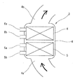
- the schematic diagram which shows the structure of the two-stage type water-cooled intercooler.
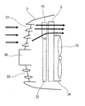
- the schematic view from the side of the vehicle which shows the heat exchanger part of FIG. Schematic view of the heat exchanger part and the shroud from the rear side.
- FIG. 1 is a schematic view showing the overall configuration of the vehicle heat exchange device according to the present invention, and schematically shows the configuration when the front part of the automobile is viewed from the side.
- This automobile includes, for example, an engine (internal combustion engine) 1 mounted horizontally on a vehicle body 2.
- the engine 1 may be a spark-ignition engine or a diesel engine using gasoline as fuel, and is a water-cooled engine having a water jacket inside.
- the engine 1 is equipped with a supercharger (not shown) such as a turbocharger or a mechanical supercharger, and further, a water-cooled intercooler 3 that cools the supercharged intake air that has become high temperature and high pressure by this supercharger. It has.
- the water-cooled intercooler 3 has a housing 4 in which supercharging intake air flows from the inlet 4a to the outlet 4b, and a cooling water inlet 5a and a cooling water outlet 5b located on the inlet 4a side. It includes a first core 5 having a first core 5 and a second core 6 located on the outlet 5b side and having a cooling water inlet 6a and a cooling water outlet 6b.
- a second cooling water that is, an intercooler, which is maintained at a relatively low temperature, flows through the second core 6. Cooling water flows through.
- the supercharged intake air that has become hot due to supercharging is cooled to some extent by the engine cooling water in the first core 5 on the upstream side, and then cooled for the intercooler at a relatively low temperature in the second core 6 on the downstream side. Further cooled by water. That is, the intercooler 3 is a two-stage water-cooled intercooler.
- the ratio of each of the first core 5 and the second core 6 is not necessarily limited to 1: 1.
- the cooling water for the engine and the cooling water for the intercooler an ethylene glycol aqueous solution containing an appropriate additive or the like is used, but both may be the same, or the components, concentrations and the like may be different from each other. There may be.
- the engine cooling water circulation system cools the engine cooling water by heat exchange between the water jacket inside the engine 1, the outlet side passage 8 through which the cooling water that has become hot in the water jacket of the engine 1 flows, and the outside air.
- a first radiator that is, a main radiator 9, an inlet side passage 10 through which cooling water returns from the main radiator 9 to the engine 1, and a water pump (not shown) provided inside the engine 1 are included.
- the outlet side passage 8 is provided with a first water temperature sensor 11 that detects the temperature of the engine cooling water that has exited the engine 1.
- the first core 5 of the water-cooled intercooler 3 described above is connected between the outlet side passage 8 and the inlet side passage 10 via the first core inlet side passage 12 and the first core outlet side passage 13. .
- the first core 5 is arranged in parallel with the main radiator 9, and the first core 5 is engineed from the outlet side passage 8 toward the inlet side passage 10 by the action of the water pump inside the engine 1. Cooling water flows through.
- the first core inlet side passage 12 is provided with a solenoid valve 14 for controlling the flow rate of the engine cooling water flowing through the first core 5.
- the water pump of the engine 1 may be an electric type or a mechanically driven type.
- the main radiator 9 is arranged in the front part of the vehicle body 2 so as to receive the vehicle running wind, similar to the arrangement of the radiator in a general automobile.
- An electric fan 15 is arranged behind the main radiator 9, that is, on the back side.
- a pair of electric fans 15 are arranged side by side in the vehicle width direction corresponding to the shape of the main radiator 9 having an elongated shape along the vehicle width direction.
- the circulation system of the cooling water for the intercooler is a heat exchange between the second core 6 of the intercooler 3 described above, the second core outlet side passage 17 through which the cooling water having become hot in the second core 6 flows, and the outside air.
- a second radiator that is, a sub-radiator 18 that cools the cooling water for the intercooler, a second core inlet side passage 19 through which the cooling water for the intercooler whose temperature has been lowered by the sub-radiator 18 flows to the second core 6, and a second. It includes an electric sub-water pump 20 arranged in the 2-core outlet side passage 17.
- a second water temperature sensor 21 for detecting the temperature of the cooling water for the intercooler exiting the second core 6 is provided in the second core outlet side passage 17. The flow rate of the cooling water for the intercooler flowing through the second core 6 is controlled by the subwater pump 20.
- the cooling water flow rate of the first core 5 and the cooling water flow rate of the second core 6 in the intercooler 3 are detected by the detected water temperature of the first water temperature sensor 11, the detected water temperature of the second water temperature sensor 21, and the intake air temperature sensor (not shown). Based on the intake air temperature (the temperature of the intake air after passing through the intercooler 3), the intake air temperature is controlled to be kept within a desired appropriate temperature range via a controller (not shown).
- the sub-radiator 18 is arranged in front of the main radiator 9 so as to overlap a part of the main radiator 9.
- a condenser 22 for the vehicle interior air conditioner is arranged in front of the main radiator 9 so as to overlap a part of the main radiator 9.
- the condenser 22 is a heat exchanger for cooling and condensing the refrigerant with the outside air in the refrigeration cycle of the vehicle interior air conditioner.
- the sub-radiator 18 and the condenser 22 are arranged side by side in the vertical direction or the vehicle width direction with each other along one plane parallel to the main radiator 9. In the illustrated example, the sub-radiator 18 and the condenser 22 are arranged one above the other, the condenser 22 is located on the upper side, and the sub-radiator 18 is located on the lower side.
- FIG. 3 shows the arrangement of three heat exchangers (main radiator 9, sub-radiator 18 and condenser 22) with respect to the vehicle body 2.
- the vehicle body 2 is provided with a grill opening 31 for taking in the vehicle running wind into the engine room above the bumper 30 on the front end surface, and also for taking in the vehicle running wind in the lower portion of the bumper 30.
- the bumper opening 32 is provided.
- the main radiator 9 is arranged behind these two openings 31 and 32 so as to receive the vehicle running wind taken in from both the grill opening 31 and the bumper opening 32.
- the condenser 22 is arranged so as to overlap the upper portion of the main radiator 9 so as to receive the vehicle traveling wind mainly through the grill opening 31.
- the sub-radiator 18 is arranged so as to overlap the lower portion of the main radiator 9 so as to receive the vehicle traveling wind mainly through the bumper opening 32.
- the overall outer shape of the capacitors 22 and the sub-radiator 18 arranged vertically correspond to the outer shape of the main radiator 9. That is, the dimensions of these three heat exchangers in the vehicle width direction are basically the same, and the entire contour of the condenser 22 and the sub-radiator 18 is basically the same as the contour of the main radiator 9. In other words, the cooling air that has passed through the condenser 22 or the sub-radiator 18 located on the upstream side then passes through the main radiator 9 located on the downstream side.
- the vertical dimension of the condenser 22 is larger than the vertical dimension of the sub-radiator 18.
- the fan 15 is driven by a controller (not shown), for example, when the vehicle speed is low and the detected water temperature of the first water temperature sensor 11 is high, or when the vehicle interior air conditioner is operating, and the fan 15 is forced to the main radiator 9 and the condenser 22. It provides cooling air.
- the fan 15 includes a shroud 34 that extends in a rectangular shape as shown in FIG. 4 so as to provide cooling air to a wide range of the main radiator 9.
- the shroud 34 has a pair of circular openings 35, and the fan 15 rotates on the inner peripheral side of each of these openings 35.
- the shroud 34 has a size substantially equal to or slightly larger than the external dimensions of the condenser 22, and the projected region of the shroud 34 covers the entire capacitor 22.
- the projected area of the shroud 34 is relatively small with respect to the main radiator 9, and a part of the lower side of the main radiator 9 protrudes downward from the projected area of the shroud 34. Most of the sub-radiator 18 that overlaps the lower portion of the main radiator 9 protrudes downward from the projection area of the shroud 34.
- a part of the upper part of the sub-radiator 18 may overlap with the projection area of the shroud 34, or the entire sub-radiator 18 may be located completely outside the projection area of the shroud 34. It is preferred that at least half of the sub-radiator 18 is outside the projected area of the shroud 34.
- the intercooler 3 for cooling the supercharged intake air is a water-cooled type, the degree of freedom of layout in the engine room is high, and the intake pressure due to the lengthening of the intake system piping is high. It is possible to avoid an increase in loss and an increase in intake passage volume. Since the intercooler 3 is a two-stage water-cooled intercooler that uses the cooling water for the engine and the cooling water for the intercooler, the intake air is not restricted by the temperature of the cooling water for the engine, which is a relatively high water temperature. Can be cooled to a lower temperature.
- the sub-radiator 18 can be miniaturized.
- the condenser 22 and the sub-radiator 18 can be arranged side by side and housed within the external dimensions substantially equal to the external dimensions of the main radiator 9.
- the intercooler 3 As a two-stage water-cooled intercooler, the amount of heat flowing into the engine cooling water increases, but the two-stage layout enhances the heat dissipation performance of the main radiator 9 in the subsequent stage. It is possible to secure the amount of heat radiation without particularly increasing the heat radiation area of the main radiator 9.
- the speed of the vehicle traveling wind passing through the sub-radiator 18 without the shroud 34 acting as a resistance to the vehicle traveling wind can be increased. Be done. Therefore, the heat dissipation performance of the sub-radiator 18 while the vehicle is running, and thus the cooling performance for the supercharged intake air in the intercooler 3 can be obtained high.
- the condenser 22 is surrounded by the shroud 34, good heat dissipation performance by the fan 15 can be obtained, for example, when the air conditioner is operating while the vehicle is stopped.
- the layout of the three heat exchangers shown in FIG. 3 is suitable when the opening area of the bumper opening 32 is relatively large compared to the opening area of the grill opening 31.
- FIG. 5 shows a second embodiment in which the sub-radiator 18 is arranged above the capacitor 22.
- the sub-radiator 18 is arranged in front of the main radiator 9 so as to overlap a part of the main radiator 9.
- a condenser 22 for the vehicle interior air conditioner is arranged in front of the main radiator 9 so as to overlap a part of the main radiator 9.
- the condenser 22 is arranged so as to overlap the lower portion of the main radiator 9 so as to receive the vehicle traveling wind through the lower portion of the grill opening 31 and the bumper opening 32.
- the sub-radiator 18 is arranged so as to overlap the upper portion of the main radiator 9 so as to receive the vehicle traveling wind mainly through the upper half of the grill opening 31.
- the overall outer shape of the capacitors 22 and the sub-radiator 18 arranged side by side corresponds to the outer shape of the main radiator 9. That is, the dimensions of these three heat exchangers in the vehicle width direction are basically the same, and the entire contour of the condenser 22 and the sub-radiator 18 is basically the same as the contour of the main radiator 9.
- the shroud 34 that extends in a rectangular shape has a size that is substantially equal to or slightly larger than the external dimensions of the capacitor 22, and the projected area of the shroud 34 covers the entire capacitor 22.
- the projected area of the shroud 34 is relatively small with respect to the main radiator 9, and a part of the upper side of the main radiator 9 protrudes downward from the projected area of the shroud 34.
- almost the entire sub-radiator 18 overlapping the upper portion of the main radiator 9 protrudes downward from the projection area of the shroud 34.
- the layout of the three heat exchangers of the second embodiment shown in FIG. 5 is suitable when the opening area of the grill opening 31 is relatively large as compared with the opening area of the bumper opening 32.
Landscapes
- Engineering & Computer Science (AREA)
- Mechanical Engineering (AREA)
- Chemical & Material Sciences (AREA)
- Combustion & Propulsion (AREA)
- General Engineering & Computer Science (AREA)
- Physics & Mathematics (AREA)
- Thermal Sciences (AREA)
- Transportation (AREA)
- Cooling, Air Intake And Gas Exhaust, And Fuel Tank Arrangements In Propulsion Units (AREA)
Abstract
L'invention concerne un refroidisseur intermédiaire (3) refroidissant l'air d'admission suralimenté pour un moteur (1), qui est un refroidisseur intermédiaire refroidi par eau à 2 étages ayant un premier noyau (5) à travers lequel s'écoule de l'eau de refroidissement de moteur et un deuxième noyau (6) à travers lequel s'écoule de l'eau de refroidissement de refroidisseur intermédiaire à basse température. Un radiateur secondaire (18) qui refroidit l'eau de refroidissement de refroidisseur intermédiaire et un condensateur (22) sont positionnés devant le radiateur principal (9) qui refroidit l'eau de refroidissement de moteur. Le radiateur secondaire (18) et le condensateur (22) sont disposés l'un au-dessus de l'autre et une partie du radiateur secondaire (18) fait saillie à l'extérieur de la zone de projection de l'enveloppe (34).
Priority Applications (1)
| Application Number | Priority Date | Filing Date | Title |
|---|---|---|---|
| PCT/IB2019/000303 WO2020183214A1 (fr) | 2019-03-13 | 2019-03-13 | Dispositif d'échange de chaleur pour véhicules |
Applications Claiming Priority (1)
| Application Number | Priority Date | Filing Date | Title |
|---|---|---|---|
| PCT/IB2019/000303 WO2020183214A1 (fr) | 2019-03-13 | 2019-03-13 | Dispositif d'échange de chaleur pour véhicules |
Publications (1)
| Publication Number | Publication Date |
|---|---|
| WO2020183214A1 true WO2020183214A1 (fr) | 2020-09-17 |
Family
ID=72427784
Family Applications (1)
| Application Number | Title | Priority Date | Filing Date |
|---|---|---|---|
| PCT/IB2019/000303 Ceased WO2020183214A1 (fr) | 2019-03-13 | 2019-03-13 | Dispositif d'échange de chaleur pour véhicules |
Country Status (1)
| Country | Link |
|---|---|
| WO (1) | WO2020183214A1 (fr) |
Citations (2)
| Publication number | Priority date | Publication date | Assignee | Title |
|---|---|---|---|---|
| JP2010249129A (ja) * | 2009-03-27 | 2010-11-04 | Calsonic Kansei Corp | チャージエアクーラ及び冷却システム |
| JP2016190534A (ja) * | 2015-03-31 | 2016-11-10 | カルソニックカンセイ株式会社 | 冷却システム |
-
2019
- 2019-03-13 WO PCT/IB2019/000303 patent/WO2020183214A1/fr not_active Ceased
Patent Citations (2)
| Publication number | Priority date | Publication date | Assignee | Title |
|---|---|---|---|---|
| JP2010249129A (ja) * | 2009-03-27 | 2010-11-04 | Calsonic Kansei Corp | チャージエアクーラ及び冷却システム |
| JP2016190534A (ja) * | 2015-03-31 | 2016-11-10 | カルソニックカンセイ株式会社 | 冷却システム |
Similar Documents
| Publication | Publication Date | Title |
|---|---|---|
| KR101405234B1 (ko) | 차량용 라디에이터 | |
| JPWO2012017521A1 (ja) | 車両用冷却構造 | |
| JP4323307B2 (ja) | 車両用熱交換器システム | |
| JP4557738B2 (ja) | 燃料電池車の冷却装置 | |
| JP2017190096A (ja) | 車両用冷却システム | |
| JP2019081509A (ja) | 車両の冷却構造 | |
| CN114502403A (zh) | 用于机动车辆的冷却设备 | |
| KR101680825B1 (ko) | 자동차용 프론트 엔드 모듈 | |
| KR20110061216A (ko) | 콘덴서-인터쿨러 일체형 쿨링모듈 구조 | |
| WO2013073553A1 (fr) | Système de recirculation de gaz d'échappement | |
| CN102400762A (zh) | 组合式发动机散热器 | |
| JP7306462B2 (ja) | 車両の熱交換装置 | |
| KR102067674B1 (ko) | 차량용 루프형 공조장치 | |
| JP2018030469A (ja) | 冷却システム | |
| JPWO2021136953A5 (fr) | ||
| JP2003278608A (ja) | Egr装置 | |
| JPWO2021044177A5 (fr) | ||
| KR20120026177A (ko) | 수냉식 열교환 시스템 | |
| JPS646328Y2 (fr) | ||
| JP2007186047A (ja) | 車両用熱交換器 | |
| CN207829981U (zh) | 发动机冷却系统和车辆 | |
| US20240017586A1 (en) | Cooling module for an electric or hybrid motor vehicle, having a tangential-flow turbomachine | |
| JP2015128923A (ja) | 車両用冷却装置 | |
| KR20120063116A (ko) | 인터쿨러 가이드 덕트 | |
| JP2015113747A (ja) | 熱交換器用ファンモータの冷却装置 |
Legal Events
| Date | Code | Title | Description |
|---|---|---|---|
| 121 | Ep: the epo has been informed by wipo that ep was designated in this application |
Ref document number: 19918505 Country of ref document: EP Kind code of ref document: A1 |
|
| NENP | Non-entry into the national phase |
Ref country code: DE |
|
| 122 | Ep: pct application non-entry in european phase |
Ref document number: 19918505 Country of ref document: EP Kind code of ref document: A1 |
|
| NENP | Non-entry into the national phase |
Ref country code: JP |