WO2020183621A1 - Dispositif et procédé de revêtement d'adhésif - Google Patents
Dispositif et procédé de revêtement d'adhésif Download PDFInfo
- Publication number
- WO2020183621A1 WO2020183621A1 PCT/JP2019/010085 JP2019010085W WO2020183621A1 WO 2020183621 A1 WO2020183621 A1 WO 2020183621A1 JP 2019010085 W JP2019010085 W JP 2019010085W WO 2020183621 A1 WO2020183621 A1 WO 2020183621A1
- Authority
- WO
- WIPO (PCT)
- Prior art keywords
- adhesive
- coating
- coating device
- peripheral edge
- contour line
- Prior art date
- Legal status (The legal status is an assumption and is not a legal conclusion. Google has not performed a legal analysis and makes no representation as to the accuracy of the status listed.)
- Ceased
Links
Images


Classifications
-
- A—HUMAN NECESSITIES
- A43—FOOTWEAR
- A43D—MACHINES, TOOLS, EQUIPMENT OR METHODS FOR MANUFACTURING OR REPAIRING FOOTWEAR
- A43D25/00—Devices for gluing shoe parts
- A43D25/18—Devices for applying adhesives to shoe parts
Definitions
- the present invention relates to an adhesive coating device for applying an adhesive to an upper constituting footwear and an adhesive coating method.
- a holding portion that holds the bottom surface of the shoe component in a state of facing upward, a backlight that illuminates the shoe component held by the holding portion, and a bottom surface thereof.
- the outer shell recognizing portion that recognizes the outer shell, the coating locus setting portion that sets the coating locus when the adhesive is applied to the bottom surface based on the outer shell, the adhesive coating portion, and the adhesive coating portion are moved.
- Control to control the adhesive coating portion to apply the adhesive to the bottom surface by controlling the moving mechanism and the moving mechanism so that the adhesive coating portion moves along the coating locus.
- a shoe adhesive application system is known which has a portion and recognizes the outer shell of the shadow of the shoe component illuminated by the backlight (see, for example, Patent Document 1). ..
- Patent Document 1 The technique described in Patent Document 1 described above is to hold the bottom surface of the shoe component in a state of facing upward and move the adhesive coating portion to apply the adhesive. Therefore, when the adhesive coating portion is moved, the adhesive coating portion is moved. The adhesive may fall from the adhesive application portion, and it is difficult to apply a fine portion.
- a main object of the present invention is an adhesive coating device capable of coating fine parts without the risk of the adhesive falling by applying the upper to the peripheral edge of the bottom of the upper while moving the upper to the adhesive coating means.
- the purpose is to provide a method for applying an adhesive.
- the adhesive coating device of one aspect according to the present invention is an adhesive coating device that applies an adhesive to the bottom of the upper of footwear, and is a shape acquiring means for acquiring a three-dimensional shape of the bottom of the upper, and the above-mentioned A coating means for applying an adhesive to the bottom of the upper, a moving means for three-dimensionally moving the gripping tool for gripping the upper, and a signal from the shape acquisition means, the moving means is used as the coating means.
- it is characterized by including a movement control means for moving the lower peripheral edge of the upper so as to come into contact with the upper peripheral edge.
- the upper side is moved so that the peripheral edge of the bottom of the upper comes into contact with the coating means in order, so that it is possible to prevent the adhesive from falling or scattering in a careless place or the like.
- the adhesive is applied at a predetermined place where the application means is arranged, it is possible to suppress dropping or scattering during and before and after the adhesion. As a result, fine parts can be applied, and the adhesive can be automatically applied over the periphery of the bottom of the upper.
- the adhesive can be applied to a portion other than the bottom peripheral edge.
- the shape acquisition means for acquiring the three-dimensional shape of the bottom of the upper is, for example, information in the height direction in addition to the direction (longitudinal direction) from the toe to the heel at the bottom and the width direction (short direction). Means to obtain.
- the coating means for example, a coating roller, a brush, a sponge, etc., which will be described later, can be considered.
- the shape acquisition means detects the contour line of the bottom peripheral edge of the upper, and the movement control means controls the moving means to apply the coating along the contour line of the upper.
- the upper is moved three-dimensionally so that the edge of the means moves.
- a line segment constituting the outer shell in the cross section cut in the width direction is extracted from the acquired three-dimensional shape, and the inclination or inclination change of the line segment is a portion having a predetermined size or more. Is detected as a contour line (see FIG. 8).
- the upper is moved three-dimensionally so that the edge of the coating means follows the contour line of the bottom peripheral edge of the upper, so that the adhesive is applied exactly along the contour line of the upper.
- the edge of the coating means means, for example, the edge of the edge of the roller, the brush, or the sponge if the coating means is a roller, a brush, or a sponge.
- the adhesive to the edge portion of the coating means along the edge of the contour line, it is possible to prevent the adhesive from sticking out and the edge portion from being unapplied.
- the detection of the contour line usually, the inclination of the bottom surface of the upper is gently configured and the inclination of the side surface is steep, so the portion where the inclination or the inclination change is large is detected as the contour line.
- the inclination or inclination change differs depending on the shape of the upper, but the inclination in the cross section is, for example, 20 degrees, 30 degrees or more, 60 degrees or more, or the inclination change is, for example, 3 or 5 or more, 10, 30, 50 or more. It should be greater than or equal to the value of.
- the coating means is a coating roller. By doing so, it is possible to suppress unevenness at the time of application as compared with a brush or the like. Further, by installing the adhesive tank below the coating roller, it is possible to apply the adhesive to the bottom of the upper while rotating the coating roller to spread the adhesive.
- the adhesive coating device includes an adhesive storage box whose upper side is opened to store the adhesive, and the coating roller is rotatably provided on the upper part of the adhesive storage box and is above the adhesive storage box. The portion is exposed, and the moving means receives a signal from the shape acquiring means and moves the moving means so that the bottom portion of the upper comes into contact with the outer peripheral surface of the coating roller.
- the rotating coating roller lifts the adhesive from the adhesive storage box and always holds the adhesive, so that it can be applied reliably and the adhesive inside the adhesive storage box can be adhered. Since the agent can be agitated by the coating roller, it is possible to prevent the adhesive in the adhesive storage box from solidifying.
- the adhesive coating device further includes a rotary driving means for rotationally driving the rotary shaft, and the coating roller is fixed to the rotary shaft and is narrower than the shortest dimension in the width direction of the bottom of the upper.
- the width the movement control means controls the movement means to move the moving means so that the lower peripheral edge of the upper comes into contact with the upper portion of the rotating coating roller.
- the upper is moved three-dimensionally so that its edge follows the contour of the bottom edge of the upper, so finely apply adhesive to the required part of the upper. Can be applied. Further, since the width of the coating roller is narrower than the shortest dimension in the width direction of the bottom of the upper, it is possible to suppress the squeeze out of the adhesive.
- this adhesive application device includes a wooden mold attached to the upper, and the gripping tool grips the wooden mold. In this way, it is possible to grip a hard wooden mold rather than gripping the upper as it is, and it is possible to reliably hold the upper through the wooden mold.
- this adhesive coating device further includes a jig to be coupled to the wooden mold, and the gripping tool grips the jig.
- a jig to be coupled to the wooden mold, and the gripping tool grips the jig.
- this jig may be a jig that can be fixed by using a hole provided in the upper surface of a general wooden mold, for example.
- the wooden mold has two holes on the upper surface
- the jig has two fitting rods into which the jig is inserted into the two holes, and at least one of the fitting rods is inserted.
- the shape acquisition means obtains a three-dimensional shape of the bottom of the upper by image processing in response to a photographing means for photographing the bottom of the upper in an installed state and a signal from the photographing means. It includes a bottom detecting means for detecting.
- the upper bottom can be moved up and down or tilted to reliably apply the adhesive.
- the bottom peripheral edge is detected from the three-dimensional shape using the detected three-dimensional shape of the upper bottom, and the inclination of the bottom portion at the peripheral edge is detected. Then, the cross section in the width direction in the three-dimensional shape of the upper is taken, and the line segment of the outer shell constituting the cross section is obtained. Basically, the bottom is close to the horizon and the sides are close to the vertical line, but each is actually composed of curves. Then, in the peripheral portion at the bottom, a portion where the inclination of the line segment changes significantly is extracted as a contour line (see FIG. 8).
- the three-dimensional position and posture that the robot should move by holding the upper are determined, so that the motion command value for moving each part of the robot can be determined.
- the operation command value of such a robot can be determined by acquiring the three-dimensional shape of the lower periphery of the upper, even if there is a difference in the shape of the upper to be coated, the three-dimensional shape of the upper can be acquired. , It is possible to succeed in coating according to the shape of the upper.
- this adhesive coating device receives a signal from the shape acquisition means, and detects a deviation amount from a preset reference installation position at the installation position of the upper in the installed state, and the deviation detection means and the deviation.
- the configuration may include a correction means that receives a signal from the detection means and corrects the basic operation command value according to the amount of deviation from the reference installation position to create an operation command value.
- the adhesive coating device further includes a memory unit that can store in advance a basic operation command value corresponding to the movement operation of the movement means for a predetermined basic size of the upper, and the movement control means has the shape.
- the configuration may include a correction means that receives a signal from the acquisition means and corrects the basic operation command value to create an operation command value according to the difference between the left and right sides of the upper or the size.
- the basic operation command value can be corrected according to the left-right opposition of the upper and the size difference, and the operation command value of the target upper can be determined, as compared with the case of creating a new operation command value.
- the control can be simplified.
- a database on the difference between left and right and the difference in size may be created in advance from the basic data of the upper.
- the difference between the left and right is created by creating symmetric data from one of the data, and the difference in size is created by adding or subtracting a predetermined dimension from the basic data for each dimension.
- the insole used for the upper may be referred to.
- the adhesive is a solvent-based adhesive. According to this adhesive coating device, it is possible to use a solvent-based adhesive that has a high viscosity and easily hardens, which is used for shoes such as leather shoes and pumps.
- the adhesive coating device further includes a transport device for transporting the adhesive-coated upper to a drying region to be dried, and the transport device includes a pair of cylinders arranged to face each other, and the cylinders. Is stretchable and is configured to be lockable and unlockable at any length. In this way, the upper coated with the adhesive can be smoothly transported to the dry area.
- the adhesive coating device further includes a buffing means for polishing the bottom of the upper, receives a signal from the shape acquisition means by the movement control means, and causes the moving means to the buffing means. It may be configured to move so that the lower peripheral edge of the upper is in contact with each other. In this way, in addition to applying the adhesive, it is possible to automatically buff the adhesive before applying it.
- the adhesive coating device of one aspect according to the present invention is an adhesive coating device that applies an adhesive to the bottom of the upper of the footwear, and is a shape acquiring means for acquiring the three-dimensional shape of the bottom of the upper.
- the shape acquisition means detects the contour line of the bottom peripheral edge of the upper, and the detection of the contour line is the acquired three-dimensional shape.
- a line segment constituting the outer shell in the cross section cut in the width direction is extracted, and a portion where the inclination change of the line segment is equal to or larger than a predetermined size is detected as a contour line, and the movement control means is the movement means. Is controlled to move the coating means three-dimensionally so that the edge of the coating means moves along the contour line of the upper.
- the coating means side is moved three-dimensionally, and the adhesive is applied so that the peripheral edges of the bottom of the upper come into contact with each other in order, so that the adhesive can be firmly applied to the bottom of the upper. ..
- the adhesive application method of one aspect according to the present invention is an adhesive application method in which the upper of the footwear is three-dimensionally moved by using a moving means and the adhesive is applied to the bottom of the upper by using the application means. Therefore, the three-dimensional shape of the bottom of the upper is acquired, the line segment constituting the outer shell in the cross section cut in the width direction is extracted, and the portion where the inclination change of the line segment is equal to or larger than a predetermined size is contoured. It is characterized by including a step of detecting the above and a step of moving the upper three-dimensionally so that the edge of the coating means is moved along the contour line of the upper by the moving means.
- the adhesive can be firmly and automatically applied to the lower peripheral edge of the upper.
- FIG. 1 It is a perspective view which shows one Embodiment of the adhesive coating apparatus which concerns on this invention. It is a perspective view which shows the wooden mold which attached the upper, and the shoe sole which is adhered to the bottom of the upper. It is explanatory drawing of the jig. It is explanatory drawing of the robot hand part. It is explanatory drawing of the coating apparatus. It is explanatory drawing of the disconnection device. It is a figure which shows an example of the three-dimensional shape of the bottom peripheral edge of an upper. It is explanatory drawing which shows an example of the contour line extraction of the bottom peripheral edge of the upper. It is explanatory drawing which shows an example which applies the coating roller to the peripheral edge of the bottom. It is explanatory drawing which shows the procedure of application to the peripheral edge of the upper bottom. It is a flow chart which shows the flow of processing. It is a flow chart which shows the process flow of another embodiment.
- FIG. 1 is a perspective view showing an embodiment of an adhesive coating device according to the present invention.
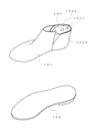
- FIG. 2 is a diagram showing a wooden pattern before the upper is attached, a wooden pattern on which the upper is attached, and a shoe sole adhered to the underside of the upper.
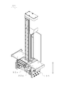
- the adhesive application device 1 for applying the adhesive to the upper 101 which is a part constituting the shoe, has the input portion 2, the coating portion 3, and the delivery portion 4 from the left side when viewed from the A direction. Is arranged so as to surround the circumference of the industrial robot 5, and the industrial robot 5 conveys the upper 101 in the order of the input portion 2, the coating portion 3, and the delivery portion 4. Then, in the delivery section 4, the upper 101 is separated from the industrial robot 5 and conveyed to the drying furnace 7 by the belt conveyor 6. Further, the input section 2, the coating section 3, the delivery section 4, and the industrial robot 5 are surrounded by a safety fence 8.
- the upper 101 is attached to the wooden mold 102, an adhesive is applied to the periphery of the bottom, and the shoe sole 103 is fixed by adhesion.
- the wooden mold 102 is provided with two holes 102b and 102c, a deep first hole 102b and a second hole 102c in a portion exposed from the upper 101 (upper surface 102a of the wooden mold 102).
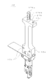
- the upper 101 is made of leather, for example, and is attached to the wooden mold 102, and is coupled to the jig 12 (chuck block) set at a predetermined position in the loading unit 2.
- the jig 12 has a main body portion 12a, a fitting rod 12b provided above the main body portion 12a and inserted into holes 102b and 102c of the wooden mold 102, and a fitting pin 12c.
- the fitting rod 12b has a rod 12ba having an enormous tip portion inserted therein so as to be displaceable.
- a portion 12bb that swells radially outward in the radial direction is formed near the tip of the outer peripheral portion, and the bulging portion 12bb is formed by displacing the tip (expansion portion) of the rod 12ba downward. Is mechanically bulging outward in the radial direction. Therefore, since the fitting rod 12b and the fitting pin 12c are set so as to protrude upward in the loading portion 2, the operator can use the fitting rod 12b and the fitting pin 12c as a wooden mold.
- the rod 12ba By pushing into the fitting holes 102b and 102c of 102, the rod 12ba is displaced downward, the swelling portion 12bb is inflated radially, and the fitting rod 12b is joined so as not to come off from the wooden mold 102, and the upper 101 (wooden mold). 102) will be firmly bonded to the jig 12.
- the fitting of the hole 102c and the fitting pin 12c is for preventing rotation.
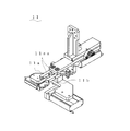
- the jig 12 is gripped by the robot hand portion 11 (see FIG. 4) provided at the tip of the robot arm of the industrial robot 5, and the upper 101 is conveyed to the coating portion 3 together with the wooden mold 102.
- the robot hand portion 11 has left and right gripping arms 11a and 11b that are displaced so as to be openable and closable via a link mechanism, and is provided on the gripping surface portion of one gripping arm 11a at the lower portion of the main body portion 12a of the jig 12.
- a pair of engaging pins 11aa and 11aa that engage with the engaging holes 12d and 12d project.
- the robot hand unit 11 conveys the upper 101 together with the wooden mold 102 from the charging unit 2 to the coating unit 3.
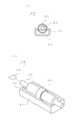
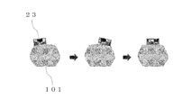
- a coating device 24 including a coating roller 23 for coating is installed on the peripheral edge of the bottom portion of the surface.
- the coating device 24 further includes a rotation driving device 26 that rotationally drives the rotating shaft 25, and the coating roller 23 is fixed to the rotating shaft 25.
- the coating roller 23 has a narrow width so that it can be easily applied to the lower peripheral edge of the upper 101.
- the movement of the robot hand unit 11 is controlled by the control device 5A of the industrial robot 5, and the lower peripheral edge of the upper 101 is rotated in order while changing the direction of the upper 101 gripped by the robot hand unit 11.
- the coating is performed in the coating portion 3 by moving the coating roller 23 while pressing it so as to contact the upper portion of the coating roller 23. Therefore, fine parts can be applied and the adhesive does not fall.
- the upper 101 is conveyed to the delivery portion 4, and the upper 101 is separated from the jig 12.
- the jig 12 is returned to the charging unit 2 and set in a predetermined state.
- a disconnection device 31 for disconnecting the upper 101 from the jig 12 is arranged in the delivery portion 4.
- the disconnection device 31 has a grip portion 32 that can be raised and lowered, and the grip portion 32 is provided with cylinder rods 32a, 32a, ... Of a plurality of air cylinders.
- This air cylinder is in a state of expansion and contraction free when air is supplied.
- the grip portion is closed when the upper 101 is brought by the moving means 5 at the center of the grip portion 32, the cylinder rods 32a of the air cylinder stop at positions in contact with the upper 101, respectively.
- the cylinder rod 32a of the air cylinder is fixed in the same position, and the grip portion 32 grips the upper 101 gripped by the robot hand portion 11 in the upper position.
- the moving means 5 lowers the grip portion 32 of the jig to separate the upper 101 (wooden mold 102) from the jig 12, and only the upper 101 remains in the grip portion 32.
- the grip portion 32 is lowered, and the upper 101 is lowered on the belt conveyor 6 installed below.
- the upper 101 is automatically conveyed to the dryer 7 (for example, 60 ° C.) by the belt conveyor 6 and dried for a predetermined time.
- the bottom portion (three-dimensional shape) of the upper 101 in the installed state is photographed by the camera 41 (for example, Intel RealSense Depth Camera D415) which is the photographing means arranged in the upper part of the input portion 2.
- the camera 41 for example, Intel RealSense Depth Camera D415.
- the image processing unit 5Aa of the control device 5A of the industrial robot 5 Upon receiving the signal from the camera 41, the image processing unit 5Aa of the control device 5A of the industrial robot 5 performs image processing, and based on the processing result, the bottom peripheral edge detection unit 5Ab requires coating of the upper 101.
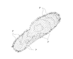
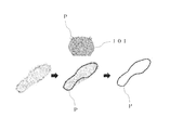
- the three-dimensional shape of the bottom peripheral edge of the robot is detected as a three-dimensional image (3D image) (see FIG. 7).
- P each point or a line segment in which they are gathered
- P each point or a line segment in which they are gathered
- the contour line of the upper 101 that moves the edge of the coating roller 23 is detected as a line segment P in the three-dimensional space (see FIG. 8).
- the three-dimensional shape of the upper 101 obtained by the camera 41 includes the bottom surface of the upper bottom and the three-dimensional shape of the side surface of the upper bottom. That is, it is the range captured from the upper camera 41, and includes the position of the maximum width of the bottom surface and the side surface as seen from above. Since the slope of the bottom surface of the upper is gentle and the slope of the side surface is steep, the contour line of the bottom peripheral edge can be detected by paying attention to the portion where the slope changes. In this way, the contour line in the cross section in the width direction shown in FIG. 8 is extracted. If the line segment P on the three-dimensional space is the three-dimensional information of the position, the inclination information of the bottom portion in contact with the contour line can be obtained at that time (see FIG. 7).
- the operation command value of the moving means 5 is determined so that the edge of the roller 23 of the coating device 24 hits the contour line of the bottom peripheral edge. That is, from the toe of the upper 101 toward the heel so that the right edge of the roller 23 hits the right half of the upper 101 and the left edge of the roller 23 hits the left half of the upper 101. Determines the rollers to move relatively.
- the operation command of the moving means 5 is determined so that the upper 101 moves relative to the fixed roller 23. Further, when the bottom of the upper 101 is wide, a place where the adhesive is not applied remains in the center of the bottom. In that case, an operation command for the roller 23 to be in the center is also added. As for how to hit the roller 23, as shown in FIG. 9, the operation command value of the moving means 5 is determined so that the roller 23 hits according to the inclination of the bottom of the upper 101.
- the operation command value of the moving means 5 created by the operation command creating unit of 5Ad is only the operation portion in which the upper 101 is applied to the roller 23, the remaining operation command value of the moving means 5 is a general operation command value of an industrial robot. It is created by the method and stored in the memory unit of 5Ac.
- the robot hand portion 11 detachably grips the jig 12 in which the upper 101 is set.
- the upper 101 is conveyed to the coating unit 3 while being gripped by the robot hand unit 11, and the coating roller 23 is moved so that the lower peripheral edge of the upper 101 comes into contact with the upper portion of the coating roller 23 based on the operation command value. Press against to perform the coating operation.
- the upper 101 is moved to the coating roller 23 installed at a fixed position, and the adhesive 22 is applied along the contour line of the left half of the bottom peripheral edge.
- the upper 101 is moved and the adhesive 22 is applied along the contour line of the right half of the bottom peripheral edge. If the bottom of the upper 101 is wide and there is a place where the adhesive is not applied in the center, the upper 101 is moved and the adhesive 22 is applied to the center of the peripheral edge of the bottom.
- the upper 101 is moved so that the edge of the coating roller 23 moves along the contour line of the upper 101, and the adhesive 22 is applied so as not to protrude from the contour line of the upper 101. Since the coating roller 23 is rotated, the adhesive 22 is lifted, the adhesive 22 is always held on the outer peripheral surface, and the adhesive 22 in the storage box 21 is agitated, so that the adhesive may harden. Be prevented.
- the upper 101 is conveyed to the delivery section 4 where the delivery device 31 is arranged. Then, at the upper position of the delivery portion 4, the upper 101 is gripped from both sides by the cylinder rods 32a and 32a of the air cylinder of the grip portion 32, and the air is stopped to lock the grip. In that state, in order to release the lock by the first fitting rod 12b of the jig 12, the jig 12 is raised by the robot 5, the jig 12 is pulled out from the upper 101, and the jig 12 is removed from the upper 101. Open.
- the grip portion 32 in the state of gripping the upper 101 descends to the vicinity of the belt conveyor 6 to the dryer 7, lowers the upper 101 onto the belt conveyor 6 at the right timing, unlocks the air cylinder, and releases the cylinder rod.
- the gripping at 32a and 32a is released.
- the upper 101 and the shoe sole 103 are firmly adhered to each other by being conveyed to the dryer 7 by the belt conveyor 6 and dried by the dryer 7.
- the opened jig 12 is conveyed to the loading unit 2 by the robot 5 and set at a predetermined position.
- the upper 101 is set on the jig 12 (step S1), and the three-dimensional shape of the upper 101 is acquired as a 3D image (step S2).
- An operation command value is created (step S3).
- the industrial robot 5 performs a coating operation based on the operation command value (step S4), and after the coating is completed, the robot 5 is charged into the dryer 7 (step S5).
- a typical operation command value for one pair may be created.
- the typical operation command value of one pair is stored in the memory, and for shoes of the same type and size, only the misalignment when the jig is attached is corrected, and the basic operation command value is corrected and used. ..
- the basic operation command value can be corrected and used. That is, since the left and right shoes are symmetrical, the elements in the X direction may be reversed, and since there is a rule (grading) in the size difference, each dimension is increased or decreased by a predetermined amount to correct the operation command value. It is possible.
- step S2 after acquiring a 3D image of one pair of measurement targets (step S2), it is determined whether or not the shoe is new (step SX), and if it is not new, it is determined.
- the basic operation command value stored in advance is corrected (step SY), and the subsequent robot coating operation (step S4) is performed.
- step SY the subsequent robot coating operation
- step S4 a new operation command value may be created from the acquired 3D image.
- the type of shoes can be used when multiple shoes of the same type and size are applied. By inputting the left and right feet and size, it is possible to quickly and continuously apply adhesive to multiple shoes.
- the coating means may be changed to a brush with hardened hair, a sponge or the like instead of the coating roller, and the adhesive may be applied.
- the coating means side may be moved.
- the robot may directly grip the upper without using a wooden mold or a jig.
- a buffing means in addition to the adhesive application device 24. This makes it possible to automatically buff the adhesive before applying it, in addition to applying the adhesive. Further, instead of the coating device 24 for applying the adhesive, a buffing device can be arranged and used as the buffing device.
Landscapes
- Footwear And Its Accessory, Manufacturing Method And Apparatuses (AREA)
- Coating Apparatus (AREA)
Abstract
Le problème décrit par la présente invention consiste à revêtir le bord périphérique inférieur d'une tige tout en déplaçant la tige par rapport à un rouleau de revêtement d'agent adhésif, de sorte qu'il est possible de revêtir de fines zones sans risque de chute de l'agent adhésif. À cet effet, le dispositif de revêtement d'agent adhésif (1) recouvre un agent adhésif (22) sur le bord périphérique inférieur d'un ensemble de tige (101) dans un modèle en bois (102). Un rouleau de revêtement (23) est disposé de manière rotative sur la partie supérieure d'une boîte de stockage d'agent adhésif (21). La forme tridimensionnelle du bord périphérique inférieur de la tige (101) dans un état monté est acquise, et le fonctionnement d'une main de robot (11) d'un robot industriel (5) est commandée sur la base de la forme tridimensionnelle pour déplacer la tige (101), qui est saisie par la main de robot (11), de telle sorte que le bord périphérique inférieur de la tige entre en contact avec la surface périphérique externe du rouleau de revêtement (23).
Priority Applications (2)
| Application Number | Priority Date | Filing Date | Title |
|---|---|---|---|
| JP2019519013A JP6664768B1 (ja) | 2019-03-12 | 2019-03-12 | 接着剤塗布装置及び接着剤塗布方法 |
| PCT/JP2019/010085 WO2020183621A1 (fr) | 2019-03-12 | 2019-03-12 | Dispositif et procédé de revêtement d'adhésif |
Applications Claiming Priority (1)
| Application Number | Priority Date | Filing Date | Title |
|---|---|---|---|
| PCT/JP2019/010085 WO2020183621A1 (fr) | 2019-03-12 | 2019-03-12 | Dispositif et procédé de revêtement d'adhésif |
Publications (1)
| Publication Number | Publication Date |
|---|---|
| WO2020183621A1 true WO2020183621A1 (fr) | 2020-09-17 |
Family
ID=70000389
Family Applications (1)
| Application Number | Title | Priority Date | Filing Date |
|---|---|---|---|
| PCT/JP2019/010085 Ceased WO2020183621A1 (fr) | 2019-03-12 | 2019-03-12 | Dispositif et procédé de revêtement d'adhésif |
Country Status (2)
| Country | Link |
|---|---|
| JP (1) | JP6664768B1 (fr) |
| WO (1) | WO2020183621A1 (fr) |
Cited By (2)
| Publication number | Priority date | Publication date | Assignee | Title |
|---|---|---|---|---|
| EP3854251A4 (fr) * | 2019-11-26 | 2022-06-15 | ASICS Corporation | Système de traitement de chaussure et procédé de commande d'un système de traitement de chaussure |
| WO2025134435A1 (fr) * | 2023-12-22 | 2025-06-26 | 株式会社アシックス | Procédé d'aide au traitement de chaussure, dispositif d'aide au traitement de chaussure et programme d'aide au traitement de chaussure |
Families Citing this family (1)
| Publication number | Priority date | Publication date | Assignee | Title |
|---|---|---|---|---|
| WO2022091212A1 (fr) * | 2020-10-27 | 2022-05-05 | 株式会社アシックス | Dispositif et procédé d'apprentissage de région de revêtement, et dispositif et procédé de prédiction de région de revêtement |
Citations (16)
| Publication number | Priority date | Publication date | Assignee | Title |
|---|---|---|---|---|
| US3722466A (en) * | 1971-07-14 | 1973-03-27 | I Brod | Apparatus for applying an adhesive on upper margin of a shoe upper |
| JPS4955454A (fr) * | 1972-02-18 | 1974-05-29 | ||
| JPS5416139B1 (fr) * | 1969-12-01 | 1979-06-20 | ||
| JPS60190901A (ja) * | 1984-03-12 | 1985-09-28 | スタ−ラバ−工業株式会社 | 物品の加工方法 |
| JPS6384503A (ja) * | 1986-09-30 | 1988-04-15 | ロジエ・ブランク | 履物製造用型 |
| JPS6371709U (fr) * | 1986-10-30 | 1988-05-13 | ||
| JPH0543363B2 (fr) * | 1984-05-21 | 1993-07-01 | Int Shoe Machine Corp | |
| JPH0585296B2 (fr) * | 1988-01-25 | 1993-12-07 | Kosmek Kk | |
| JPH0722524B2 (ja) * | 1988-05-04 | 1995-03-15 | クレツクネル・フエロマテイク・デスマ・ゲゼルシヤフト・ミツト・ベシユレンクテル・ハフツング | 靴本体にソールを一体成形するための方法及びこの方法を実施するための装置 |
| JP2530493Y2 (ja) * | 1991-06-07 | 1997-03-26 | ミドリ安全工業株式会社 | 靴型保持装置 |
| JP2002328008A (ja) * | 2001-04-27 | 2002-11-15 | Nippon Signal Co Ltd:The | 寸法測定方法及び寸法測定システム |
| JP4954899B2 (ja) * | 2005-12-27 | 2012-06-20 | 株式会社コスメック | 位置決め装置および位置決めシステム |
| US20130132038A1 (en) * | 2011-11-18 | 2013-05-23 | Nike, Inc. | Automated 3-D Modeling Of Shoe Parts |
| JP2013226519A (ja) * | 2012-04-26 | 2013-11-07 | Fanuc Ltd | ロボット塗布システム |
| JP2016171969A (ja) * | 2015-03-18 | 2016-09-29 | カシオ計算機株式会社 | 描画装置及び爪傾き検出方法 |
| GB2547693A (en) * | 2016-02-26 | 2017-08-30 | C & J Clark Int Ltd | Perforated articles and manufacture thereof |
Family Cites Families (10)
| Publication number | Priority date | Publication date | Assignee | Title |
|---|---|---|---|---|
| JPS59150558U (ja) * | 1983-03-23 | 1984-10-08 | 丸山 倶美 | 接着剤、塗料等の塗布装置 |
| JPS6068801A (ja) * | 1983-09-26 | 1985-04-19 | リ−ダ−株式会社 | 製靴用機械の制御方式 |
| GB9109891D0 (en) * | 1991-05-08 | 1991-07-03 | British United Shoe Machinery | Apparatus for operating progressively along selected portions of shoe uppers |
| DE102005033972A1 (de) * | 2005-07-20 | 2007-01-25 | Dürr Systems GmbH | Beschichtungsverfahren und zugehörige Beschichtungseinrichtung |
| US8662008B2 (en) * | 2008-02-07 | 2014-03-04 | Sunpower Corporation | Edge coating apparatus for solar cell substrates |
| JP6122125B2 (ja) * | 2013-08-22 | 2017-04-26 | 株式会社アシックス | 塗布装置、塗布剤塗布方法および塗布システム |
| EP2932866A1 (fr) * | 2014-04-08 | 2015-10-21 | AUTEC di Geri Ing. Fabrizio & C. S.A.S. | Procédé pour la peinture de parties de chaussures |
| CN108135331A (zh) * | 2015-09-03 | 2018-06-08 | 株式会社安川电机 | 鞋用粘接剂涂敷系统、涂敷轨迹生成装置以及鞋制造方法 |
| ITUB20160922A1 (it) * | 2016-02-22 | 2017-08-22 | Varnish Tech S R L | Impianto e metodo di verniciatura. |
| TWI682813B (zh) * | 2016-11-29 | 2020-01-21 | 荷蘭商耐克創新有限合夥公司 | 多噴嘴工具以及使用多噴嘴工具塗覆材料的方法 |
-
2019
- 2019-03-12 JP JP2019519013A patent/JP6664768B1/ja active Active
- 2019-03-12 WO PCT/JP2019/010085 patent/WO2020183621A1/fr not_active Ceased
Patent Citations (16)
| Publication number | Priority date | Publication date | Assignee | Title |
|---|---|---|---|---|
| JPS5416139B1 (fr) * | 1969-12-01 | 1979-06-20 | ||
| US3722466A (en) * | 1971-07-14 | 1973-03-27 | I Brod | Apparatus for applying an adhesive on upper margin of a shoe upper |
| JPS4955454A (fr) * | 1972-02-18 | 1974-05-29 | ||
| JPS60190901A (ja) * | 1984-03-12 | 1985-09-28 | スタ−ラバ−工業株式会社 | 物品の加工方法 |
| JPH0543363B2 (fr) * | 1984-05-21 | 1993-07-01 | Int Shoe Machine Corp | |
| JPS6384503A (ja) * | 1986-09-30 | 1988-04-15 | ロジエ・ブランク | 履物製造用型 |
| JPS6371709U (fr) * | 1986-10-30 | 1988-05-13 | ||
| JPH0585296B2 (fr) * | 1988-01-25 | 1993-12-07 | Kosmek Kk | |
| JPH0722524B2 (ja) * | 1988-05-04 | 1995-03-15 | クレツクネル・フエロマテイク・デスマ・ゲゼルシヤフト・ミツト・ベシユレンクテル・ハフツング | 靴本体にソールを一体成形するための方法及びこの方法を実施するための装置 |
| JP2530493Y2 (ja) * | 1991-06-07 | 1997-03-26 | ミドリ安全工業株式会社 | 靴型保持装置 |
| JP2002328008A (ja) * | 2001-04-27 | 2002-11-15 | Nippon Signal Co Ltd:The | 寸法測定方法及び寸法測定システム |
| JP4954899B2 (ja) * | 2005-12-27 | 2012-06-20 | 株式会社コスメック | 位置決め装置および位置決めシステム |
| US20130132038A1 (en) * | 2011-11-18 | 2013-05-23 | Nike, Inc. | Automated 3-D Modeling Of Shoe Parts |
| JP2013226519A (ja) * | 2012-04-26 | 2013-11-07 | Fanuc Ltd | ロボット塗布システム |
| JP2016171969A (ja) * | 2015-03-18 | 2016-09-29 | カシオ計算機株式会社 | 描画装置及び爪傾き検出方法 |
| GB2547693A (en) * | 2016-02-26 | 2017-08-30 | C & J Clark Int Ltd | Perforated articles and manufacture thereof |
Cited By (3)
| Publication number | Priority date | Publication date | Assignee | Title |
|---|---|---|---|---|
| EP3854251A4 (fr) * | 2019-11-26 | 2022-06-15 | ASICS Corporation | Système de traitement de chaussure et procédé de commande d'un système de traitement de chaussure |
| US12114736B2 (en) | 2019-11-26 | 2024-10-15 | Asics Corporation | Shoe manufacturing system and method of controlling shoe manufacturing system |
| WO2025134435A1 (fr) * | 2023-12-22 | 2025-06-26 | 株式会社アシックス | Procédé d'aide au traitement de chaussure, dispositif d'aide au traitement de chaussure et programme d'aide au traitement de chaussure |
Also Published As
| Publication number | Publication date |
|---|---|
| JPWO2020183621A1 (ja) | 2021-03-18 |
| JP6664768B1 (ja) | 2020-03-13 |
Similar Documents
| Publication | Publication Date | Title |
|---|---|---|
| CN204735367U (zh) | 用于给鞋的鞋底部分喷涂的喷涂系统 | |
| WO2020183621A1 (fr) | Dispositif et procédé de revêtement d'adhésif | |
| US11422526B2 (en) | Automated manufacturing of shoe parts | |
| EP3939466B1 (fr) | Assemblage et piqûre automatisés de pièces de chaussure | |
| EP3068250B1 (fr) | Support pour un element de semelle de chaussure | |
| CA1113664A (fr) | Installation pour la production de chaussures | |
| CN205696058U (zh) | 材料处理系统和用于以自动化方式制造鞋部件的系统 | |
| US10492570B2 (en) | Adjustable surface for use in manufacturing shoe parts | |
| US2731668A (en) | Dipping machine for forming rubber articles | |
| TW201517830A (zh) | 鞋底鞋面自動上膠方法 | |
| JP2003051532A (ja) | 両面研磨機へのウエハ結晶体の自動装填方法およびその装置 | |
| ITMC990097A1 (it) | Linea automatizzata per l'incollaggio, l'aspirazione, l'essicazione ela riattivazione del collante su semilavorati delle calzature. | |
| IT201600098965A1 (it) | Metodo per l’esecuzione di lavorazioni laser su fondi di calzature | |
| JPH06335405A (ja) | 靴製造装置 | |
| CS277039B6 (cs) | Zařízení pro ustavení textilní pásky k jejímu přímému navulkanizování na obvod podešve | |
| JPS61257602A (ja) | 靴の踵の研磨方法とその装置 | |
| ITMC990070A1 (it) | Apparato per la timbratura automatica delle solette, o altri particolari non rigidi utilizzati nelle imprese della calzatura, pelletteria ed |
Legal Events
| Date | Code | Title | Description |
|---|---|---|---|
| ENP | Entry into the national phase |
Ref document number: 2019519013 Country of ref document: JP Kind code of ref document: A |
|
| 121 | Ep: the epo has been informed by wipo that ep was designated in this application |
Ref document number: 19919316 Country of ref document: EP Kind code of ref document: A1 |
|
| NENP | Non-entry into the national phase |
Ref country code: DE |
|
| 122 | Ep: pct application non-entry in european phase |
Ref document number: 19919316 Country of ref document: EP Kind code of ref document: A1 |