WO2020183673A1 - Instrument de traitement et procédé de fabrication d'un instrument de traitement - Google Patents
Instrument de traitement et procédé de fabrication d'un instrument de traitement Download PDFInfo
- Publication number
- WO2020183673A1 WO2020183673A1 PCT/JP2019/010382 JP2019010382W WO2020183673A1 WO 2020183673 A1 WO2020183673 A1 WO 2020183673A1 JP 2019010382 W JP2019010382 W JP 2019010382W WO 2020183673 A1 WO2020183673 A1 WO 2020183673A1
- Authority
- WO
- WIPO (PCT)
- Prior art keywords
- block
- treatment tool
- heater
- sheet
- seat heater
- Prior art date
- Legal status (The legal status is an assumption and is not a legal conclusion. Google has not performed a legal analysis and makes no representation as to the accuracy of the status listed.)
- Ceased
Links
Images


Classifications
-
- A—HUMAN NECESSITIES
- A61—MEDICAL OR VETERINARY SCIENCE; HYGIENE
- A61B—DIAGNOSIS; SURGERY; IDENTIFICATION
- A61B18/00—Surgical instruments, devices or methods for transferring non-mechanical forms of energy to or from the body
- A61B18/04—Surgical instruments, devices or methods for transferring non-mechanical forms of energy to or from the body by heating
- A61B18/08—Surgical instruments, devices or methods for transferring non-mechanical forms of energy to or from the body by heating by means of electrically-heated probes
Definitions
- the present invention relates to a treatment tool and a method for manufacturing the treatment tool.
- Patent Document 1 a treatment tool for treating a target site in a living tissue by applying energy to a target site (hereinafter referred to as a target site) has been known (see, for example, Patent Document 1).
- the treatment tool described in Patent Document 1 includes a pair of gripping members that grip the target portion.
- the gripping member is provided with a seat heater that generates heat when energized, and a blade that comes into contact with the target portion when the target portion is gripped by a pair of gripping members. Then, in the treatment tool, the heat of the seat heater is transferred to the target portion gripped by the pair of gripping members via the blade. As a result, the target site is treated.
- the sheet heater described in Patent Document 1 includes a substrate and a conductive portion provided on the substrate.
- the conductive portion includes first and second connecting portions to which the wiring members are electrically connected, and a heat generating portion that generates heat when energized.
- the first and second connecting portions are arranged side by side in the width direction of the substrate on the base end side of the substrate.
- the heat generating portion has a substantially U-shape extending from the proximal end side toward the distal end side, folded back on the distal end side, and extending toward the proximal end side on the substrate. Then, both ends of the heat generating portion are connected to the first and second connecting portions, respectively. That is, the conductive portion has two electric paths parallel to each other in the width direction of the substrate.
- the sheet heater described in Patent Document 1 has two electric paths arranged in parallel in the width direction of the substrate. Then, in order to prevent the two electric paths from being short-circuited, it is necessary to sufficiently separate the two electric paths. That is, there is a problem that the width dimension of the substrate becomes large.
- a seat heater having the following configuration (hereinafter, referred to as a folded seat heater).
- the conductive portion extends along the longitudinal direction of the substrate.
- the folded-back type sheet heater is folded back along the folded-back line intersecting in the longitudinal direction of the substrate with the first plate surface forming the outer surface of the folded-back type sheet heater.
- the present invention has been made in view of the above, and provides a treatment tool capable of reducing the width dimension of the substrate and preventing disconnection of the conductive portion, and a method for manufacturing the treatment tool.
- the purpose is.
- the treatment tool comprises a blade having a treatment surface for treating a living tissue, a mounting surface having a front-back relationship with the treatment surface, and electrical insulation.
- a sheet heater having a substrate made of a material having properties and a conductive portion having a heat generating portion that generates heat when energized, and the first plate surface and the second plate surface in which the substrates have a front and back relationship with each other.
- the sheet heater includes a sheet heater and a block in which the conductive portion extends along the longitudinal direction of the substrate on the first plate surface, and the sheet heater has the first plate surface.
- the outer surface of the seat heater is folded back along the folding line intersecting in the longitudinal direction, and the heat generating portion is installed so as to face the mounting surface, and the block is installed along the folding line. It is arranged inside the folded seat heater.
- the method for manufacturing the treatment tool according to the present invention includes a bonding sheet arranging step of arranging an uncured adhesive sheet on a mounting surface of a blade for treating a living tissue, and a jig mounting for attaching a press jig to a block.
- the uncured state is formed by the step, the sheet heater arranging step of arranging the sheet heater between the uncured adhesive sheet and the block, and pressing the block toward the mounting surface by the press jig.
- the present invention includes a hot pressing step of curing the uncured adhesive sheet by compressing the adhesive sheet and applying heat, and a jig removing step of removing the press jig from the block.
- the width dimension of the substrate can be reduced and the disconnection of the conductive portion can be prevented.
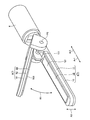
- FIG. 1 is a diagram showing a treatment system according to the first embodiment.
- FIG. 2 is a diagram showing a grip portion.
- FIG. 3 is a diagram showing a first gripping member.
- FIG. 4 is a diagram showing a first gripping member.
- FIG. 5 is a diagram showing a seat heater.
- FIG. 6 is a diagram showing a seat heater.
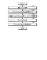
- FIG. 7 is a flowchart showing a method of manufacturing the treatment tool.
- FIG. 8 is a diagram illustrating a method for manufacturing a treatment tool.
- FIG. 9 is a diagram showing a seat heater according to the second embodiment.
- FIG. 10 is a diagram showing a seat heater according to the third embodiment.
- FIG. 11 is a diagram showing a seat heater according to the third embodiment.
- FIG. 12 is a flowchart showing a method of manufacturing the treatment tool.
- FIG. 13 is a diagram illustrating a method for manufacturing a treatment tool.
- FIG. 14 is a diagram showing a modified
- FIG. 1 is a diagram showing a treatment system 1 according to the first embodiment.
- the treatment system 1 treats a target site in a living tissue by applying energy to a target site (hereinafter referred to as a target site).
- the treatment means, for example, coagulation and incision of a target site.
- the treatment system 1 includes a treatment tool 2 and a control device 3.
- the treatment tool 2 is, for example, a surgical treatment tool for treating a target site while passing through the abdominal wall.
- the treatment tool 2 includes a handle 5, a shaft 6, and a grip portion 7.
- the handle 5 is a part held by the operator.
- the handle 5 is provided with an operation knob 51 and a switch 52.
- the operation knob 51 accepts an opening / closing operation by the operator.
- the switch 52 receives an output start operation by the operator. Then, the switch 52 outputs an operation signal corresponding to the output start operation to the control device 3 via the electric cable C (FIG. 1).
- the shaft 6 has a substantially cylindrical shape.
- the central axis of the shaft 6 will be referred to as the central axis Ax (FIG. 1).
- one side along the central axis Ax will be referred to as the distal end side Ar1 (FIG. 1), and the other side will be referred to as the proximal end side Ar2 (FIG. 1).
- the end of the base end side Ar2 of the shaft 6 is connected to the handle 5.
- a grip portion 7 is attached to the end portion of the tip end side Ar1 of the shaft 6. Then, inside the shaft 6, an opening / closing mechanism for opening / closing the first and second gripping members 8 and 9 (FIG.
- FIG. 2 is a diagram showing a grip portion 7.
- the grip portion 7 is a portion that treats the target portion while gripping the target portion.
- the grip portion 7 includes first and second grip members 8 and 9.
- the first and second gripping members 8 and 9 are configured to be openable and closable in the direction of arrow R1 (FIG. 2) in response to an opening and closing operation of the operation knob 51 by the operator.
- FIGS. 3 and 4 are views showing the first gripping member 8.
- FIG. 3 is a cross-sectional view of the first gripping member 8 cut by a plane including the central axis Ax.
- FIG. 4 is a cross-sectional view of the first gripping member 8 cut along a plane orthogonal to the central axis Ax.
- the first gripping member 8 is arranged at a position facing the second gripping member 9.
- the first gripping member 8 includes a first jaw 10, a first support member 11, a blade 12, a seat heater 13 (FIGS. 3 and 4), and the like.
- a block 14 (FIGS. 3 and 4) is provided.
- the first jaw 10 is a portion in which a part of the shaft 6 extends to the tip end side Ar1, and is formed in a long shape extending along the central axis Ax.
- the first jaw 10 is made of a metal material such as a stainless alloy or a titanium alloy.
- the first support member 11 has an elongated shape extending along the central axis Ax, and is fixed to the upper surface in FIGS. 3 and 4 of the first jaw 10.
- a recess 111 extending from the base end of the first support member 11 toward the tip end side Ar1 is formed on the upper surface in FIGS. 3 and 4. .
- the first support member 11 supports the blade 12, the seat heater 13, and the block 14 in the recess 111.
- a resin material having electrical insulation such as PEEK (polyetheretherketone) and having a low thermal conductivity can be exemplified. That is, by disposing the first support member 11 having a low thermal conductivity between the blade 12 and the seat heater 13 and the first jaw 10, heat is transferred from the seat heater 13 to the first jaw 10. It is possible to efficiently transfer the heat from the seat heater 13 to the blade 12.
- PEEK polyetheretherketone
- the blade 12 has an elongated shape extending along the central axis Ax and is fixed in the recess 111.
- the blade 12 is made of a material having conductivity and excellent thermal conductivity, such as copper, aluminum, a copper alloy, and an aluminum alloy.
- the upper surface in FIGS. 3 and 4 comes into contact with the target portion while the target portion is gripped by the first and second gripping members 8 and 9. That is, the surface functions as a treatment surface 121 (FIGS. 2 to 4) for treating the target site.
- the treatment surface 121 has a direction A1 (in which the first and second gripping members 8 and 9 face each other in a state where the target portion is gripped by the first and second gripping members 8 and 9).
- the treatment surface 121 is formed of a flat surface, but the treatment surface 121 is not limited to this, and may be formed of other shapes such as a convex shape and a concave shape. The same applies to the gripping surface 931 described later in the second gripping member 9.
- a recess 123 (FIGS. 3 and 4) extending from the base end to the tip of the blade 12 is formed on the mounting surface 122 having a front-back relationship with the treatment surface 121. Then, the blade 12 supports the seat heater 13 and the block 14 by the bottom surface of the recess 123.
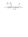
- FIG. 5 and 6 are views showing the seat heater 13. Specifically, FIG. 5 is a view of the state before the seat heater 13 is folded back as viewed from the first plate surface 150a side of the substrate 15.
- FIG. 6 is a cross-sectional view of the state after the seat heater 13 is folded back, cut by a plane orthogonal to the width direction (left-right direction in FIG. 4) of the seat heater 13. Note that, in FIG. 6, the block 14 is also shown for convenience of explanation. A part of the seat heater 13 generates heat when energized. As shown in FIG. 5 or 6, the sheet heater 13 includes a substrate 15 and a conductive portion 16.
- the substrate 15 is a sheet-shaped flexible substrate made of a resin material having electrical insulation such as polyimide.
- the substrate 15 is formed in a long shape, and has first and second wide portions 151 and 152 located at both ends in the longitudinal direction (left-right direction in FIG. 5), and the first and second wide portions. It is located between 151 and 152, and includes a narrow portion 153 that connects the first and second wide portions 151 and 152.
- the width dimension (length dimension in the vertical direction in FIG. 4) of the narrow portion 153 is set substantially uniformly along the longitudinal direction of the substrate 15. Further, the width dimension of the narrow portion 153 is set to be smaller than that of the first and second wide portions 151 and 152.
- the conductive portion 16 is vapor-deposited on the first plate surface 150a of the first plate surface 150a (FIGS. 5 and 6) and the second plate surface 150b (FIG. 6) having a front-back relationship with each other on the substrate 15. It is formed by patterning a metal thin film formed by or sputtering with photolithography. As shown in FIG. 5 or 6, the conductive portion 16 includes first and second connecting portions 161, 162, a heat generating portion 163, and an electric path portion 164.
- the first connecting portion 161 is located at the right end portion (corresponding to the first end according to the present invention) of the conductive portion 16 in FIG. 5, and is provided in the first wide portion 151. Has been done. Then, the first lead wire C1 (FIG. 6) constituting the electric cable C is electrically connected to the first connecting portion 161.
- the first lead wire C1 corresponds to the first wiring member according to the present invention.
- the second connecting portion 162 is located at the left end portion (corresponding to the second end according to the present invention) of the conductive portion 16 in FIG. 5, and is provided in the second wide portion 152. Has been done. Then, the second lead wire C2 (FIG. 6) constituting the electric cable C is electrically connected to the second connecting portion 162.
- the second lead wire C2 corresponds to the second wiring member according to the present invention.
- the heat generating portion 163 is connected to the first connecting portion 161 and the other end side extends toward the second connecting portion 162 side while meandering in a wavy shape, for example.
- the heat generating portion 163 is not limited to a shape that extends while meandering in a wavy shape, and may have a shape that extends linearly from the first connecting portion 161 toward the second connecting portion 162 side.
- the electric path portion 164 is a portion that serves as an energizing path between the second connecting portion 162 and the heat generating portion 163. That is, one end of the electric path portion 164 is connected to the other end of the heat generating portion 163.
- the end portion on the one end side will be referred to as the heat generation side end portion 164a (FIGS. 5 and 6).
- the electric path portion 164 extends linearly from the heat generating side end portion 164a toward the second connecting portion 162 side, and the other end is connected to the second connecting portion 162.
- the conductive portion 16 extends along the longitudinal direction of the substrate 15 on the first plate surface 150a. More specifically, the conductive portion 16 is connected in series in the order of the first connecting portion 161, the heat generating portion 163, the electric path portion 164, and the second connecting portion 162 along the longitudinal direction of the substrate 15. It is provided on the first plate surface 150a.
- the resistance value of the heat generating portion 163 is set to the first and second connecting portions 161, 162, the heating portion 163, and the electric path portion 164 to have a predetermined total length and cross-sectional area, respectively. It is set higher than the connection portions 161, 162 and the electric path portion 164 of the above. Specifically, the first and second connecting portions 161, 162 and the electric path portion 164 have a larger cross-sectional area than the heat generating portion 163. Therefore, when a voltage is applied to the first and second connection portions 161, 162 by passing through the first and second lead wires C1 and C2 under the control of the control device 3, heat is generated. Part 163 mainly generates heat.
- the sheet heater 13 described above is fixed to the bottom surface of the recess 123 by the adhesive sheet 17 (FIGS. 3 and 4) in a folded state.
- the adhesive sheet 17 is located between the bottom surface of the recess 123 and the sheet heater 13, and adheres the bottom surface and the sheet heater 13.
- the adhesive sheet 17 is formed by mixing a material having high thermal conductivity, high temperature resistance, and adhesiveness, for example, epoxy resin, with a ceramic having high thermal conductivity such as alumina and aluminum nitride. Has been done.
- the seat heater 13 is folded back so as to be orthogonal to the longitudinal direction of the substrate 15 and located substantially in the center of the longitudinal direction in a state where the first plate surface 150a constitutes the outer surface of the seat heater 13.
- the folding line Ln is not limited to a line Ln that is exactly orthogonal to the longitudinal direction of the substrate 15, but also includes a line that intersects the longitudinal direction within a predetermined angle range.
- the region on the first connecting portion 161 side with respect to the folding line Ln is referred to as the treatment side region Sp1
- the region on the second connecting portion 162 side with respect to the folding line Ln is referred to as the back side region Sp2.
- the electric path portion 164 is provided so as to straddle the turnaround line Ln. Therefore, the first connecting portion 161, the heat generating portion 163, and the heat generating side end portion 164a are located in the treatment side region Sp1. Further, in the back surface side region Sp2, the second connecting portion 162 and the region of the electric path portion 164 other than the heat generating side end portion 164a are located. Then, the sheet heater 13 is folded back along the folding line Ln as described above, and is fixed to the bottom surface by the adhesive sheet 17 in a state where the treatment side region Sp1 faces the bottom surface of the recess 123.
- the block 14 is a long flat plate extending along the central axis Ax, and is arranged inside the folded seat heater 13 as shown in FIG. Then, the block 14 prevents the conductive portion 16 from being disconnected at the folded portion of the seat heater 13.
- the end face of the distal end side Ar1 is formed by a curved surface 141 having a specific radius of curvature and whose center of curvature is parallel to the folding line Ln. Then, as shown in FIG. 6, the curved surface 141 abuts on the folded portion of the seat heater 13. By making the radius of curvature of the curved surface 141 as large as possible within the heater mounting region, disconnection can be prevented.
- the radius of curvature can be, for example, in the range of about 0.2 to 0.6 mm.
- the block 14 extends from the curved surface 141 toward the proximal end side Ar2 to a position facing the first connecting portion 161. Then, each part of the first and second connecting portions 161 and 162 (first and second wide portions 151 and 152) is in a state of projecting from the block 14 to the proximal end side Ar2, respectively.
- a material having electrical insulation and heat resistance is preferable, and a resin material such as PEEK, ceramic or the like can be exemplified.
- the upper surface of the block 14 in FIG. 6 is referred to as a pressing surface 142
- the lower surface of the block 14 in FIG. 6 is referred to as a back surface 143
- the base end side of the block 14 is described.
- the surface of Ar2 is referred to as a base end surface 144.
- the second gripping member 9 includes a second jaw 91, a second support member 92, and a facing plate 93.
- the second jaw 91 has an elongated shape extending along the central axis Ax. Then, in the second jaw 91, the end portion of the base end side Ar2 is rotatably supported with respect to the shaft 6 about the fulcrum P0 (FIG. 2), and by rotating, the first gripping member 8 Opens and closes against.
- the first gripping member 8 is fixed to the shaft 6, and the second gripping member 9 is pivotally supported by the shaft 6, but the present invention is not limited to this.
- a configuration may be adopted in which both the first and second gripping members 8 and 9 are pivotally supported by the shaft 6 and the first and second gripping members 8 and 9 are opened and closed by rotating each of them. Absent. Further, for example, the first gripping member 8 is pivotally supported by the shaft 6, the second gripping member 9 is fixed to the shaft 6, and the first gripping member 8 rotates to the second gripping member 9. On the other hand, a configuration that opens and closes may be adopted.
- the second support member 92 is made of a resin material having electrical insulation such as PEEK and having a low thermal conductivity, and is arranged between the second jaw 91 and the facing plate 93. ing.
- the facing plate 93 is made of a conductive material such as copper, and is fixed on a surface of the second supporting member 92 facing the first gripping member 8. In the facing plate 93, the surface on the side of the first gripping member 8 functions as a gripping surface 931 (FIG. 2) for gripping the target portion with the treatment surface 121.
- Control device configuration The treatment tool 2 is detachably connected to the control device 3 by the electric cable C. Then, the control device 3 is electrically connected to the switch 52 via the electric cable C. Further, the control device 3 is electrically connected to the conductive portion 16 via the electric cables C (first and second lead wires C1 and C2). Further, the control device 3 is electrically connected to the blade 12 and the facing plate 93, respectively, via the electric cable C. Then, the control device 3 executes the following treatment control in response to the operation signal from the switch 52.
- the control device 3 applies a voltage to the first and second connection portions 161, 162 by passing through the first and second lead wires C1 and C2.
- the control device 3 measures the resistance value of the conductive portion 16 (hereinafter referred to as heater resistance) from the voltage value and the current value supplied to the conductive portion 16 by using, for example, a voltage drop method.
- the control device 3 refers to the resistance temperature characteristics measured in advance.
- the resistance temperature characteristic is a characteristic showing the relationship between the heater resistance and the temperature of the heat generating portion 163 (hereinafter, referred to as the heater temperature). Then, the control device 3 controls the heater resistance to a target resistance value corresponding to the target temperature in the resistance temperature characteristic while changing the electric power supplied to the conductive unit 16.
- the heater temperature is controlled to the target temperature.
- the heat from the heat generating portion 163 controlled to the target temperature is transferred to the target portion gripped between the first and second gripping members 8 and 9 via the blade 12. In other words, thermal energy is applied to the target portion.
- control device 3 supplies high-frequency power to the blade 12 and the facing plate 93 by passing through the electric cable C substantially at the same time as applying the thermal energy to the target portion described above.
- a high-frequency current flows through the target portion gripped between the blade 12 and the facing plate 93.
- high frequency energy is applied to the target portion.
- the blade 12 and the counter plate 93 also have a function as an electrode to which high frequency power is supplied and a high frequency current is passed to the target portion.
- the target portion is heated by the above-mentioned application of thermal energy.
- Joule heat is generated by the high frequency current flowing through the target portion.
- the target site is treated.
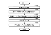
- FIG. 7 is a flowchart showing a method of manufacturing the treatment tool 2.
- FIG. 8 is a diagram illustrating a method of manufacturing the treatment tool 2. In the following, for convenience of explanation, only a method of attaching the seat heater 13 and the block 14 to the blade 12 will be described as a method of manufacturing the treatment tool 2.
- step S1 adhesive sheet arrangement step
- step S2 the operator attaches the press jig 200 to the block 14 as shown in FIGS. 8 (b) and 8 (c) (step S2: jig attaching step).
- the press jig 200 includes a jig main body 210, a first fixing portion 220, and a second fixing portion 230.
- the jig body 210 is detachably connected to the block 14. More specifically, as shown in FIG. 8 (b) or FIG. 8 (c), the back surface 143 and the base end surface 144 of the block 14 are provided with a plurality of recesses 145 (three in the first embodiment). ing.
- a plurality of locking projections 211 that are locked to the plurality of recesses 145 are provided on the outer surface of the jig main body 210. Then, the jig main body 210 is attached to the block 14 as shown below.
- the operator inserts the plurality of locking projections 211 of the jig main body 210 into the plurality of recesses 145 from the upper side in FIG. 8B with respect to the block 14, and the jig is inserted into the block 14 from the upper side.
- the main body 210 is slid to the left in FIG. 8 (b).
- the plurality of locking projections 211 are respectively locked in the plurality of recesses 145, and the jig body 210 is attached to the block 14.
- the plurality of recesses 145 are not limited to the shape shown in FIG. 8, and for example, the block 14 may have a shape that penetrates in a direction orthogonal to the paper surface of FIG.
- the operator attaches a plurality of locking projections 211 of the jig main body 210 to the plurality of recesses 145 from the side orthogonal to the paper surface of FIG. 8B (the side surface side of the block 14) with respect to the block 14. insert.
- the plurality of locking projections 211 are respectively locked in the plurality of recesses 145, and the jig body 210 is attached to the block 14.
- the first and second fixing portions 220 and 230 are detachably connected to the jig main body 210. Then, the first and second fixing portions 220 and 230 can sandwich the seat heater 13 with the jig main body 210, respectively.
- step S2 the worker performs step S2 as shown below.
- the operator attaches the jig body 210 to the block 14.
- the operator blocks the second plate surface 150b of the seat heater 13 in a state where the folding line Ln of the seat heater 13 is located on the curved surface 141 of the block 14. It comes into contact with the pressing surface 142 and the curved surface 141.
- the operator attaches the first fixing portion 220 to the jig main body 210 so that the portion of the seat heater 13 on the first wide portion 151 side is between the jig main body 210 and the first fixing portion 220. Hold it with.
- the operator attaches the second fixing portion 230 to the jig main body 210 so that the portion of the seat heater 13 on the second wide portion 152 side is between the jig main body 210 and the second fixing portion 230. Hold it with.
- the seat heater 13 is positioned with respect to the block 14 and the press jig 200 in a state of being folded back along the curved surface 141 (a state of being folded back along the folding line Ln).
- step S2 the operator moves the press jig 200 to a position where the pressing surface 142 faces the uncured adhesive sheet 17 (step S3: sheet heater arranging step). .. As a result, the sheet heater 13 is arranged between the uncured adhesive sheet 17 and the block 14.
- step S3 the operator presses (presses) the block 14 toward the bottom surface of the recess 123 with the press jig 200 to bring the uncured adhesive sheet 17 into a compressed state. Further, the operator heats the compressed unit (blade 12, sheet heater 13, block 14, and press jig 200) by putting it in a curing furnace (step S4: hot press step). As a result, the uncured adhesive sheet 17 is cured, and the adhesive sheet 17 adheres and fixes the sheet heater 13 and the pressing surface 142 of the block 14 to the bottom surface of the recess 123.
- the press device itself may be provided with a heating mechanism so that it can be heated at the same time as the press.
- step S4 the operator removes the press jig 200 from the block 14 as shown in FIG. 8 (e) (step S5: jig removal step).
- the conductive portion 16 extends along the longitudinal direction of the substrate 15 on the first plate surface 150a. Then, the seat heater 13 is folded back along the folding line Ln in a state where the first plate surface 150a constitutes the outer surface. That is, it is not necessary to parallel the two electric paths in the width direction of the substrate 15, and the width dimension of the substrate 15 can be reduced. Further, the block 14 is arranged inside the seat heater 13 folded along the folding line Ln. Therefore, the block 14 can limit the curvature of the folded portion of the seat heater 13 from becoming too small, and can prevent the conductive portion 16 from being disconnected.
- the seat heater 13 is folded back along the curved surface 141 of the block 14. Therefore, the curvature of the folded portion of the seat heater 13 can be set to be the same as the curvature of the curved surface 141. That is, the curvature of the folded portion can be set to a desired curvature, and the disconnection of the conductive portion 16 can be prevented more reliably.
- the block 14 is made of a material such as a resin having electrical insulation and heat insulation (or lower thermal conductivity than the blade 12). Further, the block 14 extends from the curved surface 141 toward the proximal end side Ar2 to a position facing the first connecting portion 161. That is, between the treatment side region Sp1 in the conductive portion 16 and the back surface side region Sp2 in the conductive portion 16, there are a substrate 15 and a block 14 having electrical insulation properties, respectively. Therefore, a sufficient creepage distance between the treatment side region Sp1 in the conductive portion 16 and the back surface region Sp2 in the conductive portion 16 can be sufficiently secured, and a short circuit occurs between the treatment side region Sp1 and the back surface region Sp2. It can be prevented from occurring.
- the block 14 is provided with a recess 145. Therefore, by making the air layer in the recess 145 function as a heat insulating layer, the heat insulating property of the block 14 can be further improved by both the heat insulating property of the material (resin or the like) of the block 14 itself and the heat insulating layer. It is possible to efficiently transfer the heat from the heat generating portion 163 to the blade 12.
- the conductive portion 16 has a first connecting portion 161, a heat generating portion 163, an electric path portion 164, and a second connecting portion along the longitudinal direction of the substrate 15. It is provided on the first plate surface 150a in a state of being connected in series in the order of 162.
- the electric path portion 164 is provided so as to straddle the turnaround line Ln. That is, in the state where the seat heater 13 is folded back along the folding line Ln, the electric path portion 164 is folded back.
- the electric path portion 164 has a larger cross-sectional area than the heat generating portion 163. Therefore, the disconnection of the conductive portion 16 can be further prevented as compared with the case where the heat generating portion 163 is folded back.
- the seat heater 13 is attached to the blade 12 as shown below. That is, after the step S1, the operator arranges the sheet heater 13 (treatment side region Sp1) on the uncured adhesive sheet 17. After that, the operator compresses the uncured adhesive sheet 17 by directly pressing the sheet heater 13 (treatment side region Sp1) toward the bottom surface of the recess 123 with a press jig, and does not apply heat. The cured adhesive sheet 17 is cured. Then, when the sheet heater 13 is attached to the blade 12 as described above, the adhesive sheet 17 may stick to the press jig. In this case, there is a problem that the seat heater 13 itself may be destroyed or damaged when the press jig is peeled off. According to the method for manufacturing the treatment tool 2 according to the first embodiment (steps S1 to S5), since the block 14 is provided, the adhesive sheet 17 does not stick to the press jig 200. That is, the above-mentioned problem does not occur.
- the seat heater 13 is positioned with respect to the block 14 and the press jig 200. Therefore, the bonding position of the seat heater 13 with respect to the blade 12 can be made constant, and the performance does not vary.
- FIG. 9 is a diagram showing the seat heater 13A according to the second embodiment. Specifically, FIG. 9 is a cross-sectional view corresponding to FIG. As shown in FIG. 9, the treatment tool 2A according to the second embodiment employs the seat heater 13A in which the cover member 18 is added to the seat heater 13 described in the first embodiment described above.
- the cover member 18 is provided on the first plate surface 150a of the substrate 15 so as to straddle the folding line Ln. Specifically, the cover member 18 extends from a position with a predetermined gap from the heat generating side end portion 164a toward the second connecting portion 162 side to the second connecting portion 162 side, and extends from the electric path portion 164. Cover the surface. That is, the cover member 18 covers a region of the electric path portion 164 other than the heat generating side end portion 164a.
- the cover member 18 described above is made of a material having electrical insulation such as a coverlay, a sealing material, or a melt layer of polyimide.
- the seat heater 13A according to the second embodiment is provided with a cover member 18. Therefore, the cover member 18 can improve the watertightness of the back surface region Sp2 in the conductive portion 16. Further, since the cover member 18 has electrical insulation, even when a liquid enters the recess 111, a short circuit occurs between the treatment side region Sp1 in the conductive portion 16 and the back surface side region Sp2 in the conductive portion 16. It can be prevented from occurring. Further, the cover member 18 covers a region of the electric path portion 164 other than the heat generating side end portion 164a.
- the cover member 18 since the cover member 18 is provided at a position avoiding the heat generating side end portion 164a, which tends to become hot, the cover member 18 does not become hot, and the cover member 18 can be moved from the first plate surface 150a. It is possible to prevent it from peeling off.
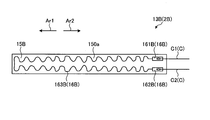
- FIG. 10 and 11 are views showing the seat heater 13B according to the third embodiment.
- FIG. 10 is a view of the seat heater 13B viewed from the first plate surface 150a side.
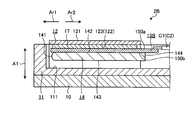
- FIG. 11 is a cross-sectional view corresponding to FIG.
- the treatment tool 2B according to the third embodiment employs a seat heater 13B different from the seat heater 13 described in the first embodiment described above.
- the seat heater 13B is not folded back unlike the seat heater 13 described in the first embodiment described above.
- the sheet heater 13B includes a substrate 15B and a conductive portion 16B (FIG. 10).
- the substrate 15B is a sheet-like substrate made of a resin material having electrical insulation such as polyimide, and its width dimension (length dimension in the vertical direction in FIG. 10) is its longitudinal direction (left and right in FIG. 10). It is set almost uniformly along the direction).
- the conductive portion 16B is vapor-deposited on the first plate surface 150a of the first plate surface 150a (FIGS. 10 and 11) and the second plate surface 150b (FIG. 11) having a front-back relationship with each other in the substrate 15B. It is formed by patterning a metal thin film formed by or sputtering with photolithography. As shown in FIG. 10, the conductive portion 16B includes first and second connecting portions 161B and 162B, and a heat generating portion 163B.
- the first and second connecting portions 161B and 162B extend along the longitudinal direction of the substrate 15B, and at the proximal end side Ar2 of the first plate surface 150a, the substrate 15B They are arranged side by side in the width direction. Then, the first lead wire C1 (FIGS. 10 and 11) constituting the electric cable C is electrically connected to the first connection portion 161B. Further, a second lead wire C2 (FIGS. 10 and 11) constituting the electric cable C is electrically connected to the second connection portion 162B.
- the heat generating portion 163B extends on the first plate surface 150a while meandering from the proximal end side Ar2 toward the distal end side Ar1, and is folded back at the distal end side Ar1 to form a wavy shape toward the proximal end side Ar2. It has a substantially U-shape that extends while meandering. Then, both ends of the heat generating portion 163B are connected to the first and second connecting portions 161B and 162B, respectively.
- the resistance value of the heat generating portion 163B is determined by setting the first and second connecting portions 161B and 162B and the heat generating portion 163B to a predetermined total length and cross-sectional area, respectively, so that the first and second connecting portions 161B, It is set higher than 162B. Therefore, when a voltage is applied to the first and second connection portions 161B and 162B by passing through the first and second lead wires C1 and C2 under the control of the control device 3, heat is generated. Part 163B mainly generates heat.
- FIG. 12 is a flowchart showing a method of manufacturing the treatment tool 2B.
- FIG. 13 is a diagram illustrating a method of manufacturing the treatment tool 2B. In the following, for convenience of explanation, only a method of attaching the seat heater 13B and the block 14 to the blade 12 will be described as a method of manufacturing the treatment tool 2B.
- step S1B adhesive sheet arrangement step
- step S2B jig attaching step.
- the press jig 200B has substantially the same configuration as the jig main body 210 in the press jig 200 described in the first embodiment described above. That is, in step S2B, the operator attaches the press jig 200B to the block 14 by locking the plurality of locking projections 211 of the press jig 200B into the plurality of recesses 145, respectively.
- step S2B the operator arranges the sheet heater 13B on the uncured adhesive sheet 17 in a posture in which the first plate surface 150a faces the adhesive sheet 17.
- step S3B seat heater arranging step.
- the sheet heater 13B is arranged between the uncured adhesive sheet 17 and the block 14.
- step S3B the operator presses (presses) the block 14 toward the bottom surface of the recess 123 with the press jig 200B to bring the uncured adhesive sheet 17 into a compressed state. Further, the operator heats the compressed unit (blade 12, sheet heater 13B, block 14, and press jig 200B) by putting it in a curing furnace (step S4B: hot press step). As a result, the uncured adhesive sheet 17 is cured, and the sheet heater 13B and the block 14 are adhesively fixed to the bottom surface of the recess 123 by the adhesive sheet 17.
- the press device itself may be provided with a heating mechanism so that it can be heated at the same time as the press.
- step S4B the operator removes the press jig 200B from the block 14 as shown in FIG. 13 (d) (step S5B: jig removal step).
- the block 14 is provided with a recess 145. Therefore, by making the air layer in the recess 145 function as a heat insulating layer, the heat transfer from the heat generating portion 163 to the back surface side region Sp2 is restricted, and the heat from the heat generating portion 163 is efficiently transferred to the blade 12. It becomes possible.
- the seat heater 13B is attached to the blade 12 as shown below. That is, after the step S1B, the operator arranges the sheet heater 13B on the uncured adhesive sheet 17. After that, the operator compresses the uncured adhesive sheet 17 by pressing the sheet heater 13B directly toward the bottom surface of the recess 123 with a press jig, and applies heat to the uncured adhesive sheet 17. To cure. Then, when the sheet heater 13B is attached to the blade 12 as described above, the adhesive sheet 17 may stick to the press jig. In this case, there is a problem that the seat heater 13B itself may be destroyed or damaged when the press jig is peeled off.
- step S1B to S5B since the block 14 is provided, the adhesive sheet 17 does not stick to the press jig 200B. That is, the above-mentioned problem does not occur.
- the present invention should not be limited only to the above-described first to third embodiments.
- the block 14 is in contact with the folded portion of the seat heaters 13 and 13A, but the present invention is not limited to this, and a configuration in which the block 14 is not in contact with the folded portion may be adopted. I do not care.
- both thermal energy and high frequency energy are applied to the target portion, but the present invention is not limited to this, and only thermal energy is applied. (A configuration in which the target portion is treated only by the heat from the seat heaters 13 and 13B) may be adopted.
- FIG. 14 is a diagram showing a modified example of the first to third embodiments.
- the recess 145 is used as the heat insulating layer provided on the block 14, but the present invention is not limited to this.
- a through hole 146 penetrating the block 14C may be formed, and the air layer in the through hole 146 may function as a heat insulating layer. That is, the block 14C is composed of a hollow member.
Landscapes
- Health & Medical Sciences (AREA)
- Surgery (AREA)
- Engineering & Computer Science (AREA)
- Life Sciences & Earth Sciences (AREA)
- Biomedical Technology (AREA)
- Otolaryngology (AREA)
- Nuclear Medicine, Radiotherapy & Molecular Imaging (AREA)
- Plasma & Fusion (AREA)
- Physics & Mathematics (AREA)
- Heart & Thoracic Surgery (AREA)
- Medical Informatics (AREA)
- Molecular Biology (AREA)
- Animal Behavior & Ethology (AREA)
- General Health & Medical Sciences (AREA)
- Public Health (AREA)
- Veterinary Medicine (AREA)
- Surgical Instruments (AREA)
Abstract
L'invention concerne un instrument de traitement, comprenant : une lame 12 ayant une surface de traitement 121 qui traite un tissu biologique, et une surface de montage 122 qui a une relation avant/arrière avec la surface de traitement 121 ; un dispositif de chauffage de feuille 13 ayant un substrat qui est formé à partir d'un matériau ayant des propriétés d'isolation électrique, une partie conduction qui a une partie génération de chaleur qui génère de la chaleur par conduction, le substrat ayant une première surface de feuille 150a et une seconde surface de feuille 150b qui ont une relation avant/arrière l'une avec l'autre, et la partie conduction s'étendant le long de la direction longitudinale du substrat sur la première surface de feuille 150a ; et un bloc 14. La première surface de feuille 150a forme la surface externe du dispositif de chauffage de feuille 13, le dispositif de chauffage de feuille 13 est plié le long d'une ligne de pliage orthogonale à la direction longitudinale du substrat, et la partie génération de chaleur est positionnée à l'opposé de la surface de montage 122. Le bloc 14 est positionné à l'intérieur du dispositif de chauffage de feuille 13 qui a été plié le long de la ligne de pliage.
Priority Applications (1)
| Application Number | Priority Date | Filing Date | Title |
|---|---|---|---|
| PCT/JP2019/010382 WO2020183673A1 (fr) | 2019-03-13 | 2019-03-13 | Instrument de traitement et procédé de fabrication d'un instrument de traitement |
Applications Claiming Priority (1)
| Application Number | Priority Date | Filing Date | Title |
|---|---|---|---|
| PCT/JP2019/010382 WO2020183673A1 (fr) | 2019-03-13 | 2019-03-13 | Instrument de traitement et procédé de fabrication d'un instrument de traitement |
Publications (1)
| Publication Number | Publication Date |
|---|---|
| WO2020183673A1 true WO2020183673A1 (fr) | 2020-09-17 |
Family
ID=72426671
Family Applications (1)
| Application Number | Title | Priority Date | Filing Date |
|---|---|---|---|
| PCT/JP2019/010382 Ceased WO2020183673A1 (fr) | 2019-03-13 | 2019-03-13 | Instrument de traitement et procédé de fabrication d'un instrument de traitement |
Country Status (1)
| Country | Link |
|---|---|
| WO (1) | WO2020183673A1 (fr) |
Citations (3)
| Publication number | Priority date | Publication date | Assignee | Title |
|---|---|---|---|---|
| JPH0352419U (fr) * | 1989-09-27 | 1991-05-21 | ||
| WO2018150532A1 (fr) * | 2017-02-17 | 2018-08-23 | オリンパス株式会社 | Outil de traitement |
| WO2018185815A1 (fr) * | 2017-04-03 | 2018-10-11 | オリンパス株式会社 | Outil de traitement thermique |
-
2019
- 2019-03-13 WO PCT/JP2019/010382 patent/WO2020183673A1/fr not_active Ceased
Patent Citations (3)
| Publication number | Priority date | Publication date | Assignee | Title |
|---|---|---|---|---|
| JPH0352419U (fr) * | 1989-09-27 | 1991-05-21 | ||
| WO2018150532A1 (fr) * | 2017-02-17 | 2018-08-23 | オリンパス株式会社 | Outil de traitement |
| WO2018185815A1 (fr) * | 2017-04-03 | 2018-10-11 | オリンパス株式会社 | Outil de traitement thermique |
Similar Documents
| Publication | Publication Date | Title |
|---|---|---|
| EP2939625B1 (fr) | Dispositif de traitement thérapeutique | |
| US20150327909A1 (en) | Treatment apparatus | |
| US20160324566A1 (en) | Treatment apparatus | |
| CN109475380B (zh) | 处置器具 | |
| WO2018185815A1 (fr) | Outil de traitement thermique | |
| JP6487723B2 (ja) | 医療用処置装置 | |
| CN107072703A (zh) | 医疗用处置装置 | |
| US10603097B2 (en) | Treatment energy application structure and medical treatment device | |
| US7458969B2 (en) | Therapeutic device for tissue from living body | |
| WO2020183673A1 (fr) | Instrument de traitement et procédé de fabrication d'un instrument de traitement | |
| US10603096B2 (en) | Treatment-energy applying structure and medical treatment device | |
| WO2018055778A1 (fr) | Instrument de traitement | |
| US20210177487A1 (en) | Medical heater, treatment tool, and treatment tool manufacturing method | |
| WO2020183681A1 (fr) | Dispositif de chauffage médical et instrument de traitement | |
| JP2003325537A (ja) | 医療器械 | |
| WO2020183680A1 (fr) | Instrument de traitement | |
| JP2003325538A (ja) | 医療器械 | |
| WO2019111396A1 (fr) | Procédé de fabrication d'un outil de traitement et outil de traitement | |
| WO2018146729A1 (fr) | Structure d'application d'énergie et outil de traitement | |
| WO2017163410A1 (fr) | Outil de traitement d'énergie | |
| WO2019215908A1 (fr) | Procédé de fabrication de dispositif de chauffage médical, dispositif de chauffage médical, outil de traitement et système de traitement | |
| WO2020044563A1 (fr) | Dispositif de chauffage médical, instrument de traitement et procédé de production d'instrument de traitement | |
| WO2019092845A1 (fr) | Outil de traitement | |
| WO2019215852A1 (fr) | Outil de traitement | |
| WO2018146730A1 (fr) | Structure d'application d'énergie et outil de traitement |
Legal Events
| Date | Code | Title | Description |
|---|---|---|---|
| 121 | Ep: the epo has been informed by wipo that ep was designated in this application |
Ref document number: 19919131 Country of ref document: EP Kind code of ref document: A1 |
|
| NENP | Non-entry into the national phase |
Ref country code: DE |
|
| 122 | Ep: pct application non-entry in european phase |
Ref document number: 19919131 Country of ref document: EP Kind code of ref document: A1 |
|
| NENP | Non-entry into the national phase |
Ref country code: JP |