WO2020183696A1 - 滅菌方法及び滅菌装置 - Google Patents
滅菌方法及び滅菌装置 Download PDFInfo
- Publication number
- WO2020183696A1 WO2020183696A1 PCT/JP2019/010527 JP2019010527W WO2020183696A1 WO 2020183696 A1 WO2020183696 A1 WO 2020183696A1 JP 2019010527 W JP2019010527 W JP 2019010527W WO 2020183696 A1 WO2020183696 A1 WO 2020183696A1
- Authority
- WO
- WIPO (PCT)
- Prior art keywords
- chamber
- ozone
- aqueous solution
- steam
- hydrogen peroxide
- Prior art date
- Legal status (The legal status is an assumption and is not a legal conclusion. Google has not performed a legal analysis and makes no representation as to the accuracy of the status listed.)
- Ceased
Links
Images



Classifications
-
- A—HUMAN NECESSITIES
- A61—MEDICAL OR VETERINARY SCIENCE; HYGIENE
- A61L—METHODS OR APPARATUS FOR STERILISING MATERIALS OR OBJECTS IN GENERAL; DISINFECTION, STERILISATION OR DEODORISATION OF AIR; CHEMICAL ASPECTS OF BANDAGES, DRESSINGS, ABSORBENT PADS OR SURGICAL ARTICLES; MATERIALS FOR BANDAGES, DRESSINGS, ABSORBENT PADS OR SURGICAL ARTICLES
- A61L2/00—Disinfection or sterilisation of materials or objects, in general; Accessories therefor
- A61L2/16—Disinfection or sterilisation of materials or objects, in general; Accessories therefor using chemical substances
- A61L2/20—Gaseous substances, e.g. vapours
- A61L2/208—Hydrogen peroxide
-
- A—HUMAN NECESSITIES
- A61—MEDICAL OR VETERINARY SCIENCE; HYGIENE
- A61L—METHODS OR APPARATUS FOR STERILISING MATERIALS OR OBJECTS IN GENERAL; DISINFECTION, STERILISATION OR DEODORISATION OF AIR; CHEMICAL ASPECTS OF BANDAGES, DRESSINGS, ABSORBENT PADS OR SURGICAL ARTICLES; MATERIALS FOR BANDAGES, DRESSINGS, ABSORBENT PADS OR SURGICAL ARTICLES
- A61L2/00—Disinfection or sterilisation of materials or objects, in general; Accessories therefor
- A61L2/16—Disinfection or sterilisation of materials or objects, in general; Accessories therefor using chemical substances
- A61L2/18—Liquid substances
- A61L2/186—Peroxide solutions
-
- A—HUMAN NECESSITIES
- A61—MEDICAL OR VETERINARY SCIENCE; HYGIENE
- A61L—METHODS OR APPARATUS FOR STERILISING MATERIALS OR OBJECTS IN GENERAL; DISINFECTION, STERILISATION OR DEODORISATION OF AIR; CHEMICAL ASPECTS OF BANDAGES, DRESSINGS, ABSORBENT PADS OR SURGICAL ARTICLES; MATERIALS FOR BANDAGES, DRESSINGS, ABSORBENT PADS OR SURGICAL ARTICLES
- A61L2/00—Disinfection or sterilisation of materials or objects, in general; Accessories therefor
- A61L2/16—Disinfection or sterilisation of materials or objects, in general; Accessories therefor using chemical substances
- A61L2/20—Gaseous substances, e.g. vapours
- A61L2/202—Ozone
-
- A—HUMAN NECESSITIES
- A61—MEDICAL OR VETERINARY SCIENCE; HYGIENE
- A61L—METHODS OR APPARATUS FOR STERILISING MATERIALS OR OBJECTS IN GENERAL; DISINFECTION, STERILISATION OR DEODORISATION OF AIR; CHEMICAL ASPECTS OF BANDAGES, DRESSINGS, ABSORBENT PADS OR SURGICAL ARTICLES; MATERIALS FOR BANDAGES, DRESSINGS, ABSORBENT PADS OR SURGICAL ARTICLES
- A61L2/00—Disinfection or sterilisation of materials or objects, in general; Accessories therefor
- A61L2/26—Accessories
-
- A—HUMAN NECESSITIES
- A61—MEDICAL OR VETERINARY SCIENCE; HYGIENE
- A61L—METHODS OR APPARATUS FOR STERILISING MATERIALS OR OBJECTS IN GENERAL; DISINFECTION, STERILISATION OR DEODORISATION OF AIR; CHEMICAL ASPECTS OF BANDAGES, DRESSINGS, ABSORBENT PADS OR SURGICAL ARTICLES; MATERIALS FOR BANDAGES, DRESSINGS, ABSORBENT PADS OR SURGICAL ARTICLES
- A61L2103/00—Materials or objects being the target of disinfection or sterilisation
- A61L2103/15—Laboratory, medical or dentistry appliances, e.g. catheters or sharps
-
- A—HUMAN NECESSITIES
- A61—MEDICAL OR VETERINARY SCIENCE; HYGIENE
- A61L—METHODS OR APPARATUS FOR STERILISING MATERIALS OR OBJECTS IN GENERAL; DISINFECTION, STERILISATION OR DEODORISATION OF AIR; CHEMICAL ASPECTS OF BANDAGES, DRESSINGS, ABSORBENT PADS OR SURGICAL ARTICLES; MATERIALS FOR BANDAGES, DRESSINGS, ABSORBENT PADS OR SURGICAL ARTICLES
- A61L2202/00—Aspects relating to methods or apparatus for disinfecting or sterilising materials or objects
- A61L2202/10—Apparatus features
- A61L2202/12—Apparatus for isolating biocidal substances from the environment
- A61L2202/122—Chambers for sterilisation
Definitions
- This disclosure relates to a sterilization method and a sterilizer.
- Patent Document 1 describes a sterilization method including a series of steps of injecting steam of an aqueous hydrogen peroxide solution to sterilize and hold the chamber containing the object to be sterilized, and then injecting ozone gas to sterilize and hold the chamber. The device is disclosed.
- the sterilization method is a method of sterilizing an object to be sterilized contained in a chamber, and injects steam generated from a first aqueous solution of hydrogen peroxide into the chamber. 1 After the steam injection step, the first steam injection step, the ozone injection step of injecting ozone gas into the chamber, and after the ozone injection step, the steam or hydrogen peroxide generated from pure water is inside the chamber. It includes a second steam injection step of injecting steam generated from the second aqueous solution.
- the sterilizer according to the second aspect of the present disclosure communicates with a chamber for accommodating an object to be sterilized and a first aqueous solution of hydrogen peroxide, or a second aqueous solution of hydrogen peroxide or pure water. Controls the operation of injecting the vapor generated by the evaporator or the steam generated by the evaporator or the ozone gas generated by the ozone generator into the chamber of the evaporator that generates ozone gas by communicating with the evaporator that evaporates and fills the chamber.
- the control unit is provided with a control unit for injecting ozone gas after injecting steam generated from the first aqueous solution into the chamber, and after injecting the ozone gas, the control unit injects steam generated from pure water or a second.
- the vapor generated from the aqueous solution is injected to sterilize the object to be sterilized.
- FIG. 1 is a schematic view showing the configuration of the sterilizer according to the first embodiment.
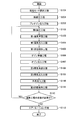
- FIG. 2 is a flowchart showing the flow of the sterilization method according to the first embodiment.
- FIG. 3 is a table showing each processing mode implemented by the sterilizer according to the first embodiment.
- FIG. 4 is a table showing various conditions in the sterilization treatment test according to the first embodiment.
- FIG. 5 is a table showing the results when the sterilization treatment test is performed under the conditions shown in FIG.
- FIG. 6 is a graph showing the pressure change inside the chamber in the case of Comparative Example 1.
- FIG. 7 is a graph showing the pressure change inside the chamber in the case of Comparative Example 2.
- FIG. 8 is a graph showing the pressure change inside the chamber in the case of the embodiment.
- FIG. 9 is a flowchart showing the flow of the sterilization method according to the second embodiment.
- FIG. 10 is a graph showing the pressure change inside the chamber in the second embodiment.
- FIG. 1 is a schematic view showing the configuration of the sterilizer 100 according to the first embodiment.
- the sterilizer 100 sterilizes the object to be sterilized with a sterilizing gas.
- the substances constituting the sterilizing gas used in this embodiment are mainly hydrogen peroxide (H 2 O 2 ) and ozone (O 3 ).
- the sterilized object is assumed to be a medical device used for surgery or treatment in a hospital and in contact with the vascular system or sterile tissue.
- medical devices include heat-resistant steel products such as forceps, knives, and shear blades, stainless steel hard endoscopes for laparoscopic surgery, and soft endoscopes for bronchial and urinary surgery.
- non-heat resistant resin products such as power cables, which are accessories thereof.
- the object to be sterilized shall be housed in the chamber 11 of the sterilizer 100 in a state of being previously put in a sterilization bag or wrapped in a sterilization wrap in advance.
- Sterilization bags and sterilization wraps are non-woven fabrics mainly made of resins such as polyethylene, and because the mesh is fine, sterilization gas can pass through, but bacteria cannot.
- the sterilizer 100 includes a chamber unit 10, a hydrogen peroxide supply unit 20, an ozone supply unit 30, an exhaust unit 40, an atmosphere introduction unit 50, and a control unit 60.
- the chamber unit 10 includes a chamber 11 for accommodating an object to be sterilized and its peripheral configuration.
- the chamber unit 10 includes a chamber 11 including a door 12, a first heater 13, and a first pressure gauge 14.
- Chamber 11 is a container in which a sterilized object can be placed and stored.
- the chamber 11 is also called a sterilizer.
- the chamber 11 is made of stainless steel or an aluminum alloy and has a structure that can withstand vacuum and decompression.
- the internal volume of the chamber 11 is 100 L.
- the door 12 can be opened and closed with respect to the chamber 11. When the door 12 is closed and the inside of the chamber 11 is depressurized, the chamber 11 is sealed to suppress a vacuum leak and a leak of sterilizing gas.
- the first heater 13 is installed around the chamber 11 together with a heat insulating material to keep the temperature inside the chamber 11 constant during the sterilization process.
- the temperature of the chamber 11 is measured by a thermometer (not shown) installed in the chamber 11.
- the first pressure gauge 14 is a vacuum gauge installed in the chamber 11 and measures the pressure inside the chamber 11.
- the hydrogen peroxide supply unit 20 supplies hydrogen peroxide vapor to the chamber 11 during the sterilization process.
- the hydrogen peroxide supply unit 20 can individually supply the vapors generated from the two aqueous solutions of hydrogen peroxide.
- first aqueous solution one aqueous solution of hydrogen peroxide
- second aqueous solution one aqueous solution of hydrogen peroxide
- the concentration of hydrogen peroxide contained in the first aqueous solution and the concentration of hydrogen peroxide contained in the second aqueous solution will be described in detail below, but are based on the presence or absence of a lumen of the sterilized object and the material of the sterilized object. Is regulated.
- the hydrogen peroxide supply unit 20 includes a bottle 21, an extraction pipe 22, a tube pump 23, a storage unit 24, an evaporator 26, and a second heater 29.
- the bottle 21 contains an aqueous solution of hydrogen peroxide.
- the bottle 21 is also called a cartridge if it is used as a so-called disposable bottle.
- the extraction pipe 22 extracts an aqueous solution of hydrogen peroxide from the bottle 21 and supplies the extracted aqueous solution to the storage unit 24.
- the tube pump 23 is installed in the middle of the extraction pipe 22, and sucks out an appropriate amount of an aqueous solution of hydrogen peroxide from the bottle 21.
- the extraction pipe 22 may be provided with, for example, an optical liquid level sensor.
- the tube pump 23 pumps an aqueous solution of hydrogen peroxide until the liquid level sensor reacts, and when the liquid level sensor reacts, it stops once and then rotates by a predetermined rotation speed to supply a specified amount to the storage unit 24. ..
- the storage unit 24 is connected to the extraction pipe 22 and temporarily stores the specified amount of hydrogen peroxide aqueous solution sucked up from the bottle 21 before sending it to the evaporator 26.
- a translucent fluororesin tube or the like in which the amount of liquid inside can be seen can be adopted. Since the tube pump 23 can stably supply a fixed amount when driven under atmospheric pressure, the storage unit 24 may introduce the atmosphere through the first filter 25 so as to reach atmospheric pressure.
- the first filter 25 is, for example, a HEPA filter.
- the evaporator 26 communicates with the storage unit 24 via the first supply pipe 27 to evaporate the aqueous solution of hydrogen peroxide introduced from the storage unit 24.
- the evaporator 26 is made of, for example, stainless steel so as to withstand the corrosion of hydrogen peroxide, and is decompressed at the same time as the chamber 11, so that the evaporator 26 has a structure capable of withstanding vacuum and decompression.
- a first solenoid valve 70 is installed in the first supply pipe 27.
- the first solenoid valve 70 is opened, the aqueous solution of hydrogen peroxide in the storage unit 24 is sucked toward the decompressed evaporator 26.
- the storage unit 24 introduces the atmosphere through the first filter 25 and is under atmospheric pressure, the atmosphere is also sucked together with the aqueous solution of hydrogen peroxide.
- the aqueous solution of hydrogen peroxide remaining in the storage unit 24 and the first supply pipe 27 is also sucked into the evaporator 26, so that the vapor of hydrogen peroxide is quantitatively and stably sent into the chamber 11. ..
- the evaporator 26 communicates with the chamber 11 via a plurality of injection pipes 28.
- a second solenoid valve 71 is installed in the first injection pipe 28a
- a third solenoid valve 72 is installed in the second injection pipe 28b.
- the evaporator 26 is provided with a pressure sensor 39 for determining whether or not a predetermined amount of steam has been supplied from the storage unit 24 based on whether or not the vapor is within a predetermined pressure range after the injection of steam. May be good.
- the second heater 29 is installed around the evaporator 26 and keeps the temperature inside the evaporator 26 constant.
- the inside of the evaporator 26 is kept constant at a predetermined temperature, for example, between 65 and 120 ° C.
- the ozone supply unit 30 supplies ozone gas to the chamber 11 during the sterilization process.
- ozone gas is generated in the ozone supply unit 30.
- the ozone supply unit 30 includes an oxygen generator 31, an ozone generator 32, an ozone concentration meter 33, a buffer tank 34, and a second pressure gauge 35.
- the oxygen generator 31 generates oxygen (O 2 ), which is a raw material for ozone.
- oxygen O 2
- a PSA Pressure Swing Adsorption
- the oxygen generator 31 may be a PSA device having a discharge pressure of about 0.03 to 0.08 MPa as a gauge pressure and a flow rate of about 1 to 4 L / min.
- a fourth solenoid valve 73 is installed in a pipe that connects the oxygen generator 31 and the ozone generator 32. By appropriately controlling the opening and closing of the fourth solenoid valve 73, the amount of oxygen supplied to the ozone generator 32 is adjusted.
- the ozone generator 32 generates ozone gas from the oxygen generated by the oxygen generator 31.
- a silent discharge method of generating ozone by applying a high frequency high voltage to oxygen to discharge and decompose it can be adopted.
- the ozone supply unit 30 as an example, there are two ozone generators 32.
- the ozone generator 32 communicates with the buffer tank 34 via the second supply pipe 36.
- a fifth solenoid valve 74 is installed between the ozone concentration meter 33 and the buffer tank 34 in the second supply pipe 36. Further, the ozone concentration meter 33 and the fifth solenoid valve 74 in the second supply pipe 36 may communicate with the exhaust unit 40 via the pipe system X including the sixth solenoid valve 75. That is, when the fifth solenoid valve 74 is closed and the sixth solenoid valve 75 is open, the ozone gas circulated from the ozone generator 32 is supplied to the exhaust unit 40 side.
- the buffer tank 34 temporarily stores the ozone gas generated by the ozone generator 32 before sending it to the evaporator 26.
- the buffer tank 34 is made of, for example, stainless steel so as to withstand the corrosion of hydrogen peroxide, and has a structure capable of withstanding reduced pressure.
- the volume of the buffer tank 34 is assumed to be 2 L.
- the buffer tank 34 communicates with the evaporator 26 via the third supply pipe 37.
- a seventh solenoid valve 76 is installed in the third supply pipe 37. If ozone gas is injected into the buffer tank 34 when the seventh solenoid valve 76 is closed, the pressure inside the buffer tank 34 temporarily increases.
- the second pressure gauge 35 is a vacuum gauge installed in the buffer tank 34 and measures the pressure inside the buffer tank 34.
- the control unit 61 monitors the pressure inside the buffer tank 34 using the second pressure gauge 35, so that ozone is injected into the buffer tank 34 to a predetermined pressure, or the second supply pipe 36 or the like. It is possible to check whether or not ozone leakage or clogging has occurred.
- the ozone gas supplied from the buffer tank 34 is not directly injected into the chamber 11, but is injected via the evaporator 26. That is, the port for introducing the sterilizing gas into the chamber 11 is common to hydrogen peroxide and ozone gas.
- ozone gas may be directly charged into the chamber 11 from the buffer tank 34 without passing through the evaporator 26.
- the ozone gas since the ozone gas is injected into the chamber 11 without passing through the evaporator 26, there is an advantage that the diffusion of the ozone gas in the chamber 11 is accelerated.
- the second solenoid valve 71 and the third solenoid valve 72 between the evaporator 26 and the chamber 11 are closed, there is an advantage that the ozone concentration in the chamber 11 is increased.
- the exhaust unit 40 decompresses the inside of the chamber 11 and discharges the gas existing inside the chamber 11 to the outside. Specifically, in order to improve the sterilization effect during the sterilization process, the exhaust unit 40 removes excess gas from the chamber 11 and the sterilization object itself before the sterilization process, for example, at a medium vacuum level of 100 Pa or less. The inside of the chamber 11 is depressurized until. Further, the exhaust unit 40 removes the sterilizing gas remaining in the chamber 11 and the object to be sterilized after the sterilization treatment.
- the exhaust unit 40 includes a vacuum pump 41, a catalyst tank, and a heater.
- the vacuum pump 41 for example, a dry pump such as a scroll pump compatible with medium vacuum or an oil rotary pump such as a rotary pump can be adopted.
- the vacuum pump 41 is an oil rotary pump.
- the vacuum pump 41 and the chamber 11 communicate with each other via an exhaust pipe 38.
- An eighth solenoid valve 77 is installed in the exhaust pipe 38. For example, at the time of depressurization, when the pressure inside the chamber 11 reaches a predetermined value, the control unit 61 closes the eighth solenoid valve 77 and stops the operation of the vacuum pump 41.
- the catalyst tank is made of stainless steel, for example, and contains a catalyst such as a pellet type or a honeycomb type.
- the catalyst decomposes hydrogen peroxide and ozone, for example, with manganese dioxide as a main component.
- the first catalyst tank 42 is a catalyst tank installed on the upstream side of the vacuum pump 41.
- the second catalyst tank 43 is a catalyst tank installed on the downstream side of the vacuum pump 41.
- the ozone supply unit 30 supplies ozone gas to the exhaust unit 40 via the piping system X by appropriately controlling the ozone generator 32, the fifth solenoid valve 74, and the sixth solenoid valve 75. It is possible.
- the heater keeps the catalyst tank warm at, for example, 60 to 90 ° C.
- the third heater 44 keeps the first catalyst tank 42 warm.
- the fourth heater 45 keeps the second catalyst tank 43 warm.
- the atmosphere introduction unit 50 introduces the atmosphere into the chamber 11.
- the atmosphere introduction unit 50 includes a second filter 51 and a plurality of introduction ports.
- the second filter 51 prevents dust in the atmosphere from entering the inside of the chamber 11 when the atmosphere is introduced.
- a HEPA filter which is a fine-grained non-woven fabric filter can be adopted.
- the introduction port introduces the air introduced through the second filter 51 into the chamber 11. It is desirable that a plurality of introduction ports are installed at different positions in the chamber 11 in order to equalize the gas concentration inside the chamber 11 in accordance with the introduction of the atmosphere.
- a plurality of introduction ports are installed at different positions in the chamber 11 in order to equalize the gas concentration inside the chamber 11 in accordance with the introduction of the atmosphere.
- a ninth solenoid valve 78 is installed in the first introduction port 52.
- a tenth solenoid valve 79 is installed in the second introduction port 53.
- the introduction port is not limited to the one provided directly to the chamber 11.
- the introduction port may be continuous to the chamber 11 via, for example, the evaporator 26.
- the introduction port may be continuous to the chamber 11 via, for example, the buffer tank 34.
- the introduction port may be continuous to the chamber 11 via, for example, both the evaporator 26 and the buffer tank 34.
- the control unit 60 controls the driving of the power system elements in each unit constituting the sterilizer 100 based on various operation commands.
- the control unit 60 includes a control unit 61 and a touch panel 62.
- the control unit 61 is electrically connected to various power system elements, measurement system elements, and the like.
- the control unit 61 controls the operation of various power system elements based on, for example, a command input via the touch panel 62, a control sequence held in advance, a detection signal from each sensor, or the like.
- the touch panel 62 is electrically connected to the control unit 61 and is used for the operator to input information and commands and to visually recognize the information presented from the device side.
- FIG. 2 is a flowchart showing the flow of the sterilization method according to the present embodiment.
- the sterilization process by the sterilization method according to the present embodiment is roughly classified into, for example, three steps.
- the first first step is a pretreatment step including the process mode selection step S101.
- the second step is a sterilization step including each step from the first decompression step S102 to the second state holding step S111.
- the final third step is the aeration step S113.
- an operator such as a hospital nurse places an object to be sterilized in the chamber 11 and closes the door 12 to seal the inside of the chamber 11. At this point, it is assumed that the power of the sterilizer 100 has already been turned on and the warm-up operation and the like have been completed.
- the operator can select the process mode according to the type of the object to be sterilized.
- the types of sterilization objects are classified according to, for example, the shape and material of the sterilization object.
- the shape of the object to be sterilized may be classified according to the presence or absence of a lumen.
- the processing mode selection step S101 is a step of inputting the processing mode selected by the operator into the sterilizer 100.
- FIG. 3 is a table showing each processing mode that can be performed by the sterilizer 100.
- the processing mode for example, the following three modes may be set.
- the short mode is applied when the object to be sterilized is a medical device that does not have a lumen.
- the medical equipment in this case is mainly surface-sterilized, for example, a steel product such as forceps.
- the standard mode is applied when the object to be sterilized is a resin medical device with a lumen.
- the long mode is applied when the object to be sterilized is a stainless steel medical device with a lumen.
- the medical device in this case is, for example, a rigid endoscope having a thin tube having an inner diameter of about 1 mm.
- the injection amount of the aqueous solution of hydrogen peroxide, or the number of exposures is different.
- the column of the injection amount of the aqueous solution of hydrogen peroxide in the table in FIG. 3 the range in which the numerical value per pulse corresponding to one series of sterilization steps can be taken is described.
- the upper row shows the algebra related to the injection amount of the first aqueous solution
- the lower row shows the algebra related to the injection amount of the second aqueous solution.
- the sterilization step according to the present embodiment first includes a first decompression step S102, a first steam preparation step S103, a first steam injection step S104, and a first state holding step S105.
- the first decompression step S102 is a step of exhausting excess gas contained in the sterilized object by decompressing the inside of the chamber 11 to a certain degree of vacuum.
- the control unit 61 opens the eighth solenoid valve 77 to reduce the pressure inside the chamber 11.
- the control unit 61 opens the second solenoid valve 71, the third solenoid valve 72, and the seventh solenoid valve 76, respectively, to reduce the pressure inside each of the evaporator 26 and the buffer tank 34 together with the chamber 11.
- the processing time in the table in FIG. 3 is calculated from the time when the depressurization starts at this time.
- the target pressure in the first depressurizing step S102 is 50 Pa or less.
- the control unit 61 closes the second solenoid valve 71, the third solenoid valve 72, the seventh solenoid valve 76, and the eighth solenoid valve 77, and stops the vacuum pump 41.
- the control unit 61 shifts to the first steam preparation step S103 after the first decompression step S102.
- the object to be sterilized is, for example, a thin tube made of stainless steel. Therefore, when the long mode is selected, the temperature of the object to be sterilized is raised in advance, and the pressure is maintained for a certain period of time, for example, about 2 minutes, so that the influence of dew condensation in the lumen is minimized. You may.
- the first steam preparation step S103 is a step of generating the steam of the first aqueous solution to be injected in the next first steam injection step S104.
- the control unit 61 rotates the first tube pump 23a to suck up the first aqueous solution from the first bottle 21a, and then injects a predetermined amount of the first aqueous solution into the storage unit 24 in equal portions.
- the specified amount is the total input amount per pulse, and differs depending on the processing mode as shown in FIG. For example, when the treatment mode is the short mode, the concentration of hydrogen peroxide contained in the first aqueous solution is a predetermined concentration (x1) between 30 and 60%, and the specified amount is between 1 and 4 ml. It is a predetermined amount (y1).
- the control unit 61 opens the first solenoid valve 70 for a certain period of time, for example, 5 seconds. Since the inside of the evaporator 26 has already been depressurized, the first aqueous solution is instantly sucked into the evaporator 26. At this time, since the storage unit 24 communicates with the atmosphere through the first filter 25, when the air enters the storage unit 24, the first aqueous solution remaining in the storage unit 24, the first supply pipe 27, and the like is also an evaporator. It will be sent to 26.
- the control unit 61 closes the first solenoid valve 70 and evaporates the first aqueous solution with the evaporator 26 for a certain period of time, for example, 5 seconds.
- the evaporator 26 is constantly heated at a predetermined temperature, for example, between 65 and 120 ° C.
- a predetermined temperature for example, between 65 and 120 ° C.
- the control unit 61 shifts to the first steam injection step S104 after the first steam preparation step S103.
- the first steam injection step S104 is a step of injecting the steam of the first aqueous solution generated by the evaporator 26 into the inside of the chamber 11.
- the control unit 61 opens the second solenoid valve 71 and the third solenoid valve 72 for a certain period of time, for example, 10 seconds.
- the steam of the first aqueous solution is vigorously injected into the chamber 11 according to the pressure difference.
- the larger the pressure difference the easier it is for vapor to permeate into the inside of the lumen.
- the steam is easily homogenized inside the chamber 11.
- the control unit 61 closes the second solenoid valve 71 and the third solenoid valve 72. After that, the control unit 61 repeats the injection of the steam of the first aqueous solution in the same procedure according to the processing mode.
- the processing mode is the short mode
- the vapor of the first aqueous solution of a predetermined concentration (x1) x 1 to 4 ml between 30 to 60% per pulse and a predetermined amount (y1) is evaporated 26. Will be injected into.
- the saturated vapor pressure is reached inside the evaporator 26, and the first aqueous solution may not be sufficiently evaporated and may remain.
- control unit 61 may evaporate the first aqueous solution in two portions, for example, half each, and inject it into the chamber 11 each time.
- control unit 61 may inject the steam of the first aqueous solution into a plurality of times.
- the control unit 61 shifts to the first state holding step S105 after the first steam injection step S104.
- the first state holding step S105 is a step of sterilizing the object to be sterilized by holding the vapor of the first aqueous solution in the chamber 11 for a certain period of time.
- the holding time at this time differs depending on the processing mode.
- the holding time in the short mode is, for example, 3 minutes.
- the holding time in the standard mode is, for example, 4 minutes.
- the holding time in the long mode is, for example, 6 minutes. That is, the holding time gradually increases in the order of short mode, standard mode, and long mode.
- the sterilization step includes an ozone preparation step S106 and an ozone injection step S107.
- the ozone preparation step S106 is a step of generating ozone gas to be injected in the next ozone injection step S107.
- the ozone preparation step S106 is not necessarily executed after waiting for the completion of the first state holding step S105, but may be executed before the ozone injection step S107 is started, and ozone gas may be prepared.
- the control unit 61 opens the fourth solenoid valve 73 to supply oxygen having a concentration of, for example, 95% to the ozone generator 32.
- the control unit 61 closes the fifth solenoid valve 74 and opens the sixth solenoid valve 75 for about several tens of seconds after driving the ozone generator 32, so that the oxygen and ozone concentrations are increased.
- Ozone gas may not be sent to the buffer tank 34 but flow to the piping system of the first catalyst tank 42 until it becomes stable.
- the control unit 61 closes the sixth solenoid valve 75 and opens the fifth solenoid valve 74, so that the buffer tank 34 is filled with ozone gas for a constant flow rate, a constant concentration, and a constant time.
- the control unit 61 closes the fifth solenoid valve 74 and stops the drive of the ozone generator 32 after the filling of the buffer tank 34 with ozone gas is completed.
- the ozone injection step S107 is a step of injecting the ozone gas generated in the ozone preparation step S106 into the chamber 11.
- the ozone injection step S107 is executed after the first state holding step S105 is completed.
- the control unit 61 opens the seventh solenoid valve 76, the second solenoid valve 71, and the third solenoid valve 72 for a certain period of time, for example, for 5 seconds, and injects ozone gas into the chamber 11.
- the pressure inside the buffer tank 34 is, for example, a predetermined pressure having a maximum gauge pressure of about 0.03 to 0.08 MPa, or a predetermined pressure having an absolute pressure of about 0.13 to 0.18 MPa. Pressure.
- the sterilizer 100 can efficiently inject a small amount of ozone into the chamber 11 and contribute to sterilization.
- the sterilization step includes a second steam preparation step S108, a second steam injection step S109, an outside air injection step S110, and a second state holding step S111.
- the second steam preparation step S108 is a step of generating the steam of the second aqueous solution to be injected in the next second steam injection step S109.
- the second steam preparation step S108 is not necessarily executed after waiting for the completion of the ozone injection step S107, but is executed before the second steam injection step S109 is started, and the steam of the second aqueous solution is prepared. Just do it.
- the generation of the steam of the second aqueous solution may be performed in the same procedure as the generation of the steam of the first aqueous solution in the first steam preparation step S103.
- the control unit 61 rotates the second tube pump 23b to suck up the second aqueous solution from the second bottle 21b, and then injects a specified amount into the storage unit 24 in equal divisions.
- the concentration of hydrogen peroxide contained in the second aqueous solution is a predetermined concentration (x2) between 0.1 and 10%
- the specified amount is 2 to 8 ml. It is a predetermined amount (y2) between.
- the equally divided amount of the specified amount is a predetermined amount (y2 / 2) between 1 and 4 ml, which is half of y2.
- the control unit 61 opens the first solenoid valve 70 for a certain period of time, for example, 5 seconds. Since the inside of the evaporator 26 has already been depressurized, the second aqueous solution is instantly sucked into the evaporator 26. At this time, since the storage unit 24 communicates with the atmosphere through the first filter 25, when the air enters the storage unit 24, the second aqueous solution remaining in the storage unit 24, the first supply pipe 27, and the like is also an evaporator. It will be sent to 26. Next, the control unit 61 closes the first solenoid valve 70 and evaporates the second aqueous solution with the evaporator 26 for a certain period of time, for example, 5 seconds.
- the evaporator 26 is constantly heated at a predetermined temperature, for example, between 65 and 120 ° C.
- a predetermined temperature for example, between 65 and 120 ° C.
- the amount of the second aqueous solution is adjusted so that it evaporates almost completely inside the evaporator 26 having a volume of 0.5 to 2 L and a pressure of 50 Pa, the saturated vapor pressure is applied. It is thought that the pressure will increase to a certain extent.
- the control unit 61 shifts to the second steam injection step S109 after the second steam preparation step S108.
- the second steam injection step S109 is a step of injecting the steam of the second aqueous solution generated by the evaporator 26 into the chamber 11.
- Ozone gas alone is difficult to contribute to sterilization, but the addition of water increases its reactivity. It is considered that this is because OH radicals and the like are generated when ozone reacts with water or residual hydrogen peroxide on the surface of the bacterium, effectively destroying the cell wall of the bacterium. Therefore, in the present embodiment, the vapor of the second aqueous solution is injected into the inside of the chamber 11 immediately after the injection of ozone gas is completed. It is presumed that the hydrogen peroxide in the vapor injected into the chamber 11 invades the bacterial cells through the cell wall destroyed by ozone and attacks the cell nucleus, thereby improving the sterilization effect. To.
- the concentration of hydrogen peroxide contained in the second aqueous solution is 30 to 60%, which is equivalent to the concentration of hydrogen peroxide contained in the first aqueous solution. It is set to a predetermined value (x1) between.
- the input amount per pulse is a predetermined value (y2) between 2 and 8 ml in the short mode and the standard mode, whereas it is a predetermined amount between 1 and 5 ml in the long mode. It can be set as low as (y3).
- the second steam injection step S109 is executed immediately after the ozone injection step S107 is completed.
- the injection of the steam of the second aqueous solution may be performed in the same procedure as the injection of the steam of the first aqueous solution in the first steam injection step S104.
- the control unit 61 opens the second solenoid valve 71 and the third solenoid valve 72 for a certain period of time, for example, 10 seconds, and injects the steam of the second aqueous solution into the chamber 11.
- the control unit 61 closes the second solenoid valve 71 and the third solenoid valve 72.
- the control unit 61 repeats the injection of the steam of the second aqueous solution in the same procedure according to the processing mode.
- the control unit 61 evaporates the second aqueous solution in two portions, for example, half of y2 (2 to 8 ml), and injects the second aqueous solution into the chamber 11 each time. You may.
- the control unit 61 may inject the steam of the second aqueous solution in a plurality of times.
- the control unit 61 shifts to the outside air injection step S110 after the second steam injection step S109.
- the steam of the second aqueous solution of hydrogen peroxide is injected, but instead of the second aqueous solution, purified water or the like that has been sterilized or sterilized.
- the steam of pure water may be injected.
- pure water is contained in the second bottle 21b.
- pure water is evaporated.
- the concentration of hydrogen peroxide (a predetermined value between x2, 0.1% and 10%) contained in the second aqueous solution is the second. It is significantly lower than the concentration of hydrogen peroxide contained in one aqueous solution (a predetermined value between x1, 30 and 60%). Therefore, for example, when either of these two treatment modes can be selected and the sterilization effect is not required more than necessary for the sterilized object, pure water is used instead of the second aqueous solution. You may. As a result, the amount of hydrogen peroxide used can be reduced as a whole in the sterilization process.
- the outside air injection step S110 is a step of injecting outside air, which is air or dry nitrogen gas, into the inside of the chamber 11.
- outside air is the atmosphere.
- the outside air injection step S110 is executed immediately after the second steam injection step S109 is completed.
- By injecting air into the chamber 11, for example, hydrogen peroxide and ozone gas that have stagnated in the middle of the lumen of a sterilized object having a lumen are pushed in, and sterilization is further promoted. .. Further, by injecting air into the chamber 11, the concentration distribution of the gas existing in the chamber 11 becomes uniform, and sterilization is performed evenly.
- the control unit 61 injects the atmosphere into the chamber 11 via the atmosphere introduction unit 50. Specifically, the control unit 61 adjusts the injection amount of the atmosphere introduced through the second filter 51 by appropriately controlling the opening and closing of the ninth solenoid valve 78 and the tenth solenoid valve 79. At this time, the atmosphere is injected until a certain pressure is reached. In the present embodiment, the control unit 61 closes the ninth solenoid valve 78 and the tenth solenoid valve 79 when the atmosphere is injected until the pressure inside the chamber 11 reaches about 90 kPa, which is about 90% of the atmospheric pressure. .. This is because if the internal pressure and the external pressure of the chamber 11 become the same, gas may leak to the outside from the seal portion of the door 12. The control unit 61 shifts to the second state holding step S111 after the outside air injection step S110.
- the outside air injection step S110 is particularly effective when selecting the standard mode or the long mode applied when the sterilized object has a lumen.
- the short mode in which the sterilized object does not have a lumen and the surface sterilization of the sterilized object is mainly performed, if the desired sterilization effect can be obtained, the process content can be simplified. From the viewpoint, the outside air injection step S110 may not be executed.
- the second state holding step S111 is a step of holding the internal state of the chamber 11 for a certain period of time after the outside air injection step S110 is completed. By maintaining the internal state of the chamber 11 for a certain period of time in this way, the sterilization action as described in the outside air injection step S110 is further promoted.
- the holding time here differs depending on the processing mode.
- the holding time in the short mode is, for example, 2 minutes.
- the holding time in the standard mode is, for example, 3 minutes.
- the holding time in the long mode is, for example, 5 minutes.
- the sterilization process up to this point may be repeated as many times as necessary depending on the object to be sterilized. Therefore, the control unit 61 determines whether or not it is necessary to repeat the series of sterilization steps after the second state holding step S111 is completed (S112). One sterilization step is counted as one exposure, and the number of exposures is hereinafter expressed as the number of pulses.
- the control unit 61 determines that a further sterilization step is required (YES)
- the control unit 61 shifts to the first decompression step S102 and executes the second pulse sterilization step.
- the control unit 61 determines that a further sterilization step is not required (NO)
- the control unit 61 shifts to the next aeration step S113.
- the required number of pulses is specified so that a sterilization guarantee level (SAL ⁇ 10-6 ) of 10-6 or less is achieved.
- SAL ⁇ 10-6 sterilization guarantee level
- it is a condition that 10 to 6 or more indicator bacteria are completely killed in a half-cycle sterilization step corresponding to one pulse.
- two pulses are set as a full cycle in all three processing modes.
- the aeration step S113 is a step of removing hydrogen peroxide and ozone as sterilizing gas by reducing the pressure inside the chamber 11 to a certain degree of vacuum, and then injecting air to near atmospheric pressure to dilute the sterilizing gas. Is.
- the processing in the aeration step S113 differs depending on whether the processing mode is the short mode or the other mode.
- the processing in the aeration step S113 when the processing mode is the short mode will be described.
- the short mode the contact time between the sterilizing gas and the sterilized object is shorter than in other modes. Therefore, the aeration step S113 in this case includes, for example, the following processing steps in order to shorten the processing time.
- the control unit 61 starts the vacuum pump 41 as quickly as possible, opens the eighth solenoid valve 77, and starts depressurizing the inside of the chamber 11.
- the control unit 61 opens the second solenoid valve 71, the third solenoid valve 72, and the seventh solenoid valve 76 to discharge the residual gas inside the evaporator 26 and the buffer tank 34.
- depressurization is continued until the pressure inside the chamber 11 reaches, for example, 100 Pa.
- the discharged sterilized gas passes through the first catalyst tank 42 and the second catalyst tank 43, so that hydrogen peroxide is decomposed into harmless water and oxygen, while ozone is decomposed into harmless oxygen.
- the control unit 61 closes the eighth solenoid valve 77 when the pressure inside the chamber 11 reaches a predetermined depressurizing pressure.
- the control unit 61 opens the ninth solenoid valve 78 and the tenth solenoid valve 79, and injects the atmosphere into the chamber 11 through the second filter 51.
- the control unit 61 opens the second solenoid valve 71, the third solenoid valve 72, and the seventh solenoid valve 76, and injects air into the evaporator 26 and the buffer tank 34.
- the injected air diffuses and dilutes the gas remaining inside the chamber 11 and removes the sterilized object and the sterilized gas adhering to the inner surface of the chamber 11.
- the control unit 61 closes the ninth solenoid valve 78 and the tenth solenoid valve 79 when the atmosphere is injected until the pressure inside the chamber 11 reaches about 90 kPa, which is about 90% of the atmospheric pressure.
- the control unit 61 repeats such decompression and atmospheric injection a specified number of times. In the case of the short mode, for example, it may be repeated a total of three times.
- the control unit 61 repeats depressurization and atmospheric injection a specified number of times, then returns the inside of the chamber 11 to atmospheric pressure by atmospheric injection, and ends the aeration step S113.
- the control unit 61 ends the sterilization process after the aeration step S113.
- the processing in the aeration step S113 when the processing mode is a mode other than the short mode will be described.
- the contact time between the sterilizing gas and the sterilized object is long, the amount of hydrogen peroxide adhering to the sterilized object, and the amount of hydrogen peroxide remaining inside the chamber 11 are large.
- the aeration step S113 in this case includes, for example, the following processing steps.
- the basic operation of decompression and atmospheric injection is the same as when the processing mode is short mode.
- the ultimate pressure at the time of decompression is, for example, 100 Pa or less in the short mode, whereas in modes other than the short mode, the sterilized object may contain a lumen, so that the conditions are stricter than in the short mode. For example, 50 Pa or less.
- the control unit 61 continuously executes depressurization while injecting into the atmosphere. Specifically, the control unit 61 starts the vacuum pump 41, opens the eighth solenoid valve 77 to start depressurization, and then, for example, with a delay of about 2 seconds, the ninth solenoid valve 78 and the tenth solenoid valve 79. Is opened, and air injection is performed through the second filter 51.
- the timing for stopping the atmospheric injection at the time of injecting into the atmosphere after depressurization is when the pressure inside the chamber 11 becomes approximately 90 kPa or more.
- the timing for stopping the atmospheric injection at the time when the pressure is reduced while injecting into the atmosphere may be when the pressure inside the chamber 11 is about 90 kPa or less.
- the flow of the atmosphere is activated, and the sterilized object and the sterilized gas adhering to the inner surface of the chamber 11 are positively removed.
- a fine-grained non-woven fabric such as a sterilization bag or sterilization wrap is wrapped or covered with a sterilized object, which is effective in removing sterilizing gas adhering to the non-woven fabric.
- the time for depressurizing while injecting into the atmosphere here is, for example, about 5 minutes.
- control unit 61 further repeats the same operations as the first decompression and atmospheric injection. In this case, for example, it may be repeated twice.
- the time required for the first decompression and atmospheric injection is 3.5 minutes
- the time required for decompression while injecting into the atmosphere is 5 minutes
- the control unit 61 then returns the inside of the chamber 11 to atmospheric pressure by injecting air, and ends the aeration step S113.
- the control unit 61 ends the sterilization process after the aeration step S113.
- the depressurization and the atmospheric injection are repeated a plurality of times as described above.
- the larger the number of repetitions the more effective it is in removing the residual sterilizing gas, but the longer the treatment time. Become. So, for example, when decompression and atmospheric injection are repeated 5 times, the time is shorter than the time spent for repeating 2 out of 5 times, for example, 5 minutes, which is (3 minutes x 2 times). Minutes may be replaced with one dose of the next iteration.
- the sterilizing gas remaining inside the chamber 11 can be exhausted more efficiently, and the time required for the aeration step S113 can be shortened.
- the treatment time for the sterilization treatment according to the above embodiment is roughly as shown in the table shown in FIG. 3 for each treatment mode. After completing a series of sterilization processes, the operator removes the sterilized object from the chamber 11.
- the sterilization method according to the present embodiment is a method of sterilizing the sterilized object housed in the chamber 11.
- the sterilization method involves injecting ozone gas into the chamber 11 after the first steam injection step S104 in which the steam generated from the first aqueous solution of hydrogen peroxide is injected into the chamber 11 and the first steam injection step S104.
- the ozone injection step S107 is included.
- the sterilization method includes a second steam injection step S109 in which steam generated from pure water or steam generated from a second aqueous solution of hydrogen peroxide is injected into the chamber 11 after the ozone injection step S107. ..
- the sterilizer 100 communicates with the chamber 11 containing the object to be sterilized and the chamber 11 to evaporate the first aqueous solution of hydrogen peroxide, the second aqueous solution of hydrogen peroxide, or pure water. It also includes an evaporator 26 for filling.
- the sterilizer 100 communicates with the chamber 11 to generate ozone gas, and the steam generated by the evaporator 26 or the ozone gas generated by the ozone generator 32 is injected into the chamber 11.
- a control unit 61 for controlling the above is provided.
- control unit 61 injects steam generated from the first aqueous solution and then injects ozone gas into the chamber 11, and after injecting ozone gas, generates steam generated from pure water or a second aqueous solution.
- the sterilized object is sterilized by injecting the steam.
- the object to be sterilized is sterilized using the vapor of the first aqueous solution, and then sterilized using ozone gas.
- ozone gas is injected into the chamber 11
- pure water or the steam of the second aqueous solution is further injected.
- the reactivity of ozone gas can be improved, so that the sterilization treatment using ozone gas has better sterilization efficiency than the case where the sterilization treatment is performed by ozone gas alone.
- the sterilization efficiency can be improved as a whole sterilization process.
- the concentration of hydrogen peroxide contained in the second aqueous solution may be equal to or less than the concentration of hydrogen peroxide contained in the first aqueous solution.
- the injection of the steam of the first aqueous solution is positioned as the main sterilization process using hydrogen peroxide as the material of the sterilization gas.
- the injection of steam of a second aqueous solution of pure water or hydrogen peroxide is positioned as an auxiliary treatment for improving the sterilization efficiency of the sterilization treatment by injecting ozone gas. Therefore, in the second steam injection step S109, especially when the steam of the second aqueous solution is injected, is the concentration of hydrogen peroxide contained in the aqueous solution lower in the second aqueous solution than in the first aqueous solution? , Or can be equivalent.
- the amount of hydrogen peroxide used can be reduced in the entire sterilization process. Further, by reducing the amount of hydrogen peroxide used, as a result, the amount of hydrogen peroxide that may remain on the surface of the object to be sterilized or inside the chamber 11 can be proportionally reduced.
- the concentration of hydrogen peroxide contained in the first aqueous solution and the concentration of hydrogen peroxide contained in the second aqueous solution are determined by the presence or absence of a lumen of the sterilized object or the sterilized object. It may be specified based on the material of.
- an object to be sterilized that can be sterilized in the standard mode includes a thin tube made of resin.
- an object to be sterilized that can be sterilized in the long mode includes a thin tube made of stainless steel. Comparing these resin tubes with stainless steel tubes, it is generally more difficult to sterilize stainless steel tubes than to sterilize resin tubes. This is because, for example, hydrogen peroxide is highly reactive with transition elements such as Fe, Mo or Cr contained in stainless steel, so hydrogen peroxide is decomposed during the treatment and sufficient peroxidation to the inside of the capillary tube.
- the concentration of hydrogen peroxide contained in the second aqueous solution is adjusted to the peroxidation contained in the second aqueous solution in another treatment mode. It can be dealt with by increasing the concentration of hydrogen. However, even in this case, the concentration of hydrogen peroxide contained in the second aqueous solution does not exceed the concentration of hydrogen peroxide contained in the first aqueous solution. Alternatively, even if the concentration of hydrogen peroxide contained in the second aqueous solution is equal to the concentration of hydrogen peroxide contained in the first aqueous solution, the input amount of the second aqueous solution can be reduced.
- the total amount of hydrogen peroxide used (concentration of hydrogen peroxide in the first and second aqueous solutions x amount of hydrogen peroxide input) is higher than that of the conventional sterilization method. There is a possibility that the total value) can be reduced.
- the sterilization method according to the present embodiment may include an outside air injection step of injecting air or dry nitrogen gas into the inside of the chamber 11 after the second steam injection step.
- the sterilization method according to the present embodiment may include a state holding step of maintaining the internal state of the chamber 11 for a certain period of time after the outside air injection step.
- the state holding step here corresponds to the second state holding step S111 described above.
- the sterilization effect of the outside air injection process can be further promoted.
- the first aqueous solution is injected into the evaporator 26, and the vapor is evaporated and filled to generate the steam to be injected in the first steam injection step S104.
- the sterilization method includes a second steam preparation step S108 in which pure water or a second aqueous solution is injected into the inside of the evaporator 26 to evaporate and fill it to generate steam to be injected in the second steam injection step S109. It may be.
- ozone injection step S107 ozone gas may be injected into the chamber 11 through the inside of the evaporator 26.
- steam can be injected into the chamber 11 when the aqueous solution of hydrogen peroxide evaporates in the evaporator 26 and the internal pressure increases.
- the diffusion of the steam inside the chamber 11 can be made more uniform.
- hydrogen peroxide can be easily penetrated into the tube of the sterilized object having a lumen. That is, the amount of hydrogen peroxide used can be further reduced while maintaining the sterilization efficiency.
- ozone gas passes through the inside of the evaporator 26 and is injected into the chamber 11, so that the hydrogen peroxide remaining in the evaporator 26 is discharged into the chamber 11 by using the ozone gas. It can be extruded to improve the sterilization effect. Further, regarding the introduction port installed in the chamber 11, the port into which hydrogen peroxide is introduced and the port in which ozone gas is introduced can be shared, so that the peripheral configuration of the chamber 11 can be simplified. ..
- the sterilization method according to the present embodiment may include an ozone preparation step S106 for filling the inside of the buffer tank 34 with ozone gas before the ozone injection step S107.
- the ozone gas filled in the buffer tank 34 may be injected into the chamber 11.
- ozone gas when the pressure of ozone gas increases in the buffer tank 34, ozone gas can be injected into the chamber 11.
- the diffusion of the ozone gas inside the chamber 11 can be made more uniform.
- ozone can be easily penetrated into the tube of the sterilized object having a lumen. That is, the amount of ozone used can be further reduced while maintaining the sterilization efficiency.
- the exhaust inside the chamber 11 and the injection of air into the inside of the chamber 11 are repeated a plurality of times to bring the inside of the chamber 11 into a state where the object to be sterilized can be taken out.
- the ration step S113 may be included.
- exhaust may be performed while injecting air into the chamber 11 at least once.
- the air flow inside the chamber 11 is activated by exhausting while injecting into the air, so that it is easy to remove the sterilized object and the sterilized gas adhering to the inner surface of the chamber 11. be able to.
- the time required for one process of exhausting while injecting air is shorter than that of one process of injecting air after depressurization, and as a result, the time required for the entire aeration step S113 can be shortened. ..
- FIG. 4 is a table showing various conditions in each sterilization test for Comparative Example 1 and Comparative Example 2 and Examples according to the present embodiment.
- FIG. 5 is a table showing the results when the test is performed under the conditions shown in FIG. FIG. 5 shows the negative rate for each test. In the left column of the negative rate, the number showing negative with respect to the number of the following biological indicators used is also shown. In addition, since these tests were conducted on three days, the results for each date are displayed in parentheses in the negative rate column.
- a strip-type biological indicator which is mainly suitable for evaluation of surface sterilization, was adopted as the sterilization object from the viewpoint of easy comparison of sterilization effects.
- the BI adopted this time is model HMV-091 (bacterial number: ATCC12980, 2.1 ⁇ 10 6 cfu / disc, D value: 1.0 minutes) manufactured by APEX.
- the D value refers to the time required to kill 90% of the test bacteria and reduce the survival rate to 1/10. Then, 3 to 5 pieces of this BI were exposed per test.
- BI is not a thin tube having a lumen, in particular, in Example and Comparative Example 1, priority is given to ease of comparison, and air injection corresponding to the outside air injection step S110 in the present embodiment is omitted. doing.
- the chamber used in the test has the same structure and conditions as the chamber 11 illustrated above. Specifically, the volume of the chamber 11 is 100 L, and the chamber 11 is preheated to 50 ° C. Only BI is previously housed in the chamber 11. The other test conditions are as shown in FIG.
- the injection amount of the first aqueous solution of hydrogen peroxide (hereinafter, referred to as "first aqueous solution” in all tests for convenience) is the same in all tests for comparison.
- FIG. 6 is a graph showing the pressure change inside the chamber 11 in the case of Comparative Example 1.
- the sterilization step in Comparative Example 1 simulates the sterilization method disclosed in Patent Document 1.
- the vapor of the first aqueous solution is injected into the chamber 11 at the timing T11 and held for the period H11.
- ozone gas is injected into the chamber 11 and held for period H12.
- the aeration step is performed from the timing T13.
- FIG. 7 is a graph showing the pressure change inside the chamber 11 in the case of Comparative Example 2.
- ozone gas is not injected.
- the steam of the first aqueous solution is injected into the chamber 11 at the timing T21 and held for the period H21. Then, at timing T22, air is injected into the chamber 11. Finally, an aeration step is carried out.
- FIG. 8 is a graph showing the pressure change inside the chamber 11 in the case of the embodiment according to the present embodiment.
- the steam of the first aqueous solution is injected into the chamber 11 at the timing T1 (first steam injection step S104) and held for the period H1 (first state holding step S105).
- ozone gas is injected into the chamber 11 (ozone injection step S107).
- steam is injected into the chamber 11 (second steam injection step S109) and held for period H2 (second state holding step S111).
- the sterilization step described above it is illustrated that the steam of the second aqueous solution is injected in the second steam injection step S109, but in the examples, it is said that there is no sterilization effect if it is used alone. As an example of this, pure water vapor is used. Finally, the aeration step is performed from the timing T5.
- FIG. 9 is a flowchart showing the flow of the sterilization method according to the second embodiment.
- the sterilized object is housed in the chamber 11 of the sterilizer 100 in a sterilized bag or wrapped in a sterilized wrap when the sterilization process is performed.
- the process proceeds to the first decompression step S102.
- ozone gas may be further injected into the chamber 11 between the processing mode selection step S101 and the first decompression step S102.
- the ozone gas injection step performed during this period is referred to as a pre-ozone injection step.
- FIG. 10 is a graph showing the pressure change inside the chamber 11 in this embodiment.
- the inside of the chamber 11 is decompressed to, for example, 100 Pa (pre-decompression step S201).
- the period during which the pre-decompression step S201 is carried out is referred to as H31.
- ozone gas may be injected into the chamber 11 (pre-ozone injection step S202) and retained for period H32.
- the control by the control unit 61 when injecting ozone gas is the same as the control in the ozone injection step S107 described in the first embodiment.
- pre-ozone preparation step S202 there may be a pre-ozone preparation step similar to the ozone preparation step S106.
- first decompression step S102 the inside of the chamber 11 is depressurized.
- first decompression step S102 the interior of the chamber 11 may be retained for the period H34.
- the steam of the first aqueous solution is injected into the chamber 11 (first steam injection step S104) and held for the period H35 (first state holding step S105).
- ozone gas is injected into the chamber 11 (ozone injection step S107).
- the sterilization step is repeated for 2 pulses. Therefore, the control unit 61 determines in the determination step S112 that the sterilization step needs to be repeated (YES), and causes the second pulse sterilization step to be repeated. When the sterilization step of the second pulse is completed, the control unit 61 determines in the determination step S112 that the repetition of the sterilization step is unnecessary (NO), and causes the aeration step S113 to be carried out.
- the sterilization method according to the present embodiment may include a pre-ozone injection step S202 for injecting ozone gas into the chamber 11 before the first steam injection step S104.
- the ozone gas injected in the ozone injection step S107 may be adsorbed on a non-woven fabric such as a sterilized wrap and decomposed before reaching the sterilized object. possible.
- the non-woven fabric can be preliminarily blended with ozone gas in the pre-ozone injection step S202. As a result, the oxidation reaction on the surface of the non-woven fabric becomes saturated, so that the ozone gas injected in the ozone injection step S107 is less likely to react with the non-woven fabric any more, and it becomes easier to reach the sterilized object. , The decrease in sterilization effect can be suppressed.
Landscapes
- Health & Medical Sciences (AREA)
- Epidemiology (AREA)
- Life Sciences & Earth Sciences (AREA)
- Animal Behavior & Ethology (AREA)
- General Health & Medical Sciences (AREA)
- Public Health (AREA)
- Veterinary Medicine (AREA)
- Chemical & Material Sciences (AREA)
- Chemical Kinetics & Catalysis (AREA)
- General Chemical & Material Sciences (AREA)
- Apparatus For Disinfection Or Sterilisation (AREA)
Abstract
Description
図1は、第1実施形態に係る滅菌装置100の構成を示す概略図である。滅菌装置100は、滅菌ガスで滅菌対象物を滅菌する。本実施形態で用いられる滅菌ガスを構成する物質は、主として過酸化水素(H2O2)及びオゾン(O3)である。
図9は、第2実施形態に係る滅菌方法の流れを示すフローチャートである。上記のとおり、滅菌対象物は、滅菌処理が行われるに際して、滅菌バッグに入れられているか、滅菌ラップで包まれている状態で、滅菌装置100のチャンバー11に収容される。そして、第1実施形態では、処理モード選択工程S101が終了した後、引き続き、第1減圧工程S102に移行するものとした。これに対して、本実施形態では、処理モード選択工程S101と、第1減圧工程S102との間に、さらに、オゾンガスをチャンバー11の内部に注入してもよい。以下、オゾン注入工程S107におけるオゾンガスの注入と区別するために、この間に実施されるオゾンガスの注入工程をプレオゾン注入工程という。
26 蒸発器
32 オゾン発生器
61 制御部
100 滅菌装置
Claims (12)
- チャンバーに収容された滅菌対象物を滅菌する方法であって、
前記チャンバーの内部に、過酸化水素の第1水溶液から生成された蒸気を注入する第1蒸気注入工程と、
前記第1蒸気注入工程の後に、前記チャンバーの内部にオゾンガスを注入するオゾン注入工程と、
前記オゾン注入工程の後に、前記チャンバーの内部に、純水から生成された蒸気又は過酸化水素の第2水溶液から生成された蒸気を注入する第2蒸気注入工程と、
を含む、滅菌方法。 - 前記第2水溶液に含まれる過酸化水素の濃度は、前記第1水溶液に含まれる過酸化水素の濃度以下である、請求項1に記載の滅菌方法。
- 前記第1水溶液に含まれる過酸化水素の濃度、及び、前記第2水溶液に含まれる過酸化水素の濃度は、前記滅菌対象物の管腔の有無又は前記滅菌対象物の材質に基づいて規定される、請求項1又は2に記載の滅菌方法。
- 前記第2蒸気注入工程の後に、前記チャンバーの内部に大気又は乾燥窒素ガスを注入する外気注入工程を含む、請求項1~3のいずれか1項に記載の滅菌方法。
- 前記外気注入工程の後に、前記チャンバーの内部の状態を一定時間維持させる状態保持工程を含む、請求項4に記載の滅菌方法。
- 前記第1水溶液を蒸発器の内部に注入し、蒸発かつ充てんさせて、前記第1蒸気注入工程で注入される蒸気を生成する第1蒸気準備工程と、
純水又は前記第2水溶液を前記蒸発器の内部に注入し、蒸発かつ充てんさせて、前記第2蒸気注入工程で注入される蒸気を生成する第2蒸気準備工程と、
を含み、
前記オゾン注入工程では、前記オゾンガスは、前記蒸発器の内部を通過して前記チャンバーの内部に注入される、請求項1~5のいずれか1項に記載の滅菌方法。 - 前記オゾン注入工程の前に、前記オゾンガスをバッファータンクの内部に充てんさせるオゾン準備工程を含み、
前記オゾン注入工程では、前記バッファータンクの内部に充てんされていた前記オゾンガスが前記チャンバーの内部に注入される、請求項1~6のいずれか1項に記載の滅菌方法。 - 前記第1蒸気注入工程の前に、前記チャンバーの内部にオゾンガスを注入するプレオゾン注入工程を含む、請求項1~7のいずれか1項に記載の滅菌方法。
- 前記チャンバーの内部の排気と、前記チャンバーの内部への大気注入とを複数回繰り返して、前記チャンバーの内部を、前記滅菌対象物を取り出せる状態とするエアーレーション工程を含み、
前記エアーレーション工程では、少なくとも1回、前記チャンバーの内部に大気注入しながら排気が行われる、請求項1~8のいずれか1項に記載の滅菌方法。 - 滅菌対象物を収容するチャンバーと、
前記チャンバーと連通し、過酸化水素の第1水溶液、又は、過酸化水素の第2水溶液もしくは純水を蒸発かつ充てんさせる蒸発器と、
前記チャンバーと連通し、オゾンガスを生成するオゾン発生器と、
前記蒸発器で生成された蒸気、又は、前記オゾン発生器で生成されたオゾンガスの前記チャンバーの内部への注入動作を制御する制御部と、
を備え、
前記制御部は、前記チャンバーの内部に、前記第1水溶液から生成された蒸気を注入した後にオゾンガスを注入させ、オゾンガスを注入した後に、純水から生成された蒸気又は前記第2水溶液から生成された蒸気を注入させて、前記滅菌対象物を滅菌させる、滅菌装置。 - 前記オゾン発生器は、前記蒸発器を介して前記チャンバーに連通し、
前記オゾン発生器で生成されたオゾンガスは、前記蒸発器の内部を通過して前記チャンバーの内部に注入される、請求項10に記載の滅菌装置。 - 前記オゾン発生器と前記蒸発器との間に設置され、前記オゾン発生器で生成されたオゾンガスを前記蒸発器に供給する前に内部に充てんさせるバッファータンクを備え、
前記制御部は、前記バッファータンクの内部に充てんされていたオゾンガスを前記チャンバーの内部に注入させる、請求項10又は11に記載の滅菌装置。
Priority Applications (5)
| Application Number | Priority Date | Filing Date | Title |
|---|---|---|---|
| PCT/JP2019/010527 WO2020183696A1 (ja) | 2019-03-14 | 2019-03-14 | 滅菌方法及び滅菌装置 |
| CA3118386A CA3118386A1 (en) | 2019-03-14 | 2019-03-14 | Sterilizing method and sterilizer |
| JP2020511405A JP6689007B1 (ja) | 2019-03-14 | 2019-03-14 | 滅菌方法及び滅菌装置 |
| CN201980080296.3A CN113195007B (zh) | 2019-03-14 | 2019-03-14 | 灭菌方法以及灭菌装置 |
| US17/292,950 US11759537B2 (en) | 2019-03-14 | 2019-03-14 | Sterilizing method and sterilizer |
Applications Claiming Priority (1)
| Application Number | Priority Date | Filing Date | Title |
|---|---|---|---|
| PCT/JP2019/010527 WO2020183696A1 (ja) | 2019-03-14 | 2019-03-14 | 滅菌方法及び滅菌装置 |
Publications (1)
| Publication Number | Publication Date |
|---|---|
| WO2020183696A1 true WO2020183696A1 (ja) | 2020-09-17 |
Family
ID=70413834
Family Applications (1)
| Application Number | Title | Priority Date | Filing Date |
|---|---|---|---|
| PCT/JP2019/010527 Ceased WO2020183696A1 (ja) | 2019-03-14 | 2019-03-14 | 滅菌方法及び滅菌装置 |
Country Status (5)
| Country | Link |
|---|---|
| US (1) | US11759537B2 (ja) |
| JP (1) | JP6689007B1 (ja) |
| CN (1) | CN113195007B (ja) |
| CA (1) | CA3118386A1 (ja) |
| WO (1) | WO2020183696A1 (ja) |
Cited By (3)
| Publication number | Priority date | Publication date | Assignee | Title |
|---|---|---|---|---|
| WO2022208842A1 (ja) * | 2021-04-01 | 2022-10-06 | 三菱電機株式会社 | 殺菌装置および殺菌方法 |
| WO2022217192A1 (en) * | 2021-04-08 | 2022-10-13 | Regeneron Pharmaceuticals, Inc. | Methods and systems for sterilization |
| JP2023157270A (ja) * | 2022-04-14 | 2023-10-26 | 三浦工業株式会社 | 滅菌装置 |
Families Citing this family (2)
| Publication number | Priority date | Publication date | Assignee | Title |
|---|---|---|---|---|
| WO2021192230A1 (ja) * | 2020-03-27 | 2021-09-30 | 三浦工業株式会社 | 滅菌方法及び滅菌装置 |
| TWM621473U (zh) * | 2021-08-16 | 2021-12-21 | 蔡木春 | 滅菌功能布料製程設備及其製品 |
Citations (6)
| Publication number | Priority date | Publication date | Assignee | Title |
|---|---|---|---|---|
| JP2002360672A (ja) * | 2001-06-07 | 2002-12-17 | Ishikawajima Harima Heavy Ind Co Ltd | 過酸化水素滅菌装置 |
| JP2010532198A (ja) * | 2007-06-29 | 2010-10-07 | リノセム カンパニー リミテッド | 過酸化水素及びオゾンを用いる滅菌方法、及びその方法を用いる装置 |
| JP2014023596A (ja) * | 2012-07-25 | 2014-02-06 | Ihi Corp | 殺菌装置 |
| JP5480975B2 (ja) * | 2009-09-30 | 2014-04-23 | ティーエスオースリー インコーポレイティド | 滅菌方法及び装置 |
| JP2016120078A (ja) * | 2014-12-25 | 2016-07-07 | 三菱重工食品包装機械株式会社 | 殺菌方法 |
| JP2016154835A (ja) * | 2015-02-20 | 2016-09-01 | 株式会社Ihi | 除染装置および除染方法 |
Family Cites Families (13)
| Publication number | Priority date | Publication date | Assignee | Title |
|---|---|---|---|---|
| JP4218076B2 (ja) | 1998-06-04 | 2009-02-04 | 株式会社Ihi | 滅菌装置 |
| JP3859691B2 (ja) * | 2004-03-31 | 2006-12-20 | 株式会社湯山製作所 | 滅菌方法及び装置 |
| CN100418902C (zh) * | 2005-03-10 | 2008-09-17 | 富士电机系统株式会社 | 处理水中难分解物质的一种促进氧化处理方法 |
| US20060228801A1 (en) * | 2005-03-30 | 2006-10-12 | Ben Fryer | Integator system and method for rapidly determining effectiveness of a germicidal treatment |
| EP1764115A1 (en) * | 2005-09-15 | 2007-03-21 | Shibuya Kogyo Co., Ltd. | Sterilization method |
| CN101007177A (zh) * | 2006-01-24 | 2007-08-01 | 海尔集团公司 | 一种利用光波过热蒸汽混合能进行消毒的装置 |
| JP2008104488A (ja) * | 2006-10-23 | 2008-05-08 | Sakura Seiki Kk | オゾン滅菌方法 |
| CN201007533Y (zh) * | 2006-12-05 | 2008-01-16 | 曹柏实 | 一种强制循环风道空气净化结构 |
| JP2012519576A (ja) | 2009-03-04 | 2012-08-30 | 株式会社サイアン | 排気システム、この排気システムを用いた滅菌装置およびこの滅菌装置を用いた滅菌方法 |
| DE102010026104B3 (de) * | 2010-07-05 | 2011-12-01 | Fresenius Medical Care Deutschland Gmbh | Verfahren zur Sterilisation wenigstens eines Gegenstandes, Sterilisationsvorrichtung sowie Verwendung hierzu |
| CN103083698B (zh) * | 2013-02-16 | 2015-07-29 | 淄博康元医疗器械有限公司 | 三元复合灭菌方法及灭菌装置 |
| US10709803B2 (en) * | 2013-09-06 | 2020-07-14 | Ts03 Inc. | Sterilization apparatus and adaptive control thereof |
| JP6684551B2 (ja) | 2015-07-09 | 2020-04-22 | Masui総合設備機器株式会社 | 除菌方法、除菌装置 |
-
2019
- 2019-03-14 CA CA3118386A patent/CA3118386A1/en not_active Abandoned
- 2019-03-14 CN CN201980080296.3A patent/CN113195007B/zh active Active
- 2019-03-14 US US17/292,950 patent/US11759537B2/en active Active
- 2019-03-14 WO PCT/JP2019/010527 patent/WO2020183696A1/ja not_active Ceased
- 2019-03-14 JP JP2020511405A patent/JP6689007B1/ja active Active
Patent Citations (6)
| Publication number | Priority date | Publication date | Assignee | Title |
|---|---|---|---|---|
| JP2002360672A (ja) * | 2001-06-07 | 2002-12-17 | Ishikawajima Harima Heavy Ind Co Ltd | 過酸化水素滅菌装置 |
| JP2010532198A (ja) * | 2007-06-29 | 2010-10-07 | リノセム カンパニー リミテッド | 過酸化水素及びオゾンを用いる滅菌方法、及びその方法を用いる装置 |
| JP5480975B2 (ja) * | 2009-09-30 | 2014-04-23 | ティーエスオースリー インコーポレイティド | 滅菌方法及び装置 |
| JP2014023596A (ja) * | 2012-07-25 | 2014-02-06 | Ihi Corp | 殺菌装置 |
| JP2016120078A (ja) * | 2014-12-25 | 2016-07-07 | 三菱重工食品包装機械株式会社 | 殺菌方法 |
| JP2016154835A (ja) * | 2015-02-20 | 2016-09-01 | 株式会社Ihi | 除染装置および除染方法 |
Cited By (4)
| Publication number | Priority date | Publication date | Assignee | Title |
|---|---|---|---|---|
| WO2022208842A1 (ja) * | 2021-04-01 | 2022-10-06 | 三菱電機株式会社 | 殺菌装置および殺菌方法 |
| WO2022217192A1 (en) * | 2021-04-08 | 2022-10-13 | Regeneron Pharmaceuticals, Inc. | Methods and systems for sterilization |
| US20220331470A1 (en) * | 2021-04-08 | 2022-10-20 | Regeneron Pharmaceuticals, Inc. | Methods and systems for sterilization |
| JP2023157270A (ja) * | 2022-04-14 | 2023-10-26 | 三浦工業株式会社 | 滅菌装置 |
Also Published As
| Publication number | Publication date |
|---|---|
| JP6689007B1 (ja) | 2020-04-28 |
| JPWO2020183696A1 (ja) | 2021-03-18 |
| CN113195007A (zh) | 2021-07-30 |
| CN113195007B (zh) | 2024-05-07 |
| US11759537B2 (en) | 2023-09-19 |
| US20220001058A1 (en) | 2022-01-06 |
| CA3118386A1 (en) | 2020-09-17 |
Similar Documents
| Publication | Publication Date | Title |
|---|---|---|
| JP6689007B1 (ja) | 滅菌方法及び滅菌装置 | |
| JP4815170B2 (ja) | 滅菌方法及び装置 | |
| CA2802765C (en) | Method for sterilizing at least one object, sterilization apparatus and use herefor | |
| JP2006204889A5 (ja) | ||
| KR20120028413A (ko) | 과산화수소, 오존 및 저온 플라즈마를 이용한 소독 멸균장치 및 방법 | |
| KR101215928B1 (ko) | 오존을 이용한 소독 멸균장치 및 방법 | |
| JP6930684B1 (ja) | 滅菌方法及び滅菌装置 | |
| JP7468060B2 (ja) | 滅菌方法及び滅菌装置 | |
| CN113440635B (zh) | 灭菌方法 | |
| WO2021192330A1 (ja) | 滅菌方法及び滅菌装置 | |
| JP7547754B2 (ja) | 滅菌装置 | |
| JP2022044186A (ja) | 除染方法及び除染装置 | |
| WO2003103729A1 (ja) | ガス滅菌の方法及び装置 | |
| WO2025005102A1 (ja) | 殺菌方法及び殺菌装置 | |
| JPH05339105A (ja) | 薫蒸装置及びその薫蒸装置を用いたオゾン薫蒸方法 |
Legal Events
| Date | Code | Title | Description |
|---|---|---|---|
| ENP | Entry into the national phase |
Ref document number: 2020511405 Country of ref document: JP Kind code of ref document: A |
|
| 121 | Ep: the epo has been informed by wipo that ep was designated in this application |
Ref document number: 19919083 Country of ref document: EP Kind code of ref document: A1 |
|
| ENP | Entry into the national phase |
Ref document number: 3118386 Country of ref document: CA |
|
| NENP | Non-entry into the national phase |
Ref country code: DE |
|
| 122 | Ep: pct application non-entry in european phase |
Ref document number: 19919083 Country of ref document: EP Kind code of ref document: A1 |