WO2020183718A1 - Microparticules de plga, formulation à libération prolongée de celles-ci et leur procédé de fabrication - Google Patents
Microparticules de plga, formulation à libération prolongée de celles-ci et leur procédé de fabrication Download PDFInfo
- Publication number
- WO2020183718A1 WO2020183718A1 PCT/JP2019/010618 JP2019010618W WO2020183718A1 WO 2020183718 A1 WO2020183718 A1 WO 2020183718A1 JP 2019010618 W JP2019010618 W JP 2019010618W WO 2020183718 A1 WO2020183718 A1 WO 2020183718A1
- Authority
- WO
- WIPO (PCT)
- Prior art keywords
- plga
- fine particles
- processing
- substantially spherical
- particle
- Prior art date
- Legal status (The legal status is an assumption and is not a legal conclusion. Google has not performed a legal analysis and makes no representation as to the accuracy of the status listed.)
- Ceased
Links
Images


Classifications
-
- A—HUMAN NECESSITIES
- A61—MEDICAL OR VETERINARY SCIENCE; HYGIENE
- A61K—PREPARATIONS FOR MEDICAL, DENTAL OR TOILETRY PURPOSES
- A61K47/00—Medicinal preparations characterised by the non-active ingredients used, e.g. carriers or inert additives; Targeting or modifying agents chemically bound to the active ingredient
- A61K47/30—Macromolecular organic or inorganic compounds, e.g. inorganic polyphosphates
- A61K47/34—Macromolecular compounds obtained otherwise than by reactions only involving carbon-to-carbon unsaturated bonds, e.g. polyesters, polyamino acids, polysiloxanes, polyphosphazines, copolymers of polyalkylene glycol or poloxamers
-
- A—HUMAN NECESSITIES
- A61—MEDICAL OR VETERINARY SCIENCE; HYGIENE
- A61K—PREPARATIONS FOR MEDICAL, DENTAL OR TOILETRY PURPOSES
- A61K9/00—Medicinal preparations characterised by special physical form
- A61K9/10—Dispersions; Emulsions
-
- A—HUMAN NECESSITIES
- A61—MEDICAL OR VETERINARY SCIENCE; HYGIENE
- A61K—PREPARATIONS FOR MEDICAL, DENTAL OR TOILETRY PURPOSES
- A61K9/00—Medicinal preparations characterised by special physical form
- A61K9/0012—Galenical forms characterised by the site of application
- A61K9/0019—Injectable compositions; Intramuscular, intravenous, arterial, subcutaneous administration; Compositions to be administered through the skin in an invasive manner
- A61K9/0024—Solid, semi-solid or solidifying implants, which are implanted or injected in body tissue
-
- A—HUMAN NECESSITIES
- A61—MEDICAL OR VETERINARY SCIENCE; HYGIENE
- A61K—PREPARATIONS FOR MEDICAL, DENTAL OR TOILETRY PURPOSES
- A61K9/00—Medicinal preparations characterised by special physical form
- A61K9/14—Particulate form, e.g. powders, Processes for size reducing of pure drugs or the resulting products, Pure drug nanoparticles
- A61K9/16—Agglomerates; Granulates; Microbeadlets ; Microspheres; Pellets; Solid products obtained by spray drying, spray freeze drying, spray congealing,(multiple) emulsion solvent evaporation or extraction
- A61K9/1605—Excipients; Inactive ingredients
- A61K9/1629—Organic macromolecular compounds
- A61K9/1641—Organic macromolecular compounds obtained otherwise than by reactions only involving carbon-to-carbon unsaturated bonds, e.g. polyethylene glycol, poloxamers
- A61K9/1647—Polyesters, e.g. poly(lactide-co-glycolide)
-
- A—HUMAN NECESSITIES
- A61—MEDICAL OR VETERINARY SCIENCE; HYGIENE
- A61K—PREPARATIONS FOR MEDICAL, DENTAL OR TOILETRY PURPOSES
- A61K9/00—Medicinal preparations characterised by special physical form
- A61K9/14—Particulate form, e.g. powders, Processes for size reducing of pure drugs or the resulting products, Pure drug nanoparticles
- A61K9/16—Agglomerates; Granulates; Microbeadlets ; Microspheres; Pellets; Solid products obtained by spray drying, spray freeze drying, spray congealing,(multiple) emulsion solvent evaporation or extraction
- A61K9/1682—Processes
- A61K9/1694—Processes resulting in granules or microspheres of the matrix type containing more than 5% of excipient
-
- C—CHEMISTRY; METALLURGY
- C08—ORGANIC MACROMOLECULAR COMPOUNDS; THEIR PREPARATION OR CHEMICAL WORKING-UP; COMPOSITIONS BASED THEREON
- C08J—WORKING-UP; GENERAL PROCESSES OF COMPOUNDING; AFTER-TREATMENT NOT COVERED BY SUBCLASSES C08B, C08C, C08F, C08G or C08H
- C08J3/00—Processes of treating or compounding macromolecular substances
- C08J3/12—Powdering or granulating
- C08J3/122—Pulverisation by spraying
-
- C—CHEMISTRY; METALLURGY
- C08—ORGANIC MACROMOLECULAR COMPOUNDS; THEIR PREPARATION OR CHEMICAL WORKING-UP; COMPOSITIONS BASED THEREON
- C08J—WORKING-UP; GENERAL PROCESSES OF COMPOUNDING; AFTER-TREATMENT NOT COVERED BY SUBCLASSES C08B, C08C, C08F, C08G or C08H
- C08J2367/00—Characterised by the use of polyesters obtained by reactions forming a carboxylic ester link in the main chain; Derivatives of such polymers
- C08J2367/04—Polyesters derived from hydroxy carboxylic acids, e.g. lactones
Definitions
- the present invention relates to lactic acid / glycolic acid copolymer (PLGA) fine particles, a sustained-release preparation thereof, and a method for producing the same, and particularly to substantially spherical PLGA fine particles containing a physiologically active substance, the sustained-release preparation thereof, and a method for producing the same.
- PLGA lactic acid / glycolic acid copolymer
- microspheres or nanospheres have been attracting attention as sustained-release preparations such as pharmaceuticals containing physiologically active substances.
- the microsphere usually refers to a preparation having a particle size of about 1 ⁇ m to 150 ⁇ m, and a smaller preparation having a particle size of less than 1 ⁇ m is called a nanosphere.
- the physiologically active substance can be encapsulated in a synthetic polymer or a natural polymer to continuously release the physiologically active substance locally, or the physiologically active substance can be targeted to a tissue. it can.
- a sustained-release microsphere preparation that gradually releases a physiologically active substance at a constant rate
- a preparation in which a biodegradable polymer, a physiologically active substance, an additive, a solvent, etc. are appropriately adjusted is required.
- the initial release amount of the physiologically active substance and the release rate during the subsequent release period are appropriately adjusted, and the physiologically active substance is released. Is required to be continuously released in vivo for a certain period of time.
- lactic acid / glycolic acid copolymer Polylactide-co-glycolicide, PLGA
- PLGA Polylactide-co-glycolicide
- PLGA microspheres can be produced by, for example, a submerged drying method, a spray drying method, a spray freeze drying method, a drying method using a supercritical fluid step, a double emulsification method, or the like.
- the most common production method among these is to dissolve or disperse PLGA and the physiologically active substance in an organic solvent when the physiologically active substance is lipophilic, and mix it with an aqueous solution in which polyvinyl alcohol (PVA) is dissolved to form an emulsion.
- PVA polyvinyl alcohol
- Patent Document 1 discloses a method for producing a sustained-release microsphere containing a biodegradable polymer such as PLGA and a peptide drug by a spray drying method, a spray freeze drying method, or a drying method using a supercritical fluid step. Has been done. However, there is no description about how much the particle size of the sustained-release microspheres varies and whether a uniform particle size can be obtained.
- Patent Document 2 PLGA fine particles are dried by an in-liquid method using a mixed solvent consisting of a halide hydrocarbon and a non-miscible organic solvent having a drug solubility of 0.3% (W / V) or more.
- the method of manufacture is disclosed. It is described that the particle diameters (median diameters) of the fine particles obtained in Production Examples 1 and 2 were 14 and 16 ⁇ m, but how much the particle diameters vary and whether uniform particles can be obtained. Is not listed at all.
- Patent Documents 3 to 5 disclose PLGA nanoparticles containing a bioactive substance. These nanoparticles are mainly for targeting to a specific tissue, and are nanoparticles having a size of several tens to several hundreds of nm that can pass through minute holes in capillaries. However, Patent Documents 3 to 5 do not describe any substantially spherical microspheres having a size of 1 ⁇ m or more, which are much larger than these nanoparticles. Further, even by using the techniques of Patent Documents 3 to 5, those skilled in the art cannot produce substantially spherical microspheres having a particle size of 1 ⁇ m or more because the particle size distribution is sharp.
- Patent Document 6 discloses a preparation that releases leuprorelin acetate, which is a luteinizing hormone-releasing hormone derivative, by subcutaneous injection over a period of about one to several months.
- the preparation has a problem that the particle size distribution of the particle size is very wide, from 1 ⁇ m to 400 ⁇ m. Therefore, in Patent Document 7, as a method for solving this problem, the bioactivity in the polymer for the carrier is carried out by the double emulsification method.
- a method for producing a microsphere containing a substance has been proposed.
- the leuprolide acetate-containing microspheres obtained in Examples 1 to 5 had large variations in particle size, and the particle size distribution was not sharp and unsatisfactory.
- Patent Document 8 a resin fine particle aqueous dispersion is produced by precipitating in a thin film fluid formed between treatment surfaces in which at least one of them is arranged so as to be able to approach and separate from each other and rotates with respect to the other. The method is disclosed. However, the particle size of the fine particles obtained in the examples is 28 to 74 nm, and the aqueous resin fine particle dispersion of Patent Document 8 is used in the fields of paints, inks, adhesives, and the like. Patent Document 8 does not describe any substantially spherical PLGA fine particles containing a physiologically active substance having a size of 1 ⁇ m or more, which is much larger than these nanoparticles.
- Japanese Unexamined Patent Publication No. 2005-35994 Japanese Unexamined Patent Publication No. 2005-15476 Japanese Patent No. 4856752 Japanese Unexamined Patent Publication No. 2006-131577 Japanese Unexamined Patent Publication No. 2018-52222 Japanese Patent No. 2653255 Japanese Unexamined Patent Publication No. 2014-224114 Japanese Unexamined Patent Publication No. 2009-132871
- PLGA microspheres which are not nanospheres and have an average volume reference particle diameter of 1 ⁇ m or more and 150 ⁇ m or less, cannot achieve the release period as designed unless the shape and particle diameter are adjusted. For example, if the particle size is not adjusted and a wide particle size is included, a large amount of physiologically active substance is released from the minute particles in the early stage after administration, and the problem of initial burst occurs. Particles coarser than the appropriate particle size induce agglomeration and need to be removed. If the dispersion is non-uniform within the microspheres, there is a problem with the initial burst. In addition, since injection preparations are most suitable for sustained-release microspheres, the process is required to be shortened as much as possible from the viewpoint of ensuring sterility.
- An object of the present invention is to provide a substantially spherical PLGA fine particles and a production method capable of efficiently producing the substantially spherical PLGA fine particles.
- the present inventors have found a substantially spherical PLGA fine particles having a uniform particle size and a production method capable of efficiently producing the substantially spherical PLGA fine particles, which are produced for the first time by using a specific manufacturing apparatus. It was. That is, the present invention is as follows.
- the average volume reference particle diameter is 1 ⁇ m or more and 150 ⁇ m or less
- the Reactive Span Factor (RSF) is expressed by the formula (1): 0.1 ⁇ (RSF) ⁇ 1.7 Equation (1)
- R. S. F means (D90-D10) / D50.
- D90 represents the particle size ( ⁇ m) corresponding to the cumulative 90% by volume of the cumulative particle size distribution from the small particle side
- D50 represents the particle size ( ⁇ m) corresponding to the cumulative 50% by volume of the cumulative particle size distribution from the small particle side
- D10 represents the particle diameter ( ⁇ m) corresponding to the cumulative 10% by volume from the small particle side of the cumulative particle size distribution.
- the second aspect of the present invention is the substantially spherical PLGA fine particles according to [1], wherein the physiologically active substance is a lipophilic physiologically active substance.
- a third aspect of the present invention is a sustained-release preparation containing substantially spherical PLGA fine particles according to [1] or [2].
- the microparticulation treatment is performed between a plurality of processing surfaces arranged so as to be close to each other and which can be separated from each other and in which at least one rotates relative to the other.
- This is a method for producing substantially spherical PLGA fine particles according to [1] or [2], wherein the processing apparatus is used to produce the substantially spherical PLGA fine particles.
- a fifth aspect of the present invention is the production of substantially spherical PLGA fine particles according to [4], wherein the treatment liquid outlet side has a positive pressure from atmospheric pressure when performing the fine particle processing using the treatment apparatus. The method.
- the surface pressure at the time of stopping of the processing surface of the processing apparatus which is arranged so as to be close to each other and that at least one of them rotates relative to the other, is measured.
- a seventh aspect of the present invention comprises a PLGA solution obtained by dissolving or dispersing the PLGA and the lipophilic physiologically active substance in a good solvent of PLGA, and a solution containing the poor solvent of PLGA.
- an eighth aspect of the present invention is to aseptically filter the PLGA solution and the solution containing the poor solvent, respectively, and then produce substantially spherical PLGA fine particles in a sterile environment.
- a ninth aspect of the present invention is the method for producing substantially spherical PLGA fine particles according to any one of [4] to [8], wherein the physiologically active substance is a lipophilic physiologically active substance.
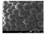
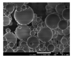
- the substantially spherical PLGA fine particles of the present invention are substantially spherical PLGA fine particles containing a physiologically active substance, having a sharp particle size distribution and an average volume reference particle size of 1 ⁇ m or more and 150 ⁇ m or less.
- the substantially spherical PLGA fine particles of the present invention appropriately adjust the initial release amount of the physiologically active substance and the release rate during the subsequent release period, and continuously release the physiologically active substance for a certain period of time in the living body effectively. It can show pharmacological effects.
- substantially spherical PLGA fine particles of the present invention a fine particle treatment is performed between a plurality of processing surfaces arranged so as to be close to each other and separated from each other, and at least one of which rotates relative to the other. Approximately spherical PLGA fine particles are produced using the processing apparatus.
- substantially spherical PLGA fine particles having few coarse particles or fine particles and a sharp particle size distribution centered on a target particle size can be efficiently produced without going through a classification step.
- the treatment liquid outlet side has a positive pressure from atmospheric pressure.
- the treatment surfaces installed facing each other have a pressure distribution, and the pressure usually drops in the direction of discharge from the treatment surfaces, and the pressure approaches the atmosphere at the treatment liquid outlet.
- the residual pressure generated at the outlet of the treatment surface is canceled, so that the treatment liquid can be stably discharged. If residual pressure remains between the treatment surfaces, the treatment liquid may flush due to pressure fluctuations at the treatment liquid discharge section, causing the generation of fine particles. This method prevents such a situation. ..
- the processing surface which is arranged in opposition to each other so that the processing apparatus can approach and separate, at least one of which rotates relative to the other, is stopped.
- Surface pressure is adjusted.
- the surface pressure is 20g / cm 2 ⁇ 250g / cm 2.
- a PLGA solution obtained by dissolving or dispersing the PLGA and the lipophilic physiologically active substance in a good PLGA solvent and a solution containing the poor PLGA solvent.
- substantially spherical PLGA fine particles are produced in a sterile environment. can do.
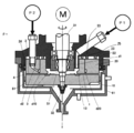
- FIG. 1 It is a substantially half-cross-sectional view of an example of a fine particle processing apparatus used in the method for producing substantially spherical PLGA fine particles of the present invention.
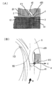
- A) is a schematic plan view of the first processing surface of the fluid processing apparatus of FIG. 1, and (B) is an enlarged view of a main part of the first processing surface.
- A) is a cross-sectional view of a second introduction portion of the fluid processing apparatus of FIG. 1, and (B) is an enlarged view of a main part of a first processing surface for explaining the second introduction portion.
- PLGA is a lactic acid / glycolic acid copolymer having a structural unit derived from lactic acid and a structural unit derived from glycolic acid.
- PLGA may contain other biodegradable macromolecules such as polylactide (PLA), polyglycolide (PGA) and the like.
- PLA polylactide
- PGA polyglycolide
- the molar ratio (L: G) of the structural unit (L) derived from lactic acid and the structural unit (G) derived from glycolic acid in PLGA is not particularly limited and may be appropriately selected depending on the intended purpose. However, 1:99 to 99: 1 is preferable, 25:75 to 99: 1 is more preferable, 30:70 to 90:10 is further preferable, and 50:50 to 85:15 is particularly preferable.
- the PLGA used for the substantially spherical PLGA fine particles of the present invention can be produced, for example, by heating lactic acid and glycolic acid under a weak reduced pressure using an ion exchange resin as a catalyst and performing condensation polymerization. At that time, lactide may be used instead of lactic acid.
- PLGA may be a commercially available product. As a commercially available product, for example, it can be purchased from Fujifilm Wako Pure Chemical Industries, Ltd., Taki Chemical Co., Ltd., Evonik Rohm GmbH, Merck, Sigma-Aldrich, and the like.
- the content of PLGA in the substantially spherical PLGA fine particles of the present invention is not particularly limited and may be appropriately selected depending on the intended purpose, but is preferably 1% by mass or more, and more preferably 30% by mass or more and 95% by mass or less. It is preferable, and 50% by mass or more and 90% by mass or less is particularly preferable.
- the substantially spherical PLGA fine particles of the present invention include PLGA and a lipophilic physiologically active substance. Further, if necessary, a dispersant and other components are contained. Physiologically active substances, dispersants, other components and the like are dispersed in the matrix of substantially spherical PLGA fine particles.
- the physiologically active substance contained in the substantially spherical PLGA particles of the present invention is not particularly limited and may be appropriately selected depending on the intended purpose. Examples thereof include pharmaceutical compounds, functional food compounds, and functional cosmetic compounds. Be done.
- the substantially spherical PLGA fine particles containing the pharmaceutical compound can be suitably used, for example, as a sustained-release pharmaceutical preparation.
- Physiologically active substances include both lipophilic and hydrophilic physiologically active substances. A lipophilic physiologically active substance is mentioned as a preferable physiologically active substance.
- the lipophilic physiologically active substance means, for example, a substance having a logP value of 3 or more in the water / octanol partition coefficient, and a physiologically active substance not included in the lipophilic physiologically active substance is classified as a hydrophilic physiologically active substance.
- the water / octanol partition coefficient can be measured according to the JISZ7260-107 (2000) flask shaking method.
- the physiologically active substance is not particularly limited as long as a sustained-release preparation is desired, and can be appropriately selected depending on the intended purpose.
- Physiologically active substances include any form such as salt and hydrate.
- Dispersants can be used to disperse the bioactive substance.
- the dispersant may be a low molecular weight dispersant or a high molecular weight dispersant polymer.
- a low molecular weight dispersant means a compound having a weight average molecular weight of less than 15,000, and a high molecular weight dispersant polymer contains repeated covalent bonds between one or more monomers and has a weight average molecular weight of less than 15,000. Means more than 15,000 compounds.
- the low molecular weight dispersant is not particularly limited as long as it is acceptable for pharmaceutical compounds, functional food compounds, functional cosmetic compounds, etc., and can be appropriately selected according to the purpose. Specific examples thereof include lipids, sugars, cyclodextrins, amino acids, organic acids, and other components. These may be used alone or in combination of two or more.
- the lipids are not particularly limited and may be appropriately selected depending on the intended purpose.
- vegetable oil for example, soybean oil, avocado oil, squalane oil).
- Sesame oil olive oil, corn oil, rapeseed oil, saflower oil, sunflower oil, etc.
- fish oil seasoning oil
- water-insoluble vitamins fatty acids, and mixtures thereof, and derivatives thereof.
- the saccharide is not particularly limited and may be appropriately selected depending on the intended purpose.
- examples thereof include ose, acarbose, water-soluble cellulose, synthetic cellulose, sugar alcohol, glycerin, sorbitol, lactitol, maltose, mannitol, xylose, erythritol, or polyol, or derivatives thereof. These may be used alone or in combination of two or more.
- the other ingredients are not particularly limited and can be appropriately selected according to the purpose, but those that can be conventionally used in medicine are preferable.
- the average volume reference particle diameter of the substantially spherical PLGA fine particles of the present invention is 1 ⁇ m or more and 150 ⁇ m or less, preferably 10 ⁇ m or more and 100 ⁇ m or less, and more preferably 20 ⁇ m or more and 75 ⁇ m or less.
- the average volume reference particle size can be measured using a laser diffraction type particle size distribution measuring device.
- the problem of initial burst occurs due to the heteroscedasticity of the physiologically active substances in the PLGA fine particles, and the particles tend to aggregate and settle, and the post-process treatment is also performed. It gets harder. If it is smaller than 1 ⁇ m, the problem of initial burst occurs remarkably.
- R. of the substantially spherical PLGA fine particles of the present invention R. of the substantially spherical PLGA fine particles of the present invention.
- S. F satisfies the equation (1). 0.1 ⁇ (RSF) ⁇ 1.7 Equation (1)
- R. S. F means (D90-D10) / D50.
- D90 represents the particle size ( ⁇ m) corresponding to the cumulative 90% by volume of the cumulative particle size distribution from the small particle side
- D50 represents the particle size ( ⁇ m) corresponding to the cumulative 50% by volume of the cumulative particle size distribution from the small particle side.
- D10 represents the particle diameter ( ⁇ m) corresponding to the cumulative 10% by volume from the small particle side of the cumulative particle size distribution.
- the particle size measurement results of the leuprolide acetate-containing microspheres obtained in Examples 1 to 5 of Patent Document 7 are shown in Table 3 of the same publication.
- the particle distribution (D10, D50 and D90) and the average particle size are as shown in Table 1 below. From these numerical values, R. S. When F was obtained, as shown in Table 1, R. S. F is 2.17 to 9.10, which greatly exceeds the range of the formula (1) in the present invention.
- the microspheres of Patent Document 7 have large variations in particle size, and the particle size distribution is not sharp and unsatisfactory.
- R. S. F can be measured using a laser diffraction type particle size distribution measuring device (SALD-7000, manufactured by Shimadzu Corporation, or Microtrack MT-3300, manufactured by Microtrack Bell). R. S. If F is larger than 1.7, it cannot be said that the particle size distribution is sharp. Such R. S. The yield of the substantially spherical PLGA fine particles of F decreases because a classification step is required.
- SALD-7000 laser diffraction type particle size distribution measuring device
- Microtrack MT-3300 manufactured by Microtrack Bell
- the substantially spherical PLGA fine particles of the present invention preferably have a coefficient of variation (Coefficient of Variation (CV value)) of 60% or less, more preferably 50% or less, still more preferably 40% or less. Even more preferably 30% or less, particularly preferably 20% or less, and particularly even more preferably 10% or less.
- CV value is calculated by "standard deviation of volume particle diameter" / "average volume particle diameter” in particle size distribution measurement.
- the substantially spherical PLGA fine particles of the present invention appropriately adjust the initial release amount of the physiologically active substance and the release rate during the subsequent release period, and continuously release the physiologically active substance for a certain period of time in the living body effectively. It can show pharmacological effects.
- a sustained-release preparation containing substantially spherical PLGA fine particles can be prepared.
- the sustained-release preparation of the present invention appropriately adjusts the initial release amount of the physiologically active substance and the release rate during the subsequent release period, and continuously releases the physiologically active substance for a certain period of time in the living body, effectively as a drug. Can show a physical effect.
- the sustained-release preparation of the present invention can be easily administered as an injection and an implant, or as a transdermal agent, directly into lesions such as intramuscular, subcutaneous, blood vessels, organs, joint cavities, and tumors. It can also be administered in various other formulation forms.
- a dispersant Teween 80, HCO-60, carboxymethyl cellulose, sodium alginate, etc.
- a preservative methylparaben, propylparaben, etc.
- an isotonic agent chloride
- It can be used as an aqueous suspension together with sodium, mannitol, sorbitol, glucose, etc., or dispersed with vegetable oils such as soybean oil, sesame oil, and corn oil to form an oil-based suspension, which is used as a sustained-release injection.
- the fine particle processing apparatus (hereinafter, also referred to as a fluid processing apparatus or simply a processing apparatus) used in the method for producing substantially spherical PLGA fine particles of the present invention will be described below with reference to FIGS. 1 to 3.
- the fine particle processing device is a processing device in which the fine particle processing is performed between a plurality of processing surfaces arranged so as to be close to each other and separated from each other, and at least one of them rotates relative to the other.
- the fine particle processing apparatus the same processing apparatus as that described in Patent Document 8 is preferably used.
- the fluid to be processed is processed in the processing space defined by at least two processing surfaces that rotate relatively.
- Another fluid to be treated, which is the first fluid to be treated is introduced into the processing space, and is independent of the flow path into which the first fluid is introduced and has an opening leading to the processing space.
- a second fluid which is the second fluid to be processed, is introduced into the processing space from the flow path, and the first fluid and the second fluid are mixed in the processing space to continuously fluidize the fluid. It is a device that performs the processing of. In other words, each of the above fluids is merged into a thin film fluid in a processing space defined by a disk-shaped processing surface facing the axial direction of rotation, and the flow to be processed is formed in the thin film fluid. It is a device that processes the body and discharges the processed fluid from the processing space. Although this device is most suitable for processing a plurality of fluids to be processed, a single fluid to be processed can also be used for processing a fluid in a processing space.
- the top and bottom of the figure correspond to the top and bottom of the device, but in the present invention, the top, bottom, front, back, left, and right only show a relative positional relationship, and do not specify an absolute position.
- R indicates a rotation direction.
- C indicates the centrifugal force direction (radial direction).
- the cylinder should not be interpreted as a mathematical cylinder, but includes a cylinder, a hollow cylinder (hereinafter referred to as a cylinder), and a cylinder having a top.
- This fine particle processing apparatus includes two first and second processing units 10 and 20 that face each other, and at least one processing unit rotates with respect to the other processing unit.
- the facing surfaces of both processing units 10 and 20 are processing surfaces, respectively.
- the first processing unit 10 includes a first processing surface 1
- the second processing unit 20 includes a second processing surface 2.
- the surfaces 1 and 2 for both treatments define the treatment space 3, and the fluids to be treated such as mixing the fluids to be treated are treated in the treatment space 3.
- the processing space 3 is an annular space, as will be described later.
- the spacing between the surfaces 1 and 2 for both treatments can be changed as appropriate, but in this embodiment, it is usually adjusted to a minute spacing of 1 mm or less, for example, about 0.1 ⁇ m to 150 ⁇ m. As a result, the fluid to be treated passing between the surfaces 1 and 2 for both treatments becomes a forced thin film fluid forced by the surfaces 1 and 2 for both treatments.
- the fine particle processing device When a plurality of fluids to be treated including the first fluid and the second fluid are treated by using this fine particle processing device, the fine particle processing device is connected to the flow path of the first fluid and is used for both treatment surfaces. It is introduced from the upstream end (inside the ring in this example) of the processing space 3 defined by 1 and 2. At the same time, the processing space 3 forms a part of the flow path of the second fluid, which is different from the first fluid. Then, in the processing space 3 between the surfaces 1 and 2 for both treatments, the fluids to be treated, such as the first fluid and the second fluid to be treated, are mixed and emulsified.
- the micronization processing apparatus includes a second holder 22 that holds the second processing unit 20, a contact surface pressure applying mechanism, a rotation drive mechanism M, a first introduction unit d1, and a second. 2
- the introduction unit d2 and the fluid pressure applying mechanisms P1 and P2 are provided.
- the second processing unit 20 is arranged above the first processing unit 10, and the lower surface of the second processing unit 20 is the second processing surface 2 for the first processing.
- the upper surface of the portion 10 is the first processing surface 1.
- the first processing portion 10 is a disk body having no central opening.
- the second processing portion 20 is an annular body, and more specifically, a ring-shaped disc.
- the processing space 3 defined between the two processing surfaces 1 and 2 is annular. It constitutes a space, that is, an annular flow path.
- the second processing unit 20 may have a disk shape without an opening in the center, provided that a fluid to be processed containing the first fluid and the second fluid can be introduced.
- the first and second processing portions 10 and 20 can be formed of a single member or a combination of a plurality of members, and the material thereof is metal, ceramics such as silicon carbide (SiC), or sintered metal. , Abrasion resistant steel, sapphire, and other metals that have been hardened, and hard materials that have been lined, coated, or plated can be used. In this embodiment, at least a part of the first and second processing surfaces 1 and 2 is mirror-polished.
- At least one of the first processing unit 10 and the second processing unit 20 is rotated relative to the other processing unit by the rotation drive mechanism M such as an electric motor.
- the drive shaft of the rotation drive mechanism M is connected to the rotation shaft 31, and in this example, the first processing unit 10 attached to the rotation shaft 31 rotates with respect to the second processing unit 20.
- the rotary shaft 31 is fixed to the center of the first processing portion 10 by a fixture 32 such as a screw, and its rear end is connected to the drive shaft of the rotary drive mechanism M to drive the rotary drive mechanism M.
- a force is transmitted to the first processing portion 10 to rotate the first processing portion 10, and a support portion 33 for axially supporting the rotating shaft 31 is provided at the center of the annular shape of the annular second holder 22. Be prepared.
- the second processing portion 20 supported by the second holder 22 may be rotated, or both may be rotated.
- At least one of the first processing unit 10 and the second processing unit 20 can approach and separate from at least one of the rotating shafts 31 in the axial direction.
- the surfaces 1 and 2 for both treatments can approach and separate from each other.
- the first processing portion 10 is fixed in the axial direction and is configured to rotate in the circumferential direction.
- the second processing portion 20 approaches and separates from the first processing portion 10 in the axial direction, and a sealing mechanism such as an O-ring 24 is used for the accommodating portion 23 provided in the second holder 22.
- the second processing unit 20 is housed so as to be infested.
- the accommodating portion 23 is a recess for accommodating a portion of the second processing portion 20 that is mainly axially opposite to the second processing surface 2 side, and exhibits a circle in a plan view, that is, is formed in an annular shape. It is a groove.
- the second processing portion 20 may be arranged in the accommodating portion 23 of the second holder 22 so that it can only be moved in parallel in the axial direction, but it can also be accommodated in a state where the clearance is increased.
- the second processing unit 20 may be held by a floating mechanism that holds the second processing portion 20 in a dimensionally displaceable manner.
- the fluids to be treated (the first fluid and the second fluid in this example) are supplied to the micronization treatment apparatus by the fluid pressure applying mechanisms P1 and P2.
- Various pumps can be used for the fluid pressure applying mechanisms P1 and P2, and the fluid to be treated can be supplied to the fine particle processing apparatus at a predetermined pressure.
- a pressure applying device provided with a pressure container can be adopted as the fluid pressure applying mechanisms P1 and P2.
- the fluid to be processed can be pumped by introducing a pressurizing gas into a pressurized container containing the fluid to be processed and pushing out the fluid to be processed by the pressure.
- the first introduction portion d1 is a flow path provided in the annular second holder 22, and one end thereof is connected to the tubular introduction space 51.
- the introduction space 51 is a cylindrical space defined by the lower surface of the support portion 33, the lower surface on the inner peripheral side of the second holder 22, the inner peripheral surface of the second processing portion 20, and the first processing surface 1.
- the second introduction portion d2 is a passage provided inside the second processing portion 20, one end of which is opened by the second processing surface 2, and this opening is directly to the processing space 3. This is the introduction opening (second introduction port d20).
- the first fluid is introduced into the processing space 3 from the first introduction portion d1 via the introduction space 51 and from the upstream end of the processing space 3 which is a gap on the inner diameter side between the processing portions 10 and 20. , This gap becomes the first introduction port d10.
- the first fluid introduced into the treatment space 3 from the first introduction port d10 becomes a thin film fluid on the first treatment surface 1 and the second treatment surface 2, and passes through the outside of both treatment portions 10 and 20.
- a second fluid pressurized to a predetermined pressure is supplied from the second introduction port d20 of the second introduction section d2 between these processing surfaces 1 and 2, and merges with the first fluid which is a thin film fluid.
- the reaction treatment is carried out mainly while or after mixing by molecular diffusion. As these treatments, only mixing by molecular diffusion may be performed. This reaction treatment may or may not be accompanied by crystallization, crystallization, precipitation and the like.
- the thin film fluid composed of the first fluid and the second fluid is discharged from the surfaces 1 and 2 for both treatments to the outside of the treatment portions 10 and 20 after the fine particle treatment.
- the fluid discharged from both the treatment surfaces 1 and 2 to the outside of both treatment portions 10 and 20 is received by the outer casing 61 arranged outside the first treatment portion 10 and subjected to the fine particle treatment. Is discharged to the outside of the system (outside the device).
- the fluid discharged from both treatment surfaces 1 and 2 to the outside of both treatment portions 10 and 20 is released from the forcing by both treatment surfaces 1 and 2 and is discharged into a wider flow path space 81.
- the fluid to be processed in the processing space 3 does not move linearly from the inside to the outside, but moves in the radial direction of the ring and the circumferential direction.
- the composite vector with the moving vector to is acting on the fluid to be processed and moves from the inside to the outside in a substantially spiral shape.
- V representative velocity
- L representative length
- ⁇ density
- ⁇ viscosity
- the space between the surfaces 1 and 2 for both treatments of the fine particle processing apparatus is usually adjusted to a minute interval of 1 mm or less, for example, about 0.1 ⁇ m to 150 ⁇ m, the fluid held between the surfaces 1 and 2 for both treatments.
- the amount of is extremely small. Therefore, the representative length L becomes very small, the centrifugal force of the thin film fluid passing between the surfaces 1 and 2 for both treatments is small, and the influence of the viscous force becomes large in the thin film fluid. Therefore, the Reynolds number becomes small, and the thin film fluid becomes a laminar flow.
- Centrifugal force is a kind of inertial force in rotational motion, and is a force from the center to the outside.
- the centrifugal force F is represented by the following equation (3).
- the contact pressure applying mechanism for applying a force acting in a direction in which the first processing surface 1 and the second processing surface 2 are brought close to each other to the processing portion.
- the contact pressure applying mechanism is provided on the second holder 22 and urges the second processing portion 20 toward the first processing portion 10.
- the contact pressure applying mechanism applies a force (in a direction approaching each other) with respect to the first processing surface 1 of the first processing unit 10 and the second processing surface 2 of the second processing unit 20.
- it is a mechanism for generating contact pressure).
- this contact surface pressure Due to the balance between this contact surface pressure and the force that separates the surfaces 1 and 2 for both treatments such as the fluid pressure by the fluid pressure applying mechanisms P1 and P2, it has a minute film thickness of 1 mm or less in nm unit to ⁇ m unit. Generates a thin film fluid. In other words, the balance of the forces keeps the distance between the surfaces 1 and 2 for both treatments at a predetermined minute distance.
- the contact pressure applying mechanism is coordinated between the accommodating portion 23 and the second processing portion 20.
- a spring 25 that urges the second processing unit 20 in a direction approaching the first processing unit 10 and an urging fluid introduction unit that introduces an urging fluid such as air or oil (shown in the figure).
- the contact surface pressure is applied by the spring 25 and the fluid pressure of the urging fluid.
- the spring 25 and the fluid pressure of the urging fluid may be any one of them, and may be another force such as magnetic force or gravity.
- the second processing portion 20 is moved by the separation force generated by the pressure and viscosity of the fluid to be processed pressurized by the fluid pressure applying mechanisms P1 and P2. 1 Move away from the processing unit 10 and leave a small gap between both processing surfaces 1 and 2. In this way, the first processing surface 1 and the second processing surface 2 are set with an accuracy of ⁇ m unit by the balance of the contact pressure and the separation force, and between the two processing surfaces 1 and 2. The minute interval is set.
- the above-mentioned separation force is generated by the fluid pressure and viscosity of the fluid to be treated, as well as the centrifugal force due to the rotation of the processing portion, the negative pressure when a negative pressure is applied to the urging fluid introduction portion, and the spring.
- the force of the spring when 25 is used as a tension spring can be mentioned.
- This contact surface pressure applying mechanism may be provided not in the second processing unit 20 but in the first processing unit 10, or may be provided in both.
- a groove-shaped recess 13 extending from the center side of the first processing portion 10 to the outside, that is, in the radial direction is formed on the first processing surface 1 of the first processing portion 10. It may be carried out.
- the planar shape of the recess 13 is a shape that curves or extends in a spiral shape on the first processing surface 1, a shape that does not show, but extends straight outward, L. It may be bent or curved in a character shape, continuous, intermittent, or branched.
- the recess 13 can be formed on both the first and second treatment surfaces 1 and 2, and can also be formed on the second treatment surface 2.
- the base end of the recess 13 reaches the introduction space 51.
- the tip of the recess 13 extends toward the outer peripheral surface side of the first processing portion 10, and the depth (cross-sectional area) thereof may be gradually decreased from the base end toward the tip.
- a flat surface 16 without the recess 13 is provided between the tip of the recess 13 and the outer peripheral surface 11 of the first processing portion 10.
- the second introduction port d20 be provided on the downstream side (outside in this example) from the recess 13 of the first processing surface 1.
- the outer diameter is larger than the point where the flow direction when the first fluid is introduced into the processing space 3 by the micropump effect is converted into the flow direction of the laminar flow in a spiral shape formed between the processing surfaces 1 and 2. It is desirable to install it at a position facing the flat surface 16 on the side.
- the distance n in the radial direction from the outermost position of the recess 13 provided on the first processing surface 1 is about 0.5 mm or more.
- a plurality of fluids to be treated are mixed by molecular diffusion under laminar flow conditions, and the fine particles and precipitation are performed.
- the peripheral speed on the outer circumference of the first treatment portion 10 is 0.3 to 35 m / sec.
- the shape of the second introduction port d20 may be a continuous opening such as a concentric circular ring shape surrounding the central opening of the second processing surface 2 which is a ring-shaped disc. , As shown in FIG. 2 (B) and FIG. 3 (B), it may be an independent opening such as a circle. Further, when the second introduction port d20 has a ring shape, the ring-shaped opening may be continuous over the entire circumference or may be partially discontinuous.
- the shape of the opening is a concentric annular shape.
- This second introduction part d2 can have a direction.
- the introduction direction of the second processing surface 2 from the second introduction port d20 is inclined at a predetermined elevation angle ( ⁇ 1) with respect to the second processing surface 2.
- This elevation angle ( ⁇ 1) is set to more than 0 degrees and less than 90 degrees, and in the case of a reaction having a faster reaction speed, it is preferably set to 1 degree or more and 45 degrees or less.
- the second introduction port d20 when it is an independent opening hole, it may have directionality in a plane along the second processing surface 2.
- the introduction direction of the second fluid is the outward direction away from the center in the radial component of the processing surface, and with respect to the rotation direction of the fluid between the relatively rotating processing surfaces.
- the components of are in the forward direction.
- it has a predetermined angle ( ⁇ 2) from the reference line g to the rotation direction R, with the line segment in the radial direction passing through the second introduction port d20 and the outward direction as the reference line g.
- This angle ( ⁇ 2) is also preferably set to more than 0 degrees and less than 90 degrees.
- the type of the fluid to be treated and the number of flow paths thereof are set to two, but may be one or three or more.
- the second fluid is introduced into the processing space 3 from the second introduction unit d2, but this introduction unit may be provided in the first processing unit 10 or both.
- a plurality of introduction portions may be prepared for one type of fluid to be treated.
- the shape, size, and number of each inlet are not particularly limited and may be appropriately changed.
- an introduction port may be provided immediately before or further upstream of the first and second processing surfaces 1 and 2.
- each flow path is hermetically sealed, and is liquid-tight (when the fluid to be treated is a liquid) and airtight (when the fluid to be treated is a gas).
- the pressure on the processing liquid outlet (outlet 4) side from the processing surface is more positive than the atmospheric pressure.
- the treatment surfaces installed facing each other have a pressure distribution, and the pressure usually drops in the direction of discharge from the treatment surfaces, and the pressure approaches the atmosphere at the treatment liquid outlet.
- the treatment liquid outlet By setting the treatment liquid outlet to a positive pressure, the residual pressure generated at the treatment surface outlet is canceled, so that the treatment liquid can be stably discharged. If residual pressure remains between the treatment surfaces, the treatment liquid may flush due to pressure fluctuations at the treatment liquid discharge section, resulting in the generation of fine particles.
- the method for producing substantially spherical PLGA fine particles of the present invention includes at least a particle forming step, and may further include a filtration sterilization step, a good solvent removing step, and other steps, if necessary.
- a processing apparatus in which the fine particle processing is performed between a plurality of processing surfaces arranged so as to be close to each other and that can be separated from each other and at least one of them rotates relative to the other. Is preferable.
- a PLGA solution obtained by dissolving or dispersing PLGA and a physiologically active substance in a good PLGA solvent and a solution containing a poor PLGA solvent are continuously charged using the above-mentioned fine particle processing apparatus. Then, emulsified particles are prepared, and a good solvent is removed from the prepared particles to precipitate substantially spherical PLGA fine particles of the present invention.
- dispersion means that the physiologically active substance is dispersed as a solid in a good solvent of PLGA, the physiologically active substance is emulsified in a good solvent of PLGA, an aqueous solution of the hydrophilic physiologically active substance and the good of PLGA. It includes forming a w / o emulsion containing a solvent and the like.
- the PLGA solution is not particularly limited as long as it is a solution in which PLGA and a physiologically active substance are dissolved or dispersed in a good solvent of PLGA, and can be appropriately selected depending on the intended purpose.
- the good solvent is not particularly limited and may be appropriately selected depending on the intended purpose. Examples thereof include halogenated aliphatic hydrocarbons, aliphatic esters, alcohols, ketones, ethers and acetonitrile. Examples of the halogenated aliphatic hydrocarbon include dichloromethane, chloroform, carbon tetrachloride, chloroethane, 2,2,2-trichloroethane and the like.
- Examples of the aliphatic ester include ethyl acetate, propyl acetate, butyl acetate and the like.
- Examples of the alcohol include alcohols having low solubility in water such as benzyl alcohol, phenyl alcohol, and n-butanol.
- Examples of the ketone include ketones having 3 to 6 carbon atoms (for example, acetone, methyl ethyl ketone, methyl isobutyl ketone, cyclohexanone, etc.).
- Examples of the ether include ethers having 2 to 6 carbon atoms (for example, dimethyl ether, methyl ethyl ether, diethyl ether, etc.).
- a solvent having low solubility in water from the viewpoint of the content of the physiologically active substance and the purpose of preventing the initial burst.
- Preferred good solvents include halogenated aliphatic hydrocarbons, ketones, and mixed solvents thereof, and more preferably dichloromethane, acetone, and mixed solvents thereof. In addition, these may be used alone or in combination of two or more.
- the particle size can be controlled by changing the solvent type and the mixing amount.
- a good solvent means a solvent having a high solubility of PLGA
- a poor solvent means a solvent having a low solubility of PLGA or an insoluble solvent.
- the good solvent and the poor solvent can be defined by, for example, the mass of PLGA that can be dissolved in 100 g of the solvent at 25 ° C.
- the good solvent is preferably a solvent that dissolves 0.1 g or more of PLGA, more preferably 0.2 g or more, and further preferably 0.5 g or more.
- the poor solvent is preferably a solvent that dissolves only 0.05 g or less of PLGA, more preferably 0.02 g or less, and further preferably 0.01 g or less.
- the poor solvent is not particularly limited and may be appropriately selected depending on the intended purpose, but water is preferable.
- the content of PLGA in the PLGA solution can be changed depending on the good solvent and the particle size of the target PLGA fine particles, and examples thereof include 1 to 30% by mass, preferably 3 to 20%.
- the mass% is mentioned, and more preferably 5 to 15% by mass is mentioned.
- the content of the physiologically active substance in the PLGA solution can be appropriately changed according to the purpose, pharmacological effect and the like.
- a stabilizer may be added to the poor solvent.
- the stabilizer is not particularly limited and may be appropriately selected depending on the intended purpose.
- polyvinyl alcohol (PVA), polyvinylpyrrolidone (PVP), carboxymethylcellulose (CMC), hydroxypropylcellulose (HPC), hydroxypropylmethylcellulose (HPMC), lecithin, polysorbate 80 and the like can be mentioned, with polyvinyl alcohol (PVA) being preferred. ..
- the concentration of the stabilizer to be added is preferably 0.01 to 20% by mass, and more preferably 5% by mass or less.
- Preferred poor solvents include, for example, an aqueous PVA solution.
- the PLGA solution and the solution containing a poor solvent include those in which a stirrer of various shapes such as rod, plate, and propeller is rotated in a tank, and those equipped with a screen that rotates relative to the stirrer.
- a preparation device such as a rotary disperser that realizes uniform mixing by applying a shearing force to the fluid.
- the stirrer disclosed in Japanese Patent No. 5147091 can be applied.
- the rotary disperser may be a batch type or a continuous type.
- the fluid may be continuously supplied and discharged to the stirring tank, or may be performed by using a continuous mixer without using the stirring tank.
- the stirring energy can be appropriately controlled by using a known stirring machine or stirring means.
- the stirring energy is described in detail in Japanese Patent Application Laid-Open No. 04-114725 by the present applicant.
- the stirring method in the present invention is not particularly limited, but it can be carried out by using various shearing type, friction type, high pressure jet type, ultrasonic type and other stirring machines, melting machines, emulsifying machines, dispersers, hojinizers and the like. ..
- Ultra Tarax made by IKA
- Polytron made by Kinematica
- TK Homo Mixer made by Primix
- Ebara Milder made by Ebara Corporation
- TK Homomic Line Flow made by Primix
- Colloid Mill Shinko Pan Continuous emulsifiers such as tech
- slasher Neippon Coke Industries
- trigonal wet pulverizer Mitsubishi wet pulverizer
- Cavitron Eurotech
- fine flow mill Pacific Kiko
- Clairemix (M) -Batch type or continuous dual-purpose emulsifiers such as (manufactured by Technique) and Claire Mix Dissolver (manufactured by M. Technic)
- M Manufacturing Dissolver
- the stirring process is provided with a stirring blade that rotates at high speed, a screen is provided on the outside of the stirring blade, and a stirrer that discharges fluid as a jet flow from the opening of the screen, particularly the above-mentioned Cumix ( It is desirable to use M-Technique) or Mariemix Dissolver (M-Technique).
- the contact pressure is preferably 20 g / cm 2 to 250 g / cm 2 .
- the contact pressure is lower than 20 g / cm 2 , the thin film is not stable and the particle size distribution becomes wide. It was found that if the contact pressure is higher than 250 g / cm 2, it becomes difficult to adjust the target particle size. More preferably, 50 g / cm 2 to 200 g / cm 2 is mentioned, and more preferably 80 g / cm 2 to 150 g / cm 2 is mentioned.
- a method for preventing the coalescence it is preferable to put a solution containing a poor solvent in advance in the solution discharge liquid recovery tank and stir gently. By performing stirring, coalescence of PLGA fine particles can be further suppressed.
- a rotary disperser is preferable, and a Clairemix dissolver (manufactured by M-Technique) is preferable. It is not particularly limited as long as it can flow the whole gently. If the stirring is strong, the PLGA emulsified particles may be broken and the distribution width may be widened.
- the particle forming step can be preferably carried out according to the above description, and substantially spherical PLGA fine particles can be produced.
- the physiologically active substance is a hydrophilic physiologically active substance
- the hydrophilic physiologically active substance is dispersed in a good solvent of PLGA by using, for example, a dispersant, and the particle formation step is similarly carried out to carry out a substantially spherical PLGA. Fine particles can be produced.
- the physiologically active substance is a hydrophilic physiologically active substance
- a solution in which the hydrophilic physiologically active substance is dissolved in an aqueous solvent such as water together with a stabilizer, if necessary, and PLGA is dissolved in a good solvent of PLGA can also be used as a PLGA solution and the above-mentioned particle forming step can be carried out by using the above-mentioned fine particle processing apparatus.
- an intermittent shaking method for the preparation of the w / o emulsion, an intermittent shaking method, a propeller type stirrer, a method using a mixer using a turbine type stirrer, a colloid mill method, a homogenizer method, and an ultrasonic irradiation method can be used.
- the PLGA solution which is the w / o emulsion and the solution containing the poor solvent of PLGA are continuously charged to prepare emulsified particles as a w / o / w emulsion. It is carried out by precipitating substantially spherical PLGA fine particles of the present invention as microcapsules by removing a good solvent from the particles.
- the PLGA fine particles as the microcapsules can be used as they are, but they can also be solidified by adding excipients (mannitol, sorbitol, lactose, glucose, etc.), redispersing, and then freeze-drying or spray-drying. it can. By adding distilled water for injection or an appropriate dispersion medium to the solidified PLGA fine particles at the time of use, a more stable sustained-release injection can be obtained.
- excipients mannitol, sorbitol, lactose, glucose, etc.
- the solution containing the poor solvent can be sterilized by filtration using a hydrophilic filter, and the PLGA solution containing PLGA and a physiologically active substance can be sterilized by filtration using a hydrophobic filter.
- the pore size of the filter used for filtration is preferably 0.1 ⁇ m to 0.45 ⁇ m, more preferably 0.2 ⁇ m.
- the above-mentioned filtration sterilization filter is not particularly limited and can be appropriately selected according to the purpose.
- hydrophilic filters such as polyvinylidene fluoride (PVDF) and polyether sulfone can be mentioned.
- PVDF polyvinylidene fluoride
- PTFE polytetrafluoroethylene
- the material is not limited to the materials described here, and it is necessary to select the material according to the adsorption of the drug and the solvent type.
- the good solvent is removed from the emulsified particles containing PLGA and a physiologically active substance.
- the good solvent removing step is not particularly limited as long as the good solvent can be removed from the liquid containing the emulsified particles, and can be appropriately selected depending on the intended purpose.
- the good solvent is evaporated from the liquid by at least one of heating the liquid with stirring, flowing a gas such as nitrogen on the liquid surface of the liquid, and depressurizing the liquid. Examples include a method of removing.
- Examples of other steps include solvent composition preparation, classification step, particle washing step, and the like. Normally, coarse powder cutting and fine powder cutting are performed in the classification step, but the particles produced in the present invention do not need to be substantially classified. However, the classification step may be included just in case.
- substantially spherical PLGA fine particles having an average volume reference particle diameter of 1 ⁇ m or more and 150 ⁇ m or less and 0.1 ⁇ (RSF) ⁇ 1.7 are produced. Can be manufactured.
- Example 1 ⁇ Preparation of PLGA solution and PVA aqueous solution> Three kinds of mixed solvents were prepared by mixing dichloromethane (manufactured by Kanto Chemical Co., Inc.) and acetone (manufactured by Kanto Chemical Co., Inc.) at a mixing ratio (W / W) of 7: 3, 1: 1 and 3: 7. Add the above three types of mixed solvents so that the lactic acid / glycolic acid copolymer (PLGA7520, manufactured by Fujifilm Wako Pure Chemical Industries, Ltd.) is 7% by mass, and use the high-speed rotary disperser Clairemix Dissolver (manufactured by M-Technique). To obtain three types of PLGA solutions.
- the fluid processing apparatus described in JP-A-2011-189348 is the apparatus described in FIG. 25 of the same publication, and the opening at the center of the processing surface 2 in which the second introduction port d20 is a ring-shaped disk. It has a concentric ring shape that surrounds the surface.
- the prepared PVA aqueous solution is introduced between the first introduction section d1 and the treatment surfaces 1 and 2 at about 0.04 to 0.05 MPaG, 50 mL / min, 30 ° C., and the treatment section 10 is introduced.
- PLGA emulsified particle dispersion A fluid containing PLGA emulsified particles (hereinafter referred to as PLGA emulsified particle dispersion) was discharged from the processing surfaces 1 and 2 of the micronization treatment apparatus between the treatment surfaces 1 and 2.
- the PLGA emulsified particle dispersion was collected in a recovery tank via an outer casing 61 for collecting the discharged PLGA emulsified particle dispersion.
- the discharged liquid was desolvated by a nitrogen flow for 4 hours while stirring at 200 rpm (peripheral speed 4.7 m / sec) using a Clairemix dissolver (manufactured by M-Technique). Then, the good solvent was further removed under reduced pressure with an evaporator to obtain a suspension containing PLGA fine particles (PLGA particle suspension).
- Example 2 ⁇ Preparation of PLGA solution and PVA aqueous solution> Dichloromethane (manufactured by Kanto Chemical Co., Inc.) was added so that the lactic acid / glycolic acid copolymer (Resomer RG504, manufactured by Ebony) was 20% by mass, and dissolved using a high-speed rotary disperser Clairemix Dissolver (manufactured by M-Technique). , PLGA solution was obtained. Then, filtration was performed with a 0.2 ⁇ m air vent filter ( ⁇ 62, manufactured by Merck).
- Ion-exchanged water was added so that polyvinyl alcohol (PVA, EG-40P, manufactured by Nippon Synthetic Chemical Industry Co., Ltd.) was 1.5% by mass, and dissolved using a high-speed rotary disperser Clairemix (manufactured by M-Technique). An aqueous PVA solution was obtained. Then, filtration was performed with a hydrophilic PVDF membrane filter ( ⁇ 47, manufactured by Merck). A PVA aqueous solution was placed in advance in a tank for collecting PLGA emulsified particles, and the mixture was stirred to the extent that the liquid level moved.
- PVA polyvinyl alcohol
- EG-40P manufactured by Nippon Synthetic Chemical Industry Co., Ltd.
- the fluid processing apparatus described in JP-A-2011-189348 is the apparatus described in FIG. 25 of the same publication, and the opening at the center of the processing surface 2 in which the second introduction port d20 is a ring-shaped disk. It has a concentric ring shape that surrounds the surface.
- the prepared PVA aqueous solution is introduced between the first introduction section d1 and the treatment surfaces 1 and 2 at about 0.04 to 0.05 MPaG, 50 mL / min, 30 ° C., and the treatment section 10 is introduced.
- PLGA emulsified particle dispersion A fluid containing PLGA emulsified particles (hereinafter referred to as PLGA emulsified particle dispersion) was discharged from the processing surfaces 1 and 2 of the micronization treatment apparatus between the treatment surfaces 1 and 2.
- the PLGA emulsified particle dispersion was collected in a recovery tank via an outer casing 61 for collecting the discharged PLGA emulsified particle dispersion.
- Example 3 A PLGA fine particle suspension was prepared under the same conditions as in Example 2 except that the recovery tank was subjected to 0.01 MPaG pressure and the discharged liquid was collected by maintaining positive pressure.
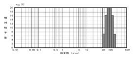
- the average volume reference particle diameter of the obtained PLGA fine particles was 50.655 ⁇ m, and R.I. S. F was 0.99.
- Example 4 From Example 2, the liquid feed temperature of the PVA aqueous solution is 24 ° C., the liquid feed temperature of the PLGA solution is 25 ° C., the liquid feed flow rate is 8 mL / min, and the rotation speed of the processing unit 10 is 1,500 rpm (peripheral speed 3.93 m /). Seconds), changed to.
- a PLGA particle suspension was prepared under the same conditions as in Example 1 except for the conditions.
- the average volume-based particle diameter of the obtained PLGA particles was 88.435 ⁇ m, and the RSF was 0.89.
- Example 5 A PLGA particle suspension was prepared under the same conditions as in Example 4 except that the pressure between the treatment surfaces was changed to 87.8 g / cm 2 .
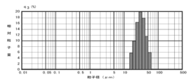
- the average volume reference particle diameter of the obtained PLGA particles was 24.793 ⁇ m, and R.M. S. F was 1.22.
- Example 6 A PLGA particle suspension was prepared under the same conditions as in Example 1 except that the rotation speed of the processing unit 10 when the PVA aqueous solution and the PLGA solution were mixed was set to 5,000 rpm (peripheral speed 19.64 m / sec). The average volume reference particle diameter of the obtained PLGA particles was 3.232 ⁇ m, and R.I. S. F was 1.16.
- Example 7 A PLGA solution was prepared by adding progesterone as a physiologically active substance. Other than that, it was carried out under the same conditions as in Example 3.
- the average volume reference particle diameter of the obtained PLGA particles was 48.925 ⁇ m, and R.I. S. F is 0.86. With or without bioactive substances, particle size and R. S. No major changes were seen in F.
- Example 1 For the preparation of the PVA aqueous solution and the PLGA solution, the solutions prepared under the same conditions as in Example 2 were used. While stirring 300 mL of the PVA aqueous solution with a Clairemix dissolver (manufactured by M-Technique) at a rotation speed of 2,000 rpm (peripheral speed 3.14 m / sec) and 25 ° C., the PLGA solution was added dropwise at 8 mL / min for 6 minutes. The mixture was stirred for 5 minutes. Then, the rotation speed was changed to such that the liquid level moved, nitrogen gas was flowed, dichloromethane was removed over 12 hours, and a suspension containing PLGA fine particles (PLGA particle suspension) was obtained. The average volume reference particle diameter of the obtained PLGA particles was 31.86 ⁇ m, and R.I. S. F was 1.90.
- Example 2 For the preparation of the PVA aqueous solution and the PLGA solution, the solutions prepared under the same conditions as in Example 2 were used. While stirring 300 mL of the PVA aqueous solution with Clairemix (manufactured by M-Technique) at a rotation speed of 2,000 rpm (peripheral speed 3.14 m / sec) and 25 ° C., the PLGA solution was added dropwise at 8 mL / min for 6 minutes, and 5 Stir for minutes. Then, the rotation speed was changed to such that the liquid level moved, nitrogen gas was flowed, dichloromethane was removed over 12 hours, and a suspension containing PLGA fine particles (PLGA particle suspension) was obtained. The average volume reference particle diameter of the obtained PLGA particles was 5.353 ⁇ m, and R.M. S. F was 1.81.
- Example 3 For the preparation of the PVA aqueous solution and the PLGA solution, the solutions prepared under the same conditions as in Example 2 were used. While treating 50 mL of the PVA aqueous solution with an ultrasonic disperser GSD50 (manufactured by Ginsen), the PLGA solution was added dropwise at 8 mL / min for 1 minute, and the treatment was carried out as it was for 5 minutes. Then, while stirring with a stirrer to the extent that the liquid surface moved, nitrogen gas was flown and dichloromethane was removed over 12 hours to obtain a suspension containing PLGA fine particles (PLGA particle suspension). The average volume-based particle diameter of the obtained PLGA particles was 6.584 ⁇ m, and R.M. S. F was 2.53.
- Example 4 For the preparation of the PVA aqueous solution and the PLGA solution, the solutions prepared under the same conditions as in Example 2 were used. While stirring 300 mL of the PVA aqueous solution with a polytron homogenizer PT1200E (manufactured by KINEMATICA) at 25 ° C., the PLGA solution was added dropwise at 8 mL / min for 6 minutes, and the mixture was stirred as it was for 5 minutes. Then, the rotation speed was changed to such that the liquid level moved, nitrogen gas was flowed, dichloromethane was removed over 12 hours, and a suspension containing PLGA fine particles (PLGA particle suspension) was obtained. The average volume reference particle diameter of the obtained PLGA particles was 8.962 ⁇ m, and R.I. S. F was 3.85.
- Comparative Example 5 From Comparative Example 3, the stirrer was changed to a homomixer HM-310 (manufactured by AS ONE). Other conditions were the same as in Comparative Example 3.
- the average volume-based particle diameter of the obtained PLGA particles was 9.126 ⁇ m, and R.I. S. F was 4.38.
- the particle size distribution is sharp around the target particle size, and the average volume reference particle size is 1 ⁇ m or more and 150 ⁇ m or less.
Landscapes
- Health & Medical Sciences (AREA)
- Chemical & Material Sciences (AREA)
- Engineering & Computer Science (AREA)
- Life Sciences & Earth Sciences (AREA)
- Bioinformatics & Cheminformatics (AREA)
- Medicinal Chemistry (AREA)
- Epidemiology (AREA)
- Pharmacology & Pharmacy (AREA)
- Animal Behavior & Ethology (AREA)
- General Health & Medical Sciences (AREA)
- Public Health (AREA)
- Veterinary Medicine (AREA)
- Inorganic Chemistry (AREA)
- Proteomics, Peptides & Aminoacids (AREA)
- Organic Chemistry (AREA)
- Chemical Kinetics & Catalysis (AREA)
- Polymers & Plastics (AREA)
- Dispersion Chemistry (AREA)
- Dermatology (AREA)
- Neurosurgery (AREA)
- Biomedical Technology (AREA)
- Medicinal Preparation (AREA)
- Medicines That Contain Protein Lipid Enzymes And Other Medicines (AREA)
- Pharmaceuticals Containing Other Organic And Inorganic Compounds (AREA)
Abstract
Priority Applications (6)
| Application Number | Priority Date | Filing Date | Title |
|---|---|---|---|
| US17/431,566 US20220133632A1 (en) | 2019-03-14 | 2019-03-14 | Plga microparticles, a sustained release formulation thereof and a production method thereof |
| KR1020217031247A KR102792825B1 (ko) | 2019-03-14 | 2019-03-14 | Plga 미립자, 그 서방성 제제 및 그 제조 방법 |
| EP19919052.1A EP3939575B1 (fr) | 2019-03-14 | 2019-03-14 | Microparticules de plga, formulation à libération prolongée de celles-ci et leur procédé de fabrication |
| CN201980093053.3A CN113490488A (zh) | 2019-03-14 | 2019-03-14 | Plga微粒子、其缓释制剂以及其制造方法 |
| JP2020538154A JP6788171B1 (ja) | 2019-03-14 | 2019-03-14 | Plga微粒子、その徐放性製剤及びその製造方法 |
| PCT/JP2019/010618 WO2020183718A1 (fr) | 2019-03-14 | 2019-03-14 | Microparticules de plga, formulation à libération prolongée de celles-ci et leur procédé de fabrication |
Applications Claiming Priority (1)
| Application Number | Priority Date | Filing Date | Title |
|---|---|---|---|
| PCT/JP2019/010618 WO2020183718A1 (fr) | 2019-03-14 | 2019-03-14 | Microparticules de plga, formulation à libération prolongée de celles-ci et leur procédé de fabrication |
Publications (1)
| Publication Number | Publication Date |
|---|---|
| WO2020183718A1 true WO2020183718A1 (fr) | 2020-09-17 |
Family
ID=72427034
Family Applications (1)
| Application Number | Title | Priority Date | Filing Date |
|---|---|---|---|
| PCT/JP2019/010618 Ceased WO2020183718A1 (fr) | 2019-03-14 | 2019-03-14 | Microparticules de plga, formulation à libération prolongée de celles-ci et leur procédé de fabrication |
Country Status (6)
| Country | Link |
|---|---|
| US (1) | US20220133632A1 (fr) |
| EP (1) | EP3939575B1 (fr) |
| JP (1) | JP6788171B1 (fr) |
| KR (1) | KR102792825B1 (fr) |
| CN (1) | CN113490488A (fr) |
| WO (1) | WO2020183718A1 (fr) |
Cited By (2)
| Publication number | Priority date | Publication date | Assignee | Title |
|---|---|---|---|---|
| US20240197717A1 (en) * | 2021-11-18 | 2024-06-20 | Inventage Lab Inc. | Sustained-release injectable composition containing naltrexone and method for preparing same |
| EP4420657A4 (fr) * | 2021-12-03 | 2025-05-14 | Inventage Lab Inc. | Microparticules contenant du leuprolide, et leur procédé de préparation |
Families Citing this family (3)
| Publication number | Priority date | Publication date | Assignee | Title |
|---|---|---|---|---|
| JPWO2023170962A1 (fr) * | 2022-03-11 | 2023-09-14 | ||
| WO2025230821A1 (fr) * | 2024-04-29 | 2025-11-06 | Avidence Therapeutics, Inc. | Formulation de finastéride injectable à base de microsphères |
| CN118725981A (zh) * | 2024-07-31 | 2024-10-01 | 广州馨誉香料有限公司 | 一种改善香料或香料组合物性能的方法 |
Citations (17)
| Publication number | Priority date | Publication date | Assignee | Title |
|---|---|---|---|---|
| JPS5147091B2 (fr) | 1971-09-30 | 1976-12-13 | ||
| JPH04114725A (ja) | 1990-09-01 | 1992-04-15 | M Technic Kk | 撹拌機及び流体の撹拌方法 |
| JP2653255B2 (ja) | 1990-02-13 | 1997-09-17 | 武田薬品工業株式会社 | 長期徐放型マイクロカプセル |
| JP2001512461A (ja) * | 1997-02-13 | 2001-08-21 | オークウッド ラボラトリーズ エル.エル.シィ. | 連続ミクロスフェア製法 |
| JP2004049957A (ja) * | 2002-07-16 | 2004-02-19 | M Technique Co Ltd | 分散乳化装置及び分散乳化方法 |
| JP2005015476A (ja) | 2003-06-03 | 2005-01-20 | Santen Pharmaceut Co Ltd | 微粒子の製造法 |
| JP2005035994A (ja) | 2003-06-26 | 2005-02-10 | Peptron Co Ltd | 徐放性マイクロスフェアの混合剤型を連続単一工程で製造する方法 |
| JP2006131577A (ja) | 2004-11-09 | 2006-05-25 | Ltt Bio-Pharma Co Ltd | 異なる粒子径を有する薬物封入ナノ粒子の作製方法および当該方法で得られたナノ粒子 |
| JP2009132871A (ja) | 2007-11-09 | 2009-06-18 | M Technique Co Ltd | 樹脂微粒子水分散体の製造方法及びこの製造方法にて得られた樹脂微粒子水分散体、樹脂微粒子 |
| JP2011189348A (ja) | 2007-07-06 | 2011-09-29 | M Technique Co Ltd | 強制超薄膜回転式処理法を用いた微粒子の製造方法 |
| JP4856752B2 (ja) | 2009-11-30 | 2012-01-18 | ホソカワミクロン株式会社 | 薬物含有ナノ粒子の製造方法 |
| JP2014224114A (ja) | 2013-05-15 | 2014-12-04 | シージェイ チェイルジェダン コーポレーションCj Cheiljedang Corporation | 連続工程のマイクロスフェアの製造方法及びそれにより製造されたマイクロスフェア |
| JP2016506923A (ja) * | 2013-01-24 | 2016-03-07 | ピエール・ファーブル・メディカマン・エス・ア・エスPierre Fabre Medicament S.A.S. | カプセル化アンタゴmirを含む組成物 |
| WO2016039359A1 (fr) * | 2014-09-10 | 2016-03-17 | 第一三共株式会社 | Composition pharmaceutique à libération prolongée destinée au traitement et à la prévention de maladies ophtalmiques |
| JP2017511371A (ja) * | 2014-04-16 | 2017-04-20 | シャンドン ルイ ファーマシューティカル カンパニー リミテッド | エクセナチド含有組成物及びその製造方法 |
| WO2017147285A1 (fr) * | 2016-02-23 | 2017-08-31 | Biodelivery Sciences International, Inc. | Microsphères de buprénorphine à libération prolongée (srbm) et leurs méthodes d'utilisation |
| JP2018052922A (ja) | 2016-09-27 | 2018-04-05 | 株式会社リコー | Plga微粒子、plga微粒子の製造方法、及びplga微粒子の製造装置 |
Family Cites Families (5)
| Publication number | Priority date | Publication date | Assignee | Title |
|---|---|---|---|---|
| CN101795772B (zh) * | 2007-07-06 | 2013-09-18 | M技术株式会社 | 使用强制超薄膜旋转式处理法的纳米粒子的制造方法 |
| JP2014050843A (ja) * | 2013-12-17 | 2014-03-20 | M Technique Co Ltd | 微粒子の製造方法 |
| US20150209342A1 (en) * | 2014-01-28 | 2015-07-30 | Allergan, Inc. | Topical retinoid formulations, processes for making and methods of use |
| US10179111B2 (en) * | 2014-03-07 | 2019-01-15 | University of Pittsburgh—of the Commonwealth System of Higher Education | Treating soft tissue via controlled drug release |
| US20180085314A1 (en) * | 2016-09-27 | 2018-03-29 | Tadahiko MORINAGA | Particulate poly(lactic-co-glycolic) acid, method for manufacturing particulate poly(lactic-co-glycolic) acid, and particulate poly(lactic-co-glycolic) acid manufacturing apparatus |
-
2019
- 2019-03-14 EP EP19919052.1A patent/EP3939575B1/fr active Active
- 2019-03-14 KR KR1020217031247A patent/KR102792825B1/ko active Active
- 2019-03-14 JP JP2020538154A patent/JP6788171B1/ja active Active
- 2019-03-14 US US17/431,566 patent/US20220133632A1/en active Pending
- 2019-03-14 WO PCT/JP2019/010618 patent/WO2020183718A1/fr not_active Ceased
- 2019-03-14 CN CN201980093053.3A patent/CN113490488A/zh active Pending
Patent Citations (17)
| Publication number | Priority date | Publication date | Assignee | Title |
|---|---|---|---|---|
| JPS5147091B2 (fr) | 1971-09-30 | 1976-12-13 | ||
| JP2653255B2 (ja) | 1990-02-13 | 1997-09-17 | 武田薬品工業株式会社 | 長期徐放型マイクロカプセル |
| JPH04114725A (ja) | 1990-09-01 | 1992-04-15 | M Technic Kk | 撹拌機及び流体の撹拌方法 |
| JP2001512461A (ja) * | 1997-02-13 | 2001-08-21 | オークウッド ラボラトリーズ エル.エル.シィ. | 連続ミクロスフェア製法 |
| JP2004049957A (ja) * | 2002-07-16 | 2004-02-19 | M Technique Co Ltd | 分散乳化装置及び分散乳化方法 |
| JP2005015476A (ja) | 2003-06-03 | 2005-01-20 | Santen Pharmaceut Co Ltd | 微粒子の製造法 |
| JP2005035994A (ja) | 2003-06-26 | 2005-02-10 | Peptron Co Ltd | 徐放性マイクロスフェアの混合剤型を連続単一工程で製造する方法 |
| JP2006131577A (ja) | 2004-11-09 | 2006-05-25 | Ltt Bio-Pharma Co Ltd | 異なる粒子径を有する薬物封入ナノ粒子の作製方法および当該方法で得られたナノ粒子 |
| JP2011189348A (ja) | 2007-07-06 | 2011-09-29 | M Technique Co Ltd | 強制超薄膜回転式処理法を用いた微粒子の製造方法 |
| JP2009132871A (ja) | 2007-11-09 | 2009-06-18 | M Technique Co Ltd | 樹脂微粒子水分散体の製造方法及びこの製造方法にて得られた樹脂微粒子水分散体、樹脂微粒子 |
| JP4856752B2 (ja) | 2009-11-30 | 2012-01-18 | ホソカワミクロン株式会社 | 薬物含有ナノ粒子の製造方法 |
| JP2016506923A (ja) * | 2013-01-24 | 2016-03-07 | ピエール・ファーブル・メディカマン・エス・ア・エスPierre Fabre Medicament S.A.S. | カプセル化アンタゴmirを含む組成物 |
| JP2014224114A (ja) | 2013-05-15 | 2014-12-04 | シージェイ チェイルジェダン コーポレーションCj Cheiljedang Corporation | 連続工程のマイクロスフェアの製造方法及びそれにより製造されたマイクロスフェア |
| JP2017511371A (ja) * | 2014-04-16 | 2017-04-20 | シャンドン ルイ ファーマシューティカル カンパニー リミテッド | エクセナチド含有組成物及びその製造方法 |
| WO2016039359A1 (fr) * | 2014-09-10 | 2016-03-17 | 第一三共株式会社 | Composition pharmaceutique à libération prolongée destinée au traitement et à la prévention de maladies ophtalmiques |
| WO2017147285A1 (fr) * | 2016-02-23 | 2017-08-31 | Biodelivery Sciences International, Inc. | Microsphères de buprénorphine à libération prolongée (srbm) et leurs méthodes d'utilisation |
| JP2018052922A (ja) | 2016-09-27 | 2018-04-05 | 株式会社リコー | Plga微粒子、plga微粒子の製造方法、及びplga微粒子の製造装置 |
Non-Patent Citations (1)
| Title |
|---|
| See also references of EP3939575A4 |
Cited By (3)
| Publication number | Priority date | Publication date | Assignee | Title |
|---|---|---|---|---|
| US20240197717A1 (en) * | 2021-11-18 | 2024-06-20 | Inventage Lab Inc. | Sustained-release injectable composition containing naltrexone and method for preparing same |
| JP2024541381A (ja) * | 2021-11-18 | 2024-11-08 | インベンテージ ラボ インコーポレイテッド | ナルトレキソンを含む徐放性注射用組成物およびその製造方法 |
| EP4420657A4 (fr) * | 2021-12-03 | 2025-05-14 | Inventage Lab Inc. | Microparticules contenant du leuprolide, et leur procédé de préparation |
Also Published As
| Publication number | Publication date |
|---|---|
| JP6788171B1 (ja) | 2020-11-25 |
| EP3939575A1 (fr) | 2022-01-19 |
| JPWO2020183718A1 (ja) | 2021-03-25 |
| KR20210138630A (ko) | 2021-11-19 |
| EP3939575A4 (fr) | 2022-10-26 |
| CN113490488A (zh) | 2021-10-08 |
| EP3939575B1 (fr) | 2026-07-01 |
| KR102792825B1 (ko) | 2025-04-11 |
| US20220133632A1 (en) | 2022-05-05 |
Similar Documents
| Publication | Publication Date | Title |
|---|---|---|
| JP6788171B1 (ja) | Plga微粒子、その徐放性製剤及びその製造方法 | |
| US6966990B2 (en) | Composite particles and method for preparing | |
| JP2003500202A (ja) | マイクロミキサによって形態学的に均一なマイクロ粒子およびナノ粒子を製造する方法 | |
| JP6810502B1 (ja) | 生理活性物質が均一に分散されたマイクロスフェアー及びそれを含有する徐放性製剤 | |
| Kucuk et al. | Microfluidic preparation of polymer nanospheres | |
| JP6852943B1 (ja) | 主剤が均一に分散されたマイクロスフェアー及びそれを含有する徐放性製剤 | |
| Padalkar et al. | Microparticles: an approach for betterment of drug delivery system | |
| US20230346706A1 (en) | Biologically active substance uniformly dispersed microsphere and a sustained release formulation comprising the same | |
| Liu et al. | Tailoring particle microstructures via supercritical CO2 processes for particular drug delivery | |
| Sujan et al. | A Review on Methods of Preparation and Characterisation of the solid Lipid Nanoparticles | |
| Schneider et al. | Use of hydrodynamic flow focusing for the generation of biodegradable camptothecin‐loaded polymer microspheres | |
| Ubgade et al. | Nanosuspensions as Nanomedicine: Current Status and Future Prospects | |
| Nikam et al. | Nanocrystal drug delivery system: A review | |
| Nuchuchua | Supercritical carbon dioxide spray drying for the production of stable dried protein | |
| WO2007000842A1 (fr) | Composition de dispersion de granules, procede de production de ceux-ci et materiau et medicament granulaire |
Legal Events
| Date | Code | Title | Description |
|---|---|---|---|
| ENP | Entry into the national phase |
Ref document number: 2020538154 Country of ref document: JP Kind code of ref document: A |
|
| 121 | Ep: the epo has been informed by wipo that ep was designated in this application |
Ref document number: 19919052 Country of ref document: EP Kind code of ref document: A1 |
|
| NENP | Non-entry into the national phase |
Ref country code: DE |
|
| ENP | Entry into the national phase |
Ref document number: 20217031247 Country of ref document: KR Kind code of ref document: A |
|
| WWE | Wipo information: entry into national phase |
Ref document number: 2019919052 Country of ref document: EP |
|
| ENP | Entry into the national phase |
Ref document number: 2019919052 Country of ref document: EP Effective date: 20211014 |
|
| WWG | Wipo information: grant in national office |
Ref document number: 2019919052 Country of ref document: EP |