WO2020183829A1 - 作業機械 - Google Patents
作業機械 Download PDFInfo
- Publication number
- WO2020183829A1 WO2020183829A1 PCT/JP2019/048445 JP2019048445W WO2020183829A1 WO 2020183829 A1 WO2020183829 A1 WO 2020183829A1 JP 2019048445 W JP2019048445 W JP 2019048445W WO 2020183829 A1 WO2020183829 A1 WO 2020183829A1
- Authority
- WO
- WIPO (PCT)
- Prior art keywords
- state
- work machine
- operator
- display
- controller
- Prior art date
- Legal status (The legal status is an assumption and is not a legal conclusion. Google has not performed a legal analysis and makes no representation as to the accuracy of the status listed.)
- Ceased
Links
Images



Classifications
-
- E—FIXED CONSTRUCTIONS
- E02—HYDRAULIC ENGINEERING; FOUNDATIONS; SOIL SHIFTING
- E02F—DREDGING; SOIL-SHIFTING
- E02F9/00—Component parts of dredgers or soil-shifting machines, not restricted to one of the kinds covered by groups E02F3/00 - E02F7/00
- E02F9/24—Safety devices, e.g. for preventing overload
-
- E—FIXED CONSTRUCTIONS
- E02—HYDRAULIC ENGINEERING; FOUNDATIONS; SOIL SHIFTING
- E02F—DREDGING; SOIL-SHIFTING
- E02F9/00—Component parts of dredgers or soil-shifting machines, not restricted to one of the kinds covered by groups E02F3/00 - E02F7/00
- E02F9/26—Indicating devices
-
- B—PERFORMING OPERATIONS; TRANSPORTING
- B60—VEHICLES IN GENERAL
- B60K—ARRANGEMENT OR MOUNTING OF PROPULSION UNITS OR OF TRANSMISSIONS IN VEHICLES; ARRANGEMENT OR MOUNTING OF PLURAL DIVERSE PRIME-MOVERS IN VEHICLES; AUXILIARY DRIVES FOR VEHICLES; INSTRUMENTATION OR DASHBOARDS FOR VEHICLES; ARRANGEMENTS IN CONNECTION WITH COOLING, AIR INTAKE, GAS EXHAUST OR FUEL SUPPLY OF PROPULSION UNITS IN VEHICLES
- B60K26/00—Arrangement or mounting of propulsion-unit control devices in vehicles
- B60K26/02—Arrangement or mounting of propulsion-unit control devices in vehicles of initiating means or elements
-
- B—PERFORMING OPERATIONS; TRANSPORTING
- B60—VEHICLES IN GENERAL
- B60K—ARRANGEMENT OR MOUNTING OF PROPULSION UNITS OR OF TRANSMISSIONS IN VEHICLES; ARRANGEMENT OR MOUNTING OF PLURAL DIVERSE PRIME-MOVERS IN VEHICLES; AUXILIARY DRIVES FOR VEHICLES; INSTRUMENTATION OR DASHBOARDS FOR VEHICLES; ARRANGEMENTS IN CONNECTION WITH COOLING, AIR INTAKE, GAS EXHAUST OR FUEL SUPPLY OF PROPULSION UNITS IN VEHICLES
- B60K35/00—Instruments specially adapted for vehicles; Arrangement of instruments in or on vehicles
- B60K35/10—Input arrangements, i.e. from user to vehicle, associated with vehicle functions or specially adapted therefor
-
- B—PERFORMING OPERATIONS; TRANSPORTING
- B60—VEHICLES IN GENERAL
- B60K—ARRANGEMENT OR MOUNTING OF PROPULSION UNITS OR OF TRANSMISSIONS IN VEHICLES; ARRANGEMENT OR MOUNTING OF PLURAL DIVERSE PRIME-MOVERS IN VEHICLES; AUXILIARY DRIVES FOR VEHICLES; INSTRUMENTATION OR DASHBOARDS FOR VEHICLES; ARRANGEMENTS IN CONNECTION WITH COOLING, AIR INTAKE, GAS EXHAUST OR FUEL SUPPLY OF PROPULSION UNITS IN VEHICLES
- B60K35/00—Instruments specially adapted for vehicles; Arrangement of instruments in or on vehicles
- B60K35/20—Output arrangements, i.e. from vehicle to user, associated with vehicle functions or specially adapted therefor
- B60K35/28—Output arrangements, i.e. from vehicle to user, associated with vehicle functions or specially adapted therefor characterised by the type of the output information, e.g. video entertainment or vehicle dynamics information; characterised by the purpose of the output information, e.g. for attracting the attention of the driver
-
- B—PERFORMING OPERATIONS; TRANSPORTING
- B60—VEHICLES IN GENERAL
- B60K—ARRANGEMENT OR MOUNTING OF PROPULSION UNITS OR OF TRANSMISSIONS IN VEHICLES; ARRANGEMENT OR MOUNTING OF PLURAL DIVERSE PRIME-MOVERS IN VEHICLES; AUXILIARY DRIVES FOR VEHICLES; INSTRUMENTATION OR DASHBOARDS FOR VEHICLES; ARRANGEMENTS IN CONNECTION WITH COOLING, AIR INTAKE, GAS EXHAUST OR FUEL SUPPLY OF PROPULSION UNITS IN VEHICLES
- B60K35/00—Instruments specially adapted for vehicles; Arrangement of instruments in or on vehicles
- B60K35/20—Output arrangements, i.e. from vehicle to user, associated with vehicle functions or specially adapted therefor
- B60K35/29—Instruments characterised by the way in which information is handled, e.g. showing information on plural displays or prioritising information according to driving conditions
-
- B—PERFORMING OPERATIONS; TRANSPORTING
- B60—VEHICLES IN GENERAL
- B60K—ARRANGEMENT OR MOUNTING OF PROPULSION UNITS OR OF TRANSMISSIONS IN VEHICLES; ARRANGEMENT OR MOUNTING OF PLURAL DIVERSE PRIME-MOVERS IN VEHICLES; AUXILIARY DRIVES FOR VEHICLES; INSTRUMENTATION OR DASHBOARDS FOR VEHICLES; ARRANGEMENTS IN CONNECTION WITH COOLING, AIR INTAKE, GAS EXHAUST OR FUEL SUPPLY OF PROPULSION UNITS IN VEHICLES
- B60K35/00—Instruments specially adapted for vehicles; Arrangement of instruments in or on vehicles
- B60K35/80—Arrangements for controlling instruments
- B60K35/81—Arrangements for controlling instruments for controlling displays
-
- E—FIXED CONSTRUCTIONS
- E02—HYDRAULIC ENGINEERING; FOUNDATIONS; SOIL SHIFTING
- E02F—DREDGING; SOIL-SHIFTING
- E02F9/00—Component parts of dredgers or soil-shifting machines, not restricted to one of the kinds covered by groups E02F3/00 - E02F7/00
- E02F9/16—Cabins, platforms, or the like, for drivers
-
- B—PERFORMING OPERATIONS; TRANSPORTING
- B60—VEHICLES IN GENERAL
- B60K—ARRANGEMENT OR MOUNTING OF PROPULSION UNITS OR OF TRANSMISSIONS IN VEHICLES; ARRANGEMENT OR MOUNTING OF PLURAL DIVERSE PRIME-MOVERS IN VEHICLES; AUXILIARY DRIVES FOR VEHICLES; INSTRUMENTATION OR DASHBOARDS FOR VEHICLES; ARRANGEMENTS IN CONNECTION WITH COOLING, AIR INTAKE, GAS EXHAUST OR FUEL SUPPLY OF PROPULSION UNITS IN VEHICLES
- B60K2360/00—Indexing scheme associated with groups B60K35/00 or B60K37/00 relating to details of instruments or dashboards
- B60K2360/16—Type of output information
- B60K2360/167—Vehicle dynamics information
-
- B—PERFORMING OPERATIONS; TRANSPORTING
- B60—VEHICLES IN GENERAL
- B60K—ARRANGEMENT OR MOUNTING OF PROPULSION UNITS OR OF TRANSMISSIONS IN VEHICLES; ARRANGEMENT OR MOUNTING OF PLURAL DIVERSE PRIME-MOVERS IN VEHICLES; AUXILIARY DRIVES FOR VEHICLES; INSTRUMENTATION OR DASHBOARDS FOR VEHICLES; ARRANGEMENTS IN CONNECTION WITH COOLING, AIR INTAKE, GAS EXHAUST OR FUEL SUPPLY OF PROPULSION UNITS IN VEHICLES
- B60K2360/00—Indexing scheme associated with groups B60K35/00 or B60K37/00 relating to details of instruments or dashboards
- B60K2360/16—Type of output information
- B60K2360/168—Target or limit values
-
- B—PERFORMING OPERATIONS; TRANSPORTING
- B60—VEHICLES IN GENERAL
- B60K—ARRANGEMENT OR MOUNTING OF PROPULSION UNITS OR OF TRANSMISSIONS IN VEHICLES; ARRANGEMENT OR MOUNTING OF PLURAL DIVERSE PRIME-MOVERS IN VEHICLES; AUXILIARY DRIVES FOR VEHICLES; INSTRUMENTATION OR DASHBOARDS FOR VEHICLES; ARRANGEMENTS IN CONNECTION WITH COOLING, AIR INTAKE, GAS EXHAUST OR FUEL SUPPLY OF PROPULSION UNITS IN VEHICLES
- B60K2360/00—Indexing scheme associated with groups B60K35/00 or B60K37/00 relating to details of instruments or dashboards
- B60K2360/16—Type of output information
- B60K2360/178—Warnings
-
- B—PERFORMING OPERATIONS; TRANSPORTING
- B60—VEHICLES IN GENERAL
- B60K—ARRANGEMENT OR MOUNTING OF PROPULSION UNITS OR OF TRANSMISSIONS IN VEHICLES; ARRANGEMENT OR MOUNTING OF PLURAL DIVERSE PRIME-MOVERS IN VEHICLES; AUXILIARY DRIVES FOR VEHICLES; INSTRUMENTATION OR DASHBOARDS FOR VEHICLES; ARRANGEMENTS IN CONNECTION WITH COOLING, AIR INTAKE, GAS EXHAUST OR FUEL SUPPLY OF PROPULSION UNITS IN VEHICLES
- B60K2360/00—Indexing scheme associated with groups B60K35/00 or B60K37/00 relating to details of instruments or dashboards
- B60K2360/18—Information management
- B60K2360/186—Displaying information according to relevancy
- B60K2360/1876—Displaying information according to relevancy according to vehicle situations
-
- B—PERFORMING OPERATIONS; TRANSPORTING
- B60—VEHICLES IN GENERAL
- B60K—ARRANGEMENT OR MOUNTING OF PROPULSION UNITS OR OF TRANSMISSIONS IN VEHICLES; ARRANGEMENT OR MOUNTING OF PLURAL DIVERSE PRIME-MOVERS IN VEHICLES; AUXILIARY DRIVES FOR VEHICLES; INSTRUMENTATION OR DASHBOARDS FOR VEHICLES; ARRANGEMENTS IN CONNECTION WITH COOLING, AIR INTAKE, GAS EXHAUST OR FUEL SUPPLY OF PROPULSION UNITS IN VEHICLES
- B60K35/00—Instruments specially adapted for vehicles; Arrangement of instruments in or on vehicles
- B60K35/20—Output arrangements, i.e. from vehicle to user, associated with vehicle functions or specially adapted therefor
- B60K35/21—Output arrangements, i.e. from vehicle to user, associated with vehicle functions or specially adapted therefor using visual output, e.g. blinking lights or matrix displays
- B60K35/23—Head-up displays [HUD]
-
- E—FIXED CONSTRUCTIONS
- E02—HYDRAULIC ENGINEERING; FOUNDATIONS; SOIL SHIFTING
- E02F—DREDGING; SOIL-SHIFTING
- E02F3/00—Dredgers; Soil-shifting machines
- E02F3/04—Dredgers; Soil-shifting machines mechanically-driven
- E02F3/28—Dredgers; Soil-shifting machines mechanically-driven with digging tools mounted on a dipper- or bucket-arm, i.e. there is either one arm or a pair of arms, e.g. dippers, buckets
- E02F3/30—Dredgers; Soil-shifting machines mechanically-driven with digging tools mounted on a dipper- or bucket-arm, i.e. there is either one arm or a pair of arms, e.g. dippers, buckets with a dipper-arm pivoted on a cantilever beam, i.e. boom
- E02F3/32—Dredgers; Soil-shifting machines mechanically-driven with digging tools mounted on a dipper- or bucket-arm, i.e. there is either one arm or a pair of arms, e.g. dippers, buckets with a dipper-arm pivoted on a cantilever beam, i.e. boom working downwardly and towards the machine, e.g. with backhoes
-
- G—PHYSICS
- G02—OPTICS
- G02B—OPTICAL ELEMENTS, SYSTEMS OR APPARATUS
- G02B27/00—Optical systems or apparatus not provided for by any of the groups G02B1/00 - G02B26/00, G02B30/00
- G02B27/01—Head-up displays
- G02B27/0101—Head-up displays characterised by optical features
- G02B2027/0141—Head-up displays characterised by optical features characterised by the informative content of the display
-
- G—PHYSICS
- G02—OPTICS
- G02B—OPTICAL ELEMENTS, SYSTEMS OR APPARATUS
- G02B27/00—Optical systems or apparatus not provided for by any of the groups G02B1/00 - G02B26/00, G02B30/00
- G02B27/01—Head-up displays
- G02B27/0101—Head-up displays characterised by optical features
Definitions
- the present invention relates to a work machine.
- Patent Document 1 discloses a work machine in which a decal is attached to the window glass of the driver's cab. This decal is used, for example, as a so-called "caution nameplate" that notifies the operator of various precautions for operating the work machine.
- the present invention has been made in view of the above-mentioned actual conditions, and an object of the present invention is to provide a work machine capable of appropriately notifying an operator of precautions without obstructing the operator's field of view.
- the present invention is a work machine including a cab on which an operator is boarded, and a projection device for projecting image light indicating precautions for an operator who operates the work machine, and the projection device.
- a display unit that displays the image light projected by the display unit, a state detection unit that detects the state of the work machine, and the precautions on the display unit according to the state of the work machine detected by the state detection unit. It is characterized by including a controller that controls the projection device so that the display mode changes.
- the hydraulic excavator 1 includes a lower traveling body 2 and an upper rotating body 3 supported by the lower traveling body 2.
- the lower traveling body 2 includes a pair of left and right endless tracks 9.
- the pair of endless tracks 9 rotate by transmitting the driving force of a traveling motor (not shown).
- the lower traveling body 2 may be a wheeled type instead of the endless track 9.
- the upper swivel body 3 is supported by the lower traveling body 2 in a swivelable state by a swivel motor (not shown).
- the upper swivel body 3 is arranged on the front left side of the swivel frame 5 as a base, the front work machine 4 (working device) rotatably attached to the front center of the swivel frame 5 in the vertical direction, and the swivel frame 5.
- the front working machine 4 includes a boom 4a undulatingly supported by the upper swing body 3, an arm 4b swingably supported by the tip of the boom 4a, and a bucket swingably supported by the tip of the arm 4b.
- the 4c includes hydraulic cylinders (actuators) 4d to 4f for driving the boom 4a, the arm 4b, and the bucket 4c.
- the counterweight 6 is a heavy object for balancing the weight with the front work machine 4.
- the battery 8 stores electric power generated by a generator (not shown) driven by an engine (not shown), and supplies the stored electric power to each part of the hydraulic excavator 1.
- the cab 7 is a box type in which an internal space for an operator who operates the hydraulic excavator 1 is formed. As shown in FIGS. 1 and 2, the cab 7 is provided with a front window 7a, a left window 7b, a right window 7c, and a rear window 7d so that an operator boarding the internal space can visually recognize the outside of the cab 7. Has been done.
- a seat 10 in which the operator is seated and an operating device (steering, pedal, lever, switch, etc.) operated by the operator seated in the seat 10 are arranged.
- the operation device includes a traveling operation lever 11, a front operation lever 12, a gate lock lever (lock operation unit) 13, a push button 14, and a key switch 15 (see FIG. 3).
- the gate lock lever 13, the push button 14, and the key switch 15 are examples of a state detection unit that detects the state of the hydraulic excavator 1.
- the traveling operation lever 11 controls the rotation speed and the rotation direction of the pair of endless tracks 9. That is, when the operator operates the traveling operation lever 11, the lower traveling body 2 moves forward, backward, and turns.
- the front operating lever 12 controls expansion and contraction of the hydraulic cylinders 4d to 4f. That is, the front working machine 4 operates when the operator operates the front operating lever 12.
- the gate lock lever 13 is configured to be switchable between a locked state that regulates the operation of the hydraulic excavator 1 (that is, a traveling motor, a swivel motor, and hydraulic cylinders 4d to 4f) and a non-locked state that allows the operation of the hydraulic excavator 1. Has been done.
- the gate lock lever 13 outputs an operation signal to the controller 20, for example, when it is in the unlocked state.
- the hydraulic excavator 1 when the operation signal is not output from the gate lock lever 13, the hydraulic excavator 1 does not operate even if the operator operates the traveling operation lever 11 and the front operation lever 12. On the other hand, when the operation signal is output from the gate lock lever 13, the hydraulic excavator 1 operates according to the operation of the traveling operation lever 11 and the front operation lever 12 by the operator.
- the push button 14 is a momentary switch that is turned on only while it is pressed (operated) by the operator and is turned off when the operator stops pressing it. Then, the push button 14 outputs an operation signal to the controller 20 only when it is in the ON state, for example.
- the push button 14 is provided at the tip of the front operating lever 12, but the installation position of the push button 14 is not limited to this.
- the key switch 15 is a switch for starting and stopping the engine. For example, when the key is inserted into the key switch 15 and rotated to the first position, the alternator rotates and the engine starts (ON state). On the other hand, when the key is rotated to the second direction, the engine stops (OFF state).
- the key switch 15 may be configured so that the key cannot be rotated to the first position unless the gate lock lever is in the locked state.
- the key switch 15 when the key switch 15 is in the ON state, the electric power stored in the battery 8 is supplied to the projection device 16 and the controller 20. On the other hand, the key switch 15 does not supply electric power to the projection device 16 and the controller 20 when it is in the OFF state. Further, the key switch 15 may be configured so that the key can be rotated to a third position for supplying electric power to the projection device 16 and the controller 20 without starting the engine (battery-powered state).
- a projection device 16 and a combiner (display unit) 17 are installed in the internal space of the cab 7.
- the projection device 16 and the combiner 17 form a HUD (Head-Up Display) unit that displays information to be notified to the operator.
- HUD Head-Up Display
- the projection device 16 projects image light indicating an image (still image, moving image) onto the combiner 17 under the control of the controller 20. That is, the projection device 16 projects the image light so as to enter the combiner 17 at a predetermined angle. Since the specific configuration of the projection device 16 is already known, detailed description thereof will be omitted.
- the combiner 17 is a transparent plate-shaped (membrane-shaped) member, and is attached to the window of the cab 7.
- the combiner 17 according to the present embodiment is attached to a part of the right side window 7c.
- the installation position of the combiner 17 is not limited to this, and may be installed in the front window 7a, the left side window 7b, and the rear window 7d.
- the configuration is not limited to the structure in which the combiner 17 is attached to the existing window glass, and the window glass having the function of the combiner 17 may be attached to the cab 7. That is, the display unit may be a window glass.
- the combiner 17 is a so-called "half mirror" that transmits the light incident on the right window 7c from the outside of the cab 7 and reflects the image light projected by the projection device 16 to the position of the eyes of the operator seated on the seat 10. Is. That is, the operator seated on the seat 10 can visually recognize the outside of the cab 7 through the combiner 17, and it seems that the image indicated by the image light projected from the projection device 16 is displayed on the combiner 17.
- the HUD unit having the above configuration allows the operator seated on the seat 10 to visually recognize the virtual image. Therefore, the HUD unit can set the viewing distance of the image displayed on the combiner 17 to infinity. That is, the operator seated on the seat 10 can visually recognize the situation around the hydraulic excavator 1 and the image displayed on the combiner 17 without significantly changing the focal length.
- the HUD unit displays, for example, the precautions 18 to be notified to the operator who operates the hydraulic excavator 1.
- the precaution 18 is a matter to be recognized by the operator before starting the operation of the hydraulic excavator 1.
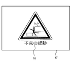
- an image see FIG. 5 showing that if the upper swivel body 3 suddenly starts turning, a surrounding person may be involved is applicable.
- the specific example of the precaution 18 displayed on the combiner 17 is not limited to this, and the seat belt should be worn, the open front window 7a may fall, and the hydraulic excavator 1 falls on a slope. It is possible to display various precautions such as the possibility of causing an electric shock when the front working machine 4 touches the electric wire.
- a decal 19 is attached to the inside of the cab 7.
- the decal 19 includes the same contents as the precautions 18 displayed on the combiner 17.
- the decal 19 according to the present embodiment is attached to the wall behind the sheet 10 and below the rear window 7d.
- the sticking position of the decal 19 is not limited to this, but it is desirable to stick the decal at a position that does not obstruct the operator's view (for example, a position other than the windows 7a to 7d).
- FIG. 3 is a block diagram of the hydraulic excavator 1.
- the hydraulic excavator 1 includes a controller 20 that controls the HUD unit. More specifically, the controller 20 controls the projection device 16 so that the display mode of the precaution 18 in the combiner 17 changes according to the states of the gate lock lever 13, the push button 14, and the key switch 15.
- the controller 20 includes a CPU (Central Processing Unit) 21, a ROM (Read Only Memory) 22, and a RAM (Random Access Memory) 23.
- the controller 20 realizes the processing described later by the CPU 21 reading and executing the program code stored in the ROM 22.
- the RAM 23 is used as a work area when the CPU 21 executes a program.
- controller 20 is not limited to this, and may be realized by hardware such as an ASIC (Application Specific Integrated Circuit) and an FPGA (Field-Programmable Gate Array).
- ASIC Application Specific Integrated Circuit
- FPGA Field-Programmable Gate Array
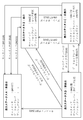
- FIG. 4 is a state transition diagram showing the relationship between the state of the hydraulic excavator 1 and the display status of the note 18.
- the controller 20 does not display the caution 18 on the combiner 17 (display status A). Further, when the key switch 15 is in the OFF state, even if the operator operates the gate lock lever 13 and the push button 14, the caution 18 remains hidden (the display mode does not change).
- the controller 20 gives a note 18 to the combiner 17. Is displayed (display status B).
- the controller 20 is displayed on the combiner 17 when the push button 14 is switched from the OFF state to the ON state (S12). Note 18 is hidden (display status C). Further, when the push button 14 is switched from the ON state to the OFF state when the key switch 15 is ON and the gate lock lever 13 is locked (S13), the controller 20 reminds the combiner 17 of the precaution 18 Is displayed (display status B).
- the controller 20 displays the precaution 18 while the push button 14 is not pressed, and the push button 14 is pressed. Note 18 is hidden while it is on. In other words, the controller 20 temporarily hides the note 18 only while the push button 14 is pressed. In other words, the controller 20 hides the caution 18 when the push button 14 is pressed even when the gate lock lever 13 is in the locked state.
- the controller 20 is displayed on the combiner 17 when the gate lock lever 13 is switched from the locked state to the unlocked state when the key switch 15 is in the ON state and the push button 14 is in the OFF state (S14).
- the notice 18 that had been used is hidden (display status D).
- the controller 20 when the gate lock lever 13 is switched from the unlocked state to the locked state when the key switch 15 is in the ON state and the push button 14 is in the OFF state (S15), the combiner 17 is noted. Is displayed (display status B).
- the controller 20 switches the gate lock lever 13 from the locked state to the unlocked state (S16) or from the locked state to the unlocked state. Even if it is (S17), the non-display of Note 18 is continued (display statuses C and D).
- the controller 20 continues to hide the caution 18 even if the state of the push button 14 is switched when the key switch 15 is in the ON state and the gate lock lever 13 is in the unlocked state (display status). C). That is, the operator can switch the display status of the precaution 18 by the push button 14 when the gate lock lever 13 is in the locked state, and cannot switch by the push button 14 when the gate lock lever 13 is in the unlocked state. ..
- the controller 20 is displayed on the combiner 17 when the key switch 15 is switched from the ON state to the OFF state when the gate lock lever 13 is in the locked state and the push button 14 is in the OFF state (S18). Note 18 is hidden (display status A).
- the controller 20 hides the caution 18 Continue (display status A).
- the controller 20 continues to hide the caution 18 (display status A).
- the caution 18 when the gate lock lever 13 is in the locked state, the caution 18 is displayed on the right side window 7c. As a result, the precaution 18 can be appropriately notified to the operator before starting the operation of the hydraulic excavator 1. Further, when the gate lock lever 13 is in the unlocked state, the caution 18 is hidden. As a result, the operator's view is not obstructed, so that the operator can safely operate the hydraulic excavator 1 while checking the surrounding conditions.
- the display / non-display of the caution 18 can be switched by the push button 14.
- the push button 14 the outside situation can be confirmed without obstructing the view.
- the push button 14 since the push button 14 is used as a momentary switch, the caution 18 remains hidden after the operator presses the push button 14 to check the outside situation. Can be prevented.
- the push button 14 may be an alternate switch that switches between an ON state and an OFF state each time the operator presses the button.
- the projection device 16 cannot display the caution 18 when the power is not supplied from the battery 8. Therefore, as in the above embodiment, by attaching the decal 19 having the same contents as the precaution 18 displayed on the combiner 17 to the cab 7, the operator is notified of the caution 18 even when the key switch 15 is in the OFF state. It can be notified. Further, by attaching the decal 19 to a place other than the windows 7a to 7d, the operator's view is not obstructed.
- FIG. 5 is a diagram showing an example in which the precautionary statement 18 is largely displayed in the center of the combiner 17.
- FIG. 6 is a diagram showing an example in which the precautionary statement 18 is displayed small on the end of the combiner 17.
- the controller 20 may display the caution 18 in a large size in the center of the combiner 17 when the display status is B. Further, as another example of the second display mode, as shown in FIG. 6, the controller 20 may display the precautions 18 small at the end of the combiner 17 when the display statuses are C and D.
- the second display mode either the precaution 18 is hidden, the display is smaller than the first display mode, or the notice 18 is displayed at the edge of the window from the display position in the first display mode. It may be one or a combination thereof.
- the second display mode has a higher transmittance than the first display mode, a lower saturation than the first display mode, and a higher brightness than the first display mode. To do, etc. That is, the second display mode may be a display mode that does not obstruct the operator's field of view as compared with the first display mode.
- the display mode of the precaution 18 in the display statuses C and D may be different.
- the controller 20 may display the precautions 18 as shown in FIG. 6 when the display status is C, and may hide the precautions 18 when the display status is D.
- the timing of switching from display status B to display status C and D may be different.
- the controller 20 may immediately switch the display mode of the precaution 18 when the push button 14 is switched from the OFF state to the ON state (S12).
- the controller 20 may switch the display mode of the caution 18 after a predetermined time (for example, 5 seconds) has elapsed. ..
- state detection unit is not limited to the gate lock lever 13, the push button 14, and the key switch 15.
- the tilt angle sensor that detects the tilt angle of the hydraulic excavator 1 with respect to the horizontal plane, or the front window sensor that detects that the front window 7a is open may be used as the state detection unit.
- the precautions 18 displayed on the combiner 17 at the same time are not limited to one. That is, the controller 20 may display a plurality of precautions 18 side by side on the combiner 17. Further, the controller 20 may switch the precautions 18 displayed on the combiner 17 according to the state of the hydraulic excavator 1 detected by the state detection unit.
- the controller 20 may display on the combiner 17 precautions for prompting the wearing of the seat belt immediately after the key switch 15 is switched from the OFF state to the ON state. Further, the controller 20 may display the precautions 18 shown in FIG. 5 on the combiner 17 after a predetermined time has elapsed after the key switch 15 is switched to the ON state.
- the controller 20 displays on the combiner 17 a caution to notify that the hydraulic excavator 1 may tip over on a slope when the tilt angle detected by the tilt angle sensor is equal to or greater than the threshold value. May be good. As yet another example, the controller 20 notifies that when the front window sensor detects that the front window 7a is open, the opened front window 7a may fall. May be displayed on the combiner 17.
- the controller 20 determines the amount of image light projected from the projection device 16 when the key switch 115 is in the battery-powered state, and when the key switch 15 is in the ON state. It may be smaller.
- the specific example of the work machine is not limited to the hydraulic excavator 1, and may be a work vehicle such as a dump truck, a motor grader, or a wheel loader, or a fixed machine that operates by being fixed to a post. Good.
Landscapes
- Engineering & Computer Science (AREA)
- Chemical & Material Sciences (AREA)
- Combustion & Propulsion (AREA)
- Transportation (AREA)
- Mechanical Engineering (AREA)
- Mining & Mineral Resources (AREA)
- Civil Engineering (AREA)
- General Engineering & Computer Science (AREA)
- Structural Engineering (AREA)
- Component Parts Of Construction Machinery (AREA)
Abstract
Description
2 下部走行体
3 上部旋回体
4 フロント作業機
4a ブーム
4b アーム
4c バケット
4d,4e,4f 油圧シリンダ
5 旋回フレーム
6 カウンタウェイト
7 キャブ
7a 前面窓
7b 左面窓
7c 右面窓
7d 背面窓
8 バッテリー
9 無限軌道
10 シート
11 走行操作レバー
12 フロント操作レバー
13 ゲートロックレバー(ロック操作部)
14 プッシュボタン
15 キースイッチ
16 投射装置
17 コンバイナ
18 注意事項
19 デカール
20 コントローラ
21 CPU
22 ROM
23 RAM
Claims (4)
- オペレータが搭乗するキャブを備える作業機械であって、
前記作業機械を操作するオペレータへの注意事項を示す画像光を投射する投射装置と、
前記投射装置によって投射される画像光を表示する表示部と、
前記作業機械の状態を検出する状態検出部と、
前記状態検出部で検出した前記作業機械の状態に応じて、前記表示部における前記注意事項の表示態様が変化するように、前記投射装置を制御するコントローラとを備えることを特徴とする作業機械。 - 請求項1に記載の作業機械において、
前記作業機械の動作を規制するロック状態、及び前記作業機械の動作を許容する非ロック状態に、オペレータが切り換え可能なロック操作部を備え、
前記コントローラは、前記表示部に表示する前記注意事項を、前記ロック操作部が前記非ロック状態のときには、前記ロック操作部が前記ロック状態のときに表示する第1の表示態様よりもオペレータの視界を妨げない第2の表示態様にすることを特徴とする作業機械。 - 請求項2に記載の作業機械において、
オペレータによって操作されている間だけON状態となり、オペレータが操作をやめるとOFF状態になるモーメンタリスイッチを備え、
前記コントローラは、前記ロック操作部が前記ロック状態であっても前記モーメンタリスイッチがON状態の場合には、前記表示部に表示する前記注意事項を前記第2の表示態様にすることを特徴とする作業機械。 - 請求項2に記載の作業機械において、
前記第2の表示態様は、非表示にすること、前記第1の表示態様より小さく表示すること、前記第1の表示態様における表示位置より窓の端に表示すること、のいずれかであることを特徴とする作業機械。
Priority Applications (4)
| Application Number | Priority Date | Filing Date | Title |
|---|---|---|---|
| CN201980055494.4A CN112639216B (zh) | 2019-03-08 | 2019-12-11 | 作业机械 |
| US17/272,692 US11952750B2 (en) | 2019-03-08 | 2019-12-11 | Work machine |
| EP19918800.4A EP3936671B1 (en) | 2019-03-08 | 2019-12-11 | Work machine |
| KR1020217004726A KR102494287B1 (ko) | 2019-03-08 | 2019-12-11 | 작업 기계 |
Applications Claiming Priority (2)
| Application Number | Priority Date | Filing Date | Title |
|---|---|---|---|
| JP2019042923A JP7012038B2 (ja) | 2019-03-08 | 2019-03-08 | 作業機械 |
| JP2019-042923 | 2019-03-08 |
Publications (1)
| Publication Number | Publication Date |
|---|---|
| WO2020183829A1 true WO2020183829A1 (ja) | 2020-09-17 |
Family
ID=72355470
Family Applications (1)
| Application Number | Title | Priority Date | Filing Date |
|---|---|---|---|
| PCT/JP2019/048445 Ceased WO2020183829A1 (ja) | 2019-03-08 | 2019-12-11 | 作業機械 |
Country Status (6)
| Country | Link |
|---|---|
| US (1) | US11952750B2 (ja) |
| EP (1) | EP3936671B1 (ja) |
| JP (1) | JP7012038B2 (ja) |
| KR (1) | KR102494287B1 (ja) |
| CN (1) | CN112639216B (ja) |
| WO (1) | WO2020183829A1 (ja) |
Families Citing this family (2)
| Publication number | Priority date | Publication date | Assignee | Title |
|---|---|---|---|---|
| JP7510895B2 (ja) * | 2021-02-16 | 2024-07-04 | 株式会社小松製作所 | 作業機械の表示システム |
| WO2023122742A1 (en) * | 2021-12-22 | 2023-06-29 | Clark Equipment Company | Control of multiple power machines |
Citations (4)
| Publication number | Priority date | Publication date | Assignee | Title |
|---|---|---|---|---|
| JP2009173195A (ja) * | 2008-01-25 | 2009-08-06 | Sumitomo (Shi) Construction Machinery Manufacturing Co Ltd | 建設機械用表示システム |
| WO2017043107A1 (ja) * | 2015-09-10 | 2017-03-16 | 富士フイルム株式会社 | 投写型表示装置及び投写制御方法 |
| WO2017051655A1 (ja) * | 2015-09-25 | 2017-03-30 | 富士フイルム株式会社 | 投写型表示装置及び投写制御方法 |
| WO2018116601A1 (ja) * | 2016-12-21 | 2018-06-28 | 富士フイルム株式会社 | 投写型表示装置、投写型表示装置の制御方法、投写型表示装置の制御プログラム |
Family Cites Families (12)
| Publication number | Priority date | Publication date | Assignee | Title |
|---|---|---|---|---|
| JP4010255B2 (ja) * | 2003-02-07 | 2007-11-21 | コベルコ建機株式会社 | 建設機械の制御装置 |
| KR100702180B1 (ko) * | 2005-08-11 | 2007-04-02 | 볼보 컨스트럭션 이키프먼트 홀딩 스웨덴 에이비 | 건설기계용 운전자 진동 모니터링 장치 |
| WO2012015078A1 (ko) | 2010-07-28 | 2012-02-02 | 볼보 컨스트럭션 이큅먼트 에이비 | 건설기계용 운전실 리어 유리 고정장치 |
| JP5841008B2 (ja) * | 2012-05-28 | 2016-01-06 | ヤンマー株式会社 | 旋回作業車 |
| CN102852170A (zh) * | 2012-08-27 | 2013-01-02 | 泰州市华骏机械设备制造有限公司 | 一种具有辅助视像系统的挖掘机 |
| JP6102628B2 (ja) * | 2013-08-09 | 2017-03-29 | アイシン・エィ・ダブリュ株式会社 | ヘッドアップディスプレイ装置 |
| JP6308923B2 (ja) * | 2014-09-18 | 2018-04-11 | 住友建機株式会社 | 建設機械 |
| JP6361986B2 (ja) * | 2016-05-30 | 2018-07-25 | マツダ株式会社 | 車両用表示装置 |
| JP6808377B2 (ja) * | 2016-06-27 | 2021-01-06 | 住友建機株式会社 | ショベルの表示装置 |
| KR101899981B1 (ko) * | 2016-12-02 | 2018-09-19 | 엘지전자 주식회사 | 차량용 헤드 업 디스플레이 |
| JP6630855B2 (ja) | 2017-01-10 | 2020-01-15 | 富士フイルム株式会社 | 投写型表示装置、投写型表示装置の制御方法、投写型表示装置の制御プログラム |
| JP7039983B2 (ja) * | 2017-12-13 | 2022-03-23 | コベルコ建機株式会社 | 建設機械用の注意喚起装置 |
-
2019
- 2019-03-08 JP JP2019042923A patent/JP7012038B2/ja active Active
- 2019-12-11 WO PCT/JP2019/048445 patent/WO2020183829A1/ja not_active Ceased
- 2019-12-11 EP EP19918800.4A patent/EP3936671B1/en active Active
- 2019-12-11 KR KR1020217004726A patent/KR102494287B1/ko active Active
- 2019-12-11 US US17/272,692 patent/US11952750B2/en active Active
- 2019-12-11 CN CN201980055494.4A patent/CN112639216B/zh active Active
Patent Citations (4)
| Publication number | Priority date | Publication date | Assignee | Title |
|---|---|---|---|---|
| JP2009173195A (ja) * | 2008-01-25 | 2009-08-06 | Sumitomo (Shi) Construction Machinery Manufacturing Co Ltd | 建設機械用表示システム |
| WO2017043107A1 (ja) * | 2015-09-10 | 2017-03-16 | 富士フイルム株式会社 | 投写型表示装置及び投写制御方法 |
| WO2017051655A1 (ja) * | 2015-09-25 | 2017-03-30 | 富士フイルム株式会社 | 投写型表示装置及び投写制御方法 |
| WO2018116601A1 (ja) * | 2016-12-21 | 2018-06-28 | 富士フイルム株式会社 | 投写型表示装置、投写型表示装置の制御方法、投写型表示装置の制御プログラム |
Non-Patent Citations (1)
| Title |
|---|
| See also references of EP3936671A4 |
Also Published As
| Publication number | Publication date |
|---|---|
| KR102494287B1 (ko) | 2023-02-06 |
| US11952750B2 (en) | 2024-04-09 |
| JP7012038B2 (ja) | 2022-01-27 |
| JP2020143559A (ja) | 2020-09-10 |
| US20210340732A1 (en) | 2021-11-04 |
| EP3936671A1 (en) | 2022-01-12 |
| EP3936671A4 (en) | 2022-12-07 |
| KR20210031743A (ko) | 2021-03-22 |
| CN112639216A (zh) | 2021-04-09 |
| CN112639216B (zh) | 2022-12-16 |
| EP3936671B1 (en) | 2026-02-11 |
Similar Documents
| Publication | Publication Date | Title |
|---|---|---|
| JP7407178B2 (ja) | ショベル | |
| CN113727883B (zh) | 显示装置、挖土机、信息处理装置 | |
| JP7358070B2 (ja) | ショベル | |
| CN109070800A (zh) | 用于车辆的图像显示设备和方法 | |
| KR101435659B1 (ko) | 사각지대 모니터링 장치 | |
| JP6886106B2 (ja) | 電子ミラーシステム、自動車用ドア及び自動車 | |
| JP6446595B2 (ja) | 投写型表示装置、投写表示方法、及び、投写表示プログラム | |
| JP7012038B2 (ja) | 作業機械 | |
| JP2011189775A (ja) | 車両の後側方確認装置 | |
| JP2023104605A (ja) | 車両用表示システム及び車両用表示方法 | |
| JP4567914B2 (ja) | 建設機械 | |
| US20180363273A1 (en) | Work vehicle | |
| JP5986042B2 (ja) | 建設機械の走行警報装置 | |
| JP6547077B2 (ja) | 投写型表示装置、投写型表示装置の制御方法、投写型表示装置の制御プログラム | |
| JP2005088759A (ja) | 幅寄せカメラ | |
| JP6922730B2 (ja) | 建設機械の表示システム | |
| JP2870245B2 (ja) | 車両用表示装置 | |
| WO2019021587A1 (ja) | 投写型表示装置、投写型表示装置の制御方法、投写型表示装置の制御プログラム | |
| KR100645986B1 (ko) | 방향전환시 육안관찰이 불가능한 측면의 영상정보를운전자에게 제공하는 차량 및 이를 이용한 차량 방향전환제어방법 | |
| JP2020160092A (ja) | 投写型表示装置、投写型表示装置の制御方法、投写型表示装置の制御プログラム | |
| JP2004243889A (ja) | ヘッドアップディスプレイ | |
| JP2020157779A (ja) | 投写型表示装置、投写型表示装置の制御方法、投写型表示装置の制御プログラム | |
| JPH07266927A (ja) | 車両の表示装置 | |
| JP2021142931A (ja) | 画像投射装置 | |
| KR20060034084A (ko) | 차량 주행 전방 안전 주시 카메라장치 |
Legal Events
| Date | Code | Title | Description |
|---|---|---|---|
| 121 | Ep: the epo has been informed by wipo that ep was designated in this application |
Ref document number: 19918800 Country of ref document: EP Kind code of ref document: A1 |
|
| ENP | Entry into the national phase |
Ref document number: 20217004726 Country of ref document: KR Kind code of ref document: A |
|
| NENP | Non-entry into the national phase |
Ref country code: DE |
|
| WWE | Wipo information: entry into national phase |
Ref document number: 2019918800 Country of ref document: EP |
|
| WWG | Wipo information: grant in national office |
Ref document number: 2019918800 Country of ref document: EP |