WO2020184013A1 - Dispositif de commande de véhicule - Google Patents
Dispositif de commande de véhicule Download PDFInfo
- Publication number
- WO2020184013A1 WO2020184013A1 PCT/JP2020/004723 JP2020004723W WO2020184013A1 WO 2020184013 A1 WO2020184013 A1 WO 2020184013A1 JP 2020004723 W JP2020004723 W JP 2020004723W WO 2020184013 A1 WO2020184013 A1 WO 2020184013A1
- Authority
- WO
- WIPO (PCT)
- Prior art keywords
- vehicle
- reliability
- lane
- detection unit
- unit
- Prior art date
- Legal status (The legal status is an assumption and is not a legal conclusion. Google has not performed a legal analysis and makes no representation as to the accuracy of the status listed.)
- Ceased
Links
Images

Classifications
-
- G—PHYSICS
- G01—MEASURING; TESTING
- G01C—MEASURING DISTANCES, LEVELS OR BEARINGS; SURVEYING; NAVIGATION; GYROSCOPIC INSTRUMENTS; PHOTOGRAMMETRY OR VIDEOGRAMMETRY
- G01C21/00—Navigation; Navigational instruments not provided for in groups G01C1/00 - G01C19/00
- G01C21/26—Navigation; Navigational instruments not provided for in groups G01C1/00 - G01C19/00 specially adapted for navigation in a road network
- G01C21/28—Navigation; Navigational instruments not provided for in groups G01C1/00 - G01C19/00 specially adapted for navigation in a road network with correlation of data from several navigational instruments
- G01C21/30—Map- or contour-matching
- G01C21/32—Structuring or formatting of map data
-
- B—PERFORMING OPERATIONS; TRANSPORTING
- B60—VEHICLES IN GENERAL
- B60W—CONJOINT CONTROL OF VEHICLE SUB-UNITS OF DIFFERENT TYPE OR DIFFERENT FUNCTION; CONTROL SYSTEMS SPECIALLY ADAPTED FOR HYBRID VEHICLES; ROAD VEHICLE DRIVE CONTROL SYSTEMS FOR PURPOSES NOT RELATED TO THE CONTROL OF A PARTICULAR SUB-UNIT
- B60W30/00—Purposes of road vehicle drive control systems not related to the control of a particular sub-unit, e.g. of systems using conjoint control of vehicle sub-units
- B60W30/10—Path keeping
- B60W30/12—Lane keeping
-
- B—PERFORMING OPERATIONS; TRANSPORTING
- B60—VEHICLES IN GENERAL
- B60W—CONJOINT CONTROL OF VEHICLE SUB-UNITS OF DIFFERENT TYPE OR DIFFERENT FUNCTION; CONTROL SYSTEMS SPECIALLY ADAPTED FOR HYBRID VEHICLES; ROAD VEHICLE DRIVE CONTROL SYSTEMS FOR PURPOSES NOT RELATED TO THE CONTROL OF A PARTICULAR SUB-UNIT
- B60W40/00—Estimation or calculation of non-directly measurable driving parameters for road vehicle drive control systems not related to the control of a particular sub unit, e.g. by using mathematical models
- B60W40/02—Estimation or calculation of non-directly measurable driving parameters for road vehicle drive control systems not related to the control of a particular sub unit, e.g. by using mathematical models related to ambient conditions
-
- B—PERFORMING OPERATIONS; TRANSPORTING
- B60—VEHICLES IN GENERAL
- B60W—CONJOINT CONTROL OF VEHICLE SUB-UNITS OF DIFFERENT TYPE OR DIFFERENT FUNCTION; CONTROL SYSTEMS SPECIALLY ADAPTED FOR HYBRID VEHICLES; ROAD VEHICLE DRIVE CONTROL SYSTEMS FOR PURPOSES NOT RELATED TO THE CONTROL OF A PARTICULAR SUB-UNIT
- B60W40/00—Estimation or calculation of non-directly measurable driving parameters for road vehicle drive control systems not related to the control of a particular sub unit, e.g. by using mathematical models
- B60W40/02—Estimation or calculation of non-directly measurable driving parameters for road vehicle drive control systems not related to the control of a particular sub unit, e.g. by using mathematical models related to ambient conditions
- B60W40/06—Road conditions
-
- G—PHYSICS
- G01—MEASURING; TESTING
- G01C—MEASURING DISTANCES, LEVELS OR BEARINGS; SURVEYING; NAVIGATION; GYROSCOPIC INSTRUMENTS; PHOTOGRAMMETRY OR VIDEOGRAMMETRY
- G01C21/00—Navigation; Navigational instruments not provided for in groups G01C1/00 - G01C19/00
- G01C21/26—Navigation; Navigational instruments not provided for in groups G01C1/00 - G01C19/00 specially adapted for navigation in a road network
- G01C21/34—Route searching; Route guidance
- G01C21/36—Input/output arrangements for on-board computers
- G01C21/3602—Input other than that of destination using image analysis, e.g. detection of road signs, lanes, buildings, real preceding vehicles using a camera
-
- G—PHYSICS
- G01—MEASURING; TESTING
- G01C—MEASURING DISTANCES, LEVELS OR BEARINGS; SURVEYING; NAVIGATION; GYROSCOPIC INSTRUMENTS; PHOTOGRAMMETRY OR VIDEOGRAMMETRY
- G01C21/00—Navigation; Navigational instruments not provided for in groups G01C1/00 - G01C19/00
- G01C21/26—Navigation; Navigational instruments not provided for in groups G01C1/00 - G01C19/00 specially adapted for navigation in a road network
- G01C21/34—Route searching; Route guidance
- G01C21/36—Input/output arrangements for on-board computers
- G01C21/3626—Details of the output of route guidance instructions
- G01C21/3658—Lane guidance
-
- G—PHYSICS
- G01—MEASURING; TESTING
- G01S—RADIO DIRECTION-FINDING; RADIO NAVIGATION; DETERMINING DISTANCE OR VELOCITY BY USE OF RADIO WAVES; LOCATING OR PRESENCE-DETECTING BY USE OF THE REFLECTION OR RERADIATION OF RADIO WAVES; ANALOGOUS ARRANGEMENTS USING OTHER WAVES
- G01S19/00—Satellite radio beacon positioning systems; Determining position, velocity or attitude using signals transmitted by such systems
- G01S19/38—Determining a navigation solution using signals transmitted by a satellite radio beacon positioning system
- G01S19/39—Determining a navigation solution using signals transmitted by a satellite radio beacon positioning system the satellite radio beacon positioning system transmitting time-stamped messages, e.g. GPS [Global Positioning System], GLONASS [Global Orbiting Navigation Satellite System] or GALILEO
- G01S19/396—Determining accuracy or reliability of position or pseudorange measurements
-
- G—PHYSICS
- G01—MEASURING; TESTING
- G01S—RADIO DIRECTION-FINDING; RADIO NAVIGATION; DETERMINING DISTANCE OR VELOCITY BY USE OF RADIO WAVES; LOCATING OR PRESENCE-DETECTING BY USE OF THE REFLECTION OR RERADIATION OF RADIO WAVES; ANALOGOUS ARRANGEMENTS USING OTHER WAVES
- G01S19/00—Satellite radio beacon positioning systems; Determining position, velocity or attitude using signals transmitted by such systems
- G01S19/38—Determining a navigation solution using signals transmitted by a satellite radio beacon positioning system
- G01S19/39—Determining a navigation solution using signals transmitted by a satellite radio beacon positioning system the satellite radio beacon positioning system transmitting time-stamped messages, e.g. GPS [Global Positioning System], GLONASS [Global Orbiting Navigation Satellite System] or GALILEO
- G01S19/42—Determining position
- G01S19/48—Determining position by combining or switching between position solutions derived from the satellite radio beacon positioning system and position solutions derived from a further system
- G01S19/485—Determining position by combining or switching between position solutions derived from the satellite radio beacon positioning system and position solutions derived from a further system whereby the further system is an optical system or imaging system
-
- G—PHYSICS
- G06—COMPUTING OR CALCULATING; COUNTING
- G06V—IMAGE OR VIDEO RECOGNITION OR UNDERSTANDING
- G06V20/00—Scenes; Scene-specific elements
- G06V20/50—Context or environment of the image
- G06V20/56—Context or environment of the image exterior to a vehicle by using sensors mounted on the vehicle
- G06V20/588—Recognition of the road, e.g. of lane markings; Recognition of the vehicle driving pattern in relation to the road
-
- B—PERFORMING OPERATIONS; TRANSPORTING
- B60—VEHICLES IN GENERAL
- B60W—CONJOINT CONTROL OF VEHICLE SUB-UNITS OF DIFFERENT TYPE OR DIFFERENT FUNCTION; CONTROL SYSTEMS SPECIALLY ADAPTED FOR HYBRID VEHICLES; ROAD VEHICLE DRIVE CONTROL SYSTEMS FOR PURPOSES NOT RELATED TO THE CONTROL OF A PARTICULAR SUB-UNIT
- B60W2420/00—Indexing codes relating to the type of sensors based on the principle of their operation
- B60W2420/40—Photo, light or radio wave sensitive means, e.g. infrared sensors
- B60W2420/403—Image sensing, e.g. optical camera
-
- B—PERFORMING OPERATIONS; TRANSPORTING
- B60—VEHICLES IN GENERAL
- B60W—CONJOINT CONTROL OF VEHICLE SUB-UNITS OF DIFFERENT TYPE OR DIFFERENT FUNCTION; CONTROL SYSTEMS SPECIALLY ADAPTED FOR HYBRID VEHICLES; ROAD VEHICLE DRIVE CONTROL SYSTEMS FOR PURPOSES NOT RELATED TO THE CONTROL OF A PARTICULAR SUB-UNIT
- B60W2552/00—Input parameters relating to infrastructure
- B60W2552/10—Number of lanes
-
- B—PERFORMING OPERATIONS; TRANSPORTING
- B60—VEHICLES IN GENERAL
- B60W—CONJOINT CONTROL OF VEHICLE SUB-UNITS OF DIFFERENT TYPE OR DIFFERENT FUNCTION; CONTROL SYSTEMS SPECIALLY ADAPTED FOR HYBRID VEHICLES; ROAD VEHICLE DRIVE CONTROL SYSTEMS FOR PURPOSES NOT RELATED TO THE CONTROL OF A PARTICULAR SUB-UNIT
- B60W2552/00—Input parameters relating to infrastructure
- B60W2552/53—Road markings, e.g. lane marker or crosswalk
-
- B—PERFORMING OPERATIONS; TRANSPORTING
- B60—VEHICLES IN GENERAL
- B60W—CONJOINT CONTROL OF VEHICLE SUB-UNITS OF DIFFERENT TYPE OR DIFFERENT FUNCTION; CONTROL SYSTEMS SPECIALLY ADAPTED FOR HYBRID VEHICLES; ROAD VEHICLE DRIVE CONTROL SYSTEMS FOR PURPOSES NOT RELATED TO THE CONTROL OF A PARTICULAR SUB-UNIT
- B60W2556/00—Input parameters relating to data
- B60W2556/40—High definition maps
-
- B—PERFORMING OPERATIONS; TRANSPORTING
- B60—VEHICLES IN GENERAL
- B60W—CONJOINT CONTROL OF VEHICLE SUB-UNITS OF DIFFERENT TYPE OR DIFFERENT FUNCTION; CONTROL SYSTEMS SPECIALLY ADAPTED FOR HYBRID VEHICLES; ROAD VEHICLE DRIVE CONTROL SYSTEMS FOR PURPOSES NOT RELATED TO THE CONTROL OF A PARTICULAR SUB-UNIT
- B60W2556/00—Input parameters relating to data
- B60W2556/45—External transmission of data to or from the vehicle
-
- B—PERFORMING OPERATIONS; TRANSPORTING
- B60—VEHICLES IN GENERAL
- B60W—CONJOINT CONTROL OF VEHICLE SUB-UNITS OF DIFFERENT TYPE OR DIFFERENT FUNCTION; CONTROL SYSTEMS SPECIALLY ADAPTED FOR HYBRID VEHICLES; ROAD VEHICLE DRIVE CONTROL SYSTEMS FOR PURPOSES NOT RELATED TO THE CONTROL OF A PARTICULAR SUB-UNIT
- B60W2556/00—Input parameters relating to data
- B60W2556/45—External transmission of data to or from the vehicle
- B60W2556/50—External transmission of data to or from the vehicle of positioning data, e.g. GPS [Global Positioning System] data
Definitions
- the present invention relates to a vehicle control device that controls the operation of a vehicle.
- the position of the vehicle is generally obtained by combining the absolute position, orientation, and vehicle speed of the vehicle estimated by, for example, GNSS (Global Navigation Satellite System) with the relative movement amount of the vehicle estimated by the vehicle speed sensor or the gyro sensor. It can be estimated with high accuracy.
- GNSS Global Navigation Satellite System
- the vehicle control device assists the driver in driving the vehicle, it may be useful to estimate which lane the vehicle is traveling on the road in addition to the position of the vehicle. For example, in a scene where a vehicle is traveling on an expressway, by estimating the lane (driving lane) in which the vehicle is traveling, it is possible to distinguish whether the vehicle is traveling on the main line or the branch road of the expressway, and to distinguish the road type. It is conceivable to provide driving support suitable for.
- Patent Document 1 discloses a technique for estimating a traveling lane.
- the document states, "To accurately estimate whether or not your vehicle has entered a branch road that branches off from the main line of the driving road. ”,“ The number of lanes on the road on which the vehicle is traveling is detected (S110), the number of lanes and the driving lane of the vehicle are estimated from the detection result of the delineator (S120), and the lane is detected from the detection result of the vehicle in front. Estimate the number and the driving lane of the own vehicle (S130).
- the traveling lane of the own vehicle Is estimated (S140). Therefore, it is possible to increase the reliability of the estimation result of the traveling lane, and it is possible to accurately estimate whether or not the own vehicle has entered the branch road branched from the main line of the traveling road based on the estimation result. ⁇ Disclosures the technology (see summary).
- the conventional driving lane estimation it is common to estimate the driving lane using a single detection method.
- a single detection method for example, in an environment where the accuracy of the sensor used in the detection method is lowered, the reliability of the estimation result itself is lowered.
- the present invention has been made in view of the above problems, and even when the accuracy of any of the detection methods is not sufficient when determining a traveling lane using a plurality of detection methods. It is an object of the present invention to provide a technique capable of accurately estimating a traveling lane.
- the vehicle control device calculates the integrated reliability by integrating the reliability of the traveling lane estimation result by the first detection unit and the traveling lane estimation result by the second detection unit, and mutually agrees the integrated reliability.
- the driving lane is estimated by comparing with.
- the accuracy of the estimation result by any of the detection units is not sufficient by integrating and comparing the reliability of the estimation result by each detection unit.
- the driving lane can be estimated accurately.
- the vehicle control device since the estimation results by each detection unit are mutually compared by a unified scale of reliability, it is possible to easily add or delete detection units. ..
- FIG. It is a block diagram of the vehicle control device 100 which concerns on Embodiment 1.
- FIG. It is a detailed block diagram of the traveling lane estimation unit 113. It is a figure explaining the procedure which the integrated reliability calculation unit 1137 calculates the integrated reliability. It is a figure explaining the reliability of the estimation result by the 1st detection unit 1131. It is a figure explaining the reliability of the estimation result by the 2nd detection unit 1132. It is a figure explaining the reliability of the estimation result by the 3rd detection unit 1133.
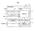
- FIG. 1 is a configuration diagram of a vehicle control device 100 according to a first embodiment of the present invention.
- the vehicle control device 100 is a device that controls the operation of the vehicle and is mounted in the vehicle.
- the vehicle control device 100 includes a calculation unit 110, a GNSS tuner 120, a gyro sensor 130, and a high-precision map 140.
- the calculation unit 110 includes a position estimation unit 111, a traveling lane estimation unit 113, and a position correction unit 114.
- the GNSS tuner 120 acquires the absolute position, bearing, and moving speed of the vehicle from the GNSS.
- the gyro sensor 130 measures the angular velocity of each rotation axis of the vehicle and estimates the posture of the vehicle.
- As the rotation axis generally, only the yaw axis or three axes including the pitch axis and the roll axis are measured.
- the high-precision map 140 is stored in advance in a storage device included in the vehicle control device 100. For example, the coordinates of the road center line and the lane markings constituting the traveling lane can be stored as a high-precision map 140.
- the position estimation unit 111 estimates the position of the vehicle by using information such as the absolute position, azimuth, and moving speed acquired by the GNSS tuner 120, the angular velocity acquired by the gyro sensor 130, and the vehicle speed of the vehicle.
- the traveling lane estimation unit 113 estimates the road and traveling lane on which the vehicle is traveling by comparing the position of the vehicle with the high-precision map 140. Details will be described later.
- the position correction unit 114 acquires a peripheral image of the vehicle from a photographing device such as a camera, and corrects the position of the vehicle based on the peripheral image.
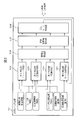
- FIG. 2 is a detailed configuration diagram of the traveling lane estimation unit 113.
- the traveling lane estimation unit 113 includes a plurality of detection units for estimating the traveling lane.
- an example including the first detection unit 1131 to the fourth detection unit 1134 is shown.
- Each detection unit estimates the traveling lane by different detection means and estimation methods. The specific estimation method by each detection unit will be described later.
- the traveling lane estimation unit 113 further includes a reliability calculation unit 1136, an integrated reliability calculation unit 1137, and a traveling lane determination unit 1138.
- the reliability calculation unit 1136 calculates the reliability of the estimation result by each detection unit. Instead of this, each detection unit may calculate the reliability by itself. In the following, for convenience of explanation, the reliability calculation unit 1136 will calculate the reliability.
- the integrated reliability calculation unit 1137 calculates the integrated reliability by integrating the reliability for each lane. A specific example of calculating the integrated reliability will be described later.
- the travel lane determination unit 1138 finally estimates the travel lane by comparing the integrated reliability with each other.
- the estimation result is output as, for example, the lane number and its reliability.
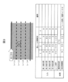
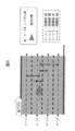
- FIG. 3 is a diagram illustrating a procedure in which the integrated reliability calculation unit 1137 calculates the integrated reliability.
- the estimation result of the traveling lane output by each detection unit is not necessarily limited to one, and a plurality of candidates for the traveling lane may be output as the estimation result.
- the reliability calculation unit 1136 calculates the reliability for each candidate. In the example shown in FIG. 3, it is assumed that the reliability of the estimation result of each detection unit is obtained as shown in the table in the figure.
- the integrated reliability calculation unit 1137 integrates the reliability of the estimation result by each detection unit for each lane.
- the second detection unit 1132 and the third detection unit 1133 output lane number 3 as a candidate for a traveling lane, respectively, and their reliabilitys are 80 and 40, respectively.
- Other detection units do not use lane number 3 as a candidate for a traveling lane. Therefore, the total reliability for lane number 3 is 120.
- the reliability is integrated for each lane.
- the reliability is simply added up to integrate, but for example, each detection unit can be weighted. For example, when the estimation result by the first detection unit 1131 is emphasized, the weight related to the first detection unit 1131 may be larger than the weight related to the other detection units.
- the integrated reliability calculation unit 1137 further calculates the integrated reliability of each lane by obtaining the relative ratio of the integrated reliability for each lane.
- the integrated reliability is calculated for other lane numbers in the same way.
- the integrated reliability is the integration of the estimation results by each detection unit across lanes. Therefore, even if the reliability of the estimation result by one of the detection units is low, if the reliability of the estimation result by the other detection unit is high, the accuracy of the integrated reliability is considered to be sufficiently high.
- the traveling lane is estimated by comparing the integrated reliability with each other. Therefore, the traveling lane determination unit 1138 outputs the lane number having the highest integrated reliability and the integrated reliability as an estimation result.
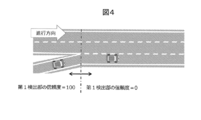
- FIG. 4 is a diagram for explaining the reliability of the estimation result by the first detection unit 1131.
- the first detection unit 1131 determines whether or not the vehicle is traveling on a road having only one lane (one-lane road) by inquiring the high-precision map 140 according to the vehicle position estimated by the position estimation unit 111. To do. For example, it is possible to acquire the number of lanes on a road and determine whether or not the vehicle is traveling on a one-lane road based on whether or not the number of lanes is 1.
- the reliability calculation unit 1136 increases the reliability in the section where the first detection unit 1131 determines that the vehicle is traveling on the one-lane road, as compared with the other sections. For example, the following example can be considered.
- the reliability of the estimation result by the first detection unit 1131 is set higher in the former when comparing the section determined by the first detection unit 1131 that the vehicle is traveling on the one-lane road and the other sections. To. For example, as shown in FIG. 4, the reliability of the first detection unit 1131 is 100 in the section where the vehicle is traveling on the one-lane road, and the reliability of the first detection unit 1131 is 0 in the other sections. ..
- Example of reliability of 1-lane road Part 2
- the reliability of the estimation result by the first detection unit 1131 is set higher than the reliability of the determination result by the other detection units. Will be done.
- the reliability of the first detection unit 1131 in a section in which the vehicle is traveling on a one-lane road is 100, and the reliability of the other detection units is less than 100 even if the detection unit is sufficiently reliable. Is set to. In the other sections, the reliability of each detection unit is treated equally.
- the traveling lane determination unit 1138 travels on the one-lane road regardless of the estimation results of the other detection units. It is considered to be. This is because if the accuracy of the vehicle position is sufficiently high, it is of little significance to estimate the traveling lane on a road having only one lane.
- the estimation result of the first detection unit 1131 may be adopted by setting the reliability of the first detection unit 1131 to be extremely high, or the integrated reliability calculation unit 1137 may be skipped.
- the traveling lane determination unit 1138 may finally determine the traveling lane.
- FIG. 5 is a diagram for explaining the reliability of the estimation result by the second detection unit 1132.
- the second detection unit 1132 acquires the number of lanes and the lane marking type information of the road currently traveling by inquiring the high-precision map 140 according to the vehicle position estimated by the position estimation unit 111.
- the second detection unit 1132 further estimates the lane in which the vehicle is traveling by identifying the road lane marking type included in the peripheral image of the vehicle.
- the second detection unit 1132 Based on the result of inquiring the high-precision map 140, the second detection unit 1132 further determines that on the road on which the vehicle is traveling, only lane 1 has a solid line on the left side and a dotted line on the right side. Can be judged. Therefore, the second detection unit 1132 estimates that the vehicle is traveling in lane 1.
- the reliability calculation unit 1136 sets the reliability of the traveling lane estimated by the second detection unit 1132 based on the lane marking type to be higher than that of the other lanes.
- the second detection unit 1132 determined that the vehicle was traveling in lane 1 based on the section line type. Therefore, the reliability of lane 1 is set higher than the reliability of other lanes.
- the second detection unit 1132 is traveling in lane 2 or lane 3.
- the reliability may be set lower than when the traveling lane 1 or 4 is estimated as the traveling lane.
- FIG. 6 is a diagram for explaining the reliability of the estimation result by the third detection unit 1133.
- the third detection unit 1133 estimates the road on which the vehicle is traveling by inquiring the high-precision map 140 according to the vehicle position estimated by the position estimation unit 111.
- the third detection unit 1133 further obtains the coordinates of the center lines of all the lanes of the road by inquiring the high-precision map 140.
- the reliability calculation unit 1136 calculates the distance (perpendicular distance) between the estimated vehicle position and the center line of each lane.
- the reliability calculation unit 1136 sets the reliability higher in the lane where the distance between the vehicle position and the center line is shorter. For example, the following example can be considered.
- (A) The reliability of the lane with the shortest distance to the center line is set to the highest, and the reliability of the other lanes is set to a uniform value lower than that.
- B Set the reliability so that it is inversely proportional to the distance to the center line.
- C The reliability is set to 0 for lanes other than the lane with the shortest distance to the center line.
- the fourth detection unit 1134 periodically acquires the measurement distance from the vehicle to the lane marking obtained from the peripheral image of the vehicle, and based on the measurement distance, whether or not the vehicle has moved between lanes across the lane marking. Is determined for each cycle.
- the fourth detection unit 1134 considers that the traveling lane has not been changed until it is determined that the vehicle has moved between the lanes across the lane markings.
- the estimation result of the traveling lane determination unit 1138 can be used. Alternatively, the estimation result by another determination unit may be used.
- the vehicle control device 100 calculates the integrated reliability by integrating the reliability of the estimation result by each detection unit for each lane, and finalizes the traveling lane by comparing the integrated reliability with each other. Estimate. As a result, even if the reliability of the detection method (detector such as camera or GNSS tuner, and estimation method) used by one of the detection units is low, the reliability of the detection method used by the other detection unit is integrated. By doing so, it is possible to obtain an accurate estimation result by compensating for the low reliability.
- the detection method detector such as camera or GNSS tuner, and estimation method
- the traveling lane estimation using the position estimation result (first detection unit 1131 to the third detection unit 1133) and the traveling lane estimation using the vehicle peripheral image (fourth detection unit 1134).
- the detection method used by each detection unit to estimate the travel lane such as the travel lane estimation (second detection unit 1132) using these in combination, differs for each detection unit. Therefore, the integrated reliability is calculated by integrating the results of estimating the traveling lanes from a plurality of viewpoints. As a result, the reliability of the final estimation result can be increased.
- the estimation result is prioritized over the other detection units.
- the estimation process can be simplified, which is advantageous from the viewpoint of calculation load and processing time.
- the vehicle position accuracy is relatively high when traveling on a one-lane road, it is also advantageous from the viewpoint of reliability.
- the fourth detection unit 1134 determines the traveling lane based on whether or not the vehicle has moved across the lane markings. As a result, the previous estimation result can be diverted until the vehicle moves across the lane markings, which is advantageous from the viewpoint of calculation load and processing time.
- the reliability calculation unit 1136 sets the reliability according to the characteristics of the estimation method by each detection unit. In addition to this, when the estimated position of the vehicle and the reliability of the surrounding image itself can be obtained, the reliability of the estimation result can be set in consideration of the reliability. Therefore, in the second embodiment of the present invention, an example will be described in which the estimated position of the vehicle and the reliability of the peripheral image itself are added as the reliability of the estimation result.
- the configuration of the vehicle control device 100 is the same as that of the first embodiment.
- the second detection unit 1132 estimates the traveling lane by identifying the lane marking type included in the peripheral image of the vehicle. Therefore, the estimation result depends on the accuracy of the peripheral image.
- the reliability calculation unit 1136 may set the reliability of the estimation result by the second detection unit 1132 to be lower than in other cases.
- the accuracy of the peripheral image can be obtained, for example, from a control device that provides the peripheral image. Alternatively, since it is assumed that the accuracy of the peripheral image is low at night, the reliability may be set lower at night than at other times.
- the time may be stored inside the vehicle control device 100, or may be used, for example, when the estimated position information of the vehicle includes the time information obtained from GNSS.
- the third detection unit 1133 acquires the distance between the lane center line and the vehicle by using the vehicle position estimated by the position estimation unit 111. Therefore, the estimation result depends on the estimation accuracy of the vehicle position.
- the vehicle position estimation accuracy can be calculated based on, for example, the positioning error information obtained from the GNSS tuner 120.
- the reliability calculation unit 1136 may set the reliability of the estimation result by the third detection unit 1133 to be lower than in other cases.
- the reliability may be set so as to emphasize the estimation result by the third detection unit 1133.
- the fourth detection unit 1134 calculates the distance between the vehicle and the lane marking line after identifying the lane marking type included in the peripheral image of the vehicle. Therefore, the determination result depends on the accuracy of the peripheral image.
- the reliability calculation unit 1136 may set the reliability of the estimation result by the fourth detection unit 1134 to be lower than in other cases. Similarly, the reliability may be set lower in the night zone than in other time zones.
- the reliability calculation unit 1136 calculates the reliability of the estimation result by each detection unit (1131 to 1134), and the integrated reliability calculation unit 1137 and the traveling lane determination unit 1138 use the reliability. Determine the driving lane. Therefore, the integrated reliability calculation unit 1137 and the traveling lane determination unit 1138 are estimated by each detection unit (1131 to 1134) as long as the reliability of the estimation result can be obtained. The integrated reliability and the driving lane can be obtained respectively. By utilizing this, each detection unit (1131 to 1134) can be freely replaced.
- the reliability calculation unit 1136 calculates the estimation result by the first detection unit 1131 and delivers it to the integrated reliability calculation unit 1137 before or after replacing the first detection unit 1131 with the modified version.
- the reliability calculation unit 1136 treats the reliability of the estimation result by the modified version of the first detection unit 1131 as the reliability of the estimation result by the first detection unit 1131 before the modification.
- the integrated reliability calculation unit 1137 and the traveling lane determination unit 1138 can perform the same processing before or after modifying the first detection unit 1131.
- each detection unit can be freely replaced, so that the traveling lane estimation unit 113 can be flexibly reconfigured according to, for example, the vehicle model and specifications of the vehicle.
- the interface between each detection unit and the reliability calculation unit 1136 may be the same before and after the replacement.
- a common API Application Programming Interface
- the interface such as the signal line may be the same before and after the replacement.
- Each of the above configurations, functions, processing units, processing means, etc. may be realized by hardware, for example, by designing a part or all of them with an integrated circuit. Further, the above-described respective configurations, functions and the like may be realized by software by a processor interpreting and executing a program that realizes each function. Information such as programs, tables, and files that realize each function can be placed in a memory, a hard disk, a recording device such as an SSD (Solid State Drive), or a recording medium such as an IC card or an SD card.
- the control lines and information lines indicate those that are considered necessary for explanation, and do not necessarily indicate all the control lines and information lines in the product. In practice, it can be considered that almost all configurations are interconnected.
- the traveling lane determination unit 1138 has explained that the lane having the highest integrated reliability is estimated as the traveling lane.
- the travel lane determination unit 1138 may use other methods as long as the travel lane can be estimated by mutual comparison of the integrated reliability. For example, it is conceivable to estimate the maximum likelihood driving lane by mutually comparing the time-series changes in the integrated reliability for each lane.
- the traveling lane is estimated using the position estimation result by the GNSS tuner or the gyro sensor and the peripheral image, but other sensors may be used instead of or in combination with this. Conceivable. For example, it is conceivable to identify the peripheral structure of the vehicle by a laser ranging sensor or radar, and estimate the traveling lane based on this. Even in that case, the method of the present invention that integrates the reliability for each lane can be used by including the reliability in the estimation result of each detection unit.
- 100 Vehicle control device, 110: Calculation unit, 111: Position estimation unit, 113: Travel lane estimation unit, 1131: 1st detection unit, 1132: 2nd detection unit, 1133: 3rd detection unit, 1134: 4th detection 1136: Reliability calculation unit, 1137: Integrated reliability calculation unit, 1138: Travel lane determination unit, 114: Position correction unit, 120: GNSS tuner, 130: Gyro sensor, 140: High-precision map
Landscapes
- Engineering & Computer Science (AREA)
- Radar, Positioning & Navigation (AREA)
- Remote Sensing (AREA)
- Physics & Mathematics (AREA)
- Automation & Control Theory (AREA)
- General Physics & Mathematics (AREA)
- Mechanical Engineering (AREA)
- Transportation (AREA)
- Computer Networks & Wireless Communication (AREA)
- Mathematical Physics (AREA)
- Theoretical Computer Science (AREA)
- Multimedia (AREA)
- Computer Vision & Pattern Recognition (AREA)
- Traffic Control Systems (AREA)
- Navigation (AREA)
- Control Of Driving Devices And Active Controlling Of Vehicle (AREA)
Abstract
Priority Applications (4)
| Application Number | Priority Date | Filing Date | Title |
|---|---|---|---|
| JP2021505599A JP7113134B2 (ja) | 2019-03-12 | 2020-02-07 | 車両制御装置 |
| EP20770704.3A EP3882885B1 (fr) | 2019-03-12 | 2020-02-07 | Dispositif de commande de véhicule |
| US17/436,984 US11796324B2 (en) | 2019-03-12 | 2020-02-07 | Vehicle control device |
| CN202080011215.7A CN113544758B (zh) | 2019-03-12 | 2020-02-07 | 车辆控制装置 |
Applications Claiming Priority (2)
| Application Number | Priority Date | Filing Date | Title |
|---|---|---|---|
| JP2019-044343 | 2019-03-12 | ||
| JP2019044343 | 2019-03-12 |
Publications (1)
| Publication Number | Publication Date |
|---|---|
| WO2020184013A1 true WO2020184013A1 (fr) | 2020-09-17 |
Family
ID=72427271
Family Applications (1)
| Application Number | Title | Priority Date | Filing Date |
|---|---|---|---|
| PCT/JP2020/004723 Ceased WO2020184013A1 (fr) | 2019-03-12 | 2020-02-07 | Dispositif de commande de véhicule |
Country Status (5)
| Country | Link |
|---|---|
| US (1) | US11796324B2 (fr) |
| EP (1) | EP3882885B1 (fr) |
| JP (1) | JP7113134B2 (fr) |
| CN (1) | CN113544758B (fr) |
| WO (1) | WO2020184013A1 (fr) |
Cited By (3)
| Publication number | Priority date | Publication date | Assignee | Title |
|---|---|---|---|---|
| WO2023017625A1 (fr) * | 2021-08-11 | 2023-02-16 | Hitachi Astemo, Ltd. | Dispositif de conduite, véhicule et procédé de conduite automatisée et/ou de conduite assistée |
| JP2023045913A (ja) * | 2021-09-22 | 2023-04-03 | 株式会社Soken | 自車位置推定装置 |
| US11920936B2 (en) | 2021-03-29 | 2024-03-05 | Toyota Jidosha Kabushiki Kaisha | Vehicle controller, and method and computer program for controlling vehicle |
Families Citing this family (4)
| Publication number | Priority date | Publication date | Assignee | Title |
|---|---|---|---|---|
| JP7150900B2 (ja) * | 2021-01-12 | 2022-10-11 | 本田技研工業株式会社 | 推奨レーンを判定する車両システム |
| KR20220114750A (ko) * | 2021-02-09 | 2022-08-17 | 현대모비스 주식회사 | 차선 인식 시스템 및 제어 방법 |
| JP7196220B2 (ja) * | 2021-03-30 | 2022-12-26 | 本田技研工業株式会社 | 車両制御装置、車両制御方法、およびプログラム |
| DE102021109425B3 (de) * | 2021-04-15 | 2022-07-21 | Bayerische Motoren Werke Aktiengesellschaft | Verfahren zum Steuern eines Fahrzeugs und Steuervorrichtung für ein Fahrzeug |
Citations (2)
| Publication number | Priority date | Publication date | Assignee | Title |
|---|---|---|---|---|
| JP2010069921A (ja) * | 2008-09-16 | 2010-04-02 | Toyota Motor Corp | 車線認識装置 |
| JP2015001773A (ja) * | 2013-06-13 | 2015-01-05 | ボッシュ株式会社 | 車線推定装置 |
Family Cites Families (14)
| Publication number | Priority date | Publication date | Assignee | Title |
|---|---|---|---|---|
| JP2004085337A (ja) * | 2002-08-27 | 2004-03-18 | Fujitsu Ltd | 車両検出方法及び車両検出装置 |
| JP4055650B2 (ja) | 2003-05-16 | 2008-03-05 | 株式会社デンソー | 分岐路進入推定装置、車速制御装置およびプログラム |
| JP4544987B2 (ja) * | 2004-09-06 | 2010-09-15 | ダイハツ工業株式会社 | 衝突予測方法及び衝突予測装置 |
| JP4517972B2 (ja) * | 2005-08-02 | 2010-08-04 | 日産自動車株式会社 | 障害物判断装置及び方法 |
| CN104240509A (zh) * | 2014-10-10 | 2014-12-24 | 南京莱斯信息技术股份有限公司 | 综合检测的视频交通车辆检测系统 |
| CN104794895A (zh) * | 2015-04-09 | 2015-07-22 | 吉林大学 | 一种面向高速公路的多源交通信息融合方法 |
| JP6649047B2 (ja) * | 2015-11-11 | 2020-02-19 | トヨタ自動車株式会社 | 車両走行制御装置 |
| DE102016213782A1 (de) | 2016-07-27 | 2018-02-01 | Volkswagen Aktiengesellschaft | Verfahren, Vorrichtung und computerlesbares Speichermedium mit Instruktionen zur Bestimmung der lateralen Position eines Fahrzeuges relativ zu den Fahrstreifen einer Fahrbahn |
| JP2019532292A (ja) * | 2016-09-29 | 2019-11-07 | ザ・チャールズ・スターク・ドレイパー・ラボラトリー・インコーポレイテッド | 車両位置特定の自律走行車両 |
| KR101866075B1 (ko) * | 2016-10-20 | 2018-06-08 | 현대자동차주식회사 | 차선 추정 장치 및 방법 |
| WO2018168961A1 (fr) | 2017-03-16 | 2018-09-20 | 株式会社デンソー | Dispositif d'estimation de position propre |
| JP6693496B2 (ja) * | 2017-03-16 | 2020-05-13 | 株式会社デンソー | 自己位置推定装置 |
| DE102017123842A1 (de) * | 2017-10-13 | 2019-04-18 | Connaught Electronics Ltd. | Fahrspurerfassungsverfahren |
| WO2019152488A2 (fr) * | 2018-02-01 | 2019-08-08 | ThorDrive, Inc. | Procédé d'estimation de la position d'un véhicule ego pour conduite autonome et appareil de conduite autonome |
-
2020
- 2020-02-07 JP JP2021505599A patent/JP7113134B2/ja active Active
- 2020-02-07 CN CN202080011215.7A patent/CN113544758B/zh active Active
- 2020-02-07 EP EP20770704.3A patent/EP3882885B1/fr active Active
- 2020-02-07 WO PCT/JP2020/004723 patent/WO2020184013A1/fr not_active Ceased
- 2020-02-07 US US17/436,984 patent/US11796324B2/en active Active
Patent Citations (2)
| Publication number | Priority date | Publication date | Assignee | Title |
|---|---|---|---|---|
| JP2010069921A (ja) * | 2008-09-16 | 2010-04-02 | Toyota Motor Corp | 車線認識装置 |
| JP2015001773A (ja) * | 2013-06-13 | 2015-01-05 | ボッシュ株式会社 | 車線推定装置 |
Non-Patent Citations (1)
| Title |
|---|
| See also references of EP3882885A4 * |
Cited By (4)
| Publication number | Priority date | Publication date | Assignee | Title |
|---|---|---|---|---|
| US11920936B2 (en) | 2021-03-29 | 2024-03-05 | Toyota Jidosha Kabushiki Kaisha | Vehicle controller, and method and computer program for controlling vehicle |
| WO2023017625A1 (fr) * | 2021-08-11 | 2023-02-16 | Hitachi Astemo, Ltd. | Dispositif de conduite, véhicule et procédé de conduite automatisée et/ou de conduite assistée |
| JP2023045913A (ja) * | 2021-09-22 | 2023-04-03 | 株式会社Soken | 自車位置推定装置 |
| JP7694297B2 (ja) | 2021-09-22 | 2025-06-18 | 株式会社Soken | 自車位置推定装置 |
Also Published As
| Publication number | Publication date |
|---|---|
| JP7113134B2 (ja) | 2022-08-04 |
| JPWO2020184013A1 (ja) | 2021-10-28 |
| EP3882885A1 (fr) | 2021-09-22 |
| EP3882885B1 (fr) | 2026-04-15 |
| CN113544758A (zh) | 2021-10-22 |
| CN113544758B (zh) | 2023-01-10 |
| US20220178703A1 (en) | 2022-06-09 |
| US11796324B2 (en) | 2023-10-24 |
| EP3882885A4 (fr) | 2022-11-23 |
Similar Documents
| Publication | Publication Date | Title |
|---|---|---|
| WO2020184013A1 (fr) | Dispositif de commande de véhicule | |
| US10788830B2 (en) | Systems and methods for determining a vehicle position | |
| KR102463176B1 (ko) | 위치 추정 장치 및 방법 | |
| US8818722B2 (en) | Rapid lidar image correlation for ground navigation | |
| CN111077555B (zh) | 一种定位方法及装置 | |
| CN113917512B (zh) | 自动驾驶车辆的定位方法、装置、电子设备及存储介质 | |
| CN113008248A (zh) | 用于生成和更新数字地图的方法和系统 | |
| KR102209422B1 (ko) | Rtk gnss 기반 운전면허시험 차량의 포지션 결정 장치 | |
| KR20230137439A (ko) | 군집 궤적 위치의 정확도를 평가하기 위한 컴퓨터 구현 방법 | |
| CN114919590A (zh) | 自动驾驶车辆的速度确定方法、装置及电子设备、存储介质 | |
| US20260063776A1 (en) | Method for calibrating offsets between doppler-based sensors on a mobile platform | |
| US12571650B2 (en) | Apparatus, method, and computer program for updating map | |
| US20220055655A1 (en) | Positioning autonomous vehicles | |
| EP4134625A1 (fr) | Dispositif de conduite, véhicule et procédé pour la conduite automatisée et/ou la conduite assistée | |
| JP2019148456A (ja) | 算出装置、自己位置算出方法、およびプログラム | |
| Li et al. | Indoor localization for an autonomous model car: A marker-based multi-sensor fusion framework | |
| CN116045976B (zh) | 位姿确定方法及相关装置、电子设备和存储介质 | |
| WO2021033312A1 (fr) | Dispositif de sortie d'informations, dispositif de conduite automatisée et procédé d'émission en sortie d'informations | |
| JP7064001B2 (ja) | 車両制御装置 | |
| WO2020021596A1 (fr) | Dispositif d'estimation de position de véhicule et procédé d'estimation de position de véhicule | |
| KR102879634B1 (ko) | 차량의 차선 정보를 추적하기 위한 장치 및 방법 | |
| CN117818754B (zh) | 航向角修正方法、装置、存储介质及电子设备 | |
| US20240418842A1 (en) | Using reference road segments to calibrate the response of vehicle sensor systems | |
| KR102901090B1 (ko) | 위치 정보 설정 장치 및 방법 | |
| CN117930271A (zh) | 割草机器人定位方法及装置、计算机可读存储介质 |
Legal Events
| Date | Code | Title | Description |
|---|---|---|---|
| 121 | Ep: the epo has been informed by wipo that ep was designated in this application |
Ref document number: 20770704 Country of ref document: EP Kind code of ref document: A1 |
|
| ENP | Entry into the national phase |
Ref document number: 2021505599 Country of ref document: JP Kind code of ref document: A |
|
| ENP | Entry into the national phase |
Ref document number: 2020770704 Country of ref document: EP Effective date: 20210617 |
|
| NENP | Non-entry into the national phase |
Ref country code: DE |
|
| WWG | Wipo information: grant in national office |
Ref document number: 2020770704 Country of ref document: EP |