WO2020184516A1 - Dispositif de balayage optique, procédé de balayage optique et procédé de fabrication de batterie au lithium-ion - Google Patents
Dispositif de balayage optique, procédé de balayage optique et procédé de fabrication de batterie au lithium-ion Download PDFInfo
- Publication number
- WO2020184516A1 WO2020184516A1 PCT/JP2020/010036 JP2020010036W WO2020184516A1 WO 2020184516 A1 WO2020184516 A1 WO 2020184516A1 JP 2020010036 W JP2020010036 W JP 2020010036W WO 2020184516 A1 WO2020184516 A1 WO 2020184516A1
- Authority
- WO
- WIPO (PCT)
- Prior art keywords
- optical scanning
- rotating
- mirror
- reflecting surface
- optical
- Prior art date
- Legal status (The legal status is an assumption and is not a legal conclusion. Google has not performed a legal analysis and makes no representation as to the accuracy of the status listed.)
- Ceased
Links
Images






Classifications
-
- B—PERFORMING OPERATIONS; TRANSPORTING
- B23—MACHINE TOOLS; METAL-WORKING NOT OTHERWISE PROVIDED FOR
- B23K—SOLDERING OR UNSOLDERING; WELDING; CLADDING OR PLATING BY SOLDERING OR WELDING; CUTTING BY APPLYING HEAT LOCALLY, e.g. FLAME CUTTING; WORKING BY LASER BEAM
- B23K26/00—Working by laser beam, e.g. welding, cutting or boring
- B23K26/08—Devices involving relative movement between laser beam and workpiece
- B23K26/082—Scanning systems, i.e. devices involving movement of the laser beam relative to the laser head
-
- G—PHYSICS
- G02—OPTICS
- G02B—OPTICAL ELEMENTS, SYSTEMS OR APPARATUS
- G02B26/00—Optical devices or arrangements for the control of light using movable or deformable optical elements
- G02B26/08—Optical devices or arrangements for the control of light using movable or deformable optical elements for controlling the direction of light
-
- G—PHYSICS
- G02—OPTICS
- G02B—OPTICAL ELEMENTS, SYSTEMS OR APPARATUS
- G02B26/00—Optical devices or arrangements for the control of light using movable or deformable optical elements
- G02B26/08—Optical devices or arrangements for the control of light using movable or deformable optical elements for controlling the direction of light
- G02B26/10—Scanning systems
Definitions
- the present invention relates to an optical scanning apparatus, an optical scanning method, and a method for manufacturing a lithium ion battery.
- the present application claims priority based on Japanese Patent Application No. 2019-042639 filed in Japan on March 8, 2019, the contents of which are incorporated herein by reference.
- Patent Document 1 discloses a laser welding apparatus that joins a plurality of metal workpieces in a state of being overlapped or abutted against each other.
- the laser beam is reflected by two drive mirrors, and the work is irradiated with the laser beam.
- a device using such two drive mirrors is also called a galvano scanner.
- By rotating each of the two drive mirrors at an appropriate angle with a motor it is possible to irradiate the laser beam at the target position. For example, it is also possible to scan the laser beam along a preset trajectory (eg, circular or spiral).
- the present invention has been made in view of the above problems, and an object of the present invention is to provide an optical scanning apparatus capable of high-speed scanning of a locus including circular motion, an optical scanning method, and a method for manufacturing a lithium ion battery.
- the optical scanning device includes a first rotating machine provided with a rotating shaft and a rotating mirror attached to the tip of the rotating shaft, and includes a normal line of the reflecting surface of the rotating mirror. Is tilted at a first angle with respect to the optical axis of incident light incident on the reflecting surface, and the rotating shaft of the rotating shaft is tilted at a second angle with respect to the normal line of the reflecting surface. The first angle is larger than the second angle.
- the optical axis of the incident light and the rotation axis of the rotation shaft may not coincide with each other.
- the incident position P of the incident light on the reflecting surface of the rotating mirror is one with the central position through which the rotation axis of the rotating shaft passes. You may do it.
- the incident position P of the incident light on the reflecting surface of the rotating mirror deviates from the central position through which the rotation axis of the rotating shaft passes. You may be.
- a first control device for controlling the movement of the stage is further provided, and the first control device has an incident position P of the incident light on the reflecting surface of the rotating mirror as a central position through which the rotation axis of the rotating shaft passes.
- the movement of the first movement stage may be controlled so as to move to and from a position deviated from the center position.
- (6) The optical scanning apparatus according to (1) to (3) above, the transmitting plate arranged on the optical axis of the incident light and the transmitting plate are rotated to move the optical axis in parallel.
- a transmission plate rotating device including a second rotating machine, and a rotation control device for controlling the rotation of the second rotating machine, and the rotation control device includes the incident light on the reflecting surface of the rotating mirror.
- the rotation of the second rotating machine may be controlled so that the incident position P of the above moves between a central position through which the rotation axis of the rotating shaft passes and a position deviated from the center position.
- the light scanning apparatus according to (1) to (3) above wherein the light source that emits the incident light and a second moving stage that moves the light source along a plane perpendicular to the rotation axis.
- a second control device for controlling the movement of the second moving stage is further provided.
- the incident position P of the incident light on the reflecting surface of the rotating mirror is the rotation axis of the rotating shaft.
- the movement of the second moving stage may be controlled so as to move between the center position through which the light source passes and the position deviated from the center position.
- the optical path adjusting mirror according to the above (1) to (7) which reflects the light reflected by the reflecting surface of the rotating mirror, and the optical path parallel to the rotating axis.
- a third moving stage for moving the adjustment mirror and a third control device for controlling the movement of the third moving stage may be further provided.
- the optical path adjusting mirror according to the above (1) to (7) which reflects the light reflected by the reflecting surface of the rotating mirror, and the first one parallel to the rotating axis.
- a fourth moving stage for integrally moving the one rotating machine and the optical path adjusting mirror, and a fourth control device for controlling the movement of the fourth moving stage may be further provided.
- the rotating shaft mounting surface on the side opposite to the reflecting surface of the rotating mirror is orthogonal to the rotating axis of the rotating shaft. It may be a flat surface.
- the rotating shaft mounting surface on the side opposite to the reflecting surface of the rotating mirror is parallel to the reflecting surface and the rotation of the rotating shaft. It may be an inclined surface inclined with respect to the axis.
- the laser beam is scanned along the interface between the first work and the second work using the optical scanning device according to any one of (1) to (11) above. At that time, the incident position P of the incident light on the reflecting surface of the rotating mirror is moved.
- the optical scanning method according to one aspect of the present invention is an optical scanning method for scanning laser light along the interface between the first work and the second work using the above (8) or (9) optical scanning device. By moving the optical path adjusting mirror in parallel with the rotation axis, the scanning width of light at the interface is changed.
- a metal lid is placed on the liquid injection port of the can package, and the liquid injection port is used by using the optical scanning devices (1) to (11). The laser beam is scanned along the interface between the metal lid and the metal lid.
- an optical scanning apparatus capable of high-speed scanning of a locus including a circular motion, an optical scanning method, and a method for manufacturing a lithium ion battery.
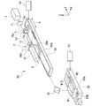
- FIG. 1A is a configuration diagram of a laser welding apparatus A including the optical scanning apparatus 2 according to the first embodiment.
- FIG. 2 is a plan view showing the locus of the laser beam L by the optical scanning device 2.
- the laser welding apparatus A of the present embodiment laser welds two metal workpieces W1 and W2 in a state where they are butted against each other.
- the welding device A includes a laser light irradiation device 1 (oscillator or the like) (light source) that irradiates the laser light L, and an optical scanning device 2 that scans the laser light L along the interface W12 of the workpieces W1 and W2. ing.
- the laser welding apparatus A includes an f ⁇ lens as a condensing lens for the laser beam L, which is designed so that the scanning speed is constant at the peripheral portion and the central portion of the lens. May be good.
- the laser beam L is wobbling along the interface W12. That is, the laser beam L is drawn (scanned) with a locus that combines circular motion and linear motion.
- the optical scanning device 2 illustrated in FIG. 1A has a rotary machine 10 (first rotary machine) and a rotary mirror 12 that carry out the circular motion, and two galvanometer mirrors 14 and 15 that carry out the linear motion. There is. On the irradiation surface of the laser beam L, one of the galvano mirrors 14 and 15 is responsible for scanning in the X-axis direction, and the other is responsible for scanning in the Y-axis direction.
- the rotary machine 10 includes a rotary shaft 11 that rotates around a rotary shaft R.
- the rotating machine 10 may be a spindle motor or an air turbine capable of rotating the rotating shaft 11 at high speed.
- the rotating machine 10 may be capable of rotating at a high speed of 100,000 [rpm] or more, for example.
- the X, Y, and Z axes shown in some figures are provided for convenience of explanation.
- the Y-axis indicates a direction parallel to the rotation axis R, and the X-axis and the Z-axis indicate a direction perpendicular to each other and perpendicular to the Y-axis.
- the XY plane corresponds to the horizontal plane and the Z axis corresponds to the vertical direction.
- the rotary mirror 12 is attached to the tip of the rotary shaft 11.
- the rotary mirror 12 is preferably a small circular mirror.
- the normal of the reflecting surface 12a of the rotating mirror 12 is inclined with respect to the rotating shaft R of the rotating shaft 11 (details will be described later).
- the laser beam L incident on the reflecting surface 12a of the rotating rotating mirror 12 is reflected at a certain angle and draws a circular locus. That is, the laser beam L reflected by the reflecting surface 12a of the rotating mirror 12 makes a circular motion.
- Galvano mirrors 14 and 15 move the circularly moving laser beam L in the XY planes set on the workpieces W1 and W2. That is, the galvanometer mirrors 14 and 15 play a role of linearly moving the circularly moving laser beam L on a plane along the interface W12. If the galvano mirrors 14 and 15 are used to make a circular motion of the laser beam L, it is necessary to rotate (vibrate) the galvano mirrors 14 and 15 finely at high speed, but the vibration is limited to about 1000 [Hz]. is there.
- the laser beam L reflected by the rotating mirror 12 is once reflected by the reflecting surface 13a of the optical path adjusting mirror 13 and then incident on the galvano mirror 14.
- a configuration may be adopted in which the distance D between the reflecting surface 13a of the optical path adjusting mirror 13 and the reflecting surface 12a of the rotating mirror 12 is variable.
- the angle between the normal of the reflecting surface 12a of the rotating mirror 12 and the rotating axis R of the rotating shaft 11 is ⁇ [rad]
- the optical path length from the reflecting surface 12a to the workpieces W1 and W2 is S [mm].
- a circle having a radius of ⁇ ⁇ S [mm] can be drawn on the target surfaces of the works W1 and W2.
- FIG. 1B is a modification of the laser welding apparatus A shown in FIG. 1A.
- the positions of the optical path adjusting mirror 13 and the optical scanning device 2 may be interchanged with each other.
- the optical scanning device 2 since the optical scanning device 2 can be arranged so as to be closer to the laser light irradiating device 1, the rigidity of the optical scanning device 2 can be more easily secured.
- an effect that the light reflected by the reflecting surface 12a of the rotating mirror 12 can be stabilized from the optical axis can be obtained.
- the locus of this circle is originally a perfect circle.
- the laser light L emitted from the laser light irradiation device 1 cannot be reflected in the same direction, it is necessary to incline the normal line of the reflection surface 12a with respect to the optical axis of the laser light L, although it is minute. is there. Therefore, the locus of the laser beam L becomes slightly elliptical. In the case of laser welding, even an ellipse of this size does not affect the welding performance, so it can be said that the shape collapses to a negligible level.
- the rotary mirror 12 attached to the tip of the rotary shaft 11 of the rotary machine 10 can draw a circle of the laser beam L at high speed, and thus is combined with the galvano mirrors 14 and 15.
- the wobbling locus as shown in FIG. 2 can be drawn at high speed, and the workpieces W1 and W2 can be satisfactorily laser welded in a short time.
- the galvano mirrors 14 and 15 are responsible for the linear motion of wobbling, but instead of the galvano mirrors 14 and 15, for example, a moving device for moving the workpieces W1 and W2 in a plane may be adopted. ..
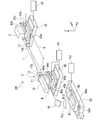
- FIG. 1C shows a laser adopting a configuration in which the distance D between the reflecting surface 13a of the optical path adjusting mirror 13 and the reflecting surface 12a of the rotating mirror 12 and the optical path length S from the reflecting surface 12a to the workpieces W1 and W2 are variable.
- the workpieces W1 and W2 are arranged on the workpiece moving apparatus 50.
- the laser welding device A2 provides a folded mirror 16 that folds back the optical path of the laser beam L so that the laser beam L reflected by the reflecting surface 13a of the optical path adjusting mirror 13 is scanned along the interface W12 of the workpieces W1 and W2. I have.
- the work moving device 50 includes a movable table 50a on which the works W1 and W2 are placed, and a shaft 50b that penetrates the movable table 50a and extends in the Y-axis direction.
- the movable table 50a can be moved along the shaft 50b by the control device 51.
- the work moving device 50 movable table 50a
- the laser light L can be scanned along the Y direction at the interface W12 of the works W1 and W2.
- the optical scanning apparatus 2 is parallel to the optical path adjusting mirror 13 that reflects the light reflected by the reflecting surface 12a of the rotating mirror 12 (along the Y-axis direction).
- a moving stage 70 (third moving stage) for moving the optical path adjusting mirror 13 and a control device 71 (third control device) for controlling the movement of the moving stage 70 are further provided.
- the moving stage 70 includes a base 70a, a movable table 70b that can move horizontally with respect to the base 70a, and a mirror holder 70c that is fixed to the movable table 70b and holds the optical path adjustment mirror 13.
- the movable table 70b can be moved on the base 70a in parallel with the rotation axis R (along the Y-axis direction) by the control device 71.
- the distance D between the reflecting surface 13a of the optical path adjusting mirror 13 and the reflecting surface 12a of the rotating mirror 12 is adjusted by the movement of the moving stage 70, and the optical path length S is adjusted so that the circle drawn on the work interface W12 is formed.
- the radius can be changed.
- scanning in the Y-axis direction at the work interface W12 can also be performed. Therefore, wobbling welding as illustrated in FIG. 2 can be performed at high speed on the work interface W12.
- the scanning width (welding width) at the work interface W12 can be changed by adjusting the optical path length S during the irradiation of the laser beam L.
- the optical scanning device 2 of FIG. 1C since the distance D can be adjusted while the position of the rotating machine 10 (rotating mirror 12) is fixed, it is easier to maintain the direction of the rotating shaft R of the rotating shaft 11.
- the radius of the circle drawn on the work interface W12 can be changed by adjusting the optical path length S, so that even when the mounting accuracy of the rotating mirror 12 on the rotating shaft 11 is not sufficient, The irradiation position of the laser beam L at the work interface W12 can be appropriately adjusted. As a result, the step of attaching the rotary mirror 12 to the rotary shaft 11 can be facilitated. Further, by adjusting the optical path length S, it is possible to obtain the optimum welding width (spot diameter and wobble width) and the penetration depth according to the material of the work and the welding form.
- the rotary machine 10, the work moving device 50, and the moving stage 70 may be controlled by one control device.
- the speed and width of the circular motion and the translational motion of the wobbling can be comprehensively adjusted by one control device, finer control of the wobbling becomes possible.
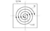
- FIG. 7 shows a spiral locus of the laser beam L (reflected light L2) on the reflecting surface 13a of the optical path adjusting mirror 13.
- the laser welding device A2 while irradiating the laser beam L, gradually reduce the distance D between the reflecting surface 12a of the rotating mirror 12 and the reflecting surface 13a of the optical path adjustment mirror 13 while fixing the positions of the workpieces W1 and W2. By separating them from each other, a spiral locus as illustrated in FIG. 7 can be drawn.
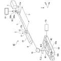
- FIG. 1D is a configuration diagram showing an example A3 of a laser welding apparatus adopting a configuration in which the optical path length S from the reflecting surface 12a to the workpieces W1 and W2 is variable.
- the laser welding apparatus A3 shown in FIG. 1D is different from the welding apparatus A2 described above in that the relative positional relationship between the reflecting surface 12a and the reflecting surface 13a is fixed, and the distance D is invariant. Since the configurations of the folding mirror 16 and the work moving device 50 are the same as those of the welding device A2, the description thereof will be omitted.
- the optical scanning apparatus 2 is parallel to the optical path adjusting mirror 13 that reflects the light reflected by the reflecting surface 12a of the rotating mirror 12 (along the Y-axis direction).
- a moving stage 80 fourth moving stage
- a control device 81 fourth control device
- the moving stage 80 includes a base 80a, a movable table 80b that can move horizontally with respect to the base 80a, a mirror holder 70c that is fixed to the movable table 80b and holds the optical path adjustment mirror 13, and a rotary machine 10 that is fixed to the movable table 80b.
- On the movable table 80b the relative positional relationship between the rotating machine 10 and the optical path adjusting mirror 13 (between the reflecting surface 12a and the reflecting surface 13a) is fixed.
- the movable table 80b can be moved on the base 80a in parallel with the rotation axis R (along the Y-axis direction) by the control device 81.
- the optical path length S from the reflecting surface 12a to the workpieces W1 and W2 (more directly, the optical path length from the reflecting surface 13a to the workpieces W1 and W2) is adjusted by moving the moving stage 80, thereby drawing on the work interface W12.
- the radius of the circle to be made can be changed.
- scanning in the Y-axis direction at the work interface W12 can also be performed. Therefore, wobbling welding as illustrated in FIG. 2 can be performed at high speed on the work interface W12.
- the scanning width (welding width) at the work interface W12 can be changed by adjusting the optical path length S during the irradiation of the laser beam L.
- the radius of the circle drawn on the work interface W12 can be changed by adjusting the optical path length S, so that the mounting accuracy of the rotating mirror 12 on the rotating shaft 11 is accurate. Is not sufficient, the irradiation position of the laser beam L at the work interface W12 can be appropriately adjusted. As a result, the process of attaching the rotary mirror 12 to the rotary shaft 11 can be simplified. Further, by adjusting the optical path length S, it is possible to obtain the optimum welding width (spot diameter and wobble width) and the penetration depth according to the material of the work and the welding form.
- the rotary machine 10, the work moving device 50, and the moving stage 80 may be controlled by one control device. In this case, since the speed and width of the circular motion and the translational motion of the wobbling can be comprehensively adjusted by one control device, finer control of the wobbling becomes possible.
- the optical scanning device and welding that are resistant to disturbance (vibration, etc.) Equipment can be provided. Further, since the distance D between the reflecting surface 12a of the rotating mirror 12 and the reflecting surface 13a of the optical path adjusting mirror 13 does not change even while the optical path length S is being adjusted by moving the moving stage 80, the laser on the reflecting surface 13a The magnitude of the locus of the light L is constant. Therefore, the size of the optical path adjustment mirror 13 can be suppressed to the minimum necessary, and the light scanning device 2 can be reduced in weight.
- the laser welding device A3 may include a condenser lens FL between the laser light irradiation device 1 and the rotating mirror 12.
- the optical path length from the laser light irradiation device 1 to the workpieces W1 and W2 does not change even while the optical path length S is being adjusted by moving the moving stage 80, the light is focused on the interface W12.
- the focused state of the lens FL can be maintained. That is, regardless of the adjustment operation of the optical path length S, the interface W12 can be stably irradiated with the laser beam having a high energy density.
- FIG. 3 is a diagram showing the positional relationship between the rotary machine 10, the rotary mirror 12, and the laser beam L according to the first embodiment.
- the normal line N of the reflecting surface 12a of the rotating mirror 12 is tilted at a first angle ⁇ 1 with respect to the optical axis of the incident light L1 incident on the reflecting surface 12a.
- the rotation axis R of the rotation shaft 11 is tilted at a second angle ⁇ 2 with respect to the normal line N of the reflection surface 12a.
- the magnitude (absolute value) of the first angle ⁇ 1 and the second angle ⁇ 2 are different.
- the first angle ⁇ 1 is larger than the second angle ⁇ 2.
- the optical axis of the incident light L1 is tilted with respect to the rotation axis R of the rotation shaft 11. That is, the optical axis of the incident light L1 and the rotation axis R of the rotation shaft 11 do not match.
- the incident position P of the incident light L1 on the reflecting surface 12a of the rotating mirror 12 coincides with the central position C through which the rotating shaft R of the rotating shaft 11 passes.
- the incident angle of the incident light L1 (first angle ⁇ 1) and the reflection angle of the reflected light L2 are the same with respect to the normal line N of the reflecting surface 12a passing through the incident position P.
- the normal line N of the reflection surface 12a rotates with an inclination of a second angle ⁇ 2 with respect to the rotation axis R of the rotation shaft 11.
- the reflected light L2 forms a conical reflection region 20 having an apex angle four times the second angle ⁇ 2 at the incident position P. That is, the locus of the bottom surface of the reflection region 20 (cone) becomes the locus of the circle described above.
- FIG. 4 shows the circular locus of the laser light L (reflected light L2) on the reflecting surface 13a of the optical path adjusting mirror 13.
- the optical scanning device 2 includes a rotary machine 10 including a rotary shaft 11 and a rotary mirror 12 attached to the tip of the rotary shaft 11, and is a method of a reflecting surface 12a of the rotary mirror 12.
- the line N is tilted at a first angle ⁇ 1 with respect to the optical axis of the incident light L1 incident on the reflecting surface 12a, and the rotating axis R of the rotating shaft 11 is a second angle with respect to the normal line N of the reflecting surface 12a. Since it is tilted at ⁇ 2, high-speed drawing (scanning) of a circular locus using the rotating machine 10 is possible.
- FIG. 5 shows a reflection region 20 of the reflected light L2 when the first angle ⁇ 1 and the second angle ⁇ 2 are equal.
- the first angle ⁇ 1 and the second angle ⁇ 2 are equal, and the optical axis of the incident light L1 and the rotation axis R of the rotation shaft 11 coincide with each other.
- the reflection region 20 of the reflected light L2 is formed around the optical axis of the incident light L1
- the optical path adjusting mirror 13 and the like illustrated in FIGS. 1A to 1C are placed around the incident light L1 (that is, the laser light irradiation device 1). It is necessary to devise such as arranging in a ring around (around). That is, a more complicated structure is required for the optical element on the downstream side of the rotating mirror 12.
- the first angle ⁇ 1 and the second angle ⁇ 2 are set so that the incident light L1 (that is, the laser light irradiation device 1) does not overlap the reflection region 20 of the reflected light L2. Should be set. Even when the rotation axis R of the rotating shaft 11 is translated (eccentric) with respect to the optical axis of the incident light L1, as long as the first angle ⁇ 1 and the second angle ⁇ 2 are equal, the rotation of the optical axis of the incident light L1 In addition, a reflection region 20 of the reflected light L2 is formed. In order to avoid the above complication, it is preferable that the first angle ⁇ 1 and the second angle ⁇ 2 are different regardless of whether the optical axis of the incident light L1 and the rotation axis R of the rotating shaft 11 match or do not match.
- the incident position P of the incident light L1 on the reflecting surface 12a of the rotating mirror 12 may coincide with the central position C through which the rotating shaft R of the rotating shaft 11 passes.
- the rotating shaft mounting surface 12b opposite to the reflecting surface 12a of the rotating mirror 12 may be a flat surface orthogonal to the rotating shaft R of the rotating shaft 11. According to this configuration, the rotary mirror 12 can be easily attached to the tip of the rotary shaft 11, and the assembleability of the optical scanning device 2 is improved. Further, each of the above-mentioned optical scanning devices 2 may be configured to move the incident position P of the incident light L1 on the reflecting surface 12a of the rotating mirror 12. When the laser light L is scanned along the interface W12 of the first work W1 and the second work W2 using each optical scanning device 2, the incident position P of the incident light L1 on the reflecting surface 12a of the rotating mirror 12 is moved. As a result, it is possible to prevent the incident light L1 from being continuously irradiated to a specific point on the reflecting surface 12a for a long time.
- FIG. 6A is a configuration diagram of the optical scanning apparatus 2 according to the second embodiment.
- the optical scanning device 2 illustrated in FIG. 6A is different from the first embodiment in that the rotating machine 10 is mounted on the moving device 30. Due to the movement of the moving device 30 in a plane perpendicular to the rotating shaft R, the distance between the incident position P of the incident light L1 and the central position C through which the rotating shaft R of the rotating shaft 11 passes is reduced on the reflecting surface 12a of the rotating mirror 12. It is variable.
- the thickness of the rotating mirror 12 two-dot chain line
- solid line the thickness of the rotating mirror 12
- the moving device 30 can be exemplified as, for example, a guide device that can move in one direction (regardless of a straight line or a curved line), a moving device that can move in two or more directions, and the like.
- the moving device 30 can also be driven under the control of the control device 31 to move the incident position P with respect to the central position C while the laser beam L is irradiating the rotating mirror 12.
- the laser beam L is continuously irradiated to a specific point on the reflecting surface 12a for a long time.
- the reflective surface 12a may be distorted by heat.
- the incident light L1 is incident on the reflecting surface 12a of the rotating mirror 12.
- the position P may be moved. For example, as shown by the alternate long and short dash line in FIG.
- the control device 31 moves the incident position P of the incident light L1 on the reflecting surface 12a of the rotating mirror 12 between the center position C through which the rotation axis R of the rotation shaft 11 passes and the position deviated from the center position C.
- the program may be incorporated in.
- the center position C can be kept in an appropriate temperature range by controlling the incident position P to be shifted from the center position C based on the result of the temperature measurement of the center position C by the control device 31.
- the temperature of the center position C can be measured by, for example, a temperature sensor (preferably a non-contact type) (not shown).
- the optical scanning device 2 illustrated in FIG. 6A is configured so that the rotating machine 10 can be moved by the moving device 30, the optical axis of the incident light L1 of the laser beam L may be movable.
- a mirror or a lens may be arranged between the laser light irradiation device 1 and the rotating mirror 12.
- FIG. 6B is a modification of the optical scanning apparatus 2 according to the second embodiment, and a configuration diagram of a laser welding apparatus A4 including the modified example.
- the rotary mirror 12 and the laser light irradiation apparatus 1 are configured to be movable in two directions (X-axis and Z-axis directions) perpendicular to the rotation axis R. Since the configurations of the folding mirror 16 and the work moving device 50 are the same as those of the welding devices A2 and A3, the description thereof will be omitted.
- the optical scanning device 2 moves the rotary machine 10 (rotary mirror 12) along a plane (XZ plane) perpendicular to the rotation axis R, and a moving stage 40 (first moving stage). ), And a control device 41 (first control device) that controls the movement of the movement stage 40.
- the control device 41 moves the incident position P of the incident light L1 on the reflecting surface 12a of the rotating mirror 12 between the center position C through which the rotation axis R of the rotation shaft 11 passes and the position deviated from the center position C.
- the movement of the movement stage 40 can be controlled.
- the optical scanning apparatus 2 includes a laser beam irradiating apparatus 1 (light source) that emits incident light L1 and a laser beam irradiating apparatus along a plane (XZ plane) perpendicular to the rotation axis R.
- a moving stage 42 (second moving stage) for moving 1 and a control device 43 (second control device) for controlling the movement of the moving stage 42 are further provided.
- the control device 43 moves the incident position P of the incident light L1 on the reflecting surface 12a of the rotating mirror 12 between the center position C through which the rotation axis R of the rotation shaft 11 passes and the position deviated from the center position C.
- the movement of the movement stage 42 can be controlled.
- the moving stages 40 and 42 have the same structure except for the bracket described later.
- the moving stage 40 (42) includes a first base 40a (42a), a movable table 40b (42b) that can move horizontally with respect to the base 40a (42a), and a second base fixed to the movable table 40b (42b). It includes a 40c (42c) and a movable table 40d (42d) that can be vertically moved with respect to the second base 40c (42c).
- the moving stage 40 further includes a bracket 40e that is fixed to the movable table 40d and holds the rotating machine 10.
- the laser light irradiation device 1 is fixed to the movable table 42d.
- the control device 41 (43) can control the movement of the movable table 40b (42b) with respect to the first base 40a (42a) in the X-axis direction. Further, the control device 41 (43) can control the movement of the movable table 40d (42d) with respect to the second base 40c (42c) in the Z-axis direction.
- the movement of the rotating machine 10 by the moving stage 40 and the movement of the laser light irradiation device 1 by the moving stage 42 are performed without tilting the rotating shaft R of the rotating shaft 11. Therefore, regardless of the movement of the rotary machine 10 and the laser light irradiation device 1, the rotary mirror 12 attached to the tip of the rotary shaft 11 can continue to rotate stably.
- the incident position P of the incident light L1 on the reflecting surface 12a of the rotating mirror 12 can be adjusted.
- the laser light irradiation device 1 fixed to the moving stage 42 by the control device 43 along a plane (XZ plane) perpendicular to the rotation axis R the incident light on the reflection surface 12a of the rotation mirror 12
- the incident position P of L1 can be adjusted.
- the control device 51 controls the incident position P to be shifted from the center position C based on the result of the temperature measurement at the center position C. Position C can be kept in an appropriate temperature range.
- the optical scanning device 2 of the laser welding device A4 may include at least one of the moving stages 40 and 42 illustrated in FIG. 6B.
- the moving stage 40 may include at least one of a portion (40a, 40b) responsible for movement in the X direction and a portion (40c, 40d) responsible for movement in the Z direction illustrated in FIG. 6B.
- the moving stage 42 may include at least one of a portion (42a, 42b) responsible for movement in the X direction and a portion (42c, 42d) responsible for movement in the Z direction illustrated in FIG. 6B.
- the condenser lens FL2 may be arranged between the folded mirror 16 and the works W1 and W2.
- the interface W12 can be stably irradiated with the laser light having a higher energy density.
- FIG. 6C is a modification of the optical scanning apparatus 2 according to the second embodiment, and a configuration diagram of a laser welding apparatus A5 including the modified example.
- the laser welding apparatus A4 illustrated in FIG. 6C is capable of shifting the optical axis of the laser beam L incident on the reflecting surface 12a of the rotating mirror 12 in a direction perpendicular to the rotating axis R (for example, the X-axis direction in FIG. 6C). It is configured. Since the configurations of the folding mirror 16 and the work moving device 50 are the same as those of the welding devices A2 to A4, the description thereof will be omitted.
- the optical scanning apparatus 2 rotates the transmission plate 60a arranged on the optical axis of the laser light L (incident light L1) and rotates the transmission plate 60a to parallel the optical axis.
- a transmission plate rotating device 60 including a second rotating machine 60b to be moved, and a rotation control device 61 for controlling the rotation of the second rotating machine 60b are provided.
- the rotation control device 61 the incident position P of the incident light L1 on the reflecting surface 12a of the rotating mirror 12 moves between the center position C through which the rotation axis R of the rotation shaft 11 passes and the position deviated from the center position C.
- the rotation of the second rotary machine 60b can be controlled.
- the transmission plate 60a is a plate that is transparent to the laser beam L.
- the incident angle of the laser light L with respect to the transmission plate 60a is other than 0 degrees, the laser light L is refracted by the transmission plate 60a.
- the optical axis of the laser beam L moves in parallel with the direction perpendicular to the rotation axis R (Y axis in FIG. 6C). That is, the rotation control device 61 controls the angle of the transmitting plate 60a with respect to the optical axis of the laser beam L through the second rotating machine 60b to adjust the incident position P of the incident light L1 on the reflecting surface 12a of the rotating mirror 12. it can. Since the operation of the transmission plate rotating device 60 does not involve the movement of the rotating machine 10, the rotating mirror 12 attached to the tip of the rotating shaft 11 can continue to rotate stably.
- the rotation control device 61 controls the incident position P to be shifted from the center position C based on the result of the temperature measurement at the center position C. Position C can be kept in an appropriate temperature range.
- the condenser lens FL2 may be arranged between the folded mirror 16 and the works W1 and W2.
- the interface W12 can be stably irradiated with the laser light having a higher energy density.
- the rotating shaft mounting surface 12b on the opposite side of the rotating mirror 12 from the reflecting surface 12a is an inclined surface parallel to the reflecting surface 12a and inclined with respect to the rotating shaft R of the rotating shaft 11. You may be.
- the thickness of the rotary mirror 12 can be reduced and the weight can be reduced as compared with the form in which the rotary shaft mounting surface 12b illustrated in FIG. 5 is orthogonal to the rotary shaft R. Therefore, the rotary mirror 12 can be easily rotated at high speed.
- Examples of the laser light irradiation device 1 described above include a normal single-mode laser and a single-mode fiber laser.
- a collimator unit may be arranged between the laser light irradiation device 1 and the rotary mirror 12 in order to obtain parallel light.
- FIGS. 9A to 9D There are various forms of welding of the workpieces W1 and W2 as shown in FIGS. 9A to 9D.
- FIG. 9 (a) is an example of butt welding, (b) is an example of lap welding, (c) is an example of worship welding, and (d) is an example of LIB (lithium ion battery) welding.
- the optical scanning device 2 according to each of the above-described embodiments can be used not only for butt welding but also for various types of welding as illustrated in FIGS. 9B to 9D.
- the surface of one of the works W1 is irradiated with laser light to perform welding at the interface W12.
- the optical scanning apparatus 2 and the welding apparatus provided with the optical scanning apparatus 2 can irradiate laser light at a desired position at high speed, they can be applied to welding of workpieces W1 and W2 of various materials.
- the workpieces W1 and W2 are a highly reflective material such as copper or aluminum that is difficult to weld, the above-mentioned wobbling welding is preferable.
- the high-speed laser light irradiation by the optical scanning device 2 can be applied to, for example, a manufacturing process of a lithium ion battery.
- a manufacturing process of a lithium ion battery in order to seal the can package into which the electrolytic solution is injected, there is a step (sealing step) in which a metal lid is overlapped and welded to the liquid injection port of the can package.
- welding defects due to adhesion of the electrolytic solution are very likely to occur, which makes stable mass production of lithium ion batteries difficult.
- the electrolytic solution adhering around the liquid injection port is effectively removed by using the optical scanning device 2 according to each of the above-described embodiments at the interface (contact surface) between the liquid injection port and the metal lid. be able to.
- the above-mentioned laser welding devices A2 and A3 to irradiate the interface (contact surface) between the injection port and the metal lid with high-speed laser light in a spiral locus as illustrated in FIG. , The electrolytic solution adhering around the injection port can be effectively removed.
- the laser beam is scanned along the peripheral edge of the injection port using the optical scanning device 2 according to each of the above-described embodiments. May be good.
- the electrolytic solution adhering around the liquid injection port can be removed in advance after the electrolytic solution is injected from the liquid injection port of the can package and before the sealing step with the metal lid is performed (preliminary irradiation step). ).
- the welding strength between the metal lid and the liquid injection port in the sealing process can be further increased.
- a cap body having the liquid injection port is superposed on the metal can having the opening so as to close the opening, and the interface between the metal can and the cap body is used by using the optical scanning device 2 according to each of the above-described embodiments.
- the can package can be obtained by scanning the laser beam along the can package. More specifically, after housing a lithium-ion battery component such as an electrode coil in a metal can, a can package having a liquid injection port is formed by welding the peripheral edge of the opening of the metal can and a cap body having a liquid injection port. Can be obtained (can package manufacturing process). Welding in the can package manufacturing step described above, electrolytic solution removal in the pre-irradiation step, and welding in the sealing step can be realized by the same optical scanning device 2.
- the material of the metal can, the cap body, and the metal lid may be any of aluminum, stainless steel, and iron. Typically, the materials of the metal can, the cap body, and the metal lid are the same. High-speed wobbling of laser light using the optical scanning device 2 according to each of the above-described embodiments is suitable for welding these metals.
- the reflecting surface of the rotating mirror 12 is performed.
- the incident position P of the incident light L1 in 12a may be moved. In this case, the heat distortion of the reflective surface 12a is suppressed, and as a result, the welding / electrolytic solution removal work for a long time becomes possible.
- the rotation axis R is used.
- the scanning width of light at the interface between welding targets or around the liquid injection port may be changed. In this case, optimum scanning (welding) can be performed according to the material to be irradiated with the laser beam L and the welding form.
- the optical scanning device 2 may be applied to other devices that irradiate light such as ultraviolet rays (UV).
- UV ultraviolet rays
- an optical scanning device capable of high-speed scanning of a locus including a circular motion, an optical scanning method, and a method for manufacturing a lithium ion battery.
- Optical scanning device 10 Rotating machine 11 ... Rotating shaft 12 ... Rotating mirror 12a ... Reflecting surface 12b ... Rotating shaft mounting surface C ... Center position L1 ... Incident light N ... Normal line P ... Incident position R ... Rotating axis ⁇ 1 ... 1 angle ⁇ 2 ... 2nd angle
Landscapes
- Physics & Mathematics (AREA)
- Optics & Photonics (AREA)
- General Physics & Mathematics (AREA)
- Engineering & Computer Science (AREA)
- Plasma & Fusion (AREA)
- Mechanical Engineering (AREA)
- Laser Beam Processing (AREA)
Abstract
L'invention concerne un dispositif de balayage optique ayant une première machine rotative équipée d'un arbre rotatif et un miroir rotatif monté sur l'extrémité de pointe de l'arbre rotatif. La normale de la surface réfléchissante du miroir rotatif est inclinée selon un premier angle par rapport à l'axe optique de la lumière incidente incidente sur la surface réfléchissante, et l'axe de rotation de l'arbre rotatif est incliné selon un second angle par rapport à la normale de la surface réfléchissante. Le premier angle est supérieur au second angle.
Applications Claiming Priority (2)
| Application Number | Priority Date | Filing Date | Title |
|---|---|---|---|
| JP2019042639 | 2019-03-08 | ||
| JP2019-042639 | 2019-03-08 |
Publications (1)
| Publication Number | Publication Date |
|---|---|
| WO2020184516A1 true WO2020184516A1 (fr) | 2020-09-17 |
Family
ID=72426279
Family Applications (1)
| Application Number | Title | Priority Date | Filing Date |
|---|---|---|---|
| PCT/JP2020/010036 Ceased WO2020184516A1 (fr) | 2019-03-08 | 2020-03-09 | Dispositif de balayage optique, procédé de balayage optique et procédé de fabrication de batterie au lithium-ion |
Country Status (1)
| Country | Link |
|---|---|
| WO (1) | WO2020184516A1 (fr) |
Cited By (1)
| Publication number | Priority date | Publication date | Assignee | Title |
|---|---|---|---|---|
| JP2025523147A (ja) * | 2022-07-29 | 2025-07-17 | ヌオーヴォ・ピニォーネ・テクノロジー・ソチエタ・レスポンサビリタ・リミタータ | シュラウド付きインペラを製造するための方法 |
Citations (7)
| Publication number | Priority date | Publication date | Assignee | Title |
|---|---|---|---|---|
| JPS62120370U (fr) * | 1986-01-24 | 1987-07-30 | ||
| JPH0219819A (ja) * | 1988-07-08 | 1990-01-23 | Nikon Corp | 角度制御装置 |
| JPH10202380A (ja) * | 1997-01-20 | 1998-08-04 | Toshiba Corp | レ−ザ溶接方法および二次電池容器の製法 |
| CN202649599U (zh) * | 2012-05-03 | 2013-01-02 | 山东大学 | 基于旋转镜技术改善激光匀光效果与抑制散斑装置 |
| JP2013140682A (ja) * | 2011-12-28 | 2013-07-18 | Toshiba Corp | 二次電池及び二次電池の製造方法 |
| JP2016075722A (ja) * | 2014-10-02 | 2016-05-12 | 大日本印刷株式会社 | 照明装置、光学モジュール及び投射装置 |
| JP2016075858A (ja) * | 2014-10-08 | 2016-05-12 | 大日本印刷株式会社 | 光走査装置、光学モジュール、照明装置および投射装置 |
-
2020
- 2020-03-09 WO PCT/JP2020/010036 patent/WO2020184516A1/fr not_active Ceased
Patent Citations (7)
| Publication number | Priority date | Publication date | Assignee | Title |
|---|---|---|---|---|
| JPS62120370U (fr) * | 1986-01-24 | 1987-07-30 | ||
| JPH0219819A (ja) * | 1988-07-08 | 1990-01-23 | Nikon Corp | 角度制御装置 |
| JPH10202380A (ja) * | 1997-01-20 | 1998-08-04 | Toshiba Corp | レ−ザ溶接方法および二次電池容器の製法 |
| JP2013140682A (ja) * | 2011-12-28 | 2013-07-18 | Toshiba Corp | 二次電池及び二次電池の製造方法 |
| CN202649599U (zh) * | 2012-05-03 | 2013-01-02 | 山东大学 | 基于旋转镜技术改善激光匀光效果与抑制散斑装置 |
| JP2016075722A (ja) * | 2014-10-02 | 2016-05-12 | 大日本印刷株式会社 | 照明装置、光学モジュール及び投射装置 |
| JP2016075858A (ja) * | 2014-10-08 | 2016-05-12 | 大日本印刷株式会社 | 光走査装置、光学モジュール、照明装置および投射装置 |
Cited By (1)
| Publication number | Priority date | Publication date | Assignee | Title |
|---|---|---|---|---|
| JP2025523147A (ja) * | 2022-07-29 | 2025-07-17 | ヌオーヴォ・ピニォーネ・テクノロジー・ソチエタ・レスポンサビリタ・リミタータ | シュラウド付きインペラを製造するための方法 |
Similar Documents
| Publication | Publication Date | Title |
|---|---|---|
| TWI551384B (zh) | Processing equipment and processing methods | |
| EP2923791B1 (fr) | Procédé d'usinage au laser | |
| JP6740267B2 (ja) | レーザ加工装置 | |
| EP0781622A2 (fr) | Procédé et appareil pour le soudage de pièces avec deux faisceaux laser ou plus dont on fait osciller les spots d'un cÔté de la direction de soudage à l'autre | |
| CN111954584B (zh) | 激光焊接方法以及激光焊接装置 | |
| JP2001276988A (ja) | レーザ加工装置 | |
| JPH07185866A (ja) | レーザビーム振動装置およびそれを備えたレーザ加工装置 | |
| CN113634925A (zh) | 一种激光旋切加工系统及方法 | |
| WO2019198443A1 (fr) | Dispositif de soudage au laser | |
| JP2021522072A (ja) | 3次元物体を製造するための装置及び方法 | |
| JP2025161977A (ja) | レーザ溶接方法及びレーザ溶接装置 | |
| JP2019141852A (ja) | レーザ照射装置、及び、レーザ加工方法 | |
| TW202017684A (zh) | 雷射光掃描裝置以及雷射加工裝置 | |
| CN110977159A (zh) | 一种形成环形光斑的激光光路组件 | |
| WO2020184516A1 (fr) | Dispositif de balayage optique, procédé de balayage optique et procédé de fabrication de batterie au lithium-ion | |
| JP2005254618A (ja) | 樹脂溶着装置 | |
| CN115768587B (zh) | 激光焊接方法以及激光焊接装置 | |
| WO2023069847A1 (fr) | Traitement laser radial à balayage avec réflexion biconique | |
| WO2014203489A1 (fr) | Procédé de scellage de canette externe et dispositif de scellage de canette externe | |
| JP2001191189A (ja) | レーザ溶接装置 | |
| JP2001287068A (ja) | レーザ切断トーチ | |
| JP6643442B1 (ja) | レーザ加工機及びレーザ加工方法 | |
| JP7713645B2 (ja) | レーザ溶接装置及びレーザ光の照射位置ずれの補正方法 | |
| CN117733354A (zh) | 一种激光头可摆动的材料表面激光磨平设备 | |
| JP2011255405A (ja) | レーザ照射方法および装置 |
Legal Events
| Date | Code | Title | Description |
|---|---|---|---|
| 121 | Ep: the epo has been informed by wipo that ep was designated in this application |
Ref document number: 20770816 Country of ref document: EP Kind code of ref document: A1 |
|
| NENP | Non-entry into the national phase |
Ref country code: DE |
|
| 122 | Ep: pct application non-entry in european phase |
Ref document number: 20770816 Country of ref document: EP Kind code of ref document: A1 |
|
| NENP | Non-entry into the national phase |
Ref country code: JP |