WO2020184591A1 - 卵殻と卵殻膜との分離方法及び分離装置 - Google Patents
卵殻と卵殻膜との分離方法及び分離装置 Download PDFInfo
- Publication number
- WO2020184591A1 WO2020184591A1 PCT/JP2020/010401 JP2020010401W WO2020184591A1 WO 2020184591 A1 WO2020184591 A1 WO 2020184591A1 JP 2020010401 W JP2020010401 W JP 2020010401W WO 2020184591 A1 WO2020184591 A1 WO 2020184591A1
- Authority
- WO
- WIPO (PCT)
- Prior art keywords
- eggshell
- container
- alkaline solution
- membrane
- eggshell membrane
- Prior art date
- Legal status (The legal status is an assumption and is not a legal conclusion. Google has not performed a legal analysis and makes no representation as to the accuracy of the status listed.)
- Ceased
Links
Images
Classifications
-
- A—HUMAN NECESSITIES
- A23—FOODS OR FOODSTUFFS; TREATMENT THEREOF, NOT COVERED BY OTHER CLASSES
- A23L—FOODS, FOODSTUFFS OR NON-ALCOHOLIC BEVERAGES, NOT OTHERWISE PROVIDED FOR; PREPARATION OR TREATMENT THEREOF
- A23L15/00—Egg products; Preparation or treatment thereof
-
- B—PERFORMING OPERATIONS; TRANSPORTING
- B03—SEPARATION OF SOLID MATERIALS USING LIQUIDS OR USING PNEUMATIC TABLES OR JIGS; MAGNETIC OR ELECTROSTATIC SEPARATION OF SOLID MATERIALS FROM SOLID MATERIALS OR FLUIDS; SEPARATION BY HIGH-VOLTAGE ELECTRIC FIELDS
- B03B—SEPARATING SOLID MATERIALS USING LIQUIDS OR USING PNEUMATIC TABLES OR JIGS
- B03B1/00—Conditioning for facilitating separation by altering physical properties of the matter to be treated
- B03B1/04—Conditioning for facilitating separation by altering physical properties of the matter to be treated by additives
-
- B—PERFORMING OPERATIONS; TRANSPORTING
- B03—SEPARATION OF SOLID MATERIALS USING LIQUIDS OR USING PNEUMATIC TABLES OR JIGS; MAGNETIC OR ELECTROSTATIC SEPARATION OF SOLID MATERIALS FROM SOLID MATERIALS OR FLUIDS; SEPARATION BY HIGH-VOLTAGE ELECTRIC FIELDS
- B03B—SEPARATING SOLID MATERIALS USING LIQUIDS OR USING PNEUMATIC TABLES OR JIGS
- B03B5/00—Washing granular, powdered or lumpy materials; Wet separating
- B03B5/28—Washing granular, powdered or lumpy materials; Wet separating by sink-float separation
- B03B5/30—Washing granular, powdered or lumpy materials; Wet separating by sink-float separation using heavy liquids or suspensions
- B03B5/32—Washing granular, powdered or lumpy materials; Wet separating by sink-float separation using heavy liquids or suspensions using centrifugal force
-
- B—PERFORMING OPERATIONS; TRANSPORTING
- B03—SEPARATION OF SOLID MATERIALS USING LIQUIDS OR USING PNEUMATIC TABLES OR JIGS; MAGNETIC OR ELECTROSTATIC SEPARATION OF SOLID MATERIALS FROM SOLID MATERIALS OR FLUIDS; SEPARATION BY HIGH-VOLTAGE ELECTRIC FIELDS
- B03B—SEPARATING SOLID MATERIALS USING LIQUIDS OR USING PNEUMATIC TABLES OR JIGS
- B03B5/00—Washing granular, powdered or lumpy materials; Wet separating
- B03B5/28—Washing granular, powdered or lumpy materials; Wet separating by sink-float separation
- B03B5/30—Washing granular, powdered or lumpy materials; Wet separating by sink-float separation using heavy liquids or suspensions
- B03B5/44—Application of particular media therefor
-
- B—PERFORMING OPERATIONS; TRANSPORTING
- B03—SEPARATION OF SOLID MATERIALS USING LIQUIDS OR USING PNEUMATIC TABLES OR JIGS; MAGNETIC OR ELECTROSTATIC SEPARATION OF SOLID MATERIALS FROM SOLID MATERIALS OR FLUIDS; SEPARATION BY HIGH-VOLTAGE ELECTRIC FIELDS
- B03B—SEPARATING SOLID MATERIALS USING LIQUIDS OR USING PNEUMATIC TABLES OR JIGS
- B03B5/00—Washing granular, powdered or lumpy materials; Wet separating
- B03B5/62—Washing granular, powdered or lumpy materials; Wet separating by hydraulic classifiers, e.g. of launder, tank, spiral or helical chute concentrator type
- B03B5/623—Upward current classifiers
-
- B—PERFORMING OPERATIONS; TRANSPORTING
- B03—SEPARATION OF SOLID MATERIALS USING LIQUIDS OR USING PNEUMATIC TABLES OR JIGS; MAGNETIC OR ELECTROSTATIC SEPARATION OF SOLID MATERIALS FROM SOLID MATERIALS OR FLUIDS; SEPARATION BY HIGH-VOLTAGE ELECTRIC FIELDS
- B03B—SEPARATING SOLID MATERIALS USING LIQUIDS OR USING PNEUMATIC TABLES OR JIGS
- B03B5/00—Washing granular, powdered or lumpy materials; Wet separating
- B03B5/62—Washing granular, powdered or lumpy materials; Wet separating by hydraulic classifiers, e.g. of launder, tank, spiral or helical chute concentrator type
- B03B5/66—Washing granular, powdered or lumpy materials; Wet separating by hydraulic classifiers, e.g. of launder, tank, spiral or helical chute concentrator type of the hindered settling type
Definitions
- the present invention relates to a separation method and a separation device for separating an eggshell and an eggshell membrane from an egg shell portion.
- the split eggshell part can be roughly divided into an eggshell containing calcium carbonate as a main component and an eggshell membrane containing protein as a main component.
- the eggshell is a raw material for calcium-fortified foods, hydroxyapatite raw materials, and other products using calcium.
- Eggshell membranes are used as raw materials for protein-enriched foods, cosmetic raw materials, and other products in which proteins are used. Since the components of the eggshell and the eggshell membrane are significantly different, it is important to separate the eggshell and the eggshell membrane in order to effectively utilize the eggshell part.
- the eggshell from which the egg white and the yolk have been separated is put into a jet mill to crush and dry the eggshell to crush the eggshell smaller than the eggshell membrane or to separate the eggshell membrane from the eggshell.
- a method has been proposed in which the eggshell and the eggshell membrane are separated by a vibrating sieve or an air flow classifier after peeling (Patent Document 1). In this method, the equipment becomes large because a jet mill is used, and the running cost increases because a large amount of energy is required for the separation operation.
- a crushing device for crushing the eggshell with the eggshell membrane with a water stream a liquid cyclone for separating the crushed eggshell and the eggshell membrane by a specific gravity difference
- a liquid cyclone for separating the crushed eggshell and the eggshell membrane by a specific gravity difference
- a liquid cyclone for separating the crushed eggshell and the eggshell membrane by a specific gravity difference
- a liquid cyclone for separating the crushed eggshell and the eggshell membrane by a specific gravity difference
- a liquid cyclone for separating the crushed eggshell and the eggshell membrane by a specific gravity difference
- a liquid cyclone for separating the crushed eggshell and the eggshell membrane by a specific gravity difference
- a liquid cyclone for separating the crushed eggshell and the eggshell membrane by a specific gravity difference
- a liquid cyclone for separating the crushed eggshell and the eggshell membrane by a specific gravity difference
- a liquid cyclone for separating the crushed eggshell and the eggshell membrane by a specific gravity difference
- an object of the present invention is to provide a separation method and a separation device capable of sufficiently separating eggshell and eggshell membrane even on a small scale by a simpler method than before.
- the present inventors have made the eggshell part after breaking the egg and taking out the yolk and the egg white, in other words, the eggshell with the eggshell membrane attached, alkaline. It was found that by putting the solution into a rotating water stream, it is possible to collectively achieve the separation of the eggshell membrane from the eggshell with the eggshell membrane attached and the separation of the eggshell and the eggshell membrane. The invention was completed.
- the present invention is the following [1] to [11].
- [1] Separation of eggshell and eggshell membrane which comprises a step of putting the eggshell to which the eggshell membrane is attached into a rotating water stream of an alkaline solution, which is a separation method for separating the eggshell and the eggshell membrane. how to.
- the method for separating [1] or [2], wherein the alkaline solution is an alkaline solution having a pH of 10 to 14.
- the separation method according to any one of [1] to [3], comprising a step of recovering eggshell membranes suspended in an alkaline solution.
- the separation method according to any one of [1] to [4], which comprises a step of collecting the precipitated eggshell.
- a method for separating eggshell and eggshell membrane which is characterized by recovering.
- a bottomed tubular container capable of accommodating an eggshell and an alkaline solution with an eggshell membrane attached, and a container provided near the bottom of the container so as to form a vortex of the alkaline solution in the container.
- An eggshell and an eggshell provided with an alkaline solution supply portion opened toward the surface and a hollow eggshell charging portion provided above the inside of the container in coaxial with the center of the vortex of the alkaline solution.
- Separation device from the membrane [8]
- the separating device for eggshell and eggshell membrane of [7] which further includes a diffusion protrusion in the center of the bottom surface inside the container.
- the separating device for eggshell and eggshell membrane of [9] which is provided with at least one outlet in the recovery channel.
- the separating device for the eggshell and the eggshell membrane of [10] which is provided with a barrier around the discharge port.
- the method and apparatus for separating eggshell and eggshell membrane of the present invention can sufficiently separate eggshell and eggshell membrane even on a small scale by a simpler method than before.
- the method and apparatus for separating eggshell and eggshell membrane of the present invention makes it possible to obtain eggshell membrane in which deterioration due to oxidation or the like is suppressed.
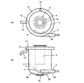
- FIG. 2A is a plan view of the apparatus
- FIG. 2B is a side view of the apparatus. It is a partially enlarged cross-sectional view of the separation device of the eggshell and the eggshell membrane of FIG.
- the separation method of the present invention is a separation method for separating an eggshell and an eggshell membrane, and is characterized by comprising a step of putting the eggshell to which the eggshell membrane is attached into a rotating water stream of an alkaline solution.
- the eggshell membrane is exfoliated from the eggshell by the action of the alkaline solution, and further, the eggshell membrane floats in the alkaline solution due to the difference in specific gravity, and the eggshell is precipitated, so that the eggshell and the eggshell membrane can be separated.
- the eggshell and eggshell membrane do not separate well, and the separation by specific gravity does not work.
- the floating eggshell membranes are washed away by a rotating stream of alkaline solution and eventually gather on the surface of the water.
- the rotating water flow of the alkaline solution is a vortex water flow with centrifugal force
- the suspended eggshell membranes gather on the water surface on the vortex water flow.
- eggshell membranes can be efficiently recovered.
- the eggshell membrane can be filtered out by allowing the alkaline solution to overflow from the container, providing a passage for the overflowing alkaline solution, and providing a filter, a net, etc. on the passage through which the overflowed alkaline solution passes. Can be recovered.
- the alkaline solution is not particularly limited, but an alkaline solution having a pH of 10 to 14 is preferable, and an alkaline aqueous solution having a pH of 10 to 14 is preferable. Further, since the separated and recovered eggshell membrane will be applied to cosmetics and foods, it is preferable that the alkaline aqueous solution can be used in the manufacturing process of cosmetics and foods.
- alkaline aqueous solution examples include sodium hydroxide aqueous solution, sodium carbonate aqueous solution, sodium hydrogen carbonate aqueous solution, ammonia aqueous solution, potassium hydroxide aqueous solution, calcium hydroxide aqueous solution, sodium acetate, ammonium carbonate aqueous solution, ammonium chloride aqueous solution and the like. ..
- the separation method of the present invention preferably includes a step of recovering eggshell membranes suspended in an alkaline solution.
- the eggshell membrane is filtered from the overflowing alkaline solution with a filter and a net, and the eggshell membrane is filtered by installing a filter or a net in the rotating water stream of the alkaline solution.
- Examples include a method of collecting the eggshell membrane and a method of sucking the eggshell membrane together with the alkaline solution.
- the separation method of the present invention preferably includes a step of collecting the precipitated eggshell.
- a recovery method a method of sucking the alkaline solution together with the precipitated eggshell using a pump or the like, a method of constructing the bottom of the container in which the eggshell is precipitated can be opened freely, and a method of discharging the precipitated eggshell together with the alkaline solution from the container. Can be mentioned.
- the step of putting in the eggshell to which the eggshell membrane is attached, the step of recovering the eggshell membrane, and the step of recovering the eggshell can be performed in parallel.
- the separation method of the present invention comprises a container having a bottomed cylindrical shape and an upper opening, an alkaline solution supply portion provided near the bottom surface of the side surface of the container, and the vicinity of the center of the opening above the container. It is a method of separating eggshell and eggshell membrane using an eggshell membrane separation device having an provided eggshell input portion.
- An alkaline solution is poured from the alkaline solution supply section to generate a rotating water flow of the alkaline solution in the container, and an eggshell with an eggshell membrane attached is charged from the eggshell charging section, and the eggshell membrane floating in the rotating water stream of the alkaline solution is charged.
- the method for separating the eggshell and the eggshell membrane is characterized by recovering.
- the bottomed cylindrical container with an open top has a circular cross section, and if the ratio of the radius of the circular bottom to the height of the side is low, the eggshell membrane is difficult to peel off.
- This eggshell membrane separation device preferably has a configuration in which the alkaline solution supply unit is opened toward the container in a direction capable of forming a vortex of the alkaline solution in the container, and a pump or the like is used from the alkaline solution supply unit. Then, when the alkaline solution is supplied into the container, the alkaline solution flows along the inner wall of the container and forms a vortex with centrifugal force to form a rotating water flow. More preferably, when the alkaline solution supply unit is installed so that the alkaline solution is discharged diagonally upward with respect to the bottom surface, the rotating water flow swirls upward from the bottom surface inside the container like a spiral staircase. The floating eggshell membrane can be moved upward in the container, that is, toward the water surface.
- a convex portion may be provided on the bottom surface of the container.
- the alkaline solution discharged from the alkaline solution supply unit collides with the convex portion, an upward water flow is generated, and the floating eggshell membrane can be moved upward in the container.
- the convex portion include a cone-shaped one provided at the bottom.
- this eggshell membrane separation device has a structure in which the upper part of the container is open and the alkaline solution overflows. As a result, the floating eggshell membrane overflows together with the overflowing alkaline solution. Therefore, the eggshell membrane can be efficiently recovered by providing a filter or a net on the passage of the overflowing alkaline solution.
- the eggshell membrane separation device has an eggshell charging portion provided near the center of the opening above the container.
- the eggshell charging section is, for example, a cylinder installed concentrically with the center of the container.
- the eggshell is thrown in from the upper part of the cylinder, the eggshell is thrown in near the bottom surface inside the container through the cylinder. Then, the eggshell and the eggshell membrane are separated by the action of the alkaline solution, and the eggshell membrane floats and flows along the rotating water stream and is separated from the eggshell.
- separation device for carrying out the method for separating eggshell and eggshell membrane of the present invention
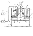
- the separation device 1 of the embodiment of the present invention shown in FIG. 1 is provided near the container 2 and the bottom of the container 2, and is opened toward the container in a direction capable of forming a vortex of an alkaline solution in the container 2.
- the container 2 has a bottom portion 2a and a cylindrical shape with an open upper portion, preferably a cylindrical shape.
- the material of the container 2 is not particularly limited, but it is preferably a metal material, particularly stainless steel, from the viewpoint of corrosion prevention and ease of handling.
- the size of the container is also not particularly limited, and can be made an appropriate size according to the processing amount of the eggshell with the eggshell membrane attached. An eggshell with an eggshell membrane attached to the container 2 is supplied, and an alkaline solution is supplied to separate the eggshell and the eggshell membrane in the container 2.
- the alkaline solution supply unit 3 is a device that supplies the alkaline solution into the container 2.
- the alkaline solution supply unit 3 is provided in the vicinity of the bottom portion 2a on the side surface of the container 2.
- An opening 3a is formed at a position on the side surface of the container 2 to which the alkaline solution supply unit 3 is connected.
- the alkaline solution is supplied into the container 2 from the alkaline solution supply unit 3 through the opening 3a.
- the alkaline solution supply unit 3 is connected to another tank in which the alkaline solution is stored in advance through a pipe, and a pump is built in the container 2 so that the alkaline solution can be supplied at a predetermined flow rate and flow velocity. Or, an external pump is connected.
- the alkaline solution supply unit 3 has a structure capable of forming a vortex in the container 2 by the liquid flow of the alkaline solution supplied in the container 2.
- a nozzle such that the liquid flow of the alkaline solution from the opening formed on the side surface of the container 2 toward the inside of the container 2 is tangential or close to the tangential direction of the inner side surface of the container 2.
- the structure may include a rectifying plate.
- An example of the direction of the flow of the alkaline solution supplied from the alkaline solution supply unit 3 into the container 2 is shown by an arrow A in FIG.
- the liquid flow of the alkaline solution from the alkaline solution supply unit 3 having such a structure toward the inside of the container 2 serves as a driving force to form a vortex of the alkaline solution in the container 2, and the vortex is thrown into the container 2. Since the eggshell with the eggshell membrane attached is agitated, the separation between the eggshell and the eggshell membrane is promoted.
- the alkaline solution supply unit 3 is preferably provided below the container 2 so that a sufficient vortex flow is formed in the container 2. Further, the alkaline solution supply unit 3 can be installed so that the alkaline solution is discharged diagonally upward with respect to the bottom surface. As a result, the rotating water flow flows upward from the inner bottom surface of the container while forming a vortex like a spiral staircase, and the floating eggshell membrane is moved upward in the container 2, that is, toward the water surface. Can be done.
- a diffusion protrusion 4 having a substantially conical shape is formed in the example shown as a convex portion.
- the diffusion protrusion 4 is arranged at the center of the inner bottom surface of the container 2 so that the apex of the cone-shaped diffusion protrusion 4 is located on the central axis of the vortex of the alkaline solution formed in the container 2. Is preferable.
- the alkaline solution discharged from the alkaline solution supply unit 3 collides with the diffusion protrusion 4, an upward water flow is generated, and the floating eggshell membrane is moved upward in the container. Can be done.
- the separation device 1 when the separation device 1 is used, the eggshell in the state where the eggshell membrane before separation that settles in the container 2 is attached moves along the side surface of the diffusion protrusion 4 toward the outer peripheral side in the radial direction on the bottom surface.
- the flow velocity of the vortex flow of the alkaline solution is relatively higher than that in the central portion, so that it is possible to prevent the eggshell with the eggshell membrane attached from staying at the bottom portion as it is. Therefore, since the eggshell with the eggshell membrane attached is stirred in the container 2 without precipitating, the separation between the eggshell and the eggshell membrane is promoted.
- the size of the diffusion protrusion 4 can be made an appropriate size according to the size of the container, the eddy current forming ability of the alkaline solution supply part 3, and the like.
- the alkaline solution should be below the height from the bottom surface to the apex of the diffusion protrusion 4. It is preferable that an opening on the side surface of the container 2 connected to the supply unit 3 is formed.
- an eggshell throwing portion 5 having at least an open lower end is provided.
- the eggshell charging portion 5 has a hollow shape and can have a cylindrical shape as an example, but is not limited to a cylindrical shape and may have a polygonal tubular shape.
- the eggshell charging portion 5 is arranged at a position where the central axis of the eggshell charging portion 5 is aligned with the radial center of the container 2 so that the center of the vortex flow formed in the container 2 is located inside the eggshell charging portion 5. Is preferable.
- the eggshell with the eggshell membrane attached is thrown from the upper part of the eggshell throwing part 5 toward the inner surface of the eggshell throwing part 5.
- the put-out eggshell with the eggshell membrane attached passes through the cylindrical eggshell throwing section 5. Therefore, it will be charged near the bottom surface inside the container 2. Then, it is agitated by the alkaline solution, and the eggshell and the eggshell membrane are separated by the action of the alkaline solution, and the eggshell membrane floats and flows along the rotating water stream and is separated from the eggshell.
- the eggshell membrane separated from the eggshell with the eggshell membrane attached in the container 2 tends to gather in the center due to a vortex because the specific gravity is relatively light.
- the eggshell membrane 5 It is possible to prevent the eggshell from gathering at the center, disperse it in an alkaline solution between the outer surface of the eggshell charging portion 5 and the inner surface of the container 2, and facilitate the floating toward the liquid surface due to the difference in specific gravity.
- the means for holding the eggshell charging portion 5 in a predetermined position in the container 2 includes, for example, a plurality of support columns 6 around the container 2 and a beam or a support plate 7 spanning the support columns 6. ,
- the eggshell throwing portion 5 can be suspended from the beam or the support plate 7 into the container 2.
- a lid may be provided above the upper end of the container 2 as needed, and the eggshell charging portion 5 may be attached to the lid.
- a plurality of locking tools that are fixed to the outer side surface of the eggshell charging portion 5 and extend radially can be provided, and these locking tools can be locked to the upper end of the container.
- a stirring blade 8 can be provided in the container 2 in order to promote stirring of the alkaline solution in the container 2.
- the stirring blade 8 is fixed near the lower end of the shaft 9 provided so as to penetrate the eggshell charging portion 5, and the diffusion blade 8 is arranged between the lower end of the eggshell charging portion 5 and the diffusion protrusion 4 in the container 2. Will be done.
- the upper end of the shaft 9 is connected to a motor 10 arranged above the container 2, and the driving force of the motor 10 is transmitted by the shaft 9 to rotate the stirring blade 8. It is preferable that the motor 10 rotates the stirring blade 8 in the forward and reverse directions.
- the separation between the eggshell and the eggshell membrane can be further promoted.
- a recovery channel 11 for eggshell membranes is provided on the outer side surface near the upper end of the container 2.
- FIG. 2 shows the main parts of the container 2 and its accessories in a plan view (FIG. 2A) and a side surface and (FIG. 2B).
- the eggshell charging portion 5 has been removed and is therefore shown by a virtual line.
- the recovery water channel 11 of the eggshell membrane has an annular groove provided in close contact with the outer side surface of the container 2 as a basic structure.
- the recovery channel 11 may be made of a metal material, but may be another material, for example a plastic material.
- a discharge port 12 is provided at least at one place on the bottom surface of the recovery water channel 11.
- a discharge pipe 13 is connected to the discharge port 12.
- the discharge pipe 13 can be made of a metal material, but may be another material such as a plastic material.
- the alkaline solution By continuing to supply the alkaline solution into the container 2 from the alkaline solution supply unit 3, the alkaline solution overflows from the upper end of the container 2 and is guided to the recovery water channel 11.
- the eggshell membrane separated from the eggshell with the eggshell membrane attached by being stirred by a vortex of the alkaline solution floats to the liquid surface of the alkaline solution in the container 2 due to the difference in specific gravity, and from the upper end of the container 2 together with the alkaline solution. It overflows and is guided to the recovery channel 11, and is recovered from the discharge port 12 through the discharge pipe 13 by, for example, the recovery device 18 shown in FIG.
- the eggshell membrane In the recovery device 18, the eggshell membrane is separated from the recovered mixture of the eggshell membrane and the alkaline solution by a filter and a net.
- a filter and a net can be provided in the container 2.
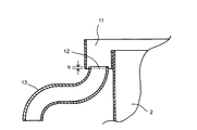
- FIG. 3 shows a partially enlarged cross-sectional view of the connection portion between the discharge port 12 of the recovery water channel 11 and the discharge pipe 13.
- One end of the discharge pipe 13 is inserted into the opening of the discharge port 12 from below the recovery water channel 11, so that the tip of the discharge pipe 13 is located above the bottom surface inside the groove of the recovery water channel 11. Is located in.
- the liquid that overflows from the upper end of the container 2 into the recovery channel 11 contains not only the eggshell membrane that has floated due to the difference in specific gravity, but also a relatively small eggshell that has floated in the container 2 by being agitated by a vortex.
- the eggshell contained in this liquid settles on the bottom surface of the groove of the recovery channel 11. Therefore, it is preferable to provide an eggshell barrier around the discharge port 12.
- the barrier is recovered from the discharge pipe 13 by arranging the tip of the discharge pipe 13 so as to be located above the bottom surface inside the groove of the recovery water channel 11. It is possible to significantly reduce the proportion of eggshell mixed in the eggshell membrane.
- the height from the inner bottom surface of the groove of the recovery water channel 11 to the tip of the discharge pipe 13 depends on the size of the container 2, the width of the groove of the recovery water channel 11, the amount of the alkaline solution supplied into the container 2, and the like. For example, it can be about 1 to 10 mm, preferably about 5 mm.
- FIG. 3 shows an example in which the tip of the drain pipe 13 is arranged so as to be located above the bottom surface inside the groove of the recovery water channel 11, but the structure of the drain port 12 and its vicinity is shown in FIG. It is not limited to the example shown in 3.
- a weir having a height of about 3 to 10 mm is formed around the drain port 12 inside the groove of the recovery water channel 11 to dam the eggshell, and the eggshell membrane overcomes this weir and the drain pipe is discharged from the drain port 12.
- the structure may be such that it leads to 13.
- a cleaning port 14 can be formed on the bottom surface of the groove of the recovery water channel 11 separately from the drain port 12, and a removable lid can be provided on the cleaning port 14. When cleaning the recovery water channel 11, the lid can be removed from the cleaning port 14, and the eggshell settled on the bottom surface of the recovery water channel 11 can be discharged from the cleaning port 14.
- the separation device 1 of the present embodiment including the container 2 provided with the recovery water channel 11 is provided with a workbench 15 for holding the container 2 as shown in FIG.
- the workbench 15 includes a support lower plate 15a facing the bottom surface of the container 2 and a plurality of columns 15b attached around the container 2, and the container 2 is held by the support lower plates 15a and the columns 15b. ing.
- the support column 15b is fixed to a support upper plate 15c in which a hole for accommodating the container 2 is formed. If necessary, the workbench 15 can make the container 2 tiltable. When the diameter and height of the container 2 exceed 1 m, the support upper plate 15c of the workbench 15 can be used as a floor surface for workers to work.
- the workbench 15 can be provided with stairs for getting on and off the support upper plate 15c of the worker. Further, a stationary caster can be provided at the lower end of the leg portion 15d of the workbench 15 to make the workbench 15 movable.
- a pump 16 for collecting the eggshell that has settled on or near the bottom surface of the container 2 is attached to the workbench 15 or is attached to the workbench. Prepared separately from 15.
- One end of the hose 17 is connected to the pump 16, and the other end of the hose 17 reaches near the bottom surface of the container 2.
- the type of the pump 16 is not limited, but in the gear pump, since the settled eggshell is in the form of sludge mixed with an alkaline solution, there is a concern that the sludge-like eggshell may damage the pump 16. Therefore, the pump 16 is preferably a hose pump.
- an openable and closable collection hole is formed in the bottom surface 2a of the container 2, and after the separation operation of the eggshell and the eggshell membrane, the container 2 Eggshells that have settled on or near the bottom surface of the inside may be discharged from the recovery hole.
- a recovery hole is formed on the bottom surface 2a of the container 2
- the eggshell may get caught in the collecting hole closing means, for example, the lid or the valve during operation and the egg shell may not be sufficiently closed, and the side downstream of the recovery hole. Piping may be clogged with eggshell sludge. Therefore, it is preferable to use the pump 16 and the hose 17 rather than the collection hole for collecting the eggshell in the container 2.
- a cleaning hole 2b can be further formed on the bottom surface 2a of the container 2.
- an opening / closing lid 2c that closes the cleaning hole 2b can be provided.
- the cleaning hole 2b can be formed so as to be located below the diffusion protrusion 4 provided on the bottom 2a of the container 2.
- the separation operation using the separation device 1 of the present embodiment will be described.
- the eggshell with the eggshell membrane attached to the inside of the container 2 is used for one operation from the eggshell charging portion 5 on the upper part of the container 2.
- the alkaline solution is supplied into the container 2 from the alkaline solution supply unit 3.
- the alkaline solution can be, for example, an alkaline aqueous solution having a pH of 10 to 14.
- the eggshell with the eggshell membrane attached can be subjected to preliminary treatment such as crushing before being placed in the container 2.
- the eggshell with the eggshell membrane attached may be put in one operation at a time, or the one operation may be divided into small portions or continuously added little by little.
- the liquid flow of the alkaline solution supplied from the alkaline solution supply unit 3 into the container 2 forms a vortex flow with centrifugal force in the container 2.
- the eggshell with the eggshell membrane attached is stirred in an alkaline solution to separate the eggshell and the eggshell membrane.
- the motor 10 is driven to rotate the stirring blade 8 near the lower end of the shaft 9 in the forward and reverse directions to further stir, and the separation between the eggshell and the eggshell membrane is promoted.
- the alkaline solution is continuously supplied into the container 2, and the alkaline solution and the separated eggshell membrane are overflowed from the upper end of the container 2 and guided to the recovery water channel 11, and the discharge port of the recovery water channel 11 is used as a step of recovering the eggshell membrane.
- the eggshell membrane is collected from 12 through the discharge pipe 13 by, for example, a collection device 18.
- the supply of the alkaline solution is stopped, the pump 16 is operated as a step of collecting the precipitated eggshell, and the container is passed through the hose 17. Collect the eggshell in 2. After the eggshell membranes are collected and the eggshell membranes are collected, the recovery channel 11 and the container 2 are cleaned to prepare for the next operation.
- the separation device 1 shown in FIG. 1 may be operated by one unit, a plurality of separation devices 1 may be prepared and operations may be started all at once, or the operation may be started sequentially at different times. May be good.
Landscapes
- Health & Medical Sciences (AREA)
- Nutrition Science (AREA)
- Life Sciences & Earth Sciences (AREA)
- Chemical & Material Sciences (AREA)
- Engineering & Computer Science (AREA)
- Food Science & Technology (AREA)
- Polymers & Plastics (AREA)
- Meat, Egg Or Seafood Products (AREA)
- Processing Of Solid Wastes (AREA)
- Separation Using Semi-Permeable Membranes (AREA)
- Separation Of Solids By Using Liquids Or Pneumatic Power (AREA)
Abstract
従来よりもシンプルな構造で小規模でも十分に卵殻と卵殻膜とを分離することができる方法を提供する。 卵殻と卵殻膜とを分離する分離方法であって、卵殻膜が付着した卵殻を、アルカリ性溶液の回転水流中に投入する工程、を備える。
Description
本発明は、卵の卵殻部から卵殻と卵殻膜とを分離する分離方法及び分離装置に関する。
卵、なかでも鶏卵を用いる食品工場等において、卵を割殻して卵黄と卵白とを取り出した後の卵殻部を有効利用することについて研究開発が進められ、現実に卵殻部を原料とした製品が発売されている。割殻された卵殻部は炭酸カルシウムを主成分とする卵殻と蛋白質を主成分とする卵殻膜とに大別でき、卵殻は、カルシウム強化食品、ハイドロキシアパタイト原料、その他のカルシウムが用いられる製品の原料等に用いられ、卵殻膜は、プロテイン強化食品、化粧品原料、その他の蛋白質が用いられる製品の原料等に用いられる。卵殻と卵殻膜とは成分が大きく異なることから卵の卵殻部を有効利用するためには、卵殻と卵殻膜とを分離することが重要である。
卵殻と卵殻膜とを分離する処理方法に関し、卵白及び卵黄を分離した卵殻をジェットミルに投入することにより卵殻の粉砕と乾燥を行って卵殻を卵殻膜よりも小さく粉砕し又は卵殻から卵殻膜を剥離させ、その後、振動ふるい機や気流分級装置によって卵殻と卵殻膜とを分離する方法が提案されている(特許文献1)。この方法は、ジェットミルを用いるために設備が大掛かりになり、また、分離操業に大量のエネルギーを要するためにランニングコストが嵩む。
また、卵殻と卵殻膜との分離方法及びその装置に関し、卵殻膜付きの卵殻を水流で粉砕する粉砕装置と、粉砕された卵殻と卵殻膜とを比重差で分別する液体サイクロンと、液体サイクロンの下流側で卵殻を受入れ、卵殻に付着残存又は単独で混入した卵殻膜を比重差で分離する分離用タンクを備えるものがある(特許文献2)。この分離用タンクは、下端が下すぼまり状をなす円筒形のタンクを備え、このタンクの内部下方に攪拌羽根が設けられ、このタンクの底部にはタンク内に上昇水流を生起させる水供給装置が設けられている。この特許文献2に記載の分離方法及び装置は、液体サイクロンと分離用タンクとで二重に卵殻膜を分離するために分離効率はよいが、設備は大掛かりで複雑となる。
そこで、本発明は、従来よりもシンプルな方法で小規模でも十分に卵殻と卵殻膜とを分離することができる分離方法及び分離装置を提供することを目的とする。
本発明者らは、上記課題を解決すべく鋭意検討した結果、卵を割殻して卵黄と卵白とを取り出した後の卵殻部、換言すれば卵殻膜が付着した状態の卵殻、を、アルカリ性溶液の回転水流中に投入することにより、卵殻膜が付着した状態の卵殻からの卵殻膜の剥離と、卵殻と卵殻膜との分離を一括して達成することが可能となることを見いだし、本発明を完成するに至った。
本発明は、以下の[1]~[11]である。
[1]卵殻と卵殻膜とを分離する分離方法であって、卵殻膜が付着した卵殻を、アルカリ性溶液の回転水流中に投入する工程、を備えることを特徴とする卵殻と卵殻膜とを分離する方法。
[2]前記回転水流が、遠心力を伴う渦水流である[1]の分離方法。
[3]前記アルカリ性溶液が、pH10~14のアルカリ性溶液である[1]又は[2]の分離方法。
[4]アルカリ性溶液中に浮遊した卵殻膜を回収する工程を備える[1]~[3]のいずれかの分離方法。
[5]沈殿した卵殻を回収する工程を備える[1]~[4]のいずれかの分離方法。
[6]有底円筒形で上方が開口している容器と、該容器側面の底面に近い位置に設けられたアルカリ性溶液供給部と、該容器上方の開口部中心近傍に設けられた卵殻投入部とを有する卵殻膜分離装置を用いた卵殻と卵殻膜の分離方法であって、
アルカリ性溶液供給部からアルカリ性溶液を投入して、該容器内にアルカリ性溶液の回転水流を生じさせ、卵殻投入部から卵殻膜が付着した卵殻を投入し、アルカリ性溶液の回転水流中に浮遊する卵殻膜を回収することを特徴とする卵殻と卵殻膜との分離方法。
[7]卵殻膜が付着した状態の卵殻及びアルカリ性溶液を収容可能な有底筒形の容器と、該容器の底部近傍に設けられ、該容器内でアルカリ性溶液の渦流を形成し得る向きに容器に向けて開口されたアルカリ性溶液供給部と、該容器内の上方にて、アルカリ性溶液の渦流の中心部と同軸に設けられた中空の卵殻投入部と、を備えることを特徴とする卵殻と卵殻膜との分離装置。
[8]前記容器の内側の底面の中央に、拡散突起部を更に備える[7]の卵殻と卵殻膜との分離装置。
[9]前記容器の外周側に卵殻膜の回収水路を備える[7]又は[8]の卵殻と卵殻膜との分離装置。
[10]前記回収水路に少なくとも一か所の排出口を備える[9]の卵殻と卵殻膜との分離装置。
[11]前記排出口の周囲に、障壁が設けられている[10]の卵殻と卵殻膜との分離装置。
本発明の卵殻と卵殻膜との分離方法及び装置は、従来よりもシンプルな方法で小規模でも十分に卵殻と卵殻膜とを分離することができる。また、本発明の卵殻と卵殻膜との分離方法及び装置により、酸化などによる劣化が抑制された卵殻膜を得ることが可能となる。
本発明の卵殻と卵殻膜との分離方法(以下、単に「分離方法」ともいう。)について説明する。
本発明の分離方法は、卵殻と卵殻膜とを分離する分離方法であって、卵殻膜が付着した卵殻をアルカリ性溶液の回転水流中に投入する工程を備えることを特徴とするものである。アルカリ性溶液の作用により、卵殻から卵殻膜が剥離され、さらに、比重の違いにより、卵殻膜がアルカリ性溶液中に浮遊し、卵殻が沈殿するので、卵殻と卵殻膜とを分離することができる。溶液が水である場合には、卵殻と卵殻膜とがうまく剥離しないし、比重による分離も機能しない。
浮遊した卵殻膜は、アルカリ性溶液の回転水流に流され、やがて水面に集まってくる。
アルカリ性溶液の回転水流が、遠心力を伴う渦水流である場合、浮遊した卵殻膜は、渦水流に乗って水面に集まってくる。この作用を利用して、卵殻膜を効率良く回収することができる。例えば、アルカリ性溶液を容器からオーバーフローさせるようにし、オーバーフローしたアルカリ性溶液の通路を設け、オーバーフローしたアルカリ性溶液が通る通路上にフィルター、網などを設けることによって、卵殻膜を濾しとることができ、卵殻膜を回収することができる。
アルカリ性溶液は、特に制限されないが、pH10~14のアルカリ性溶液が好ましく、pH10~14のアルカリ性の水溶液が好ましい。また、分離回収した卵殻膜は、化粧品や食品に応用することになるので、アルカリ性の水溶液は、化粧品や食品の製造工程に使用可能なものが好ましい。
アルカリ性の水溶液としては、例えば、水酸化ナトリウム水溶液、炭酸ナトリウム水溶液、炭酸水素ナトリウム水溶液、アンモニア水溶液、水酸化カリウム水溶液、水酸化カルシウム水溶液、酢酸ナトリウム、炭酸アンモニウム水溶液、塩化アンモニウム水溶液、等が挙げられる。
アルカリ性の水溶液としては、例えば、水酸化ナトリウム水溶液、炭酸ナトリウム水溶液、炭酸水素ナトリウム水溶液、アンモニア水溶液、水酸化カリウム水溶液、水酸化カルシウム水溶液、酢酸ナトリウム、炭酸アンモニウム水溶液、塩化アンモニウム水溶液、等が挙げられる。
本発明の分離方法は、アルカリ性溶液中に浮遊した卵殻膜の回収工程を備えることが好ましい。回収方法としては、上記のように、オーバーフローしたアルカリ性溶液からフィルター、網によって卵殻膜を濾しとる方法のほか、アルカリ性溶液の回転水流中に、フィルターや網を設置して、卵殻膜を濾しとって回収する方法、卵殻膜をアルカリ性溶液ごと吸引する方法などが挙げられる。
本発明の分離方法は、沈殿した卵殻を回収する工程を備えることが好ましい。回収方法としては、沈殿した卵殻ごとアルカリ性溶液をポンプ等を利用して吸引する方法、卵殻が沈殿した容器の底部を開口自在に構成し、沈殿した卵殻をアルカリ性溶液ごと容器から排出する方法などが挙げられる。
なお、卵殻膜の付着した卵殻を投入する工程、卵殻膜を回収する工程、卵殻を回収する工程は同時並行で行うことが可能である。
なお、卵殻膜の付着した卵殻を投入する工程、卵殻膜を回収する工程、卵殻を回収する工程は同時並行で行うことが可能である。
また、本発明の分離方法は、有底円筒形で上方が開口している容器と、該容器側面の底面に近い位置に設けられたアルカリ性溶液供給部と、該容器上方の開口部中心近傍に設けられた卵殻投入部とを有する卵殻膜分離装置を用いた卵殻と卵殻膜の分離方法であって、
アルカリ性溶液供給部からアルカリ性溶液を投入して、該容器内にアルカリ性溶液の回転水流を生じさせ、卵殻投入部から卵殻膜が付着した卵殻を投入し、アルカリ性溶液の回転水流中に浮遊する卵殻膜を回収することを特徴とする卵殻と卵殻膜との分離方法であることが好ましい。
アルカリ性溶液供給部からアルカリ性溶液を投入して、該容器内にアルカリ性溶液の回転水流を生じさせ、卵殻投入部から卵殻膜が付着した卵殻を投入し、アルカリ性溶液の回転水流中に浮遊する卵殻膜を回収することを特徴とする卵殻と卵殻膜との分離方法であることが好ましい。
有底円筒形で上方が開口している容器は、断面が円形であり、円形の底部の半径と、側部の高さとの比率が低いと、卵殻膜が剥離しにくい。
この卵殻膜分離装置は、好ましくは、アルカリ性溶液供給部が、容器内でアルカリ性溶液の渦流を形成し得る向きに容器に向けて開口された構成とされ、アルカリ性溶液供給部から、ポンプ等を利用してアルカリ性溶液を容器内に供給すると、アルカリ性溶液が容器内壁に沿って流れ、遠心力を伴う渦となって回転水流が形成される。
さらに好ましくは、アルカリ性溶液供給部を、底面に対して斜め上方向にアルカリ性用液が吐出されるように設置すると、回転水流が、らせん階段のようにして、容器内底面から上方に向かって渦を形成しながら流れていき、浮遊する卵殻膜を容器内の上方、つまり水面に向かって移動させることができる。
アルカリ性溶液供給部を底面に対して斜め上方向にアルカリ性溶液供給部が吐出されるように設置する代わりに、容器底面に凸部を設けてもよい。これにより、アルカリ性溶液供給部から吐出されたアルカリ性溶液が、該凸部にぶつかり、上向きの水流が生まれて、浮遊する卵殻膜を容器内の上方に移動させることができる。凸部としては、底部に設けたコーン形状のものが挙げられる。
また、この卵殻膜分離装置は、容器上方が開口しており、アルカリ性溶液がオーバーフローする構成となっていることが好ましい。これにより、オーバーフローするアルカリ性溶液とともに、浮遊する卵殻膜もオーバーフローするため、オーバーフローしたアルカリ性溶液の通路上にフィルターや網を設けることによって、卵殻膜を効率良く回収することができる。
好ましくは、卵殻膜分離装置は、容器上方の開口部中心近傍に設けられた卵殻投入部を有する。卵殻投入部は、例えば、容器中心と同心上に設置される円筒である。円筒の上部から卵殻を投入すると、卵殻は円筒を通って、容器内部の底面付近に投入されることになる。そうすると、アルカリ性溶液の作用によって、卵殻と卵殻膜とが分離し、卵殻膜は回転水流にのって浮遊し、流れていき、卵殻と分離される。
以下、本発明の卵殻と卵殻膜との分離方法を実施するのに好適な分離装置(以下、単に「分離装置」ともいう。)の実施形態を、図面を用いて具体的に説明する。
図1に示す本発明の一実施形態の分離装置1は、容器2と、容器2の底部近傍に設けられ、該容器2内でアルカリ性溶液の渦流を形成し得る向きに容器に向けて開口されたアルカリ性溶液供給部3と、容器2の内側の底面の中央に設けられた拡散突起部4と、該容器2内の上方にて、アルカリ性溶液の渦流の中心部と同軸に設けられた中空の卵殻投入部5と、を備えている。
容器2は、図2(b)に示されるように底部2aを有し、上部が開口している筒形であり、好ましくは円筒形状を有している。容器2の材料は、特に限定されないが、腐食防止や取り扱いの容易さ等から金属材料、なかでもステンレス鋼とすることが好ましい。容器の大きさも特に限定されず、卵殻膜が付着した状態の卵殻の処理量に応じて適切な大きさとすることができる。容器2内に卵殻膜が付着した状態の卵殻を供給し、また、アルカリ性溶液を供給して、容器2内で卵殻と卵殻膜とを分離する。
アルカリ性溶液供給部3は、容器2内にアルカリ性溶液を供給する機器である。図1に示した実施形態の分離装置1においては、アルカリ性溶液供給部3は、容器2の側面の底部2a近傍に設けられている。容器2の側面における、アルカリ性溶液供給部3が接続されている箇所には、開口3aが形成されている。この開口3aを通してアルカリ性溶液供給部3から容器2内にアルカリ性溶液が供給されるようになっている。アルカリ性溶液供給部3は、あらかじめアルカリ性溶液が収容されている別のタンクと配管を通じて接続されていて、容器2内にアルカリ性溶液を、所定の流量、流速で供給できるように、ポンプが内蔵されるか、又は、外部ポンプが接続されている。
アルカリ性溶液供給部3は、容器2内に供給されるアルカリ性溶液の液流により、容器2内で渦流を形成できるような構造を有している。具体的には、一例として容器2の側面に形成された開口から容器2内に向かうアルカリ性溶液の液流が、容器2の内側の側面の接線方向又は接線方向に近い向きになるようなノズルや整流板を備える構造とすることができる。アルカリ性溶液供給部3から容器2内に供給されるアルカリ性溶液の液流の向きの一例を図2の矢印Aで示す。このような構造を有するアルカリ性溶液供給部3から容器2内に向かうアルカリ性溶液の液流が駆動力となって容器2内でアルカリ性溶液の渦流が形成され、この渦流により容器2内に投入された卵殻膜が付着した状態の卵殻が攪拌されるので、卵殻と卵殻膜との分離が促進される。容器2内で十分な渦流が形成されるように、アルカリ性溶液供給部3は、容器2の下方に設けられることが好ましい。
更に、アルカリ性溶液供給部3を、底面に対して斜め上方向にアルカリ性用液が吐出されるように設置することもできる。これにより、回転水流が、らせん階段のようにして、容器内底面から上方に向かって渦を形成しながら流れていき、浮遊する卵殻膜を容器2内の上方、つまり水面に向かって移動させることができる。
更に、アルカリ性溶液供給部3を、底面に対して斜め上方向にアルカリ性用液が吐出されるように設置することもできる。これにより、回転水流が、らせん階段のようにして、容器内底面から上方に向かって渦を形成しながら流れていき、浮遊する卵殻膜を容器2内の上方、つまり水面に向かって移動させることができる。
容器2の内側の底面には、凸部として図示した例では略円錐形を有している拡散突起部4が形成されている。コーン状の拡散突起部4の頂点が容器2内で形成されるアルカリ性溶液の渦流の中心軸線上に位置するように、拡散突起部4は容器2の内側の底面の中心部に配置されることが好ましい。
拡散突起部4を備えることにより、アルカリ性溶液供給部3から吐出されたアルカリ性溶液が、該拡散突起部4にぶつかり、上向きの水流が生まれて、浮遊する卵殻膜を容器内の上方に移動させることができる。また、分離装置1の使用時に、容器2内で沈降する分離前の卵殻膜が付着した状態の卵殻が拡散突起部4の側面に沿って底面における半径方向外周側に移動する。底面における半径方向外周側は、中心部に比べてアルカリ性溶液の渦流の流速が相対的に速いので、卵殻膜が付着した状態の卵殻がそのまま底部で滞留することを防止することができる。したがって、卵殻膜が付着した状態の卵殻が沈殿することなく容器2内で攪拌されるので、卵殻と卵殻膜との分離が促進される。
拡散突起部4の大きさは、容器の大きさやアルカリ性溶液供給部3の渦流形成能力等に応じて適切な大きさとすることができる。拡散突起部4とアルカリ性溶液供給部3との位置関係について、卵殻膜が付着した状態の卵殻の沈殿を防止するために、拡散突起部4の底面からの頂点までの高さ以下に、アルカリ性溶液供給部3と接続される容器2の側面の開口が形成されていることが好ましい。
拡散突起部4の上方に、少なくとも下端が開放されている卵殻投入部5が設けられている。卵殻投入部5は、中空形状であり、一例として円筒形とすることができるが、円筒形に限られず、多角筒形とすることもできる。卵殻投入部5は、容器2内で形成される渦流の中心が卵殻投入部5の内側に位置するように、卵殻投入部5の中心軸が容器2の半径方向中心部に合う位置に配置されることが好ましい。
卵殻投入部5の上部から当該卵殻投入部5の内面に向けて卵殻膜が付着した状態の卵殻を投入する。卵殻投入部5を備え、卵殻投入部5の内面に向けて卵殻膜が付着した状態の卵殻を投入することにより、投入された卵殻膜が付着した状態の卵殻は円筒の卵殻投入部5を通って、容器2内部の底面付近に投入されることになる。そうすると、アルカリ性溶液によって攪拌され、アルカリ性溶液の作用によって、卵殻と卵殻膜とが分離し、卵殻膜は回転水流にのって浮遊し、流れていき、卵殻と分離される。容器2内で卵殻膜が付着した状態の卵殻から分離された卵殻膜は、比重が相対的に軽いために渦流により中心に集まろうとするが、卵殻投入部5を備えることにより、卵殻膜の中心への集合を防止して、卵殻投入部5の外面と容器2の内面へとの間のアルカリ性溶液中で分散させ、比重差により液面に向けて浮上させ易くすることができる。
卵殻投入部5を容器2内の所定の位置に保持するための手段は、例えば、容器2の周囲に複数の支持柱6と、それらの支持柱6にかけ渡された梁又は支持板7を備え、その梁又は支持板7から卵殻投入部5が容器2内に吊り下げられるようにしたものとすることができる。また、容器2の上端より上方に蓋が、必要に応じて設けられるようにして、その蓋に卵殻投入部5が取り付けられたものとすることができる。さらに、卵殻投入部5の外側の側面と固着して放射状に延びる複数の係止具を備え、それらの係止具が容器の上端に係止されるものとすることができる。
容器2内のアルカリ性溶液の攪拌を促進するために、容器2内に攪拌羽根8を設けることができる。卵殻投入部5内を貫通して設けられたシャフト9の下端近傍に攪拌羽根8が固定されて、拡散羽根8が容器2内で卵殻投入部5の下端と拡散突起部4との間に配置される。シャフト9の上端は、容器2の上方に配置されたモータ10に接続されていて、このモータ10の駆動力がシャフト9により伝達されて攪拌羽根8を回転させる。モータ10は、攪拌羽根8を正逆可能に回転させるものとすることが好ましい。図1に示した分離装置1は、アルカリ性溶液供給部3により容器2内で渦流を形成して卵殻と卵殻膜との分離を促進しているところ、更に攪拌羽根8を備えて当該攪拌羽根8にて容器2内のアルカリ性溶液を攪拌することにより、卵殻と卵殻膜との分離を一層促進させることができる。
容器2の上端近傍の外側の側面には、卵殻膜の回収水路11が設けられている。図2に、容器2及びその付属機器の要部を平面図(同図(a))及び側面と(同図(b))に示す。図2(a)において、卵殻投入部5は取り外されているので仮想線で示されている。図2(a)の平面図に示されるように、卵殻膜の回収水路11は、容器2の外側の側面に密着して設けられた円環状の溝を基本構造とするものである。回収水路11は、金属材料とすることかできるが、他の材料、例えばプラスチック材料でもよい。その回収水路11の底面の少なくとも一か所に、排出口12が設けられている。排出口12には、排出パイプ13が接続されている。排出パイプ13は、金属材料とすることができるが、他の材料、例えばプラスチック材料でもよい。
容器2内にアルカリ性溶液供給部3からアルカリ性溶液を供給し続けることにより、アルカリ性溶液は容器2の上端から溢れて回収水路11に導かれる。アルカリ性溶液の渦流等で攪拌され卵殻膜が付着した状態の卵殻から分離された卵殻膜は、比重差により容器2内のアルカリ性溶液の液面まで浮上し、アルカリ性溶液と一緒に容器2の上端から溢れて(オーバーフローして)回収水路11に導かれ、排出口12から排出パイプ13を通して例えば図1に示された回収装置18により回収される。回収装置18は、回収された卵殻膜とアルカリ性溶液との混合液からフィルター、網によって卵殻膜が分離される。容器2内にフィルター、網を設けることもできる。
図3に、回収水路11の排出口12と排出パイプ13との接続部分の部分拡大断面図を示す。排出パイプ13の一方の端部が、回収水路11の下方から排出口12の開口に挿入されて、当該排出パイプ13の先端が、回収水路11の溝の内側の底面よりも上方に位置するように配置されている。
容器2の上端から回収水路11に溢れ出る液中には、比重差により浮上した卵殻膜ばかりでなく、容器2内で渦流により攪拌されて浮上した比較的小さな卵殻が含まれている。この液中に含まれる卵殻は、回収水路11の溝の底面に沈殿する。そこで、排出口12の周囲に卵殻の障壁が設けられることが好ましい。障壁は、具体的に図3に示した例では、排出パイプ13の先端が、回収水路11の溝の内側の底面よりも上方に位置するように配置されることで、排出パイプ13から回収される卵殻膜の中に、卵殻が混入する割合を大幅に低減させることができる。回収水路11の溝の内側の底面から排出パイプ13の先端までの高さは、容器2の大きさや回収水路11の溝の幅や容器2内に供給されるアルカリ性溶液の量などにもよるが、例えば1~10mm程度、好ましくは5mm程度とすることができる。
なお、図3では、排出パイプ13の先端が、回収水路11の溝の内側の底面よりも上方に位置するように配置した例を示しているが、排水口12及びその近傍の構造は、図3に示した例に限られない。例えば、回収水路11の溝の内側における排水口12の周囲に3~10mm程度の高さの堰を形成して卵殻を堰止めし、卵殻膜は、この堰を乗り越えて排水口12から排出パイプ13に導くような構造としてもよい。
回収水路11の溝の底面に、排水口12とは別に清掃口14を形成すると共に、この清掃口14に着脱可能な蓋を設けることができる。回収水路11の清掃時に、清掃口14から蓋を取り外し、回収水路11の底面に沈殿した卵殻を清掃口14から排出することができる。
上記回収水路11が設けられた容器2を備える本実施形態の分離装置1は、図1に示されるように容器2を保持する作業台15を備えている。作業台15は、容器2の底面に対向する支持下板15aと、容器2の周りに取り付けられた複数の支柱15bとを備え、これらの支持下板15a及び支柱15bとで容器2を保持している。支柱15bは、容器2を収容する穴が形成された支持上板15cに固定されている。必要に応じて、作業台15は、容器2を傾動可能なものとすることができる。容器2の直径や高さが1mを超える大きさのものである場合には、作業台15の支持上板15cは、作業員が作業をするための床面とすることができる。また、作業台15は作業員の支持上板15cに乗降するための階段を設けることができる。さらに、作業台15の脚部15dの下端に静止可能なキャスターを設けて、作業台15を移動可能にすることができる。
分離装置1を用いた卵殻と卵殻膜との分離操業後に、容器2内の底面及びその近傍に沈殿している卵殻を回収するためのポンプ16が、作業台15に取り付けられるか、又は作業台15とは別に用意される。ポンプ16にホース17の一端が接続され、ホース17の他端は、容器2の底面近傍まで届くようにしている。ポンプ16の種類は問わないが、ギヤポンプでは沈殿した卵殻はアルカリ性溶液が混ざったスラッジ状であるため、このスラッジ状の卵殻によるポンプ16の破損を生じることが懸念される。そこで、ポンプ16は、ホースポンプであることが好ましい。
容器2内の卵殻を回収するために、ポンプ16とホース17のとの代わりに、容器2の底面2aに開閉自在な回収穴を形成して、卵殻と卵殻膜との分離操業後に、容器2内の底面及びその近傍に沈殿している卵殻を、上記回収穴から排出してもよい。もっとも、容器2の底面2aに回収穴を形成すると、操業中に当該回収穴の閉塞手段、例えば蓋やバルブに卵殻が噛み込んで十分に閉塞できないおそれがあり、また、回収穴よりも下流側の配管が卵殻のスラッジで詰まるおそれがある。したがって、容器2内の卵殻の回収は、上記回収穴よりも上記ポンプ16及びホース17を用いることが好ましい。
もっとも、上記ポンプ16とホース17を備えたうえで、さらに容器2の底面2aに、清掃用穴2bを形成することができる。清掃用穴2bを形成する場合は、清掃用穴2bを塞ぐ開閉蓋2cを設けることができる。清掃用穴2bは、容器2の底部2aに設けられた拡散突起部4の下方に位置するように形成することができる。
本実施形態の分離装置1を用いた分離操業を説明する。
容器2の底面2aの清掃用穴2bを、開閉蓋2cで閉じた状態で、容器2内に卵殻膜が付着した状態の卵殻を容器2の上部の卵殻投入部5から一回の操業分の量を投入する。また、アルカリ性溶液供給部3から容器2内にアルカリ性溶液を供給する。アルカリ性溶液は、例えばpH10~14のアルカリ性の水溶液とすることができる。卵殻膜が付着した状態の卵殻は、容器2内に入れる前に、粉砕等の予備的な処理をすることができる。また、卵殻膜が付着した状態の卵殻は一回の操業分を一度に入れてもよいし、一回の操業分を小分けにしたり少しずつ連続的に入れたりしてもよい。また、容器2内に卵殻膜が付着した状態の卵殻を入れる時期と、アルカリ性溶液を供給する時期の先後は問わず、また重複していてもよいが、アルカリ性溶液の回転水流中に投入することが好ましい。
容器2の底面2aの清掃用穴2bを、開閉蓋2cで閉じた状態で、容器2内に卵殻膜が付着した状態の卵殻を容器2の上部の卵殻投入部5から一回の操業分の量を投入する。また、アルカリ性溶液供給部3から容器2内にアルカリ性溶液を供給する。アルカリ性溶液は、例えばpH10~14のアルカリ性の水溶液とすることができる。卵殻膜が付着した状態の卵殻は、容器2内に入れる前に、粉砕等の予備的な処理をすることができる。また、卵殻膜が付着した状態の卵殻は一回の操業分を一度に入れてもよいし、一回の操業分を小分けにしたり少しずつ連続的に入れたりしてもよい。また、容器2内に卵殻膜が付着した状態の卵殻を入れる時期と、アルカリ性溶液を供給する時期の先後は問わず、また重複していてもよいが、アルカリ性溶液の回転水流中に投入することが好ましい。
アルカリ性溶液供給部3から容器2内に供給されるアルカリ性溶液の液流により、容器2内で遠心力を伴う渦流を形成させる。この渦流によりアルカリ性溶液中で卵殻膜が付着した状態の卵殻を攪拌し、卵殻と卵殻膜とに分離させる。必要に応じてモータ10を駆動させてシャフト9の下端近傍の攪拌羽根8を正逆自在に回転させていっそう攪拌させ、卵殻と卵殻膜との分離を促進させる。
アルカリ性溶液を容器2内に連続的に供給して容器2の上端からアルカリ性溶液と分離後の卵殻膜とを溢れさせて回収水路11に導き、卵殻膜を回収する工程として回収水路11の排出口12から排出パイプ13を通して例えば回収装置18により卵殻膜を回収する。
所定期間経過して容器2から溢れるアルカリ性溶液中の卵殻膜が十分に少なくなったら、アルカリ性溶液の供給を停止して、沈殿した卵殻を回収する工程としてポンプ16を作動させてホース17を経て容器2内の卵殻を回収する。卵殻膜の回収及び卵殻膜の回収後は回収水路11及び容器2の清掃をして次回の操業に備える。
図1に示した分離装置1は、一個で操業してもよいし、複数個の分離装置1を用意して一斉に操業を開始してもよいし、時間をずらして順次に操業開始してもよい。
以上、本発明の分離装置を実施形態及び図面を用いて説明したが、本発明は、これらの実施形態及び図面に限定されることなく、幾多の変形が可能である。
1 分離装置
2 容器
3 アルカリ性溶液供給部
4 拡散突起部
5 卵殻投入部
6 支持柱
7 支持板
8 攪拌羽根
9 シャフト
10 モータ
11 回収水路
12 排出口
13 排出パイプ
14 清掃口
15 作業台
16 ポンプ
17 ホース
18 回収装置
2 容器
3 アルカリ性溶液供給部
4 拡散突起部
5 卵殻投入部
6 支持柱
7 支持板
8 攪拌羽根
9 シャフト
10 モータ
11 回収水路
12 排出口
13 排出パイプ
14 清掃口
15 作業台
16 ポンプ
17 ホース
18 回収装置
Claims (11)
- 卵殻と卵殻膜とを分離する分離方法であって、
卵殻膜が付着した卵殻を、アルカリ性溶液の回転水流中に投入する工程、
を備えることを特徴とする卵殻と卵殻膜とを分離する方法。 - 前記回転水流が、遠心力を伴う渦水流である請求項1記載の分離方法。
- 前記アルカリ性溶液が、pH10~14のアルカリ性溶液である請求項1又は2記載の分離方法。
- アルカリ性溶液中に浮遊した卵殻膜を回収する工程を備える請求項1~3のいずれか一項記載の分離方法。
- 沈殿した卵殻を回収する工程を備える請求項1~4のいずれか一項記載の分離方法。
- 有底円筒形で上方が開口している容器と、該容器側面の底面に近い位置に設けられたアルカリ性溶液供給部と、該容器上方の開口部中心近傍に設けられた卵殻投入部とを有する卵殻膜分離装置を用いた卵殻と卵殻膜の分離方法であって、
アルカリ性溶液供給部からアルカリ性溶液を投入して、該容器内にアルカリ性溶液の回転水流を生じさせ、
卵殻投入部から卵殻膜が付着した卵殻を投入し、
アルカリ性溶液の回転水流中に浮遊する卵殻膜を回収する
ことを特徴とする卵殻と卵殻膜との分離方法。 - 卵殻膜が付着した状態の卵殻及びアルカリ性溶液を収容可能な有底筒形の容器と、該容器の底部近傍に設けられ、該容器内でアルカリ性溶液の渦流を形成し得る向きに容器に向けて開口されたアルカリ性溶液供給部と、該容器内の上方にて、アルカリ性溶液の渦流の中心部と同軸に設けられた中空の卵殻投入部と、を備えることを特徴とする卵殻と卵殻膜との分離装置。
- 前記容器の内側の底面の中央に、拡散突起部を更に備える請求項7記載の卵殻と卵殻膜との分離装置。
- 前記容器の外周側に卵殻膜の回収水路を備える請求項7又は8記載の卵殻と卵殻膜との分離装置。
- 前記回収水路に少なくとも一か所の排出口を備える請求項9記載の卵殻と卵殻膜との分離装置。
- 前記排出口の周囲に、障壁が設けられている請求項10記載の卵殻と卵殻膜との分離装置。
Priority Applications (4)
| Application Number | Priority Date | Filing Date | Title |
|---|---|---|---|
| DK20770300.0T DK3939704T3 (da) | 2019-03-11 | 2020-03-10 | Fremgangsmåde og apparat til adskillelse af æggeskal og æggeskalsmembran fra hinanden |
| EP20770300.0A EP3939704B1 (en) | 2019-03-11 | 2020-03-10 | Method and apparatus for separating egg shell and egg shell membrane from each other |
| CN202080019955.5A CN113557092A (zh) | 2019-03-11 | 2020-03-10 | 蛋壳和蛋壳膜的分离方法及分离装置 |
| US17/438,054 US11964284B2 (en) | 2019-03-11 | 2020-03-10 | Method and apparatus for separating egg shell and egg shell membrane from each other |
Applications Claiming Priority (2)
| Application Number | Priority Date | Filing Date | Title |
|---|---|---|---|
| JP2019044109A JP6829484B2 (ja) | 2019-03-11 | 2019-03-11 | 卵殻と卵殻膜との分離方法及び分離装置 |
| JP2019-044109 | 2019-03-11 |
Publications (1)
| Publication Number | Publication Date |
|---|---|
| WO2020184591A1 true WO2020184591A1 (ja) | 2020-09-17 |
Family
ID=72427591
Family Applications (1)
| Application Number | Title | Priority Date | Filing Date |
|---|---|---|---|
| PCT/JP2020/010401 Ceased WO2020184591A1 (ja) | 2019-03-11 | 2020-03-10 | 卵殻と卵殻膜との分離方法及び分離装置 |
Country Status (6)
| Country | Link |
|---|---|
| US (1) | US11964284B2 (ja) |
| EP (1) | EP3939704B1 (ja) |
| JP (1) | JP6829484B2 (ja) |
| CN (1) | CN113557092A (ja) |
| DK (1) | DK3939704T3 (ja) |
| WO (1) | WO2020184591A1 (ja) |
Families Citing this family (2)
| Publication number | Priority date | Publication date | Assignee | Title |
|---|---|---|---|---|
| CN114471740B (zh) * | 2022-02-18 | 2023-08-22 | 吕梁学院 | 以鸡蛋壳膜为原料制备尿素氧化催化剂的生产装置 |
| JP7697176B1 (ja) * | 2024-02-06 | 2025-06-24 | バイオサイエンステクノロジー株式会社 | 新規な糖化合物又はその塩 |
Citations (6)
| Publication number | Priority date | Publication date | Assignee | Title |
|---|---|---|---|---|
| JPH01275512A (ja) * | 1988-04-27 | 1989-11-06 | Q P Corp | 可溶性卵殻膜の製法 |
| JP2011184269A (ja) * | 2010-03-10 | 2011-09-22 | Wada Kigata Seisakusho:Kk | 生物由来の石灰質物質からのタンパク質の除去方法および該方法により得られる固体状の炭酸カルシウムを含む樹脂組成物 |
| JP2013233120A (ja) * | 2012-05-10 | 2013-11-21 | Domo Corporation:Kk | 卵殻と卵殻膜との分離回収方法及び分離回収装置 |
| CN204560862U (zh) * | 2015-03-23 | 2015-08-19 | 林玉英 | 新型鸡蛋加工装置 |
| CN105639702A (zh) * | 2014-12-04 | 2016-06-08 | 侯森 | 鸡蛋加工机械 |
| CN107343752A (zh) * | 2017-08-26 | 2017-11-14 | 郭继安 | 鸡蛋加工机械 |
Family Cites Families (12)
| Publication number | Priority date | Publication date | Assignee | Title |
|---|---|---|---|---|
| GB962386A (en) * | 1963-04-08 | 1964-07-01 | Insinooritoimisto Engineeringb | An improved hydraulic classifier |
| US4111798A (en) * | 1976-11-30 | 1978-09-05 | Battelle Development Corporation | Separation of solids by varying the bulk density of a fluid separating medium |
| JPH07227551A (ja) | 1994-02-18 | 1995-08-29 | Shokuhin Sangyo Eco Process Gijutsu Kenkyu Kumiai | 卵殻の処理方法 |
| JP3305538B2 (ja) | 1994-10-25 | 2002-07-22 | キユーピー株式会社 | 卵殻と卵殻膜との分離方法およびその装置 |
| IL131927A (en) * | 1997-03-18 | 2003-03-12 | Penn State Res Found | Waste egg shell components recovery |
| WO2001066270A1 (en) | 2000-03-03 | 2001-09-13 | Ovogen, Llc | Method and apparatus for processing eggshells |
| US8418943B2 (en) | 2005-01-18 | 2013-04-16 | Biova, L.L.C. | Egg shell membrane separation |
| JP4802305B2 (ja) | 2009-07-17 | 2011-10-26 | 独立行政法人科学技術振興機構 | 浮遊分離装置及び方法並びにその利用製品の製造方法 |
| TWM405836U (en) | 2010-12-13 | 2011-06-21 | Yu-Kai Weng | Egg shell and egg membrane separation machine |
| CN103340441B (zh) | 2013-07-01 | 2015-05-27 | 北京二商健力食品科技有限公司 | 一种禽蛋壳膜分离设备 |
| US9873616B2 (en) * | 2014-09-02 | 2018-01-23 | Mark Daniel Toman | Method and apparatus for the enhanced separation of calcium eggshell from organic membrane |
| CN106616505A (zh) | 2016-12-13 | 2017-05-10 | 重庆市长寿区标杆养鸡股份合作社 | 蛋壳膜搅碎分离装置 |
-
2019
- 2019-03-11 JP JP2019044109A patent/JP6829484B2/ja active Active
-
2020
- 2020-03-10 DK DK20770300.0T patent/DK3939704T3/da active
- 2020-03-10 EP EP20770300.0A patent/EP3939704B1/en active Active
- 2020-03-10 WO PCT/JP2020/010401 patent/WO2020184591A1/ja not_active Ceased
- 2020-03-10 US US17/438,054 patent/US11964284B2/en active Active
- 2020-03-10 CN CN202080019955.5A patent/CN113557092A/zh active Pending
Patent Citations (6)
| Publication number | Priority date | Publication date | Assignee | Title |
|---|---|---|---|---|
| JPH01275512A (ja) * | 1988-04-27 | 1989-11-06 | Q P Corp | 可溶性卵殻膜の製法 |
| JP2011184269A (ja) * | 2010-03-10 | 2011-09-22 | Wada Kigata Seisakusho:Kk | 生物由来の石灰質物質からのタンパク質の除去方法および該方法により得られる固体状の炭酸カルシウムを含む樹脂組成物 |
| JP2013233120A (ja) * | 2012-05-10 | 2013-11-21 | Domo Corporation:Kk | 卵殻と卵殻膜との分離回収方法及び分離回収装置 |
| CN105639702A (zh) * | 2014-12-04 | 2016-06-08 | 侯森 | 鸡蛋加工机械 |
| CN204560862U (zh) * | 2015-03-23 | 2015-08-19 | 林玉英 | 新型鸡蛋加工装置 |
| CN107343752A (zh) * | 2017-08-26 | 2017-11-14 | 郭继安 | 鸡蛋加工机械 |
Non-Patent Citations (1)
| Title |
|---|
| See also references of EP3939704A4 * |
Also Published As
| Publication number | Publication date |
|---|---|
| JP2020146604A (ja) | 2020-09-17 |
| EP3939704B1 (en) | 2024-05-01 |
| US20220040704A1 (en) | 2022-02-10 |
| EP3939704A4 (en) | 2022-12-21 |
| CN113557092A (zh) | 2021-10-26 |
| JP6829484B2 (ja) | 2021-02-10 |
| DK3939704T3 (da) | 2024-05-27 |
| EP3939704A1 (en) | 2022-01-19 |
| US11964284B2 (en) | 2024-04-23 |
Similar Documents
| Publication | Publication Date | Title |
|---|---|---|
| CN104470614A (zh) | 旋转分离器 | |
| US20100236573A1 (en) | Method and apparatus for washing sand | |
| US4759854A (en) | Grit trap | |
| JP6829484B2 (ja) | 卵殻と卵殻膜との分離方法及び分離装置 | |
| JP2013527813A (ja) | 容器からラベルを除去するための方法および装置 | |
| KR20160125226A (ko) | 고체미립자 원심분리장치 및 이를 이용한 고액분리방법 | |
| JP6072320B2 (ja) | 縦型濾過濃縮機、該縦型濾過濃縮機を用いた濃縮設備および濃縮方法 | |
| CN209383532U (zh) | 一种化工废液除臭过滤离心机设备 | |
| JP3037689B1 (ja) | 横軸円筒型遠心分離機の回転筒の洗浄方法 | |
| EP1669140A1 (en) | Method of washing solid grain | |
| EP1675666B1 (en) | Grit trap | |
| JP5706851B2 (ja) | 濾材凝着物除去装置及び濾材凝着物除去方法 | |
| JP6763535B1 (ja) | 卵殻膜分離システム、及び卵殻膜分離方法 | |
| CN208742022U (zh) | 一种用于过滤接地棒电镀液的过滤机 | |
| KR100406929B1 (ko) | 난각 및 난각막의 분리, 회수 방법 및 장치 | |
| JP2001070832A (ja) | 遠心濃縮装置 | |
| WO1995021697A1 (en) | Centrifugal separations apparatus | |
| JP2006095401A (ja) | し渣処理装置 | |
| JP2000140705A (ja) | 遠心分離装置 | |
| JPH07213951A (ja) | 生ごみ処理装置 | |
| JPH03135486A (ja) | 粒状体の洗浄装置 | |
| CN117263422A (zh) | 一种纯水净化的预处理设备 | |
| JP5899340B1 (ja) | 縦型濾過濃縮機を用いた濃縮方法 | |
| AU697570B2 (en) | Centrifugal separations apparatus | |
| CN115920702A (zh) | 一种药学研究用固体粉末混合装置 |
Legal Events
| Date | Code | Title | Description |
|---|---|---|---|
| 121 | Ep: the epo has been informed by wipo that ep was designated in this application |
Ref document number: 20770300 Country of ref document: EP Kind code of ref document: A1 |
|
| NENP | Non-entry into the national phase |
Ref country code: DE |
|
| ENP | Entry into the national phase |
Ref document number: 2020770300 Country of ref document: EP Effective date: 20211011 |