WO2020184962A1 - Plateau pour canapé - Google Patents
Plateau pour canapé Download PDFInfo
- Publication number
- WO2020184962A1 WO2020184962A1 PCT/KR2020/003345 KR2020003345W WO2020184962A1 WO 2020184962 A1 WO2020184962 A1 WO 2020184962A1 KR 2020003345 W KR2020003345 W KR 2020003345W WO 2020184962 A1 WO2020184962 A1 WO 2020184962A1
- Authority
- WO
- WIPO (PCT)
- Prior art keywords
- sofa
- cup
- tray
- main body
- coupling
- Prior art date
- Legal status (The legal status is an assumption and is not a legal conclusion. Google has not performed a legal analysis and makes no representation as to the accuracy of the status listed.)
- Ceased
Links
Images


Classifications
-
- A—HUMAN NECESSITIES
- A47—FURNITURE; DOMESTIC ARTICLES OR APPLIANCES; COFFEE MILLS; SPICE MILLS; SUCTION CLEANERS IN GENERAL
- A47C—CHAIRS; SOFAS; BEDS
- A47C17/00—Sofas; Couches; Beds
- A47C17/86—Parts or details specially adapted for beds, sofas or couches not fully covered by any single one of groups A47C17/02 - A47C17/84
-
- A—HUMAN NECESSITIES
- A47—FURNITURE; DOMESTIC ARTICLES OR APPLIANCES; COFFEE MILLS; SPICE MILLS; SUCTION CLEANERS IN GENERAL
- A47C—CHAIRS; SOFAS; BEDS
- A47C7/00—Parts, details, or accessories of chairs or stools
- A47C7/62—Accessories for chairs
-
- A—HUMAN NECESSITIES
- A47—FURNITURE; DOMESTIC ARTICLES OR APPLIANCES; COFFEE MILLS; SPICE MILLS; SUCTION CLEANERS IN GENERAL
- A47C—CHAIRS; SOFAS; BEDS
- A47C7/00—Parts, details, or accessories of chairs or stools
- A47C7/62—Accessories for chairs
- A47C7/68—Arm-rest tables ; or back-rest tables
- A47C7/70—Arm-rest tables ; or back-rest tables of foldable type
-
- A—HUMAN NECESSITIES
- A47—FURNITURE; DOMESTIC ARTICLES OR APPLIANCES; COFFEE MILLS; SPICE MILLS; SUCTION CLEANERS IN GENERAL
- A47G—HOUSEHOLD OR TABLE EQUIPMENT
- A47G23/00—Other table equipment
- A47G23/02—Glass or bottle holders
-
- A—HUMAN NECESSITIES
- A47—FURNITURE; DOMESTIC ARTICLES OR APPLIANCES; COFFEE MILLS; SPICE MILLS; SUCTION CLEANERS IN GENERAL
- A47G—HOUSEHOLD OR TABLE EQUIPMENT
- A47G23/00—Other table equipment
- A47G23/06—Serving trays
-
- F—MECHANICAL ENGINEERING; LIGHTING; HEATING; WEAPONS; BLASTING
- F16—ENGINEERING ELEMENTS AND UNITS; GENERAL MEASURES FOR PRODUCING AND MAINTAINING EFFECTIVE FUNCTIONING OF MACHINES OR INSTALLATIONS; THERMAL INSULATION IN GENERAL
- F16B—DEVICES FOR FASTENING OR SECURING CONSTRUCTIONAL ELEMENTS OR MACHINE PARTS TOGETHER, e.g. NAILS, BOLTS, CIRCLIPS, CLAMPS, CLIPS OR WEDGES; JOINTS OR JOINTING
- F16B5/00—Joining sheets or plates, e.g. panels, to one another or to strips or bars parallel to them
- F16B5/06—Joining sheets or plates, e.g. panels, to one another or to strips or bars parallel to them by means of clamps or clips
-
- F—MECHANICAL ENGINEERING; LIGHTING; HEATING; WEAPONS; BLASTING
- F16—ENGINEERING ELEMENTS AND UNITS; GENERAL MEASURES FOR PRODUCING AND MAINTAINING EFFECTIVE FUNCTIONING OF MACHINES OR INSTALLATIONS; THERMAL INSULATION IN GENERAL
- F16B—DEVICES FOR FASTENING OR SECURING CONSTRUCTIONAL ELEMENTS OR MACHINE PARTS TOGETHER, e.g. NAILS, BOLTS, CIRCLIPS, CLAMPS, CLIPS OR WEDGES; JOINTS OR JOINTING
- F16B7/00—Connections of rods or tubes, e.g. of non-circular section, mutually, including resilient connections
- F16B7/02—Connections of rods or tubes, e.g. of non-circular section, mutually, including resilient connections with conical parts
Definitions
- the present invention relates to a tray for a sofa, and in detail, relates to a tray that can be fixedly mounted on a sofa to stably place a cup or cup containing water or beverage, and in particular, not the armrests at both ends of the sofa, but a center point of the sofa It relates to a tray for a sofa that improves the convenience of use by providing a structure that can be installed in the.
- the present invention relates to a cup holder for supporting a cup by a tilting operation, and a sofa tray including the same, and in detail, the holder for supporting the cup relates to a technology in which the side of the cup is supported by a tilting operation. It relates to a technology for providing a means for stably supporting a cup by applying it to a tray for a sofa.
- a sofa is a long chair with a backrest, and it means a chair in the form of a seat cushion wrapped in cloth or leather, etc. It is generally located in the living room of a house and is widely used as a place to watch TV in everyday life or as a place to rest. Has become.
- Cushion which is one of the characteristics of the sofa, provides comfort to the user sitting on the sofa because it is more abundant than the office chair, but it becomes difficult to stably place an object on the sofa due to the flickering of the cushion. In other words, it is impossible to put a cup of tea, coffee cup, or other beverage that is easy to pour on the sofa. In order to place these items stably, there is the inconvenience of using a separate table in front of the sofa for placing items.
- Fig. 1 is a shape shown in the utility model, which is a method of attaching and fixing a tray to an armrest for a sofa.
- the present invention is to solve the above problems, and an object of the present invention is to provide a cup holder having a structure capable of stably supporting the cup.
- the present invention is to solve the above problems, and an object of the present invention is to provide a sofa tray having a structure that can be easily fixed to any position such as a center point or an edge of a sofa and can be applied to all sofas of various structures. .
- a sofa tray comprising: a fixing member 120 having a coupling rod detachably inserted and mounted in the main body, and an insertion fixing portion 122 and 124 that is rotatably connected to the coupling rod and inserted into a gap of the sofa.
- the main body has a body coupling portion 112 to which the coupling rod 121 of the fixing member 120 is inserted and fixed, and the body coupling portion has a groove to which the coupling rod is inserted and fixed, but at different depths It may be made of a plurality of coupling members (112-1, 112-2, 112-3) having a groove of.
- the fixing member includes a spacer 123 provided between the coupling rod 121 and the insertion fixing portions 122 and 124, and the coupling rod and the spacer can be rotated relative to the first hinge H1. It is coupled, and the insertion fixing portion and the spacer are coupled to be able to rotate relative to the second hinge (H2).
- the second hinge is composed of a cylindrical first member 122a formed at one end of the insertion fixing portion and a second member 123a formed at one end of the spacer to be fitted and rotated while surrounding the first member. .
- the insertion fixing portions 122 and 124 are alternately curved in opposite directions, and when inserted into a gap in the sofa, the curved shape is compressed to exert elasticity, the first elastic member 122 and the second elastic member 124 Consists of
- the present invention is the main body 110; A receiving groove 150 for receiving a cup formed on the upper surface of the main body; And a tilting member 160 provided in the accommodating groove and supporting the cup, wherein the tilting member comprises a first supporting portion 161 respectively supporting a bottom portion of the cup and a side surface of the cup while forming an angle A second support 162; A central portion 163 connecting the first support portion 161 and the second support portion 162; And a tilting member coupling means formed in the central portion to allow the tilting member to be tiltably coupled to the receiving groove.
- the two portions divided by a symmetry line X-Y passing through the tilting axis are congruent.
- Friction members 161a and 162a are provided on upper surfaces of the first support 161 and the second support 162 to impart a frictional force to a place in contact with the cup.
- the center of gravity (CG) of the tilting member 160 is located outside the vertical axis (AB) passing through the tilting axis, and when the cup is removed from the tilting member, the second support part of the tilting member supporting the side of the cup ( 162 is tilted outward.
- the first support portion 161 and the second support portion 162 have a right angle or an obtuse angle, and the tilting member coupling means is formed of a shaft and a groove formed in either of the central portion and the receiving groove.
- the present invention also provides a tray for a sofa comprising the cup holder of the above configuration.
- a tray for a sofa that can accommodate cups or cups of beverages such as coffee can be easily and conveniently coupled to a desired position on the sofa, and the cup placed in the receiving groove on the tray is stably supported by the cup holder.
- the advantageous effect is exerted.
- the present invention provides a cup holder capable of stably receiving and supporting a beverage cup or cup through a tilting means by the above configuration.
- a cup holder capable of stably receiving and supporting a beverage cup or cup through a tilting means by the above configuration.
- an advantageous effect of stably supporting the cup placed in the receiving groove on the tray is exerted.
- FIG. 1 shows a storage device for a sofa according to the prior art
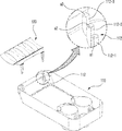
- FIG. 2 is a perspective view of a sofa tray according to an embodiment of the present invention
- FIG. 3 is a view of the sofa tray of FIG. 2 viewed from below
- FIGS. 4 and 5 are detailed views of some configurations of a tray for a sofa according to an embodiment of the present invention.
- FIG. 6 and 7 are enlarged views of portions A and B of FIG. 5, respectively, and are detailed views of the pivoting hinge portion,
- FIG. 12 is a view of a cup receiving groove provided in the tray for a sofa according to the present invention
- Figure 13 is a perspective view of a cup holder provided in the tray for a sofa according to the present invention
- FIG. 14 to 15 are views showing the tilting operation of the cup holder provided in the tray for a sofa according to the present invention.
- FIG. 16 shows a center of gravity and a symmetrical shape of a cup holder provided in a tray for a sofa according to the present invention.
- FIG 2 is a perspective view of a sofa tray according to an embodiment of the present invention
- Figure 3 is a view from the bottom of the sofa tray of Figure 2
- Figures 4 and 5 are for a sofa according to an embodiment of the present invention It is a detailed diagram of some configurations of the tray. Detailed enlarged views of the parts marked A and B in FIG. 5 are shown in FIGS. 6 and 7 and are detailed views of the hinge part.
- the present invention is a tray 100 that can be mounted at the center of the sofa, and is made of a main body 110 placed on the sofa and a fixing member 120 that fixes the main body to the sofa.
- the fixing member is characterized in that it is rotatable in a state coupled to the main body.
- the main body 110 has a receiving groove 115 capable of accommodating a cup or cup is formed on the upper surface, and other newspapers or magazines may also be placed on the upper surface.
- the fixing member 120 is composed of a coupling rod 121 detachably inserted and coupled to the main body 110, and insertion fixing portions 122 and 124 that are rotatably connected to the coupling rod and inserted into a gap of the sofa. .
- the main body of the present invention includes a main body coupling part 112 into which the coupling rod 121 of the fixing member 120 is inserted and fixed, and the main body coupling part includes the coupling rod. Grooves a1, a2, a3 to be inserted and fixed are formed.
- the main body coupling part 112 of the present invention may be one member having one groove into which the coupling rod is inserted, but may be formed of a plurality of coupling members 112-1, 112-2, and 112-3. Grooves a1, a2, and a3 of different depths are formed in each of the plurality of coupling members 112-1, 112-2, and 112-3. Through this, the coupling rod 121 is inserted into a groove of an appropriate depth among the plurality of coupling members 112-1, 112-2 and 112-3.
- the tray body 110 needs to adjust the depth to which the coupling rod is inserted in order to be placed on the sofa at an appropriate height.
- the user selects an appropriate place among the plurality of coupling members 112-1, 112-2, and 112-3, which is convenient.
- the fixing member 120 of the present invention will be described in detail with reference to FIGS. 4 to 5.
- the fixing member 120 includes a spacer 123 provided between the coupling rod 121 and the insertion fixing portions 122 and 124.
- a first hinge H1 is provided between the coupling rod and the spacer so that they can rotate relative to each other, and the insertion fixing part and the spacer are provided with a second hinge H2 to enable relative rotation. That is, the coupling rod 121 is rotatably coupled with respect to the spacer 123, and the insertion fixing portions 122 and 124 are also rotatably coupled with respect to the spacer 123.
- the first hinge H1 may be of any structure as long as it is rotatable in the left and right directions as shown in FIG. 6. Preferably, it is good to be able to rotate about 90° in both directions based on the spacer 123.
- the first hinge structure shown in FIG. 6 is an exemplary form, and various hinge structures are possible during the manufacturing process.
- FIG. 8 This is the form shown in FIG. 8 (mounted on the sofa) by rotating the spacer 123 to one side by 90° while the coupling rod 121 is fitted into the main body 110, or as shown in FIG. This is to enable the spacer 123 to be rotated about 90° to the other side (received state).
- FIG. 9 is a case in which the coupling member 120 enters the inside of the main body 110 and becomes a compact state, and the tray for sofa 100 of the present invention is accommodated in the house without being installed on the sofa, or It is intended to have a compact structure by reducing the volume in the process of selling and shipping trays.
- the second hinge is formed at one end of the cylindrical first member 122a and the spacer 123 formed at one end of the insertion fixing portions 122 and 124, and the first member It consists of a second member (123a) that rotates while being fitted while wrapping.
- the second member 123a has a round shape so as to be elastically coupled while surrounding the outer circumferential surface of the first member. Due to the structure of the second hinge H2, the insertion fixing parts 122 and 124 can be rotated at various angles (30°, 45°, 90°, etc.) with respect to the spacer 123.
- a sofa consists of a seat (S1 in FIG. 10) and a backrest (S2 in FIG. 10), and a gap (G in FIG. 10) exists between the seat (S1 and S2).
- the insertion fixing parts 122 and 124 of the present invention have a structure that is fitted and fixed in the gap G of the sofa.
- the gap G of the sofa may be formed at various angles with respect to the sofa seat. It may be formed to be parallel to the horizontal plane as shown in, or may be formed to form a 45° angle to the horizontal plane as shown in Fig. 11. In addition, although not shown, it may be formed to form an angle of 90° to the horizontal plane.
- the present invention allows the insertion and fixing portions 122 and 124 to be rotated at various angles based on the spacer so that it can be applied to all the structures of various sofas.
- the second hinge structure shown in FIG. 7 is an exemplary form, and it goes without saying that various types of hinge structures are possible in the manufacturing process.
- the insertion fixing portions 122 and 124 must have an elastic force so that they do not easily fall out when they are inserted into the gap G of the sofa.
- the insertion fixing portions 122 and 124 are alternately curved in opposite directions while having a first elastic member ( 122) and a second elastic member 124.
- first elastic member 122 and the second elastic member 124 are inserted into the sofa gap G, the curved shape is compressed and fixed so as not to be easily removed during the process of exerting elastic force.
- reference numeral 125 denotes a member to which the other ends of the first elastic member 122 and the second elastic member 124 are coupled.
- the present invention includes a receiving groove 150 for receiving a cup formed on the upper surface of the main body, and a tilting member 160 provided in the receiving groove and supporting the cup.
- the body and the tilting member 160 form a "cup holder".
- the tilting member is a member that supports the cup placed on the tray so that the cup is stably positioned.
- One or two or more tilting members positioned in the receiving groove are formed in an appropriate number, and preferably three are arranged on the outer peripheral surface of the cup.
- the tilting member 160 includes a first support portion 161 and a second support portion 162 supporting the cup, and a central portion 163 connecting the first support portion 161 and the second support portion 162.
- the first support 161 and the second support 162 have the same shape and are coupled to the center 163 to form an obtuse angle. As shown in FIG. 15, the first support 161 and the second support 162 support the bottom of the cup and the side of the cup when the cup is placed.
- the central portion 163 is provided with a tilting shaft 164 protruding to the side.
- a tilting shaft is coupled to a shaft coupling groove (not shown) provided in the cup receiving groove 150 to perform a tilting operation of the tilting member.
- the'tilting operation' refers to an operation in which the tilting member rotates (rotates) about the tilting axis by a predetermined angle when the cup is placed in the receiving groove 150 and when the cup is removed from the receiving groove. It refers to the operation of the tilting member shown in FIG. 15. That is, in the state in which the cup is not placed, the second support part 162 supporting the side of the cup of the tilting member is rotated to the outside (Fig.
- the second support part 162 is positioned to support the side of the cup.
- the support part 162 is located by rotating inward (FIG. 15), and this operation is referred to as a tilting operation in the present invention.
- the tilting member 160 includes two parts divided by a symmetric line X-Y passing through the tilting axis. That is, it is manufactured in a symmetrical shape based on the symmetry line, so that it can be easily assembled even if the assembly direction is reversed during the assembly process or during the process of installing on the sofa by the user.
- friction members 161a and 162a are provided on the upper surfaces of the first support 161 and the second support 162 to apply frictional force to a place in contact with the cup to stably support the cup.
- the center of gravity (CG) of the tilting member 160 is located outside the vertical axis (A-B) passing through the tilting axis, this is to automatically perform the tilting operation described above. That is, when the cup is removed from the tilting member, the tilting member tilts the second support portion 162 of the tilting member outward by its center of gravity.
- the present invention also relates to a tray for a sofa having the tilting member.
- the tilting member is not limited to the tray for the sofa, and it may be said that it belongs to the scope of the present invention if the cup holder having the tilting member is applied to the vehicle tray or other items.
- the present invention can be used industrially as a commercial tray that can be applied to a sofa or chair.
Landscapes
- Engineering & Computer Science (AREA)
- General Engineering & Computer Science (AREA)
- Mechanical Engineering (AREA)
- Health & Medical Sciences (AREA)
- General Health & Medical Sciences (AREA)
- Nursing (AREA)
- Chair Legs, Seat Parts, And Backrests (AREA)
Abstract
La présente invention concerne un plateau pour un canapé, le plateau pouvant être monté dans de multiples étages selon un espace dans le canapé ou la hauteur du canapé. Un porte-gobelet du plateau pour un canapé est doté d'un élément d'inclinaison et soutient de manière stable un gobelet sans secousses.
Applications Claiming Priority (4)
| Application Number | Priority Date | Filing Date | Title |
|---|---|---|---|
| KR10-2019-0027987 | 2019-03-12 | ||
| KR1020190027987A KR102196164B1 (ko) | 2019-03-12 | 2019-03-12 | 틸팅 동작으로 컵을 지지하는 컵홀더를 포함하는 소파용 트레이 |
| KR1020190027985A KR102196162B1 (ko) | 2019-03-12 | 2019-03-12 | 회동가능한 고정부재를 갖는 소파용 트레이 |
| KR10-2019-0027985 | 2019-03-12 |
Publications (1)
| Publication Number | Publication Date |
|---|---|
| WO2020184962A1 true WO2020184962A1 (fr) | 2020-09-17 |
Family
ID=72427175
Family Applications (1)
| Application Number | Title | Priority Date | Filing Date |
|---|---|---|---|
| PCT/KR2020/003345 Ceased WO2020184962A1 (fr) | 2019-03-12 | 2020-03-11 | Plateau pour canapé |
Country Status (1)
| Country | Link |
|---|---|
| WO (1) | WO2020184962A1 (fr) |
Cited By (1)
| Publication number | Priority date | Publication date | Assignee | Title |
|---|---|---|---|---|
| USD1074573S1 (en) | 2024-11-13 | 2025-05-13 | Yepz, Llc | Car tray |
Citations (5)
| Publication number | Priority date | Publication date | Assignee | Title |
|---|---|---|---|---|
| US20030106976A1 (en) * | 2001-12-12 | 2003-06-12 | Gebhard Then | Holder for vessels, especially drink containers |
| US6764053B1 (en) * | 2003-02-18 | 2004-07-20 | Sam Han | Object holder |
| US20060085917A1 (en) * | 1998-09-09 | 2006-04-27 | Jan Miller | Assist device for getting into and out of sitting or reclined positions |
| JP2011068173A (ja) * | 2009-09-24 | 2011-04-07 | Nippon Plast Co Ltd | 容器保持装置 |
| JP2013046648A (ja) * | 2011-08-29 | 2013-03-07 | Shogo Yabe | カップ・小物ホルダー |
-
2020
- 2020-03-11 WO PCT/KR2020/003345 patent/WO2020184962A1/fr not_active Ceased
Patent Citations (5)
| Publication number | Priority date | Publication date | Assignee | Title |
|---|---|---|---|---|
| US20060085917A1 (en) * | 1998-09-09 | 2006-04-27 | Jan Miller | Assist device for getting into and out of sitting or reclined positions |
| US20030106976A1 (en) * | 2001-12-12 | 2003-06-12 | Gebhard Then | Holder for vessels, especially drink containers |
| US6764053B1 (en) * | 2003-02-18 | 2004-07-20 | Sam Han | Object holder |
| JP2011068173A (ja) * | 2009-09-24 | 2011-04-07 | Nippon Plast Co Ltd | 容器保持装置 |
| JP2013046648A (ja) * | 2011-08-29 | 2013-03-07 | Shogo Yabe | カップ・小物ホルダー |
Cited By (1)
| Publication number | Priority date | Publication date | Assignee | Title |
|---|---|---|---|---|
| USD1074573S1 (en) | 2024-11-13 | 2025-05-13 | Yepz, Llc | Car tray |
Similar Documents
| Publication | Publication Date | Title |
|---|---|---|
| GB2411514A (en) | Elevation adjustment structure of a portable information display device | |
| WO2016144008A1 (fr) | Support intelligent pour chaise roulante | |
| WO2020184962A1 (fr) | Plateau pour canapé | |
| JP2025529326A (ja) | 電子機器アクセサリ | |
| CN210319210U (zh) | 移动终端支架 | |
| KR102196162B1 (ko) | 회동가능한 고정부재를 갖는 소파용 트레이 | |
| KR102196164B1 (ko) | 틸팅 동작으로 컵을 지지하는 컵홀더를 포함하는 소파용 트레이 | |
| WO2019083232A1 (fr) | Boîtier de produit cosmétique attachable à/détachable d'un dispositif mobile | |
| CN214093653U (zh) | 折叠支架 | |
| US11647843B2 (en) | Multifunctional sofa | |
| CN208657626U (zh) | 一种喂食碗 | |
| WO2011037430A9 (fr) | Dispositif de soutien du dos destiné à équiper une chaise | |
| CN214368858U (zh) | 移动设备支架 | |
| JPH08280544A (ja) | 運動均衡カバー付き食品加温器 | |
| CN221489644U (zh) | 一种具有防侧倾效果的抗摔水杯 | |
| CN206699823U (zh) | 安全桌 | |
| CN222061919U (zh) | 车门内饰板及车门 | |
| CN213940244U (zh) | 一种带有感应灯的多功能沙发 | |
| JPH0421504Y2 (fr) | ||
| CN222815529U (zh) | 一种带旋转摇动功能的折叠椅的支架结构 | |
| CN218338203U (zh) | 一种茶篮 | |
| CN218852128U (zh) | 一种旅行箱杯架 | |
| CN222052656U (zh) | 一种可旋转的无线磁电感应充电座 | |
| CN218355196U (zh) | 可收缩座椅填单台 | |
| KR102120428B1 (ko) | 휴대 단말기용 받침대 |
Legal Events
| Date | Code | Title | Description |
|---|---|---|---|
| 121 | Ep: the epo has been informed by wipo that ep was designated in this application |
Ref document number: 20770613 Country of ref document: EP Kind code of ref document: A1 |
|
| NENP | Non-entry into the national phase |
Ref country code: DE |
|
| 122 | Ep: pct application non-entry in european phase |
Ref document number: 20770613 Country of ref document: EP Kind code of ref document: A1 |