WO2020188902A1 - 二次電池 - Google Patents
二次電池 Download PDFInfo
- Publication number
- WO2020188902A1 WO2020188902A1 PCT/JP2019/047576 JP2019047576W WO2020188902A1 WO 2020188902 A1 WO2020188902 A1 WO 2020188902A1 JP 2019047576 W JP2019047576 W JP 2019047576W WO 2020188902 A1 WO2020188902 A1 WO 2020188902A1
- Authority
- WO
- WIPO (PCT)
- Prior art keywords
- battery
- secondary battery
- insulating
- insulating sheet
- current collector
- Prior art date
- Legal status (The legal status is an assumption and is not a legal conclusion. Google has not performed a legal analysis and makes no representation as to the accuracy of the status listed.)
- Ceased
Links
Images

Classifications
-
- H—ELECTRICITY
- H01—ELECTRIC ELEMENTS
- H01M—PROCESSES OR MEANS, e.g. BATTERIES, FOR THE DIRECT CONVERSION OF CHEMICAL ENERGY INTO ELECTRICAL ENERGY
- H01M50/00—Constructional details or processes of manufacture of the non-active parts of electrochemical cells other than fuel cells, e.g. hybrid cells
- H01M50/10—Primary casings; Jackets or wrappings
- H01M50/102—Primary casings; Jackets or wrappings characterised by their shape or physical structure
- H01M50/103—Primary casings; Jackets or wrappings characterised by their shape or physical structure prismatic or rectangular
-
- H—ELECTRICITY
- H01—ELECTRIC ELEMENTS
- H01M—PROCESSES OR MEANS, e.g. BATTERIES, FOR THE DIRECT CONVERSION OF CHEMICAL ENERGY INTO ELECTRICAL ENERGY
- H01M10/00—Secondary cells; Manufacture thereof
- H01M10/05—Accumulators with non-aqueous electrolyte
- H01M10/058—Construction or manufacture
- H01M10/0587—Construction or manufacture of accumulators having only wound construction elements, i.e. wound positive electrodes, wound negative electrodes and wound separators
-
- H—ELECTRICITY
- H01—ELECTRIC ELEMENTS
- H01M—PROCESSES OR MEANS, e.g. BATTERIES, FOR THE DIRECT CONVERSION OF CHEMICAL ENERGY INTO ELECTRICAL ENERGY
- H01M50/00—Constructional details or processes of manufacture of the non-active parts of electrochemical cells other than fuel cells, e.g. hybrid cells
- H01M50/10—Primary casings; Jackets or wrappings
- H01M50/147—Lids or covers
-
- H—ELECTRICITY
- H01—ELECTRIC ELEMENTS
- H01M—PROCESSES OR MEANS, e.g. BATTERIES, FOR THE DIRECT CONVERSION OF CHEMICAL ENERGY INTO ELECTRICAL ENERGY
- H01M50/00—Constructional details or processes of manufacture of the non-active parts of electrochemical cells other than fuel cells, e.g. hybrid cells
- H01M50/10—Primary casings; Jackets or wrappings
- H01M50/147—Lids or covers
- H01M50/148—Lids or covers characterised by their shape
- H01M50/15—Lids or covers characterised by their shape for prismatic or rectangular cells
-
- H—ELECTRICITY
- H01—ELECTRIC ELEMENTS
- H01M—PROCESSES OR MEANS, e.g. BATTERIES, FOR THE DIRECT CONVERSION OF CHEMICAL ENERGY INTO ELECTRICAL ENERGY
- H01M50/00—Constructional details or processes of manufacture of the non-active parts of electrochemical cells other than fuel cells, e.g. hybrid cells
- H01M50/10—Primary casings; Jackets or wrappings
- H01M50/183—Sealing members
- H01M50/186—Sealing members characterised by the disposition of the sealing members
- H01M50/188—Sealing members characterised by the disposition of the sealing members the sealing members being arranged between the lid and terminal
-
- H—ELECTRICITY
- H01—ELECTRIC ELEMENTS
- H01M—PROCESSES OR MEANS, e.g. BATTERIES, FOR THE DIRECT CONVERSION OF CHEMICAL ENERGY INTO ELECTRICAL ENERGY
- H01M50/00—Constructional details or processes of manufacture of the non-active parts of electrochemical cells other than fuel cells, e.g. hybrid cells
- H01M50/40—Separators; Membranes; Diaphragms; Spacing elements inside cells
-
- H—ELECTRICITY
- H01—ELECTRIC ELEMENTS
- H01M—PROCESSES OR MEANS, e.g. BATTERIES, FOR THE DIRECT CONVERSION OF CHEMICAL ENERGY INTO ELECTRICAL ENERGY
- H01M50/00—Constructional details or processes of manufacture of the non-active parts of electrochemical cells other than fuel cells, e.g. hybrid cells
- H01M50/40—Separators; Membranes; Diaphragms; Spacing elements inside cells
- H01M50/409—Separators, membranes or diaphragms characterised by the material
- H01M50/411—Organic material
- H01M50/414—Synthetic resins, e.g. thermoplastics or thermosetting resins
-
- H—ELECTRICITY
- H01—ELECTRIC ELEMENTS
- H01M—PROCESSES OR MEANS, e.g. BATTERIES, FOR THE DIRECT CONVERSION OF CHEMICAL ENERGY INTO ELECTRICAL ENERGY
- H01M50/00—Constructional details or processes of manufacture of the non-active parts of electrochemical cells other than fuel cells, e.g. hybrid cells
- H01M50/50—Current conducting connections for cells or batteries
- H01M50/572—Means for preventing undesired use or discharge
- H01M50/584—Means for preventing undesired use or discharge for preventing incorrect connections inside or outside the batteries
- H01M50/59—Means for preventing undesired use or discharge for preventing incorrect connections inside or outside the batteries characterised by the protection means
- H01M50/593—Spacers; Insulating plates
-
- H—ELECTRICITY
- H01—ELECTRIC ELEMENTS
- H01M—PROCESSES OR MEANS, e.g. BATTERIES, FOR THE DIRECT CONVERSION OF CHEMICAL ENERGY INTO ELECTRICAL ENERGY
- H01M10/00—Secondary cells; Manufacture thereof
- H01M10/04—Construction or manufacture in general
- H01M10/0431—Cells with wound or folded electrodes
-
- H—ELECTRICITY
- H01—ELECTRIC ELEMENTS
- H01M—PROCESSES OR MEANS, e.g. BATTERIES, FOR THE DIRECT CONVERSION OF CHEMICAL ENERGY INTO ELECTRICAL ENERGY
- H01M50/00—Constructional details or processes of manufacture of the non-active parts of electrochemical cells other than fuel cells, e.g. hybrid cells
- H01M50/10—Primary casings; Jackets or wrappings
- H01M50/172—Arrangements of electric connectors penetrating the casing
- H01M50/174—Arrangements of electric connectors penetrating the casing adapted for the shape of the cells
- H01M50/176—Arrangements of electric connectors penetrating the casing adapted for the shape of the cells for prismatic or rectangular cells
-
- H—ELECTRICITY
- H01—ELECTRIC ELEMENTS
- H01M—PROCESSES OR MEANS, e.g. BATTERIES, FOR THE DIRECT CONVERSION OF CHEMICAL ENERGY INTO ELECTRICAL ENERGY
- H01M50/00—Constructional details or processes of manufacture of the non-active parts of electrochemical cells other than fuel cells, e.g. hybrid cells
- H01M50/50—Current conducting connections for cells or batteries
- H01M50/531—Electrode connections inside a battery casing
- H01M50/533—Electrode connections inside a battery casing characterised by the shape of the leads or tabs
-
- H—ELECTRICITY
- H01—ELECTRIC ELEMENTS
- H01M—PROCESSES OR MEANS, e.g. BATTERIES, FOR THE DIRECT CONVERSION OF CHEMICAL ENERGY INTO ELECTRICAL ENERGY
- H01M50/00—Constructional details or processes of manufacture of the non-active parts of electrochemical cells other than fuel cells, e.g. hybrid cells
- H01M50/50—Current conducting connections for cells or batteries
- H01M50/572—Means for preventing undesired use or discharge
- H01M50/584—Means for preventing undesired use or discharge for preventing incorrect connections inside or outside the batteries
- H01M50/586—Means for preventing undesired use or discharge for preventing incorrect connections inside or outside the batteries inside the batteries, e.g. incorrect connections of electrodes
-
- Y—GENERAL TAGGING OF NEW TECHNOLOGICAL DEVELOPMENTS; GENERAL TAGGING OF CROSS-SECTIONAL TECHNOLOGIES SPANNING OVER SEVERAL SECTIONS OF THE IPC; TECHNICAL SUBJECTS COVERED BY FORMER USPC CROSS-REFERENCE ART COLLECTIONS [XRACs] AND DIGESTS
- Y02—TECHNOLOGIES OR APPLICATIONS FOR MITIGATION OR ADAPTATION AGAINST CLIMATE CHANGE
- Y02E—REDUCTION OF GREENHOUSE GAS [GHG] EMISSIONS, RELATED TO ENERGY GENERATION, TRANSMISSION OR DISTRIBUTION
- Y02E60/00—Enabling technologies; Technologies with a potential or indirect contribution to GHG emissions mitigation
- Y02E60/10—Energy storage using batteries
-
- Y—GENERAL TAGGING OF NEW TECHNOLOGICAL DEVELOPMENTS; GENERAL TAGGING OF CROSS-SECTIONAL TECHNOLOGIES SPANNING OVER SEVERAL SECTIONS OF THE IPC; TECHNICAL SUBJECTS COVERED BY FORMER USPC CROSS-REFERENCE ART COLLECTIONS [XRACs] AND DIGESTS
- Y02—TECHNOLOGIES OR APPLICATIONS FOR MITIGATION OR ADAPTATION AGAINST CLIMATE CHANGE
- Y02P—CLIMATE CHANGE MITIGATION TECHNOLOGIES IN THE PRODUCTION OR PROCESSING OF GOODS
- Y02P70/00—Climate change mitigation technologies in the production process for final industrial or consumer products
- Y02P70/50—Manufacturing or production processes characterised by the final manufactured product
Definitions
- This disclosure relates to a secondary battery.
- Patent Document 1 Conventionally, inventions relating to a square secondary battery that charges and discharges are known (see Patent Document 1 below).
- a flat winding group and a current collector plate connected to the winding group are covered with an insulating protective film and housed in a battery can.
- This conventional square secondary battery is characterized in that a heat-resistant film is provided between the insulating protective film and the current collector plate (see the same document, claim 1 and the like).
- the conventional square secondary battery is excellent in that the above-mentioned configuration can improve the insulation reliability by preventing the insulation protective film from melting without lowering the insertability of the winding group into the battery can. (See the same document, paragraph 0008, etc.).
- the insulating protective film is composed of a single sheet made of synthetic resin or a plurality of film members, and is oriented along the flat surface of the winding group and in the winding axis direction of the winding group. It is wound around the winding group with the orthogonal direction as the central axis direction (see the same document, paragraph 0022, FIG. 2, etc.).
- the insulating protective film may shift to the battery lid side due to contact with the battery can and be sandwiched between the battery lid and the battery can. If the battery lid and the battery can are welded in such a state, the welding between the battery lid and the battery can becomes insufficient, and the airtightness of the battery container may decrease.
- the present disclosure provides a secondary battery capable of ensuring the airtightness of the battery container more reliably than before.
- a wound body in which a positive electrode and a negative electrode are wound with a separator interposed therebetween, a pair of current collector plates connected to the positive electrode and the negative electrode, respectively, and the wound.
- a battery can accommodating a body and the current collector plate, a battery lid joined to an opening of the battery can, an insulating plate arranged between the current collector plate and the battery lid, and the battery can.
- An insulating sheet that covers the winder and the current collector plate inside, and a pair of external surfaces that are connected to each of the current collector plates and that penetrate the insulating plate and the battery lid and are exposed to the outside of the battery lid.
- a secondary battery comprising a terminal and having an end portion of the insulating sheet adjacent to the battery lid fixed to the insulating plate.
- FIG. 6 is a schematic cross-sectional view taken along the line IV-IV of the secondary battery shown in FIG.
- FIG. 6 is a schematic cross-sectional view taken along the line VV of the secondary battery shown in FIG.
- FIG. 6 is a schematic cross-sectional view corresponding to FIG. 4 of the secondary battery according to the second embodiment of the present disclosure.
- FIG. 5 is a schematic cross-sectional view corresponding to FIG. 5 of the secondary battery according to the second embodiment of the present disclosure.
- FIG. 6 is a schematic cross-sectional view corresponding to FIG.
- FIG. 5 is a schematic cross-sectional view corresponding to FIG. 5 of the secondary battery according to the third embodiment of the present disclosure.
- FIG. 5 is a schematic cross-sectional view corresponding to FIG. 5 of the secondary battery according to the fourth embodiment of the present disclosure. An enlarged view of the vicinity of the insulating plate of the secondary battery shown in FIG.
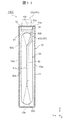
- FIG. 1 is a perspective view of the secondary battery 100 according to the first embodiment of the present disclosure.
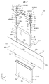
- FIG. 2 is an exploded perspective view of the secondary battery 100 shown in FIG.
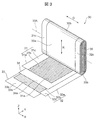
- FIG. 3 is an exploded perspective view of the winding body 30 of the secondary battery 100 shown in FIG.
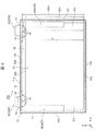
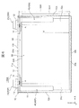
- FIG. 4 is a schematic cross-sectional view taken along the line IV-IV of the secondary battery 100 shown in FIG.
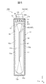
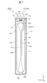
- FIG. 5 is a schematic cross-sectional view taken along the line VV of the secondary battery 100 shown in FIG.
- FIGS. 4 and 5 in order to clarify the positional relationship between each part of the secondary battery 100 and the insulating sheet 50, only the outer shape of the insulating sheet 50 is shown by a broken line.
- the secondary battery 100 of the present embodiment is, for example, an in-vehicle square secondary battery used in a power storage device of an electric vehicle (EV) or a hybrid electric vehicle (HEV). More specifically, the secondary battery 100 is, for example, a square lithium ion secondary battery. The secondary battery 100 is required to ensure airtightness more reliably. Although details will be described later, the secondary battery 100 of the present embodiment is characterized by the following configuration.
- the secondary battery 100 includes a winding body 30, a pair of current collector plates 40, a battery can 11, a battery lid 12, an insulating plate 14, an insulating sheet 50, and a pair of external terminals 20.
- the wound body 30 the positive electrode 31 and the negative electrode 32 are wound with the separators 33 and 34 interposed therebetween.
- the pair of current collector plates 40 are connected to the positive electrode 31 and the negative electrode 32, respectively.
- the battery can 11 houses the winding body 30 and the current collector plate 40.
- the battery lid 12 is joined to the opening 11a of the battery can 11.
- the insulating plate 14 is arranged between the current collector plate 40 and the battery lid 12.
- the insulating sheet 50 covers the winding body 30 and the current collector plate 40 inside the battery can 11.
- the pair of external terminals 20 are connected to the respective current collector plates 40, penetrate the insulating plate 14 and the battery lid 12, and are exposed to the outside of the battery lid 12.
- the secondary battery 100 is characterized in that the end portion 50e of the insulating sheet 50 adjacent to the battery lid 12 is fixed to the insulating plate 14.
- each part of the secondary battery 100 of the present embodiment will be described in detail.
- a three-dimensional Cartesian coordinate system consisting of an X-axis parallel to the width direction, a Y-axis parallel to the thickness direction, and a Z-axis parallel to the height direction of the flat-angle secondary battery 100 is used.
- the configuration of each part of the secondary battery 100 may be described.
- the directions such as up / down, left / right, and front / back in the following description are convenient directions for explaining the configuration of each part of the secondary battery 100 based on the drawings, and are not limited to the vertical direction and the horizontal direction. It does not limit the direction in which the secondary battery 100 is used.
- the secondary battery 100 includes, for example, a battery container 10, an external terminal 20, a winding body 30, a current collector plate 40, and an insulating sheet 50.
- the battery container 10 is, for example, a metal container having a flat rectangular box shape.
- the battery container 10 has a pair of wide side surfaces 10w along the width direction (X direction), a pair of narrow side surfaces 10n along the thickness direction (Y direction), and an elongated rectangular upper surface 10t and bottom surface 10b. Of these wide side surface 10w, narrow side surface 10n, top surface 10t and bottom surface 10b, the wide side surface 10w has the largest area.
- the battery container 10 has, for example, a flat square battery can 11 having one end open in the height direction (Z direction) and a rectangular plate-shaped battery lid 12 that closes the opening 11a of the battery can 11. ing.
- the winding body 30 which is a power storage element is inserted into the inside through the opening 11a of the battery can 11.
- the battery lid 12 is welded over the entire circumference of the opening 11a of the battery can 11 by laser welding, so that the opening 11a of the battery can 11 is sealed by the battery lid 12.
- the battery lid 12 has through holes 12a through which a part of the external terminal 20 is inserted at both ends in the longitudinal direction, which is the width direction (X direction) of the secondary battery 100. Further, the battery lid 12 has a gas discharge valve 15 at the center in the longitudinal direction.
- the gas discharge valve 15 is, for example, a portion in which a part of the battery lid 12 is pressed to be thinned to form a slit, and is provided integrally with the battery lid 12.
- the gas discharge valve 15 opens when the internal pressure of the battery container 10 rises to a predetermined pressure, and discharges the gas inside the battery container 10 to reduce the internal pressure of the battery container 10 and reduce the internal pressure of the battery container 10 to the secondary battery 100. To ensure the safety of.
- the battery lid 12 has, for example, a liquid injection hole 16 between the through hole 12a and the gas discharge valve 15.
- the liquid injection hole 16 is provided for injecting the electrolytic solution into the battery lid 12, and is sealed by joining the liquid injection plug 17 by, for example, laser welding after the injection of the electrolytic solution.
- a non-aqueous electrolytic solution to be injected into the battery container 10 for example, a non-aqueous electrolytic solution in which a lithium salt such as lithium hexafluorophosphate (LiPF 6 ) is dissolved in a carbonic acid ester-based organic solvent such as ethylene carbonate is used. Can be used.
- the pair of external terminals 20 are arranged apart from each other in the longitudinal direction of the outer surface of the battery lid 12, that is, the upper surface 10t of the battery container 10, penetrate the battery lid 12, and inside the battery container 10, each of the pair of current collector plates 40. It is connected to the base 41.
- the external terminal 20 includes a positive electrode external terminal 20P and a negative electrode external terminal 20N.
- the material of the positive electrode external terminal 20P is, for example, aluminum or an aluminum alloy.
- the material of the negative electrode external terminal 20N is, for example, copper or a copper alloy.
- the external terminal 20 has, for example, a joint portion 21 joined to the bus bar and a connecting portion 22 connected to the current collector plate 40.
- the joint portion 21 has a rectangular block shape having a substantially rectangular parallelepiped shape, and is arranged on the outer surface of the battery lid 12, that is, the upper surface 10t of the battery container 10 via a gasket 13 having electrical insulation.
- the connecting portion 22 is a columnar or cylindrical portion extending in a direction penetrating the battery lid 12 from the bottom surface of the joint portion 21 facing the battery lid 12.
- the current collector plate 40 is a plate-shaped member bent into a predetermined shape and is connected to the winding body 30.
- the current collector plate 40 includes a positive electrode current collector plate 40P that connects the positive electrode electrode 31 and the positive electrode external terminal 20P, and a negative electrode current collector plate 40N that connects the negative electrode electrode 32 and the negative electrode external terminal 20N.
- the material of the positive electrode current collector plate 40P is, for example, aluminum or an aluminum alloy.
- the material of the negative electrode current collector plate 40N is, for example, copper or a copper alloy.
- the current collector plate 40 is, for example, a joint portion 42a of a base portion 41 connected to the external terminal 20, an extension portion 42 extending in a direction intersecting the base portion 41, and an extension portion 42 joined to the winding body 30. It has a bent portion 43 provided between the base portion 41 and the base portion 41.
- the base 41 is arranged along the inner surface of the battery lid 12, and the extending portion 42 extends in a direction orthogonal to the inner surface of the battery lid 12.
- the bonding portion 42a of the extending portion 42 is bonded to the laminated portion 35 in which the positive electrode current collecting portion 31c or the negative electrode current collecting portion 32c of the winding body 30 is wound and laminated flat, for example, by ultrasonic bonding. Has been done.
- the wound body 30 includes, for example, a positive electrode 31, a negative electrode 32, and a first separator 33 and a second separator 34, which are insulators that insulate these electrodes.
- the winding body 30 is a winding electrode group having a structure in which a first separator 33, a positive electrode 31, a second separator 34, and a negative electrode 32 are laminated and wound in the winding direction R.
- the wound body 30 is formed into a flat shape for being accommodated in a flat square battery can 11, and has a flat portion 30a and a pair of curved portions 30b provided at both ends of the flat portion 30a. There is.
- the positive electrode 31, the negative electrode 32, and the separators 33, 34 are wound in a plane substantially parallel to the width direction (X direction) and the height direction (Z direction) of the secondary battery 100.
- the positive electrode 31, the negative electrode 32, and the separators 33, 34 constituting the winding body 30 are centered on the width direction of the secondary battery 100, that is, the axis substantially parallel to the winding shaft 30A. It is curved and wound in a semi-cylindrical shape.
- the electrodes wound around the innermost circumference and the outermost circumference are the negative electrode electrodes 32, and the first separator 33 is further wound around the outer periphery of the negative electrode electrode 32 wound around the outermost circumference. ing.
- the negative electrode electrode 32 includes a negative electrode current collecting foil 32a, a negative electrode mixture layer 32b formed on both the front and back surfaces thereof, and a negative electrode current collecting portion 32c which is a portion where the negative electrode current collecting foil 32a is exposed from the negative electrode mixture layer 32b. have.
- the negative electrode current collector 32c of the negative electrode 32 is provided in the width direction (X direction) of the long strip-shaped negative electrode 32, that is, on one side of the winding axial direction D of the winding body 30.
- the negative electrode current collecting foil 32a for example, a copper foil having a thickness of about 6 ⁇ m to about 12 ⁇ m can be used, and an electrolytic copper foil having a thickness of about 8 ⁇ m is preferable.
- the negative electrode mixture layer 32b for example, a slurry negative electrode mixture is applied to both the front and back surfaces of the negative electrode current collector foil 32a except for the negative electrode current collector 32c, and the applied negative electrode mixture is dried and pressed. Is formed of. After that, the negative electrode electrode 32 can be manufactured by appropriately cutting the negative electrode current collecting foil 32a on which the negative electrode mixture layer 32b is formed.
- the thickness of the negative electrode mixture layer 32b that does not include the negative electrode current collector foil 32a is, for example, about 70 ⁇ m.
- the slurry of the negative electrode mixture can be prepared, for example, as follows. To 100 parts by weight of the amorphous carbon powder which is the negative electrode active material, 10 parts by weight of polyvinylidene fluoride (PVDF) is added as a binder. N-Methylpyrrolidone (NMP) is added as a dispersion solvent to this mixture and kneaded, and this mixture can be used as a slurry of the negative electrode mixture.
- PVDF polyvinylidene fluoride
- NMP N-Methylpyrrolidone
- the negative electrode active material contained in the negative electrode mixture layer 32b is not limited to the above-mentioned amorphous carbon.
- the negative electrode active material natural graphite capable of inserting and removing lithium ions, various artificial graphite materials, carbonaceous materials such as coke, compounds such as Si and Sn (for example, SiO, TiSi 2 and the like), or these.
- a composite material may be used.
- the particle shape of the negative electrode active material is not particularly limited, and may be, for example, scaly, spherical, fibrous, or lumpy.
- the positive electrode electrode 31 is a portion where the positive electrode current collector foil 31a, which is a positive electrode current collector, the positive electrode mixture layer 31b formed on both the front and back surfaces thereof, and the positive electrode current collector foil 31a are exposed from the positive electrode mixture layer 31b. It has a positive electrode current collector 31c.
- the positive electrode current collector 31c of the positive electrode 31 is opposite to the negative electrode current collector 32c of the negative electrode 32 in the width direction (X direction) of the long strip-shaped positive electrode 31, that is, in the winding axis direction D of the winding body 30. It is provided on one side of the side.
- the positive electrode current collector foil 31a for example, an aluminum foil having a thickness of about 10 ⁇ m to about 20 ⁇ m can be used, and an aluminum foil having a thickness of about 15 ⁇ m is preferable.
- the positive electrode mixture layer 31b for example, a slurry positive electrode mixture is applied to both the front and back surfaces of the positive electrode current collector foil 31a except for the positive electrode current collector 31c, and the applied positive electrode mixture is dried and pressed. Is formed of. After that, the positive electrode current collector foil 31a on which the positive electrode mixture layer 31b is formed can be appropriately cut to manufacture the positive electrode electrode 31.
- the thickness of the positive electrode mixture layer 31b that does not include the positive electrode current collector foil 31a is, for example, about 90 ⁇ m.
- the slurry of the positive electrode mixture can be prepared, for example, as follows. To 100 parts by weight of lithium manganate (chemical formula LiMn 2 O 4 ) which is a positive electrode active material, 10 parts by weight of scaly graphite which is a conductive material and 10 parts by weight of PVDF which is a binder are added. NMP is added as a dispersion solvent to this mixture and kneaded, and this mixture can be used as a slurry of the positive electrode mixture.
- lithium manganate chemical formula LiMn 2 O 4
- PVDF which is a binder
- the positive electrode active material contained in the positive electrode mixture layer 31b is not limited to the above-mentioned lithium manganate.
- the positive electrode active material another lithium manganate having a spinel crystal structure, or a lithium manganese composite oxide partially substituted or doped with a metal element can be used.
- the positive electrode active material lithium cobalt oxide or lithium titanate having a layered crystal structure, or a lithium-metal composite oxide obtained by substituting or doping a part of these with a metal element may be used.
- the binder used for the negative electrode mixture and the positive electrode mixture is not limited to PVDF.
- the binder include polytetrafluoroethylene (PTFE), polyethylene, polystyrene, polybutadiene, butyl rubber, nitrile rubber, styrene butadiene rubber, polysulfide rubber, nitrocellulose, cyanoethyl cellulose, various latexes, acrylonitrile, vinyl fluoride, and the like.
- PTFE polytetrafluoroethylene
- Polyethylene polystyrene, polybutadiene, butyl rubber, nitrile rubber, styrene butadiene rubber, polysulfide rubber, nitrocellulose, cyanoethyl cellulose, various latexes, acrylonitrile, vinyl fluoride, and the like.
- Polymers such as vinylidene fluoride, propylene fluoride, chloroprene fluoride, and acrylic resins, and mixtures thereof
- the separators 33 and 34 are manufactured of, for example, a porous polyethylene resin or a polypropylene resin or a resin obtained by combining them, and are interposed between the positive electrode 31 and the negative electrode 32 to electrically insulate them. Further, the separators 33 and 34 are also wound on the outside of the negative electrode electrode 32 wound on the outermost circumference.
- the winding body 30 may have a shaft core for laminating and winding the negative electrode electrode 32, the first separator 33, the positive electrode electrode 31, and the second separator 34.
- the shaft core for example, a resin sheet having a higher bending rigidity than the positive electrode current collecting foil 31a, the negative electrode current collecting foil 32a, and the separators 33 and 34 can be used.
- the size of the negative electrode mixture layer 32b is larger than the size of the positive electrode mixture layer 31b in the winding axis direction D (X direction), and the positive electrode mixture layer 31b is always the negative electrode mixture layer 32b. It is configured to be sandwiched between them.
- the positive electrode current collecting portion 31c of the positive electrode 31 and the negative electrode current collecting portion 32c of the negative electrode 32 are at one end and the other end in the winding axial direction D (X direction), respectively, as shown in FIG. It is wound and laminated. Further, the positive electrode current collector 31c and the negative electrode current collector 32c are each bundled flat as shown in FIG. 2, and are bonded to the joint 42a of the extending portion 42 of the current collector plate 40 by, for example, ultrasonic bonding or resistance welding. It is joined.
- the dimensions of the separators 33 and 34 are larger than the dimensions of the negative electrode mixture layer 32b.
- the ends of the separators 33 and 34 are arranged at positions inside the winding axis direction D (X direction) with respect to the ends of the positive electrode current collector 31c and the negative electrode current collector 32c, respectively. Therefore, there is no problem when the positive electrode current collector 31c and the negative electrode current collector 32c are bundled and joined to the joint portion 42a of the extension portion 42 of the positive electrode current collector plate 40P and the negative electrode current collector plate 40N, respectively.
- the secondary battery 100 of the present embodiment is separated from one end and the other end in the longitudinal direction of the battery lid 12, that is, the width direction (X direction) of the secondary battery 100, for example. It includes a pair of arranged insulating plates 14. More specifically, of the pair of insulating plates 14, one insulating plate 14 is arranged between the positive electrode external terminal 20P and the positive electrode current collecting plate 40P, and the other insulating plate 14 is arranged between the negative electrode external terminal 20N and the negative electrode current collector. It is arranged between the plate 40N and the plate 40N. Then, there is a space between the pair of insulating plates 14 in which the insulating plates 14 are not arranged.
- the base 41 of the current collector plate 40 is fixed to the battery lid 12 via the insulating plate 14 and is electrically connected to the external terminal 20. More specifically, the connection portion 22 of the external terminal 20 is, for example, a through hole 13a of the gasket 13, a through hole 12a of the battery lid 12, a through hole 14a of the insulating plate 14, and a base 41 of the current collector plate 40. It is inserted through the through hole 41a and plastically deformed and crimped on the lower surface of the base 41 of the current collector plate 40 so as to increase the diameter of the tip.
- the external terminal 20 and the current collector plate 40 are electrically connected to each other and fixed to the battery lid 12 in a state of being electrically insulated via the gasket 13 and the insulating plate 14, and the lid assembly It is assembled as.
- the material of the gasket 13 and the insulating plate 14 is a resin having electrical insulating properties such as polybutylene terephthalate, polyphenylene sulfide, and perfluoroalkoxy alkane resin.
- the joint portion 42a of the extending portion 42 of the current collector plate 40 is formed on the laminated portion 35 of the positive electrode current collector portion 31c and the negative electrode current collector portion 32c of the winding body 30. It is joined. As a result, the positive electrode 31 and the negative electrode 32 constituting the wound body 30 are electrically connected to the external terminal 20 via the current collector plate 40.
- the winding body 30 is fixed to the battery lid 12 via the current collector plate 40 by being joined to the current collector plate 40, and is electrically connected to the external terminal 20 and has electrical insulation. It is covered with an insulating sheet 50 made of wood and inserted into the battery can 11 through the opening 11a of the battery can 11.
- the insulating sheet 50 is, for example, a single sheet made of a synthetic resin such as polypropylene. Further, although not shown, the insulating sheet 50 may have, for example, a plurality of partially insulating sheets.
- the insulating sheet 50 has a size and a shape capable of covering substantially the entire winding body 30 to which the current collector plate 40 is joined together with the current collector plate 40.
- the insulating sheet 50 is interposed between the winding body 30 and the current collector plate 40 and the battery can 11, and electrically insulates between them.
- the insulating sheet 50 is wound in the circumferential direction of the battery can 11 along the opening edge of the opening 11a of the battery can 11 shown in FIG. 2 with the winding body 30 covered.
- the body 30 is covered over the entire circumference, and the peripheral ends 50s and 50s of the battery can 11 overlap each other.
- the insulating sheet 50 has a length of 50 L along the width direction (X direction) of the secondary battery 100, that is, the winding shaft 30A of the winding body 30 in a state of being unfolded in a plane as shown in FIG. However, it is longer than the peripheral length of the winding body 30 in the circumferential direction of the battery can 11.
- the peripheral length of the winding body 30 is set with the outer surfaces of the winding body 30 and the current collecting plate 40 in a state where the current collecting plate 40 is joined to the positive electrode current collecting unit 31c and the negative electrode current collecting unit 32c, respectively. It is a length that goes around the winding body 30 along the circumferential direction of the battery can 11.
- the length 50L of the insulating sheet 50 along the winding shaft 30A of the winding body 30 is the width direction of the secondary battery 100. It is larger than the sum of twice the length 30L of the winding body 30 and twice the thickness 30T of the flat portion 30a of the winding body 30.
- the insulating sheet 50 covers the entire winding body 30 as shown in FIGS. 4 and 5.
- the insulating sheet 50 has the above-mentioned length of 50 L, and thus covers the winding body 30 over the entire circumference in the circumferential direction of the battery can 11 along the opening edge of the opening 11a of the battery can 11.
- the peripheral ends 50s and 50s of the battery can 11 overlap each other.
- the ends 50s and 50s of the insulating sheet 50 in the circumferential direction of the battery can 11 are arranged at positions that do not overlap with the pair of insulating plates 14. That is, the ends 50s and 50s of the insulating sheet 50 in the circumferential direction of the battery can 11 are arranged in the space where the insulating plate 14 is not arranged.
- the height 50H of the insulating sheet 50 is from the apex of one curved portion 30b of the wound body 30 to the other.
- the height to the apex of the curved portion 30b is larger than 30H.
- the height 50H of the insulating sheet 50 is adjacent to the bottom surface 10b of the battery container 10 from a position facing the side surface of the insulating plate 14. It is larger than the distance d to the apex of the curved portion 30b of the winding body 30.
- the insulating sheet 50 covers the entire area from the apex of one curved portion 30b of the winding body 30 to the apex of the other curved portion 30b in the height direction of the secondary battery 100. Further, the insulating sheet 50 extends from the apex of one curved portion 30b of the winding body 30 adjacent to the battery lid 12 toward the battery lid 12, and the end portion 50e adjacent to the battery lid 12 is a side surface of the insulating plate 14. Facing.
- the secondary battery 100 of the present embodiment is characterized in that the end portion 50e of the insulating sheet 50 adjacent to the battery lid 12 is fixed to the insulating plate 14. More specifically, in the secondary battery 100 of the present embodiment, the end portion 50e of the insulating sheet 50 is fixed to the insulating plate 14 via the welding portion W as shown in FIGS. 4 and 5.
- the welded portion W for example, the insulating sheet 50 made of a thermoplastic resin material and the insulating plate 14 are brought into close contact with each other, and at least one of them is heated to a temperature exceeding the melting point of the resin material and pressed to pressurize the insulating sheet 50. This is a portion where the insulating plate 14 and the insulating plate 14 are integrally joined.
- a plurality of point-shaped welded portions W are provided at intervals along the circumferential direction of the battery can 11 along the opening edge of the opening 11a of the battery can 11. More specifically, as shown in FIG. 4, the plurality of welded portions W are formed on the side surface of the insulating plate 14 facing the wide side surface 10w of the battery container 10, in the width direction (X direction) of the secondary battery 100. It is provided at intervals. In the example shown in FIG. 4, the welded portions W are provided at three locations at equal intervals in the width direction of the secondary battery 100. Further, as shown in FIG.
- the plurality of welded portions W are spaced apart from the side surface of the insulating plate 14 facing the narrow side surface 10n of the battery container 10 in the thickness direction (Y direction) of the secondary battery 100, for example. It is provided open. In the example shown in FIG. 5, three welded portions W are provided at equal intervals in the thickness direction of the secondary battery 100.
- the welded portion W may be provided only on the side surface of the insulating plate 14 facing the narrow side surface 10n of the battery container 10, or may be provided only on the side surface of the insulating plate 14 facing the wide side surface 10w of the battery container 10. You may be. Further, the number of welded portions W provided on each side surface of the insulating plate 14 may be one, two, or four or more. Further, the welded portion W does not have to be point-shaped, and may be provided linearly along each side surface of the insulating plate 14, for example, the dotted welded portion W and the linear welded portion W may be provided. It may be combined. Further, a welded portion W may be formed between the entire side surface of the insulating plate 14 and the end portion 50e of the insulating sheet 50.
- the insulating sheet 50 has the end portion 50e adjacent to the battery lid 12 in a state of covering the winding body 30 and the current collector plate 40, for example, the welded portion W. It is fixed to the insulating plate 14 via.
- the winding body 30 is attached to the lid assembly composed of the battery lid 12, the gasket 13, the insulating plate 14, the pair of external terminals 20, the pair of current collector plates 40, and the winding body 30.
- an insulating sheet 50 that covers the current collector plate 40 is attached.
- the opening of the battery can 11 from the curved portion 30b at the lower end of the winding body 30 so that the winding axial direction D of the winding body 30 is along the width direction (X direction) of the secondary battery 100. It is inserted into the portion 11a.
- the upper curved portion 30b faces the battery lid 12
- the lower curved portion 30b faces the bottom surface 10b of the battery container 10.
- the battery lid 12 closes the opening 11a of the battery can 11. After that, as described above, the battery lid 12 is joined over the entire circumference of the opening 11a of the battery can 11 to form the battery container 10.
- the electrolytic solution is injected into the battery container 10 through the liquid injection hole 16, and the liquid injection plug 17 is joined to and sealed in the liquid injection hole 16.
- the secondary battery 100 can connect the external terminal 20 and an external device (not shown) via a bus bar (not shown), a cable, or the like.
- power is supplied from the external device to the external terminal 20, and the secondary battery 100 is located between the positive electrode 31 and the negative electrode 32 of the winding body 30 connected to the external terminal 20 via the current collector plate 40. Electric energy is stored and charged. Further, the charged secondary battery 100 receives electromotive force from a pair of external terminals 20 connected to the positive electrode 31 and the negative electrode 32 of the winding body 30 in which electric energy is stored via a current collector plate 40, respectively. Can be generated and power can be supplied to an external device.
- the secondary battery 100 of the present embodiment has the following configurations.
- a wound body 30 in which a positive electrode 31 and a negative electrode 32 are wound with separators 33 and 34 interposed therebetween.
- a pair of current collector plates 40 connected to the positive electrode 31 and the negative electrode 32, respectively.
- a battery can 11 that houses the winding body 30 and the current collector plate 40.
- a battery lid 12 joined to the opening 11a of the battery can 11.
- An insulating plate 14 arranged between the current collector plate 40 and the battery lid 12.
- An insulating sheet 50 that covers the winding body 30 and the insulating plate 14 inside the battery can 11.
- a pair of external terminals 20 that are connected to each current collector plate 40 and that penetrate the insulating plate 14 and the battery lid 12 and are exposed to the outside of the battery lid 12.
- the secondary battery 100 of the present embodiment is characterized in that the end portion 50e of the insulating sheet 50 adjacent to the battery lid 12 is fixed to the insulating plate 14.
- the battery lid 12 when assembling the secondary battery 100 as described above, it is possible to prevent the end portion 50e of the insulating sheet 50 adjacent to the battery lid 12 from being sandwiched between the battery lid 12 and the battery can 11. Can be done. More specifically, when assembling the secondary battery 100, for example, as described above, the battery lid 12, the gasket 13, the insulating plate 14, the pair of external terminals 20, the pair of current collector plates 40, and so on. A lid assembly in which the winding body 30 is integrated is assembled. The insulating sheet 50 is arranged so as to cover the winding body 30 of the lid assembly, and the end portion 50e of the insulating sheet 50 adjacent to the battery lid 12 is fixed to the insulating plate 14. Then, the winding body 30 of the lid assembly covered with the insulating sheet 50 is inserted into the opening 11a of the battery can 11 from the curved portion 30b on the lower side.
- the insulating sheet 50 covering the winding body 30 may come into contact with the inner surface of the battery can 11, and a force for moving the insulating sheet 50 toward the battery lid 12 may act.
- the end portion 50e of the insulating sheet 50 adjacent to the battery lid 12 is fixed to the insulating plate 14. Therefore, the end portion 50e of the insulating sheet 50 adjacent to the battery lid 12 is prevented from moving toward the battery lid 12, and is prevented from being sandwiched between the battery lid 12 and the battery can 11.
- welding between the battery lid 12 and the battery can 11 can be performed more reliably than before, and the airtightness of the battery container 10 can be ensured more reliably than before.
- the secondary battery 100 of the present embodiment includes a pair of insulating plates 14 arranged apart from each other at one end and the other end of the battery lid 12, as described above.
- the end portion 50e of the insulating sheet 50 adjacent to the battery lid 12 is fixed to the insulating plate 14 at one end and the other end of the battery lid 12, and is not fixed between the pair of insulating plates 14 in a free state. become.
- the center of the battery lid 12 is from one end and the other end of the battery lid 12. There is a risk that force will act toward the part.
- the end portion 50e of the insulating sheet 50 adjacent to the battery lid 12 can be flexed relatively freely because it is not fixed between the pair of insulating plates 14 and is in a free state. , It is possible to prevent wrinkles from being generated at the end portion 50e of the insulating sheet 50.
- the insulating plate 14 is continuous from one end to the other end of the battery lid 12, and the end portion 50e of the insulating sheet 50 is fixed to the side surface of the insulating plate 14 over the entire circumference.
- the end portion 50e of the insulating sheet 50 can freely bend.
- wrinkles may occur at the end portion 50e of the insulating sheet 50.
- Such wrinkles at the end 50e of the insulating sheet 50 may concentrate the stress acting on the insulating sheet 50 and damage the insulating sheet 50.
- the secondary battery 100 of the present embodiment as described above, it is possible to prevent the end portion 50e of the insulating sheet 50 from being wrinkled, and it is possible to prevent the insulating sheet 50 from being damaged.
- the insulating sheet 50 has the wound body 30 all around in the circumferential direction of the battery can 11 along the opening edge of the opening 11a of the battery can 11. It covers all over. Further, the insulating sheet 50 is arranged at a position where the peripheral end 50s does not overlap with the pair of insulating plates 14. Then, one end 50s and the other end 50s of the insulating sheet 50 in the circumferential direction of the battery can 11 overlap each other.
- the insulating sheet 50 covers the entire circumference of the winding body 30 in the circumferential direction of the battery can 11, and can move freely to some extent in the circumferential direction of the battery can 11. Therefore, when the winding body 30 covered with the insulating sheet 50 is inserted into the opening 11a of the battery can 11, for example, even if a force in the circumferential direction of the battery can 11 acts on the insulating sheet 50, it is insulated. It is possible to prevent the sheet 50 from moving in the circumferential direction of the battery can 11 and causing wrinkles on the insulating sheet 50. If sufficient insulation can be ensured, the ends 50s and 50s of the insulating sheet 50 in the circumferential direction of the battery can 11 do not necessarily have to overlap.
- the insulating sheet 50 may have a plurality of partially insulating sheets.
- the insulating sheet 50 may be divided into a plurality of partially insulating sheets.
- the plurality of partially insulating sheets constituting the insulating sheet 50 cover the entire circumference of the wound body 30 and allow relative movement between the partially insulating sheets adjacent to each other and the partially insulating sheets. Therefore, when the winding body 30 covered with the insulating sheet 50 is inserted into the opening 11a of the battery can 11, even if a force acts on the insulating sheet 50, the plurality of partially insulating sheets move relatively. Therefore, it is possible to prevent the insulating sheet 50 from being wrinkled. Further, each partially insulating sheet only needs to cover a part of the winding body 30. Therefore, the entire winding body 30 can be easily covered by a plurality of partially insulating sheets, as compared with the case where one insulating sheet 50 covers the entire winding body 30.
- the end portion 50e of the insulating sheet 50 is fixed to the insulating plate 14 via the welding portion W.
- the end portion 50e of the insulating sheet 50 can be fixed to the insulating plate 14 by heating and pressurizing at least one of the insulating sheet 50 and the insulating plate 14. Further, the joining of the insulating sheet 50 and the insulating plate 14 via the welded portion W does not require a separate joining material and is excellent in productivity. Therefore, the productivity of the secondary battery 100 can be improved and the manufacturing cost can be reduced.
- the end portion 50e of the insulating sheet 50 is prevented from being sandwiched between the battery can 11 and the battery lid 12, and the airtightness of the battery container 10 is more reliable than before. It is possible to provide a secondary battery 100 capable of ensuring the above.
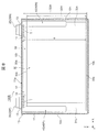
- FIG. 6 is a schematic cross-sectional view corresponding to FIG. 4 of the secondary battery 100A according to the second embodiment of the present disclosure.
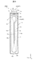
- FIG. 7 is a schematic cross-sectional view corresponding to FIG. 5 of the secondary battery 100A according to the second embodiment of the present disclosure.
- the secondary battery 100A of the present embodiment is different from the secondary battery 100 according to the first embodiment in that the end portion 50e of the insulating sheet 50 is fixed to the insulating plate 14 via the adhesive portion A. There is. Since the other points of the secondary battery 100A of the present embodiment are the same as those of the secondary battery 100 according to the first embodiment, the same reference numerals are given to the same parts and the description thereof will be omitted.
- the end portion 50e of the insulating sheet 50 is fixed to the insulating plate 14 via the adhesive portion A.
- the end portion 50e of the insulating sheet 50 adjacent to the battery lid 12 is prevented from being sandwiched between the battery lid 12 and the battery can 11. Can be done. Therefore, according to the present embodiment, it is possible to provide the secondary battery 100A capable of ensuring the airtightness of the battery container 10 more reliably than in the conventional case, as in the above-described first embodiment.
- the adhesive portion A is formed, for example, by applying an acrylic adhesive or an adhesive to at least one of the insulating sheet 50 and the insulating plate 14 and drying or curing between the insulating sheet 50 and the insulating plate 14. Can be done.
- a plurality of adhesive portions A may be arranged at intervals in the circumferential direction of the battery can 11 along the opening edge of the opening 11a of the battery can 11, but as shown in FIGS. 6 and 7, insulation is provided. It is preferable to arrange the adhesive portion A in a linear, strip-like, or planar shape along the side surface of the plate 14. As a result, the adhesive area by the adhesive portion A can be increased, and the end portion 50e of the insulating sheet 50 can be more firmly fixed to the insulating plate 14. Further, the adhesive portion A can be arbitrarily combined with two or more of the point-shaped, linear, strip-shaped, and planar arrangements.
- FIG. 8 is a schematic cross-sectional view corresponding to FIG. 4 of the secondary battery 100B according to the third embodiment of the present disclosure.
- FIG. 9 is a schematic cross-sectional view corresponding to FIG. 5 of the secondary battery 100B according to the third embodiment of the present disclosure.
- the secondary battery 100B of the present embodiment is different from the secondary battery 100 according to the first embodiment in that the end portion 50e of the insulating sheet 50 is fixed to the insulating plate 14 by the adhesive tape T. Since the other points of the secondary battery 100B of the present embodiment are the same as those of the secondary battery 100 according to the first embodiment, the same reference numerals are given to the same parts and the description thereof will be omitted.
- the end portion 50e of the insulating sheet 50 is fixed to the insulating plate 14 by the adhesive tape T.
- the end portion 50e of the insulating sheet 50 adjacent to the battery lid 12 is prevented from being sandwiched between the battery lid 12 and the battery can 11. Can be done. Therefore, according to the present embodiment, similarly to the above-described first embodiment, it is possible to provide the secondary battery 100B capable of ensuring the airtightness of the battery container 10 more reliably than before.
- the adhesive tape T for example, one having an acrylic adhesive layer on the surface of a resin base material such as polyethylene, polypropylene, or polyimide can be used.
- the adhesive tape T is attached to, for example, the side surface of the insulating plate 14 facing the wide side surface 10w of the battery container 10 and the side surface of the insulating plate 14 facing the narrow side surface 10n of the battery container 10.
- the adhesive tape T may be attached only to the side surface of the insulating plate 14 facing the narrow side surface 10n of the battery container 10, and may be attached only to the side surface of the insulating plate 14 facing the wide side surface 10w of the battery container 10. It may be worn.
- the end portion 50e of the insulating sheet 50 can be fixed to the insulating plate 14 without heating and pressurizing the insulating sheet 50 and the insulating plate 14. Further, by using the adhesive tape T, the step of applying the adhesive and the step of drying or curing the applied adhesive can be omitted. Therefore, the manufacturing process of the secondary battery 100 can be simplified and the productivity of the secondary battery 100 can be improved.
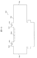
- FIG. 10 is a developed view of the insulating sheet 50C of the secondary battery 100C according to the fourth embodiment of the present disclosure.
- FIG. 11 is a schematic cross-sectional view corresponding to FIG. 5 of the secondary battery 100C according to the fourth embodiment of the present disclosure.
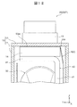
- FIG. 12 is an enlarged view of the vicinity of the insulating plate 14 of the secondary battery 100C shown in FIG.
- the end portion 50e of the insulating sheet 50C is sandwiched between the current collector plate 40 and the insulating plate 14 or between the battery lid 12 and the insulating plate 14 to form the insulating plate 14. It differs from the secondary battery 100 according to the first embodiment in that it is fixed. Since the other points of the secondary battery 100C of the present embodiment are the same as those of the secondary battery 100 according to the first embodiment, the same reference numerals are given to the same parts and the description thereof will be omitted.
- the end portion 50e of the insulating sheet 50C is sandwiched between the battery lid 12 and the insulating plate 14 and fixed to the insulating plate 14.
- the end portion 50e of the insulating sheet 50C may be sandwiched between the current collector plate 40 and the insulating plate 14 and fixed to the insulating plate 14.
- the insulating sheet 50C is provided with a pair of tab portions 50et at the end portion 50e adjacent to the battery lid 12, for example, as shown in FIG.
- the tab portion 50et is provided in a tab shape protruding from the other portion of the end portion 50e of the insulating sheet 50.
- the pair of tab portions 50et are provided at intervals corresponding to the pair of insulating plates 14.
- the width of the tab portion 50et in the protruding direction is approximately equal to, for example, the width of the insulating plate 14 in the thickness direction (Y direction) of the secondary battery 100C.
- the length of the tab portion 50et along the edge of the end portion 50e of the insulating sheet 50 is approximately equal to, for example, the length of the insulating plate 14 in the width direction (X direction) of the secondary battery 100C.
- the tab portion 50et has, for example, a through hole 50h through which the connection portion 22 of the external terminal 20 is inserted.
- the tab portion 50et may have a notch through which the connection portion 22 of the external terminal 20 is inserted instead of the through hole 50h.
- the tab portion 50et does not have to have a through hole 50h through which the connection portion 22 is inserted and a notch as long as the width in the protruding direction is narrow and does not interfere with the connection portion 22 of the external terminal 20.
- the end portion 50e of the insulating sheet 50 may have, for example, a concave notch portion 50ec between the pair of tab portions 50et.
- a concave notch portion 50ec between the pair of tab portions 50et.
Landscapes
- Chemical & Material Sciences (AREA)
- Chemical Kinetics & Catalysis (AREA)
- Electrochemistry (AREA)
- General Chemical & Material Sciences (AREA)
- Engineering & Computer Science (AREA)
- Manufacturing & Machinery (AREA)
- Connection Of Batteries Or Terminals (AREA)
- Secondary Cells (AREA)
- Sealing Battery Cases Or Jackets (AREA)
- Cell Separators (AREA)
Abstract
Description
図1は、本開示の実施形態1に係る二次電池100の斜視図である。図2は、図1に示す二次電池100の分解斜視図である。図3は、図2に示す二次電池100の捲回体30の分解斜視図である。図4は、図1に示す二次電池100のIV-IV線に沿う模式的な断面図である。図5は、図1に示す二次電池100のV-V線に沿う模式的な断面図である。なお、図4および図5では、二次電池100の各部と絶縁シート50との位置関係を明確にするために、絶縁シート50は破線で外形のみを示している。
次に、図1から図3を援用し、図6および図7を参照して、本開示の二次電池の実施形態2を説明する。図6は、本開示の実施形態2に係る二次電池100Aの図4に相当する模式的な断面図である。図7は、本開示の実施形態2に係る二次電池100Aの図5に相当する模式的な断面図である。
次に、図1から図3を援用し、図8および図9を参照して、本開示の二次電池の実施形態3を説明する。図8は、本開示の実施形態3に係る二次電池100Bの図4に相当する模式的な断面図である。図9は、本開示の実施形態3に係る二次電池100Bの図5に相当する模式的な断面図である。
次に、図1から図3を援用し、図10から図12を参照して、本開示の二次電池の実施形態4を説明する。図10は、本開示の実施形態4に係る二次電池100Cの絶縁シート50Cの展開図である。図11は、本開示の実施形態4に係る二次電池100Cの図5に相当する模式的な断面図である。図12は、図11に示す二次電池100Cの絶縁板14の近傍の拡大図である。
11a 開口部
12 電池蓋
14 絶縁板
20 外部端子
30 捲回体
31 正極電極
32 負極電極
33 セパレータ
34 セパレータ
40 集電板
50 絶縁シート
50e 端部
50s 端部
100 二次電池
100A 二次電池
100B 二次電池
100C 二次電池
A 接着部
T 粘着テープ
W 溶着部
Claims (9)
- 正極電極と負極電極とがセパレータが介在されて捲回された捲回体と、
前記正極電極と前記負極電極にそれぞれ接続された一対の集電板と、
前記捲回体および前記集電板を収容する電池缶と、
前記電池缶の開口部に接合された電池蓋と、
前記集電板と前記電池蓋との間に配置された絶縁板と、
前記電池缶の内部で前記捲回体および前記集電板を覆う絶縁シートと、
各々の前記集電板に接続されるとともに前記絶縁板および前記電池蓋を貫通して前記電池蓋の外側に露出した一対の外部端子と、を備え、
前記電池蓋に隣接する前記絶縁シートの端部が前記絶縁板に固定されていることを特徴とする二次電池。 - 前記電池蓋の一端と他端に離隔して配置された一対の前記絶縁板を備えることを特徴とする請求項1に記載の二次電池。
- 前記絶縁シートは、前記開口部の開口縁に沿う前記電池缶の周方向において、前記捲回体を覆うとともに、前記周方向の端部が一対の前記絶縁板と重ならない位置に配置されていることを特徴とする請求項2に記載の二次電池。
- 前記絶縁シートは、前記開口部の開口縁に沿う前記電池缶の周方向において、前記捲回体を全周に亘って覆うとともに、前記周方向の端部が重なり合っていることを特徴とする請求項1または請求項2に記載の二次電池。
- 前記絶縁シートは、複数の部分絶縁シートを有することを特徴とする請求項3または請求項4に記載の二次電池。
- 前記絶縁シートの前記端部は、溶着部を介して前記絶縁板に固定されていることを特徴とする請求項1に記載の二次電池。
- 前記絶縁シートの前記端部は、接着部を介して前記絶縁板に固定されていることを特徴とする請求項1に記載の二次電池。
- 前記絶縁シートの前記端部は、粘着テープによって前記絶縁板に固定されていることを特徴とする請求項1に記載の二次電池。
- 前記絶縁シートの前記端部は、前記集電板と前記絶縁板との間または前記電池蓋と前記絶縁板との間に挟まれていることを特徴とする請求項1に記載の二次電池。
Priority Applications (4)
| Application Number | Priority Date | Filing Date | Title |
|---|---|---|---|
| JP2021506154A JP7118242B2 (ja) | 2019-03-20 | 2019-12-05 | 二次電池 |
| US17/299,494 US12494511B2 (en) | 2019-03-20 | 2019-12-05 | Secondary battery |
| EP19919560.3A EP3944355A4 (en) | 2019-03-20 | 2019-12-05 | SECONDARY BATTERY |
| CN201980079452.4A CN113287222B (zh) | 2019-03-20 | 2019-12-05 | 二次电池 |
Applications Claiming Priority (2)
| Application Number | Priority Date | Filing Date | Title |
|---|---|---|---|
| JP2019-052050 | 2019-03-20 | ||
| JP2019052050 | 2019-03-20 |
Publications (1)
| Publication Number | Publication Date |
|---|---|
| WO2020188902A1 true WO2020188902A1 (ja) | 2020-09-24 |
Family
ID=72520604
Family Applications (1)
| Application Number | Title | Priority Date | Filing Date |
|---|---|---|---|
| PCT/JP2019/047576 Ceased WO2020188902A1 (ja) | 2019-03-20 | 2019-12-05 | 二次電池 |
Country Status (5)
| Country | Link |
|---|---|
| US (1) | US12494511B2 (ja) |
| EP (1) | EP3944355A4 (ja) |
| JP (1) | JP7118242B2 (ja) |
| CN (1) | CN113287222B (ja) |
| WO (1) | WO2020188902A1 (ja) |
Cited By (2)
| Publication number | Priority date | Publication date | Assignee | Title |
|---|---|---|---|---|
| JP2024109761A (ja) * | 2021-09-21 | 2024-08-14 | プライムプラネットエナジー&ソリューションズ株式会社 | 電池 |
| JP2024154921A (ja) * | 2023-04-20 | 2024-10-31 | プライムプラネットエナジー&ソリューションズ株式会社 | 蓄電デバイス |
Families Citing this family (7)
| Publication number | Priority date | Publication date | Assignee | Title |
|---|---|---|---|---|
| CN117063339A (zh) * | 2022-01-14 | 2023-11-14 | 宁德时代新能源科技股份有限公司 | 绝缘贴片、电池单体、电池及装置 |
| KR102649356B1 (ko) * | 2022-04-15 | 2024-03-19 | 주식회사 엘지에너지솔루션 | 안전성이 강화된 배터리 모듈 |
| EP4391189A4 (en) | 2022-04-15 | 2025-04-02 | LG Energy Solution, Ltd. | Battery module having enhanced safety |
| CN115133143A (zh) * | 2022-07-14 | 2022-09-30 | 安徽国洁新能源科技有限公司 | 基于四元体系的锂离子电芯的制造方法 |
| EP4645483A4 (en) * | 2022-12-26 | 2026-04-15 | Vehicle Energy Japan Inc | RECTANGULAR SECONDARY BATTERY |
| CN119366056A (zh) * | 2023-01-04 | 2025-01-24 | 宁德时代新能源科技股份有限公司 | 电池单体、电池及用电装置 |
| WO2026043191A1 (ko) * | 2024-08-19 | 2026-02-26 | 주식회사 엘지에너지솔루션 | 이차 전지 및 이차 전지의 제조 방법 |
Citations (7)
| Publication number | Priority date | Publication date | Assignee | Title |
|---|---|---|---|---|
| JP2015011895A (ja) * | 2013-06-28 | 2015-01-19 | 日立オートモティブシステムズ株式会社 | 角形二次電池 |
| JP2015041523A (ja) * | 2013-08-22 | 2015-03-02 | 株式会社豊田自動織機 | 蓄電装置及び蓄電装置の製造方法 |
| JP2015103277A (ja) | 2013-11-21 | 2015-06-04 | 日立オートモティブシステムズ株式会社 | 角形二次電池 |
| JP2015213042A (ja) * | 2014-05-07 | 2015-11-26 | 日立オートモティブシステムズ株式会社 | 二次電池 |
| WO2016088506A1 (ja) * | 2014-12-04 | 2016-06-09 | 日立オートモティブシステムズ株式会社 | 角形二次電池 |
| JP2016197555A (ja) * | 2015-04-03 | 2016-11-24 | トヨタ自動車株式会社 | 電池 |
| JP2018056085A (ja) * | 2016-09-30 | 2018-04-05 | 日立オートモティブシステムズ株式会社 | 二次電池 |
Family Cites Families (3)
| Publication number | Priority date | Publication date | Assignee | Title |
|---|---|---|---|---|
| CN103748733B (zh) * | 2011-08-25 | 2016-06-22 | 日立汽车系统株式会社 | 锂离子二次电池和其制造方法 |
| JP5336024B1 (ja) * | 2012-01-23 | 2013-11-06 | 日立ビークルエナジー株式会社 | 二次電池 |
| US20170250388A1 (en) * | 2014-09-03 | 2017-08-31 | Hitachi Automotive Systems, Ltd. | Prismatic secondary battery |
-
2019
- 2019-12-05 JP JP2021506154A patent/JP7118242B2/ja active Active
- 2019-12-05 US US17/299,494 patent/US12494511B2/en active Active
- 2019-12-05 CN CN201980079452.4A patent/CN113287222B/zh active Active
- 2019-12-05 EP EP19919560.3A patent/EP3944355A4/en active Pending
- 2019-12-05 WO PCT/JP2019/047576 patent/WO2020188902A1/ja not_active Ceased
Patent Citations (7)
| Publication number | Priority date | Publication date | Assignee | Title |
|---|---|---|---|---|
| JP2015011895A (ja) * | 2013-06-28 | 2015-01-19 | 日立オートモティブシステムズ株式会社 | 角形二次電池 |
| JP2015041523A (ja) * | 2013-08-22 | 2015-03-02 | 株式会社豊田自動織機 | 蓄電装置及び蓄電装置の製造方法 |
| JP2015103277A (ja) | 2013-11-21 | 2015-06-04 | 日立オートモティブシステムズ株式会社 | 角形二次電池 |
| JP2015213042A (ja) * | 2014-05-07 | 2015-11-26 | 日立オートモティブシステムズ株式会社 | 二次電池 |
| WO2016088506A1 (ja) * | 2014-12-04 | 2016-06-09 | 日立オートモティブシステムズ株式会社 | 角形二次電池 |
| JP2016197555A (ja) * | 2015-04-03 | 2016-11-24 | トヨタ自動車株式会社 | 電池 |
| JP2018056085A (ja) * | 2016-09-30 | 2018-04-05 | 日立オートモティブシステムズ株式会社 | 二次電池 |
Non-Patent Citations (1)
| Title |
|---|
| See also references of EP3944355A4 |
Cited By (4)
| Publication number | Priority date | Publication date | Assignee | Title |
|---|---|---|---|---|
| JP2024109761A (ja) * | 2021-09-21 | 2024-08-14 | プライムプラネットエナジー&ソリューションズ株式会社 | 電池 |
| JP7825664B2 (ja) | 2021-09-21 | 2026-03-06 | プライムプラネットエナジー&ソリューションズ株式会社 | 電池 |
| JP2024154921A (ja) * | 2023-04-20 | 2024-10-31 | プライムプラネットエナジー&ソリューションズ株式会社 | 蓄電デバイス |
| JP7738596B2 (ja) | 2023-04-20 | 2025-09-12 | プライムプラネットエナジー&ソリューションズ株式会社 | 蓄電デバイス |
Also Published As
| Publication number | Publication date |
|---|---|
| US20220085421A1 (en) | 2022-03-17 |
| US12494511B2 (en) | 2025-12-09 |
| JP7118242B2 (ja) | 2022-08-15 |
| CN113287222A (zh) | 2021-08-20 |
| JPWO2020188902A1 (ja) | 2021-10-21 |
| EP3944355A4 (en) | 2023-11-15 |
| EP3944355A1 (en) | 2022-01-26 |
| CN113287222B (zh) | 2024-03-19 |
Similar Documents
| Publication | Publication Date | Title |
|---|---|---|
| JP7118242B2 (ja) | 二次電池 | |
| CN105609693B (zh) | 电极组件以及具有该电极组件的电池包 | |
| US20170125778A1 (en) | Rectangular Secondary Battery | |
| CN104067411A (zh) | 二次电池 | |
| CN101405894A (zh) | 具有外膜罩的电子装置 | |
| CN106575721A (zh) | 方形二次电池 | |
| EP3121873A1 (en) | Secondary battery | |
| JP6270613B2 (ja) | 角形二次電池 | |
| JP6715936B2 (ja) | 角形二次電池 | |
| JP6530819B2 (ja) | 二次電池 | |
| JP6562726B2 (ja) | 角形二次電池及びその製造方法 | |
| JP6809860B2 (ja) | 二次電池 | |
| JP6235422B2 (ja) | 二次電池 | |
| JP7459029B2 (ja) | 電池および該電池の製造方法 | |
| JP7065965B2 (ja) | 二次電池 | |
| US20240380077A1 (en) | Secondary Battery | |
| CN116505149A (zh) | 二次电池及二次电池的制造方法 | |
| JP2019071259A (ja) | 蓄電素子、及び蓄電素子の製造方法 | |
| CN106469830A (zh) | 二次电池及其制造方法 | |
| JP2016081751A (ja) | 角形二次電池 | |
| WO2016076108A1 (ja) | 角形二次電池 | |
| JP6360305B2 (ja) | 角形二次電池 | |
| JP7393586B2 (ja) | 角型二次電池及びその製造方法 | |
| JP2015204236A (ja) | 二次電池および電池モジュール | |
| JP6892338B2 (ja) | 蓄電装置および蓄電装置の製造方法 |
Legal Events
| Date | Code | Title | Description |
|---|---|---|---|
| 121 | Ep: the epo has been informed by wipo that ep was designated in this application |
Ref document number: 19919560 Country of ref document: EP Kind code of ref document: A1 |
|
| ENP | Entry into the national phase |
Ref document number: 2021506154 Country of ref document: JP Kind code of ref document: A |
|
| NENP | Non-entry into the national phase |
Ref country code: DE |
|
| ENP | Entry into the national phase |
Ref document number: 2019919560 Country of ref document: EP Effective date: 20211020 |
|
| WWG | Wipo information: grant in national office |
Ref document number: 17299494 Country of ref document: US |