WO2020189565A1 - Dispositif d'apprentissage automatique et dispositif de palier magnétique - Google Patents
Dispositif d'apprentissage automatique et dispositif de palier magnétique Download PDFInfo
- Publication number
- WO2020189565A1 WO2020189565A1 PCT/JP2020/011162 JP2020011162W WO2020189565A1 WO 2020189565 A1 WO2020189565 A1 WO 2020189565A1 JP 2020011162 W JP2020011162 W JP 2020011162W WO 2020189565 A1 WO2020189565 A1 WO 2020189565A1
- Authority
- WO
- WIPO (PCT)
- Prior art keywords
- shaft
- unit
- value
- learning
- parameter
- Prior art date
- Legal status (The legal status is an assumption and is not a legal conclusion. Google has not performed a legal analysis and makes no representation as to the accuracy of the status listed.)
- Ceased
Links
Images









Classifications
-
- F—MECHANICAL ENGINEERING; LIGHTING; HEATING; WEAPONS; BLASTING
- F16—ENGINEERING ELEMENTS AND UNITS; GENERAL MEASURES FOR PRODUCING AND MAINTAINING EFFECTIVE FUNCTIONING OF MACHINES OR INSTALLATIONS; THERMAL INSULATION IN GENERAL
- F16C—SHAFTS; FLEXIBLE SHAFTS; ELEMENTS OR CRANKSHAFT MECHANISMS; ROTARY BODIES OTHER THAN GEARING ELEMENTS; BEARINGS
- F16C32/00—Bearings not otherwise provided for
- F16C32/04—Bearings not otherwise provided for using magnetic or electric supporting means
- F16C32/0406—Magnetic bearings
-
- F—MECHANICAL ENGINEERING; LIGHTING; HEATING; WEAPONS; BLASTING
- F04—POSITIVE - DISPLACEMENT MACHINES FOR LIQUIDS; PUMPS FOR LIQUIDS OR ELASTIC FLUIDS
- F04D—NON-POSITIVE-DISPLACEMENT PUMPS
- F04D17/00—Radial-flow pumps, e.g. centrifugal pumps; Helico-centrifugal pumps
- F04D17/08—Centrifugal pumps
- F04D17/10—Centrifugal pumps for compressing or evacuating
-
- F—MECHANICAL ENGINEERING; LIGHTING; HEATING; WEAPONS; BLASTING
- F04—POSITIVE - DISPLACEMENT MACHINES FOR LIQUIDS; PUMPS FOR LIQUIDS OR ELASTIC FLUIDS
- F04D—NON-POSITIVE-DISPLACEMENT PUMPS
- F04D25/00—Pumping installations or systems
- F04D25/02—Units comprising pumps and their driving means
- F04D25/06—Units comprising pumps and their driving means the pump being electrically driven
-
- F—MECHANICAL ENGINEERING; LIGHTING; HEATING; WEAPONS; BLASTING
- F04—POSITIVE - DISPLACEMENT MACHINES FOR LIQUIDS; PUMPS FOR LIQUIDS OR ELASTIC FLUIDS
- F04D—NON-POSITIVE-DISPLACEMENT PUMPS
- F04D27/00—Control, e.g. regulation, of pumps, pumping installations or pumping systems specially adapted for elastic fluids
- F04D27/001—Testing thereof; Determination or simulation of flow characteristics; Stall or surge detection, e.g. condition monitoring
-
- F—MECHANICAL ENGINEERING; LIGHTING; HEATING; WEAPONS; BLASTING
- F04—POSITIVE - DISPLACEMENT MACHINES FOR LIQUIDS; PUMPS FOR LIQUIDS OR ELASTIC FLUIDS
- F04D—NON-POSITIVE-DISPLACEMENT PUMPS
- F04D29/00—Details, component parts, or accessories
- F04D29/05—Shafts or bearings, or assemblies thereof, specially adapted for elastic fluid pumps
- F04D29/051—Axial thrust balancing
- F04D29/0513—Axial thrust balancing hydrostatic; hydrodynamic thrust bearings
-
- F—MECHANICAL ENGINEERING; LIGHTING; HEATING; WEAPONS; BLASTING
- F04—POSITIVE - DISPLACEMENT MACHINES FOR LIQUIDS; PUMPS FOR LIQUIDS OR ELASTIC FLUIDS
- F04D—NON-POSITIVE-DISPLACEMENT PUMPS
- F04D29/00—Details, component parts, or accessories
- F04D29/05—Shafts or bearings, or assemblies thereof, specially adapted for elastic fluid pumps
- F04D29/056—Bearings
- F04D29/058—Bearings magnetic; electromagnetic
-
- F—MECHANICAL ENGINEERING; LIGHTING; HEATING; WEAPONS; BLASTING
- F16—ENGINEERING ELEMENTS AND UNITS; GENERAL MEASURES FOR PRODUCING AND MAINTAINING EFFECTIVE FUNCTIONING OF MACHINES OR INSTALLATIONS; THERMAL INSULATION IN GENERAL
- F16C—SHAFTS; FLEXIBLE SHAFTS; ELEMENTS OR CRANKSHAFT MECHANISMS; ROTARY BODIES OTHER THAN GEARING ELEMENTS; BEARINGS
- F16C32/00—Bearings not otherwise provided for
- F16C32/04—Bearings not otherwise provided for using magnetic or electric supporting means
- F16C32/0406—Magnetic bearings
- F16C32/044—Active magnetic bearings
- F16C32/0444—Details of devices to control the actuation of the electromagnets
- F16C32/0446—Determination of the actual position of the moving member, e.g. details of sensors
-
- F—MECHANICAL ENGINEERING; LIGHTING; HEATING; WEAPONS; BLASTING
- F16—ENGINEERING ELEMENTS AND UNITS; GENERAL MEASURES FOR PRODUCING AND MAINTAINING EFFECTIVE FUNCTIONING OF MACHINES OR INSTALLATIONS; THERMAL INSULATION IN GENERAL
- F16C—SHAFTS; FLEXIBLE SHAFTS; ELEMENTS OR CRANKSHAFT MECHANISMS; ROTARY BODIES OTHER THAN GEARING ELEMENTS; BEARINGS
- F16C32/00—Bearings not otherwise provided for
- F16C32/04—Bearings not otherwise provided for using magnetic or electric supporting means
- F16C32/0406—Magnetic bearings
- F16C32/044—Active magnetic bearings
- F16C32/0444—Details of devices to control the actuation of the electromagnets
- F16C32/0451—Details of controllers, i.e. the units determining the power to be supplied, e.g. comparing elements, feedback arrangements with P.I.D. control
-
- F—MECHANICAL ENGINEERING; LIGHTING; HEATING; WEAPONS; BLASTING
- F16—ENGINEERING ELEMENTS AND UNITS; GENERAL MEASURES FOR PRODUCING AND MAINTAINING EFFECTIVE FUNCTIONING OF MACHINES OR INSTALLATIONS; THERMAL INSULATION IN GENERAL
- F16C—SHAFTS; FLEXIBLE SHAFTS; ELEMENTS OR CRANKSHAFT MECHANISMS; ROTARY BODIES OTHER THAN GEARING ELEMENTS; BEARINGS
- F16C32/00—Bearings not otherwise provided for
- F16C32/04—Bearings not otherwise provided for using magnetic or electric supporting means
- F16C32/0406—Magnetic bearings
- F16C32/044—Active magnetic bearings
- F16C32/0444—Details of devices to control the actuation of the electromagnets
- F16C32/0451—Details of controllers, i.e. the units determining the power to be supplied, e.g. comparing elements, feedback arrangements with P.I.D. control
- F16C32/0453—Details of controllers, i.e. the units determining the power to be supplied, e.g. comparing elements, feedback arrangements with P.I.D. control for controlling two axes, i.e. combined control of x-axis and y-axis
-
- F—MECHANICAL ENGINEERING; LIGHTING; HEATING; WEAPONS; BLASTING
- F16—ENGINEERING ELEMENTS AND UNITS; GENERAL MEASURES FOR PRODUCING AND MAINTAINING EFFECTIVE FUNCTIONING OF MACHINES OR INSTALLATIONS; THERMAL INSULATION IN GENERAL
- F16C—SHAFTS; FLEXIBLE SHAFTS; ELEMENTS OR CRANKSHAFT MECHANISMS; ROTARY BODIES OTHER THAN GEARING ELEMENTS; BEARINGS
- F16C32/00—Bearings not otherwise provided for
- F16C32/04—Bearings not otherwise provided for using magnetic or electric supporting means
- F16C32/0406—Magnetic bearings
- F16C32/044—Active magnetic bearings
- F16C32/0444—Details of devices to control the actuation of the electromagnets
- F16C32/0457—Details of the power supply to the electromagnets
-
- F—MECHANICAL ENGINEERING; LIGHTING; HEATING; WEAPONS; BLASTING
- F16—ENGINEERING ELEMENTS AND UNITS; GENERAL MEASURES FOR PRODUCING AND MAINTAINING EFFECTIVE FUNCTIONING OF MACHINES OR INSTALLATIONS; THERMAL INSULATION IN GENERAL
- F16C—SHAFTS; FLEXIBLE SHAFTS; ELEMENTS OR CRANKSHAFT MECHANISMS; ROTARY BODIES OTHER THAN GEARING ELEMENTS; BEARINGS
- F16C41/00—Other accessories, e.g. devices integrated in the bearing not relating to the bearing function as such
-
- G—PHYSICS
- G06—COMPUTING OR CALCULATING; COUNTING
- G06N—COMPUTING ARRANGEMENTS BASED ON SPECIFIC COMPUTATIONAL MODELS
- G06N20/00—Machine learning
- G06N20/10—Machine learning using kernel methods, e.g. support vector machines [SVM]
-
- G—PHYSICS
- G06—COMPUTING OR CALCULATING; COUNTING
- G06N—COMPUTING ARRANGEMENTS BASED ON SPECIFIC COMPUTATIONAL MODELS
- G06N20/00—Machine learning
- G06N20/20—Ensemble learning
-
- G—PHYSICS
- G06—COMPUTING OR CALCULATING; COUNTING
- G06N—COMPUTING ARRANGEMENTS BASED ON SPECIFIC COMPUTATIONAL MODELS
- G06N3/00—Computing arrangements based on biological models
- G06N3/02—Neural networks
- G06N3/04—Architecture, e.g. interconnection topology
- G06N3/0464—Convolutional networks [CNN, ConvNet]
-
- G—PHYSICS
- G06—COMPUTING OR CALCULATING; COUNTING
- G06N—COMPUTING ARRANGEMENTS BASED ON SPECIFIC COMPUTATIONAL MODELS
- G06N3/00—Computing arrangements based on biological models
- G06N3/02—Neural networks
- G06N3/08—Learning methods
- G06N3/084—Backpropagation, e.g. using gradient descent
-
- G—PHYSICS
- G06—COMPUTING OR CALCULATING; COUNTING
- G06N—COMPUTING ARRANGEMENTS BASED ON SPECIFIC COMPUTATIONAL MODELS
- G06N3/00—Computing arrangements based on biological models
- G06N3/02—Neural networks
- G06N3/08—Learning methods
- G06N3/0895—Weakly supervised learning, e.g. semi-supervised or self-supervised learning
-
- G—PHYSICS
- G06—COMPUTING OR CALCULATING; COUNTING
- G06N—COMPUTING ARRANGEMENTS BASED ON SPECIFIC COMPUTATIONAL MODELS
- G06N3/00—Computing arrangements based on biological models
- G06N3/02—Neural networks
- G06N3/08—Learning methods
- G06N3/09—Supervised learning
-
- G—PHYSICS
- G06—COMPUTING OR CALCULATING; COUNTING
- G06N—COMPUTING ARRANGEMENTS BASED ON SPECIFIC COMPUTATIONAL MODELS
- G06N3/00—Computing arrangements based on biological models
- G06N3/02—Neural networks
- G06N3/08—Learning methods
- G06N3/092—Reinforcement learning
-
- G—PHYSICS
- G06—COMPUTING OR CALCULATING; COUNTING
- G06N—COMPUTING ARRANGEMENTS BASED ON SPECIFIC COMPUTATIONAL MODELS
- G06N3/00—Computing arrangements based on biological models
- G06N3/02—Neural networks
- G06N3/08—Learning methods
- G06N3/096—Transfer learning
-
- G—PHYSICS
- G06—COMPUTING OR CALCULATING; COUNTING
- G06N—COMPUTING ARRANGEMENTS BASED ON SPECIFIC COMPUTATIONAL MODELS
- G06N5/00—Computing arrangements using knowledge-based models
- G06N5/01—Dynamic search techniques; Heuristics; Dynamic trees; Branch-and-bound
-
- F—MECHANICAL ENGINEERING; LIGHTING; HEATING; WEAPONS; BLASTING
- F16—ENGINEERING ELEMENTS AND UNITS; GENERAL MEASURES FOR PRODUCING AND MAINTAINING EFFECTIVE FUNCTIONING OF MACHINES OR INSTALLATIONS; THERMAL INSULATION IN GENERAL
- F16C—SHAFTS; FLEXIBLE SHAFTS; ELEMENTS OR CRANKSHAFT MECHANISMS; ROTARY BODIES OTHER THAN GEARING ELEMENTS; BEARINGS
- F16C32/00—Bearings not otherwise provided for
- F16C32/04—Bearings not otherwise provided for using magnetic or electric supporting means
- F16C32/0406—Magnetic bearings
- F16C32/044—Active magnetic bearings
- F16C32/0459—Details of the magnetic circuit
- F16C32/0468—Details of the magnetic circuit of moving parts of the magnetic circuit, e.g. of the rotor
-
- F—MECHANICAL ENGINEERING; LIGHTING; HEATING; WEAPONS; BLASTING
- F16—ENGINEERING ELEMENTS AND UNITS; GENERAL MEASURES FOR PRODUCING AND MAINTAINING EFFECTIVE FUNCTIONING OF MACHINES OR INSTALLATIONS; THERMAL INSULATION IN GENERAL
- F16C—SHAFTS; FLEXIBLE SHAFTS; ELEMENTS OR CRANKSHAFT MECHANISMS; ROTARY BODIES OTHER THAN GEARING ELEMENTS; BEARINGS
- F16C32/00—Bearings not otherwise provided for
- F16C32/04—Bearings not otherwise provided for using magnetic or electric supporting means
- F16C32/0406—Magnetic bearings
- F16C32/044—Active magnetic bearings
- F16C32/047—Details of housings; Mounting of active magnetic bearings
-
- G—PHYSICS
- G06—COMPUTING OR CALCULATING; COUNTING
- G06N—COMPUTING ARRANGEMENTS BASED ON SPECIFIC COMPUTATIONAL MODELS
- G06N3/00—Computing arrangements based on biological models
- G06N3/02—Neural networks
- G06N3/04—Architecture, e.g. interconnection topology
- G06N3/044—Recurrent networks, e.g. Hopfield networks
-
- G—PHYSICS
- G06—COMPUTING OR CALCULATING; COUNTING
- G06N—COMPUTING ARRANGEMENTS BASED ON SPECIFIC COMPUTATIONAL MODELS
- G06N3/00—Computing arrangements based on biological models
- G06N3/02—Neural networks
- G06N3/04—Architecture, e.g. interconnection topology
- G06N3/045—Combinations of networks
-
- G—PHYSICS
- G06—COMPUTING OR CALCULATING; COUNTING
- G06N—COMPUTING ARRANGEMENTS BASED ON SPECIFIC COMPUTATIONAL MODELS
- G06N3/00—Computing arrangements based on biological models
- G06N3/02—Neural networks
- G06N3/04—Architecture, e.g. interconnection topology
- G06N3/048—Activation functions
Definitions
- Patent Document 1 (Actual Kaihei 04-040308), the position of the supported body is detected by a sensor, and the electromagnetic force of the electromagnet is controlled based on the detection signal to hold the position of the supported body at a predetermined position.
- the configuration to be used is disclosed.
- the machine learning device of the first viewpoint learns the control conditions of the magnetic bearing device.
- the magnetic bearing device includes a magnetic bearing having a plurality of electromagnets that apply electromagnetic force to the shaft.
- the machine learning device includes a learning unit, a state variable acquisition unit, an evaluation data acquisition unit, and an update unit.
- the state variable acquisition unit acquires a state variable including at least one parameter that correlates with the position of the shaft.
- the evaluation data acquisition unit acquires evaluation data including at least one of the measured value of the shaft position, the target value of the shaft position, and the parameter correlating with the deviation from the target value.
- the update unit updates the learning state of the learning unit using the evaluation data.
- the learning unit learns the control conditions according to the output of the update unit.
- the machine learning device of the second viewpoint is the machine learning device of the first viewpoint, and the state variable includes at least the output value of the displacement sensor that outputs a signal according to the position of the shaft.
- the learning unit learns at least one of the voltage value of the electromagnet and the current value of the electromagnet as control conditions.
- the machine learning device of the third viewpoint is the machine learning device of the first viewpoint, and the state variables include at least the current value and voltage value of the electromagnet, or the current value and magnetic flux of the electromagnet.
- the learning unit learns at least one of the voltage value of the electromagnet and the current value of the electromagnet as control conditions.
- the machine learning device of the fourth viewpoint is the machine learning device of the first viewpoint, and the state variable includes at least the output value of the displacement sensor that outputs a signal according to the position of the shaft.
- the evaluation data includes at least the true value of the shaft position.
- the learning unit learns the position of the shaft as a control condition.
- the machine learning device of the fifth viewpoint is the machine learning device of the first viewpoint, and the state variables include at least the current value and voltage value of the electromagnet, or the current value and magnetic flux of the electromagnet.
- the evaluation data includes at least the true value of the shaft position.
- the learning unit learns the position of the shaft as a control condition.
- the machine learning device of the sixth viewpoint is the machine learning device of the first viewpoint, and the state variable includes at least the detected value of the shaft position and the command value of the shaft position.
- the learning unit learns at least one of the voltage value of the electromagnet and the current value of the electromagnet as control conditions.
- the machine learning device of the seventh aspect is the machine learning device of the second or third aspect, and the updating unit further increases the learning unit so that the current value for driving the magnetic bearing is equal to or less than a predetermined allowable value. Let them learn.
- the machine learning device of the eighth viewpoint is the machine learning device of the second or third viewpoint, and the evaluation data further includes a parameter correlating with the temperature of the inverter that drives the magnetic bearing.
- the update unit further learns the learning unit so that the temperature of the inverter becomes equal to or lower than a predetermined allowable value.
- the machine learning device of the ninth aspect is any one of the second, third and sixth aspects, and the state variable is the current of the electromagnet when the magnetic bearing is driven by the voltage type inverter.
- the detected value is further included, and when the magnetic bearing is driven by the current type inverter, the voltage detected value of the electromagnet is further included.
- the machine learning device of the tenth viewpoint is the machine learning device of the ninth viewpoint, and the updating unit further learns the learning unit in order to reduce the value that correlates with the responsiveness of the control of the current value.
- the machine learning device of the eleventh viewpoint is any one of the second, third, and sixth viewpoints, and the state variable further includes the rotation speed of the shaft.
- the machine learning device of the twelfth viewpoint is any one of the second, third, and sixth viewpoints, and the state variable further includes at least one parameter that correlates with the operating conditions of the refrigerating device.
- the freezing device includes a refrigerant circuit in which a compressor driven by an electric motor, a condenser, an expansion mechanism, and an evaporator are connected.
- the operating conditions include the range of the freezing capacity of the refrigerating apparatus and the range of the temperature of the medium that exchanges heat with the refrigerant circulating in the refrigerant circuit and flows into the condenser.
- the machine learning device of the thirteenth viewpoint is the machine learning device of the twelfth viewpoint, and the state variable further includes at least one parameter that correlates with the electromagnetic force applied to the shaft.
- the parameter that correlates with the electromagnetic force includes at least one of the parameter that correlates with the refrigerant load of the refrigerating device and the parameter that correlates with the physical property of the refrigerating device.
- the machine learning device of the 14th viewpoint is the machine learning device of the 12th viewpoint, and the state variable further includes at least one parameter that correlates with the characteristics of the magnetic bearing.
- the parameters that correlate with the characteristics of the magnetic bearing include at least one of the parameters that correlate with the inductance of the coil of the electromagnet and the parameters that correlate with the resistance of the coil of the electromagnet.
- the machine learning device of the fifteenth viewpoint is a machine learning device of the second or third viewpoint, and the evaluation data further includes a parameter correlating with the power consumption of the magnetic bearing.
- the update unit further learns the learning unit in order to reduce the power consumption.
- Parameters that correlate with power consumption include at least two of the current value for driving the magnetic bearing, the voltage value for driving the magnetic bearing, and the resistance of the coil of the electromagnet.
- the machine learning device of the 16th viewpoint is any one of the 7th, 8th and 15th viewpoints, and the state variable further includes at least one parameter that correlates with the operating conditions of the refrigerating device.
- the freezing device includes a refrigerant circuit in which a compressor driven by an electric motor, a condenser, an expansion mechanism, and an evaporator are connected.
- the operating conditions include the range of the freezing capacity of the refrigerating apparatus and the range of the temperature of the medium that exchanges heat with the refrigerant circulating in the refrigerant circuit and flows into the condenser.
- the machine learning device of the 17th viewpoint is any one of the 2nd, 3rd and 6th viewpoints, and the evaluation data correlates with the input energy supplied to the compressor driven by the electric motor. It further includes at least one parameter.
- the update unit further learns the learning unit in order to reduce the input energy.
- the machine learning device of the 18th viewpoint is the machine learning device of the 17th viewpoint, and the state variable correlates with at least one parameter that correlates with the operating conditions of the refrigerating device and the heat insulation efficiency of the impeller connected to the shaft. Further includes at least one of at least one parameter to be used.
- the freezing device includes a refrigerant circuit in which a compressor driven by an electric motor, a condenser, an expansion mechanism, and an evaporator are connected.
- the operating conditions include the range of the freezing capacity of the refrigerating apparatus and the range of the temperature of the medium that exchanges heat with the refrigerant circulating in the refrigerant circuit and flows into the condenser.
- the parameters that correlate with the adiabatic efficiency of the impeller include at least one of the parameters that correlate with the pressure of the refrigerant and the parameters that correlate with the temperature of the refrigerant.
- the machine learning device of the 19th viewpoint is the machine learning device of the 2nd or 4th viewpoint, and the state variable further includes a parameter correlating with the temperature of the displacement sensor.
- the machine learning device of the 20th viewpoint is any one of the machine learning devices of the 1st to 19th viewpoints, and the update unit calculates the reward based on the evaluation data.
- the learning department learns using rewards.
- the machine learning device of the 21st viewpoint is any one of the 1st to 19th viewpoints, and the learning unit changes the parameters of the function a plurality of times according to the output of the update unit, and the parameters are changed.
- the control condition is output from the state variable for each function.
- the update unit includes a storage unit and a determination unit.
- the determination unit determines the evaluation data and outputs the determination result.
- the storage unit creates and stores teacher data from state variables and evaluation data based on the determination result.
- the learning unit learns based on the teacher data accumulated in the storage unit.
- the machine learning device of the 22nd viewpoint is any one of the 1st to 21st viewpoints, and outputs control conditions based on the learned model obtained as a result of learning by the learning unit.
- the magnetic bearing device of the 23rd viewpoint includes a machine learning device of the 22nd viewpoint.
- FIG. 5 is an overall configuration diagram of an air conditioner 100 including the magnetic bearing device 10 according to the first embodiment. It is a vertical sectional view of a compressor 110. It is a cross-sectional view of a radial magnetic bearing 21. It is a vertical sectional view of a radial magnetic bearing 21. It is a top view of the thrust magnetic bearing 22. It is a vertical sectional view of a thrust magnetic bearing 22. It is a reference diagram for comparison, and is the block block diagram of the position control system of a shaft 115. It is a block block diagram of the position control system of a shaft 115 in 1st Embodiment. It is a block block diagram of the control unit 40 which performs supervised learning.
- FIG. 1 is an overall configuration diagram of the air conditioner 100.
- the air conditioner 100 includes a refrigerant circuit 190.
- the refrigerant circuit 190 is a closed circuit filled with a refrigerant.
- the refrigerant circuit 190 is provided with a compressor 110, a condenser 120, an expansion valve 130, an evaporator 140, and an electric motor cooling control device 150.
- Various compressors can be adopted as the compressor 110.
- the compressor 110 is a turbo compressor.
- the compressor 110 is driven by an electric motor 114. Electric power is supplied to the electric motor 114 from the electric motor control device 160.
- the condenser 120 and the evaporator 140 are water refrigerant heat exchangers.
- the expansion valve 130 is, for example, an electronic expansion valve.
- the refrigerant circuit 190 is provided with a sensor for detecting the refrigerant pressure, a sensor for detecting the refrigerant temperature, and the like.
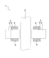
- FIG. 2 is a vertical sectional view of the compressor 110.
- the compressor 110 mainly includes a casing 112, a compression mechanism 113, an electric motor 114, a shaft 115, a radial touchdown bearing 116, a thrust touchdown bearing 117, and a magnetic bearing device 10.
- the casing 112 has a cylindrical shape with both ends closed.
- the casing 112 is arranged so that its cylindrical cylindrical axis is parallel in the horizontal direction.
- the space inside the casing 112 is partitioned by the wall portion 112a.
- the space on the right side of the wall portion 112a is the compression mechanism chamber S1 that houses the compression mechanism 113.
- the space on the left side of the wall portion 112a is the electric motor chamber S2 that houses the electric motor 114.
- a shaft 115 extending in the horizontal direction is arranged in the space inside the casing 112. The shaft 115 connects the compression mechanism 113 and the electric motor 114.
- the compression mechanism 113 compresses the fluid.
- the fluid is the refrigerant filled in the refrigerant circuit 190 in the present embodiment.
- the compression mechanism 113 mainly includes an impeller 113a and an inlet guide vane 113b.
- the impeller 113a is configured so that the outer shape is substantially conical with a plurality of blades.
- the impeller 113a is fixed to one end of the shaft 115.
- the inlet guide vane 113b is provided at the fluid suction port of the compression mechanism 113.
- the inlet guide vane 113b is a valve for controlling the suction amount of the fluid.
- the electric motor 114 rotates and drives the shaft 115.
- the electric motor 114 mainly has a stator 114a and a rotor 114b.
- the stator 114a is formed in a cylindrical shape and is fixed in the casing 112.
- the rotor 114b is formed in a cylindrical shape and is rotatably installed inside the stator 114a.
- a shaft hole for fixing the shaft 115 is formed in the center of the rotor 114b.
- a disk portion 115a is fixed to the end portion of the shaft 115.
- the disk portion 115a is fixed to the end portion to which the impeller 113a is not fixed.
- the electric motor control device 160 controls the electric power supplied to the electric motor 114 to start, stop, and control the rotation speed of the electric motor 114.
- the electric motor control device 160 mainly includes a converter circuit, an inverter circuit, and a microcomputer. These are mounted on the control board 160a.
- the microcomputer controls the switching operation of the switching element of the inverter circuit. Therefore, information such as the rotation speed of the electric motor 114 and the current value of the electric motor 114 is input to the microcomputer.
- the control board 160a is provided with a temperature sensor for the purpose of protecting the switching element and the like.
- the microcomputer uses the detected value of the temperature sensor when controlling the inverter circuit.
- the compressor 110 cools the electric motor 114 by flowing the refrigerant in the condenser 120 into the electric motor 114.
- the electric motor cooling control device 150 includes an electric on-off valve 150a and a temperature sensor 150b.
- the electric motor cooling control device 150 controls the on-off valve 150a according to the detected value of the temperature sensor 150b, and controls the flow rate of the refrigerant flowing from the condenser 120 into the electric motor 114.
- the temperature of the electric motor 114 can be maintained within a predetermined temperature range.
- the electric motor 114 is connected to the condenser 120 by piping via an on-off valve 150a.
- the electric motor 114 is also connected to the evaporator 140 by piping.
- the refrigerant that has flowed through the electric motor 114 and cooled the electric motor 114 is returned to the evaporator 140.
- the temperature sensor 150b is attached to a pipe connecting the electric motor 114 and the evaporator 140.
- the compressor 110 has two types of touchdown bearings, a radial touchdown bearing 116 and a thrust touchdown bearing 117.
- the radial touchdown bearing 116 supports the shaft 115 when the magnetic bearing device 10 is de-energized, in other words, when the shaft 115 is not magnetically levitated.
- the magnetic bearing device 10 magnetically levitates the shaft 115, which is a supported body, to rotatably support the shaft 115 in a non-contact manner.
- the magnetic bearing device 10 mainly includes one or more (three in this embodiment) magnetic bearings 21 and 22, one or more (five in this embodiment) displacement sensors 31 and 32, and a control unit. 40 and.
- Magnetic bearings 21 and 22 The magnetic bearings 21 and 22 have a pair of electromagnets facing each other with the supported body in between.
- the magnetic bearings 21 and 22 are configured to non-contactly support the supported body by the combined electromagnetic force of the electromagnet pair.
- the combined electromagnetic force of the electromagnet pair can be controlled by controlling the current flowing through the electromagnet pair, and the position of the supported body in the direction opposite to the electromagnet pair can be controlled.
- the magnetic bearing device 10 includes two radial magnetic bearings 21 and one thrust magnetic bearing 22 as magnetic bearings 21 and 22.
- FIG. 3 is a cross-sectional view of the radial magnetic bearing 21.
- FIG. 4 is a vertical cross-sectional view of the radial magnetic bearing 21.
- the radial magnetic bearing 21 has first to fourth electromagnets 51 to 54, and constitutes a heteropolar type radial magnetic bearing.
- the first and second electromagnets 51 and 52 face each other with the shaft 115 in between, and the shaft 115 is non-contactly supported by the electromagnetic forces F1 and F2 of the first and second electromagnets 51 and 52.
- the third and fourth electromagnets 53 and 54 face each other with the shaft 115 interposed therebetween, and the shaft 115 is non-contactly supported by the electromagnetic forces F3 and F4 of the third and fourth electromagnets 53 and 54.
- the facing directions of the third and fourth electromagnets 53 and 54 are orthogonal to the facing directions of the first and second electromagnets 51 and 52 in a plan view.
- the radial magnetic bearing 21 includes a magnetic bearing core 61 and eight coils 65.
- the magnetic bearing core 61 is formed by laminating a plurality of electromagnetic steel plates, for example, and has a back yoke 62 and eight teeth 63.
- the back yoke 62 is formed in a cylindrical shape.
- the eight teeth 63 are arranged in the circumferential direction at predetermined intervals (45 ° intervals in this embodiment) along the inner peripheral surface of the back yoke 62.
- the teeth 63 project radially inward from the inner peripheral surface of the back yoke 62.
- the inner peripheral surface (protruding end surface) of the teeth 63 faces the outer peripheral surface of the shaft 115 with a predetermined gap.
- the eight coils 65 are each wound around the eight teeth 63 of the magnetic bearing core 61.
- eight electromagnet portions 71 to 78 are formed.
- the first electromagnet unit 71, the second electromagnet unit 72, the seventh electromagnet unit 77, the eighth electromagnet unit 78, the third electromagnet unit 73, the fourth electromagnet unit 74, the fifth electromagnet unit 75, and the sixth electromagnet unit 76 are arranged in order in the clockwise direction.
- the first electromagnet 51 has a first electromagnet portion 71 and a second electromagnet portion 72.
- the second electromagnet 52 has a third electromagnet portion 73 and a fourth electromagnet portion 74.
- the third electromagnet 53 has a fifth electromagnet section 75 and a sixth electromagnet section 76.
- the fourth electromagnet 54 has a seventh electromagnet section 77 and an eighth electromagnet section 78.
- the winding direction of the coil 65 and the direction of the current flowing through the coil 65 are set so that attractive force is generated in each of the first to fourth electromagnets 51 to 54.
- the attractive force is an electromagnetic force acting in the direction of attracting the shaft 115.
- the winding direction of the coil 65 and the direction of the current flowing through the coil 65 are set so that the magnetic flux is generated in the direction of the loop-shaped arrow shown in FIG.
- FIG. 5 is a plan view of the thrust magnetic bearing 22.
- FIG. 6 is a vertical cross-sectional view of the thrust magnetic bearing 22.
- the thrust magnetic bearing 22 has first and second electromagnets 51 and 52.
- the first and second electromagnets 51 and 52 face each other with the disc portion 115a sandwiched in the horizontal direction, and the disc portions 115a are non-contactly supported by the electromagnetic forces F1 and F2 of the first and second electromagnets 51 and 52.
- the thrust magnetic bearing 22 includes two magnetic bearing cores 61 and two coils 65.
- Each of the two magnetic bearing cores 61 is formed in an annular shape, and is arranged on both sides of the disk portion 115a in the axial direction with a predetermined gap.
- Circumferential grooves are formed on the facing surface of the magnetic bearing core 61 over the entire circumference.
- the two coils 65 are housed in the circumferential grooves of the two magnetic bearing cores 61, respectively.
- the first and second electromagnets 51 and 52 are configured.
- the first and second electromagnets are controlled.
- the position of the disk portion 115a (position of the shaft 115) in the opposite direction (horizontal direction) of the electromagnets 51 and 52 can be controlled.
- the winding direction of the coil 65 and the direction of the current flowing through the coil 65 are set so that attractive force is generated in each of the first and second electromagnets 51 and 52.
- the attractive force is an electromagnetic force acting in the direction of attracting the disk portion 115a.
- the winding direction of the coil 65 and the direction of the current flowing through the coil 65 are set so that the magnetic flux is generated in the direction of the loop-shaped arrow shown in FIG.
- the displacement sensors 31 and 32 are both eddy current type displacement sensors.
- the displacement sensors 31 and 32 are provided corresponding to a pair of electromagnets (a set of first and second electromagnets 51 and 52) facing each other with the supported body in between.
- the displacement sensors 31 and 32 detect the amount of displacement of the supported object with respect to the reference position of the displacement sensors 31 and 32.
- the reference position of the displacement sensors 31 and 32 is, for example, the position of the sensor head of the displacement sensors 31 and 32, or the central position in the opposite direction of the electromagnet pair.
- the central position in the opposite direction of the electromagnet pair is, for example, the central position between the first electromagnet 51 and the second electromagnet 52.
- the magnetic bearing device 10 has a radial displacement sensor 31 and a thrust displacement sensor 32 as displacement sensors 31 and 32.
- Radial displacement sensor 31 Two radial displacement sensors 31 are provided on each radial magnetic bearing 21.
- the magnetic bearing device 10 includes four radial displacement sensors 31.
- the radial displacement sensor 31 detects the amount of displacement of the radial displacement sensor 31 with respect to the reference position.
- the reference position of the radial displacement sensor 31 is, for example, the position of the sensor head of the radial displacement sensor 31 or the central position of the shaft 115.
- one of the radial displacement sensors 31 detects the amount of displacement of the radial magnetic bearing 21 in the opposite direction (X-axis direction) between the first electromagnet 51 and the second electromagnet 52.
- the X-axis direction is the radial direction of the radial magnetic bearing 21.
- the other radial displacement sensor 31 detects the amount of displacement of the radial magnetic bearing 21 in the opposite direction (Y-axis direction) between the third electromagnet 53 and the fourth electromagnet 54.
- the Y-axis direction is the radial direction of the radial magnetic bearing 21 orthogonal to the X-axis direction.
- the radial displacement sensor 31 detects the amount of displacement of the radial displacement sensor 31 with respect to the reference position at predetermined time intervals.
- the predetermined time interval is, for example, 40 ⁇ s.
- the magnetic bearing device 10 includes one thrust displacement sensor 32.
- the thrust displacement sensor 32 detects the amount of displacement of the thrust magnetic bearing 22 in the opposite direction (Z-axis direction) between the first electromagnet 51 and the second electromagnet 52.
- the Z-axis direction is a direction along the rotation axis of the shaft 115.
- the thrust displacement sensor 32 detects the amount of displacement of the thrust displacement sensor 32 with respect to the reference position.
- the reference position of the thrust displacement sensor 32 is, for example, the position of the sensor head of the thrust displacement sensor 32 or the central position of the disk portion 115a.
- the thrust displacement sensor 32 detects the amount of displacement of the thrust displacement sensor 32 with respect to the reference position at predetermined time intervals.
- the predetermined time interval is, for example, 40 ⁇ s.
- Control unit 40 controls one or more magnetic bearings 21 and 22 so that the supported body (shaft 115 and disk portion 115a) is non-contactly supported.
- the control unit 40 controls the levitation of the supported body by controlling the electromagnetic force of each of the magnetic bearings 21 and 22.
- the control unit 40 includes a microcomputer and a memory device or the like that stores software for operating the microcomputer.
- the control unit 40 includes a radial control unit 41 and a thrust control unit 42.
- Radial control unit 41 controls the levitation of the shaft 115 by the two radial magnetic bearings 21. In this levitation control, the radial control unit 41 controls the position of the shaft 115 in each of the X-axis direction and the Y-axis direction. Specifically, the radial control unit 41 sets the position of the shaft 115 and a predetermined position command value based on the displacement amount detected by the radial displacement sensor 31 in each of the X-axis direction and the Y-axis direction. A current (control current) is passed through each of the coils 65 constituting the first to fourth electromagnets 51 to 54 of the radial magnetic bearing 21 so that the difference value of is converged to zero. The radial control unit 41 outputs a voltage (voltage command value) applied to each coil 65 so that a control current flows through each coil 65.
- Thrust control unit 42 controls the levitation of the disk portion 115a by the thrust magnetic bearing 22. In this levitation control, the thrust control unit 42 controls the position of the disk unit 115a in the Z-axis direction. Specifically, in the thrust control unit 42, the difference value between the position of the disk portion 115a and the predetermined position command value becomes zero based on the displacement amount detected by the thrust displacement sensor 32 in the Z-axis direction. A current (control current) is passed through each of the coils 65 constituting the first and second electromagnets 51 and 52 of the thrust magnetic bearing 22 so as to converge. The thrust control unit 42 outputs a voltage (voltage command value) applied to each coil 65 so that a control current flows through each coil 65.
- the magnetic bearing device 10 has a position control system for the shaft 115.
- the control unit 40 controls the position of the shaft 115 which is non-contact supported by controlling the electromagnetic force of each of the magnetic bearings 21 and 22.
- the movable limit region of the shaft 115 is a circular region having a radius of 250 ⁇ m.
- the shaft 115 swings in a range of 10 ⁇ m or less from the rotation axis.
- the movable allowable region of the shaft 115 is, for example, a circular region having a radius of 83 ⁇ m.
- the movable allowable area of the shaft 115 is a range in which the shaft 115 is allowed to swing away from the rotation axis when the shaft 115 is rotated.
- FIG. 7 is a reference diagram for comparison, and is a block configuration diagram of a position control system for the shaft 115 including a conventional control unit 940.
- the control unit 940 mainly includes a position detection unit 941, a position control unit 942, and a current control unit 943.
- FIG. 7 shows the controlled object device 50 and the external device 60.
- the control target device 50 and the external device 60 transmit and receive information to and from the control unit 940.
- the control target device 50 is a device included in the magnetic bearing device 10, and specifically, is a shaft 115, magnetic bearings 21 and 22, and displacement sensors 31 and 32.
- the external device 60 is a device other than the magnetic bearing device 10 and is a device included in the air conditioner 100.
- the external device 60 is, for example, an electric motor cooling control device 150.
- the position detection unit 941 detects the position of the shaft 115 on the XY plane.
- the position detection unit 941 receives the output values of the displacement sensors 31 and 32.
- the output values of the displacement sensors 31 and 32 include the position of the shaft 115 in the X-axis direction and the position of the shaft 115 in the Y-axis direction.
- the position detection unit 941 receives information regarding the operation of the air conditioner 100 from the external device 60.
- the position detection unit 941 outputs a position detection value which is information regarding the position of the shaft 115 based on the output value received from the displacement sensors 31 and 32 and the information (external information) received from the external device 60.
- the position control unit 942 is based on a predetermined control rule so that the shaft 115 rotates within the movable allowable region based on the information about the position of the shaft 115 detected by the position detection unit 941 and the external information. Outputs the current command value.
- the current command value is the current input to the coil 65 of the electromagnet of the magnetic bearings 21 and 22.
- the current control unit 943 is based on the current command value output by the position control unit 942, the detected value of the current flowing through the coils 65 of the magnetic bearings 21 and 22, and the external information, and the coil 65 of the magnetic bearings 21 and 22. Outputs the voltage command value applied to.
- the voltage command value is the voltage applied to the coils 65 of the magnetic bearings 21 and 22.
- the control unit 940 outputs a voltage command value based on a predetermined control rule so that the shaft 115 rotates within the movable allowable region based on the output values of the controlled target device 50 and the external device 60.
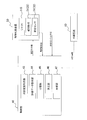
- FIG. 8 is a block configuration diagram of the position control system of the shaft 115 including the control unit 40 of the present embodiment.
- the control unit 40 has a function as a machine learning device for learning the control conditions of the magnetic bearing device 10. Specifically, the control unit 40 controls the position of the shaft 115 by using a machine learning method. More specifically, the control unit 40 uses the output value of the controlled device 50 to set conditions (position control conditions) for appropriately controlling the position of the shaft 115 by supervised learning or reinforcement learning. Learn using.
- the controlled device 50 is at least a part of the shaft 115, the magnetic bearings 21 and 22, and the displacement sensors 31 and 32.
- the control unit 40 determines the optimum position control condition for the new output value by using the learning result of the position control condition.
- the control unit 40 mainly includes a state variable acquisition unit 43, an evaluation data acquisition unit 44, a learning unit 45, a determination unit 46, and an update unit 47.
- 9A and 9B are block configuration diagrams of the control unit 40 that performs supervised learning.
- State variable acquisition unit 43 The state variable acquisition unit 43 observes the state of the magnetic bearing device 10 during the operation of the magnetic bearing device 10 and acquires information on the observed state as a state variable. In other words, the state variable acquisition unit 43 inputs the state of the magnetic bearing device 10 and outputs the state variable.
- the state variable contains at least one parameter that correlates with the position of the shaft 115. In this embodiment, the state variable is the output value of the displacement sensors 31 and 32. State variables are used as teacher data in supervised learning.
- the position of the shaft 115 is at least one of the coordinate values that regulate the five degrees of freedom excluding the angle around the rotation axis (Z axis) of the shaft 115.
- 5 degrees of freedom is the coordinate values of the center of gravity of the shaft 115 in the X-axis direction, the Y-axis direction, and the Z-axis direction, the angle around the X-axis of the shaft 115, and the Y-axis of the shaft 115.
- Another example of the five degrees of freedom is the coordinate values in the X-axis direction and the Y-axis direction of the two radial magnetic bearings 21 and the coordinate values in the Z-axis direction of the centers of gravity of the two radial magnetic bearings 21.
- the position of the center of gravity of the shaft 115 on the XY plane may be used as the position of the shaft 115.
- Evaluation data acquisition unit 44 evaluates the determination data and acquires the evaluation data.
- the evaluation data is used as teacher data in supervised learning.
- the evaluation data includes at least one of a measured value of the position of the shaft 115, a target value of the position of the shaft 115, and a parameter that correlates with the deviation of the position of the shaft 115 from the target value.
- the evaluation data acquisition unit 44 for example, inputs the determination data into a predetermined evaluation function and acquires the output value of the evaluation function as the evaluation data. In other words, the evaluation data acquisition unit 44 inputs the determination data and outputs the evaluation data.
- the determination data is, for example, data that can be used for evaluation of the position control of the shaft 115.
- the determination data is the center position (position command value) of the movable range of the shaft 115 and the detection value (position detection value) of the position of the shaft 115.
- the position command value is a target value of the position of the shaft 115.
- the position detection value is, for example, a detection value of the position of the shaft 115 obtained from the output values of the displacement sensors 31 and 32.
- the control unit 40 controls the position of the shaft 115 so that the position detection value is as close as possible to the position command value. Therefore, the evaluation data acquisition unit 44 uses the determination data to acquire the deviation of the position detection value (shaft position deviation) when the position command value is used as a reference as the evaluation data. The closer the shaft position deviation is to zero, the more preferable.
- the input value of the evaluation function is the position command value and the position detection value, and the output value of the evaluation function is the shaft position deviation.
- the evaluation function may be a function that is regarded as a constant value if the shaft position deviation is within a predetermined range.
- a predetermined range is a range in the vicinity of zero, and a constant value is zero. In other words, from the viewpoint of the position control of the shaft 115, the shaft position deviation need only remain near zero and does not have to converge to zero.
- the shaft position deviation is, for example, the absolute value of the distance between the position command value and the position detection value.
- the shaft position deviation may be the root mean square (RMS) or the root mean square (MS) of the distance from the present to a predetermined time in the past, and the overshoot amount or settling of the distance when a disturbance is forcibly applied. It may be time.
- the overshoot amount is the amount that exceeds the position command value when the position detection value exceeds (overshoots) the position command value in the process of approaching the position command value.
- the settling time is the time until the position detection value falls within a predetermined allowable range in the vicinity of the position command value in the process of approaching the position command value, and then does not come out of the allowable range. Is.
- the learning unit 45 learns a condition (position control condition) for appropriately controlling the position of the shaft 115 by using a method of supervised learning or reinforcement learning.
- the learning unit 45 learns the position control condition according to the output of the updating unit 47. Next, the operation of the learning unit 45 when supervised learning is used will be described.
- the learning unit 45 uses a pair of the state variable acquired in advance by the state variable acquisition unit 43 and the evaluation data acquired in advance by the evaluation data acquisition unit 44 as the learning data.
- the state variable is the output value of the displacement sensors 31 and 32
- the evaluation data is the shaft position deviation.
- the teacher data used by the learning unit 45 for learning is a pair of state variables and evaluation data.
- the learning unit 45 learns the position control condition by adjusting the parameter of the identification function which is a mapping from the state variable to the evaluation data according to the output of the updating unit 47.
- the purpose of learning by the learning unit 45 is to adjust the parameters of the discriminant function using the learning data so that correct or appropriate evaluation data can be obtained from the new state variable.
- the discriminant function whose parameters are sufficiently adjusted by the learning unit 45 corresponds to the trained model.
- the learning unit 45 may use a part of the teacher data as the learning data to adjust the parameters of the discrimination function and use the rest as the test data.
- the test data is data that has not been used for training, and is mainly data that is used for performance evaluation of a trained model. By using the test data, the performance of the evaluation data obtained from the new state variables can be predicted in the form of error probability with respect to the test data.
- a holdout method As a method of dividing the data acquired in advance into training data and test data, a holdout method, an intersection confirmation method, a one-pulling method (jackknife method), a bootstrap method, or the like is used.
- the learning by the learning unit 45 is classified into online learning and batch learning according to the timing when the model is updated.
- Online learning is a method of updating a conventional model at any time by using only newly acquired data every time data necessary for updating a model is acquired.
- Batch learning is a method of generating a model by collectively processing all the data to be learned at a predetermined timing after preparing all the data necessary for updating the model.
- Update section 47 updates the learning state of the learning unit 45 using the evaluation data.
- the learning unit 45 changes the parameters of the discriminant function a plurality of times according to the output (teacher data) of the update unit 47, and outputs a control condition (position control condition) from the state variable for each discriminant function whose parameters are changed.
- the update unit 47 includes a storage unit 47a and a determination unit 47b.
- the determination unit 47b determines the evaluation data and outputs the determination result.
- the storage unit 47a creates and stores teacher data from the state variables and the evaluation data based on the determination result of the evaluation data.
- the learning unit 45 learns the control conditions based on the teacher data accumulated in the storage unit 47a.
- the determination unit 46 is a condition (position control) for appropriately controlling the position of the shaft 115 from a new state variable that correlates with the position of the shaft 115 based on the learned model obtained as a result of learning by the learning unit 45. Condition) is determined and output.
- the state variable that correlates with the position of the shaft 115 is the output value of the displacement sensors 31 and 32.
- the position control condition is information for driving the magnetic bearing device 10.
- the position control condition is a current or a voltage for driving the magnetic bearing device 10, and specifically, a voltage (voltage command value) applied to the coils 65 of the magnetic bearings 21 and 22. ..
- 9A and 9B show the flow of data when determining the position control condition from a new state variable based on the trained model.
- supervised learning is performed by online learning.
- the learning unit 45 generates a trained model in advance using the data (state variables) acquired during the test operation before shipping or installation of the magnetic bearing device 10.
- the determination unit 46 determines the position control conditions based on the learned model generated in advance by the learning unit 45.
- the learning unit 45 updates the learned model using the data (state variable) newly acquired during the operation of the magnetic bearing device 10.
- the determination unit 46 determines the position control condition based on the learned model updated by the learning unit 45.
- the trained model is updated periodically, and the determination unit 46 determines the position control condition based on the latest trained model.
- supervised learning is performed by batch learning.
- the learning unit 45 generates a trained model in advance using the data (state variables) acquired during the test operation before shipping or installation of the magnetic bearing device 10.
- the determination unit 46 determines the position control conditions based on the learned model generated in advance by the learning unit 45 during the operation of the magnetic bearing device 10. This trained model is not updated after being pre-generated by the learning unit 45. In other words, the determination unit 46 determines the position control condition using the same trained model.
- control unit 40 included in the magnetic bearing device 10 generates a trained model.
- a server connected to the control unit 40 via a computer network such as the Internet may generate a trained model, or may generate a trained model by using a cloud computing service. Good.
- Supervised learning is a method of using supervised data to generate an output corresponding to unknown input data.
- learning data and discriminant functions are used.
- the training data is a set of pairs of input data and corresponding teacher data.
- the input data is, for example, a feature vector in the feature space.
- Teacher data is, for example, parameters relating to the identification, classification and evaluation of input data.
- the discriminant function represents a mapping from the input data to the corresponding output.
- Supervised learning is a method of adjusting the parameters of the discriminant function by using the learning data given in advance so that the error between the output of the discriminant function and the supervised data becomes small.
- Models or algorithms used in supervised learning include regression analysis, time series analysis, decision trees, support vector machines, neural networks, ensemble learning, and the like.
- Regression analysis is, for example, linear regression analysis, multiple regression analysis, logistic regression analysis.
- Regression analysis is a method of fitting a model between input data (explanatory variable) and teacher data (objective variable) using the least squares method or the like.
- the dimension of the explanatory variable is 1 in linear regression analysis and 2 or more in multiple regression analysis.
- logistic regression analysis a logistic function (sigmoid function) is used as a model.
- Time series analysis includes, for example, AR model (autoregressive model), MA model (autoregressive average model), ARMA model (autoregressive moving average model), ARIMA model (autoregressive sum moving average model), SARIMA model (seasonal self Regressive sum moving average model), VAR model (vector autoregressive model).
- AR model autoregressive model
- MA model autoregressive average model
- ARMA model autoregressive moving average model
- ARIMA model autoregressive sum moving average model
- SARIMA model seasonal self Regressive sum moving average model
- VAR model vector autoregressive model
- the AR, MA, ARMA, and VAR models represent stationary processes, and the ARIMA, SARIMA models represent non-stationary processes.
- the AR model is a model in which the value changes regularly with the passage of time.
- the MA model is a model in which the fluctuation over a certain period is constant. For example, in the MA model, the value at a certain point in time is determined by the moving average
- the ARMA model is a combination of the AR model and the MA model.
- the ARIMA model is a model in which the ARMA model is applied to the difference between the values before and after in consideration of the medium- to long-term trend (increasing or decreasing trend).
- the SARIMA model is a model to which the ARIMA model is applied in consideration of medium- to long-term seasonal fluctuations.
- the VAR model is a multivariate extension of the AR model.
- the decision tree is a model for combining multiple classifiers to generate complex discriminant boundaries. The details of the decision tree will be described later.
- the support vector machine is an algorithm that generates two classes of linear discrimination functions. Details of the support vector machine will be described later.
- a neural network is a model of a network formed by connecting neurons of the human cranial nerve system at synapses.
- a neural network in a narrow sense, means a multi-layer perceptron using the backpropagation method.
- Typical neural networks include convolutional neural networks (CNN) and recurrent neural networks (RNN).
- CNN is a type of feedforward neural network that is not fully coupled (loosely coupled).
- RNN is a kind of neural network having a directed cycle.
- CNNs and RNNs are used for voice / image / video recognition and natural language processing.
- Ensemble learning is a method of improving discrimination performance by combining multiple models.
- Techniques used by ensemble learning are, for example, bagging, boosting, and random forest.
- Bagging is a method in which a plurality of models are trained using a bootstrap sample of training data, and the evaluation of new input data is determined by a majority decision by the plurality of models.
- Boosting is a method of weighting training data according to the learning result of bagging so that erroneously identified learning data is trained more intensively than correctly identified learning data.
- Random forest is a method of generating a decision tree group (random forest) consisting of a plurality of decision trees having low correlation when a decision tree is used as a model. The details of Random Forest will be described later.
- the neural network, the support vector machine, the decision tree, and the random forest described below are used as the preferred model or algorithm for supervised learning used by the learning unit 45.
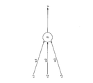
- FIG. 10 is a schematic diagram of a neuron model of a neural network.
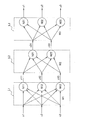
- FIG. 11 is a schematic diagram of a three-layer neural network configured by combining the neurons shown in FIG.
- the neuron outputs an output y for a plurality of inputs x (inputs x1, x2, x3 in FIG. 10).
- Each input x (inputs x1, x2, x3 in FIG. 10) is multiplied by a corresponding weight w (weights w1, w2, w3 in FIG. 10).
- the neuron outputs the output y using the following equation (1).
- the input x, the output y and the weight w are all vectors, ⁇ is a bias, and ⁇ is an activation function.
- the activation function is a non-linear function, such as a step function (formal neuron), a simple perceptron, a sigmoid function or a ReLU (ramp function).
- a plurality of input vectors x (input vectors x1, x2, x3 in FIG. 11) are input from the input side (left side in FIG. 11), and the output side (right side in FIG. 11).
- a plurality of output vectors y (output vectors y1, y2, y3 in FIG. 11) are output from.
- This neural network is composed of three layers L1, L2, and L3.
- the input vectors x1, x2, x3 are input by applying the corresponding weights to each of the three neurons N11, N12, and N13. In FIG. 11, these weights are collectively referred to as W1.
- the neurons N11, N12, and N13 output the feature vectors z11, z12, and z13, respectively.
- the feature vectors z11, z12, and z13 are input by applying corresponding weights to each of the two neurons N21 and N22. In FIG. 11, these weights are collectively referred to as W2.
- the neurons N21 and N22 output the feature vectors z21 and z22, respectively.
- the feature vectors z21 and z22 are input by applying corresponding weights to each of the three neurons N31, N32 and N33. In FIG. 11, these weights are collectively referred to as W3.
- the neurons N31, N32, and N33 output output vectors y1, y2, and y3, respectively.
- the operation of the neural network has a learning mode and a prediction mode.
- the weights W1, W2, and W3 are learned using the learning data set.
- prediction such as identification is performed using the learned parameters of the weights W1, W2, and W3.
- the weights W1, W2, and W3 can be learned by, for example, the error backpropagation method (backpropagation).
- the error backpropagation method learns by adjusting the weights W1, W2, and W3 in each neuron so as to reduce the difference between the output y when the input x is input and the true output y (teacher data). It is a method to do.
- the neural network can be configured to have more than three layers.
- a machine learning method using a neural network having four or more layers is known as deep learning.
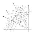
- FIG. 12 is a diagram for explaining SVM.
- the two-class linear discrimination function represents the discrimination hyperplanes P1 and P2, which are hyperplanes for linearly separating the training data of the two classes C1 and C2 in the feature space shown in FIG.
- the training data of class C1 is shown by a circle
- the learning data of class C2 is shown by a square.
- the margin of the identification hyperplane is the distance between the training data closest to the identification hyperplane and the identification hyperplane.
- the optimum identification hyperplane P1 which is the identification hyperplane that maximizes the margin is required.
- the minimum value d1 of the distance between the training data of one class C1 and the optimal identification hyperplane P1 is equal to the minimum value d1 of the distance between the training data of the other class C2 and the optimal identification hyperplane P2.
- the number of elements of the training dataset D L is N.
- the teacher data t i represents whether the learning data x i belongs to the classes C1 and C2.
- the margin d is represented by the equation (6).
- ⁇ (w) denotes the class C1, the respective minimum length difference which is projected onto the normal vector w of learning data x i identification hyperplane P1, P2 of C2.
- the "min” and “max” terms of the formula (6) are the points indicated by the symbols “min” and “max” in FIG. 12, respectively.
- the optimum identification hyperplane is the identification hyperplane P1 having the maximum margin d.
- FIG. 12 represents a feature space in which the two classes of training data are linearly separable.
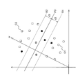
- FIG. 13 is a feature space similar to that of FIG. 12, and represents a feature space in which the two classes of training data cannot be linearly separated.
- the following equation (7) extended by introducing the slack variable ⁇ i into the equation (4) can be used.
- FIG. 13 shows the identification hyperplane P3, the margin boundaries B1 and B2, and the margin d3.
- the equation of the identification hyperplane P3 is the same as the equation (5).
- the margin boundaries B1 and B2 are hyperplanes in which the distance from the identification hyperplane P3 is the margin d3.
- equation (7) is equivalent to equation (4).
- the learning data x i that satisfies the equation (7) is correctly identified in the margin d3.
- the distance between the learning data x i and the identification hyperplane P3 is margin d3 more.
- the training data x i satisfying equation (7) exceeds the margin boundaries B1 and B2, as shown by the hatched circle or square in FIG. , The identification hyperplane P3 is not exceeded and is correctly identified. The distance between the learning data x i and the identification hyperplane P3 is less than the margin d3.
- the learning data x i satisfying the equation (7) exceeds the identification hyperplane P3 and is erroneously recognized, as shown by the black circle or square in FIG. ..
- the training data x i can be identified even when the training data of the two classes cannot be linearly separated.
- the sum of the slack variables ⁇ i of all the training data x i represents the upper limit of the number of misrecognized learning data x i .
- the evaluation function L p is defined by the following equation (8).
- the learning unit 45 finds a solution (w, ⁇ ) that minimizes the output value of the evaluation function L p .
- the parameter C of the second term represents the strength of the penalty for misrecognition. As the parameter C is larger, a solution that gives priority to reducing the number of false recognitions (second term) rather than the norm of w (first term) is required.
- a decision tree is a model for combining a plurality of classifiers to obtain a complicated discriminant boundary (non-linear discriminant function, etc.).
- the discriminator is, for example, a rule regarding the magnitude relationship between the value of a certain feature axis and the threshold value.
- As a method of constructing a decision tree from learning data for example, there is a divide-and-conquer method in which a rule (discriminator) for dividing a feature space into two is repeatedly obtained.
- FIG. 14 is an example of a decision tree constructed by the divide-and-conquer law.
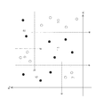
- FIG. 15 represents a feature space divided by the decision tree of FIG. In FIG.
- the training data is indicated by white circles or black circles, and each training data is classified into a white circle class or a black circle class according to the decision tree shown in FIG.
- FIG. 14 shows nodes numbered 1 to 11 and links linking the nodes and labeled Yes or No.
- terminal nodes leaf nodes
- non-terminal nodes root nodes and internal nodes
- Terminating nodes are nodes numbered 6 to 11, and non-terminating nodes are nodes numbered 1 to 5.
- Each terminal node is indicated by a white circle or a black circle representing the training data.
- Each non-terminating node has a classifier.
- Classifier is a rule for determining the size relationship between the value of the feature axis x 1, x 2 and the threshold a ⁇ e.
- the label attached to the link indicates the judgment result of the classifier.
- the classifiers are shown by dotted lines, and the areas divided by the classifiers are numbered with corresponding nodes.
- CART is a method of generating a binary tree as a decision tree by dividing the feature space into two for each feature axis in each node other than the terminal node.
- impureness may be used as a parameter for evaluating the division candidate points of the feature space.
- the function I (t) representing the purity of the node t
- the parameters represented by the following equations (9-1) to (9-3) are used.
- K is the number of classes.
- t) is the posterior probability of class C i at the node t, in other words, the probability that the data of class C i is selected at the node t.
- t) is the probability that the data of the class C i is mistaken for the j ( ⁇ i) th class. Represents the error rate at t.
- the third equation of equation (9-3) represents the sum of the variances of the probabilities P (C i
- Random forest Random forest is a kind of ensemble learning, and is a method of enhancing discrimination performance by combining a plurality of decision trees.
- a group consisting of multiple decision trees with low correlation is generated.
- A From N d-dimensional learning data, m bootstrap samples Z m are generated.
- B Using Z m as training data, each node t is divided according to the following procedure to generate m decision trees.
- d'features are randomly selected.
- the correlation between decision trees can be lowered by randomly selecting a predetermined number of features used for identification at each non-terminal node of the decision tree.
- Reinforcement learning is a method of learning a strategy that maximizes the reward as a result of a series of actions.
- Models or algorithms used in reinforcement learning include Q-learning.
- Q-learning is a method of learning a Q value representing the value of selecting an action a under the state s.
- the action a having the highest Q value is selected as the optimal action.
- the subject (agent) of the action a is rewarded for the action a selected under the state s.
- the Q value is updated using the following equation (10).
- Q (s t , a t) is the Q value representing the value that the agent state s t to select an action a t.
- Q (s t, a t) is a function of the state s and action a as a parameter (action-value function).
- st is the state of the agent at time t.
- a t is the action of the agent at time t.
- ⁇ is a learning coefficient.
- ⁇ is set by Eq. (10) so that the Q value converges to the optimum value.
- r t + 1 is the reward that the agent gets when it transitions to the state st + 1 .
- ⁇ is the discount rate.
- ⁇ is a constant of 0 or more and 1 or less.
- the term including max is the Q value multiplied by ⁇ when the action a having the highest Q value is selected under the environment st + 1 .
- the Q value obtained by the action value function is the expected value of the reward obtained
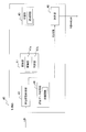
- FIG. 16 is a block configuration diagram of the control unit 40 that performs reinforcement learning by Q-learning.
- the control unit 40 mainly has a state variable acquisition unit 143, a learning unit 145, and a determination unit 146.
- the state variable acquisition unit 143 and the determination unit 146 have the same functions as the state variable acquisition unit 43 and the determination unit 46 shown in FIGS. 9A and 9B, respectively.
- the learning unit 145 has a reward condition setting unit 145a, a reward calculation unit 145b, and a function update unit 145c.
- the reward condition setting unit 145a sets the reward condition.
- the reward calculation unit 145b calculates the reward based on the state variable acquired by the state variable acquisition unit 143 and the reward condition set by the reward condition setting unit 145a.
- the function update unit 145c updates the action value function based on the reward calculated by the reward calculation unit 145b.
- the action value function is a function for obtaining a Q value, which is the value of selecting a predetermined action under the state variable acquired by the state variable acquisition unit 143.
- the function update unit 145c updates the action value function by using, for example, the equation (10).
- the function update unit 145c outputs the optimized action value function as a trained model. In this way, the learning unit 145 learns the policy that maximizes the reward by adjusting the parameters of the behavior value function and updating the behavior value function based on the state variables, and generates a trained model. ..
- the learning unit 145 uses the reward to perform reinforcement learning by online learning.
- the learning unit 45 may use various machine learning techniques.
- Machine learning methods that can be used by the learning unit 45 include unsupervised learning, semi-supervised learning, transductive learning, multitasking learning, transfer learning, and the like, in addition to the supervised learning and reinforcement learning already described.
- the learning unit 45 may use these methods in combination.
- Unsupervised learning is a method of grouping (clustering) input data based on predetermined statistical properties without using teacher data.
- Models or algorithms used in unsupervised learning include k-means method (k-means method), Ward's method (Ward method), principal component analysis, and the like.
- the k-means method is a method of repeating the steps of randomly allocating clusters to each input data, calculating the center of each cluster, and reassigning each input data to the cluster of the closest center.
- Ward's method is a method of repeating the process of reassigning each input data to a cluster so as to minimize the distance from each input data of the cluster to the center of mass of the cluster.
- Principal component analysis is a multivariate analysis method that generates a variable called the principal component with the smallest correlation from a plurality of correlated variables.
- Semi-supervised learning is a method of learning using both input data without corresponding teacher data (unlabeled data) and input data with corresponding teacher data (labeled data).
- Transductive learning is a method in semi-supervised learning that generates an output corresponding to unlabeled data used for learning and does not generate an output corresponding to unknown input data.
- Multitask learning is a method of sharing information between multiple related tasks and learning these tasks at the same time to acquire common factors for the tasks and improve the prediction accuracy of the tasks.
- Transfer learning is a method of improving prediction accuracy by adapting a model trained in advance in one domain to another domain.
- control unit 40 uses the supervised learning method, the control unit 40 uses each data of the state variable, the evaluation data, and the control condition.
- the state variable contains at least one parameter that correlates with the position of the shaft 115.
- the state variable acquisition unit 43 acquires the output values of the displacement sensors 31 and 32 as the state variables.
- the evaluation data includes at least one parameter that correlates with the deviation of the position of the shaft 115 from the target value.
- the evaluation data acquisition unit 44 acquires the shaft position deviation, which is the difference between the detected value of the position of the shaft 115 and the target value of the position of the shaft 115, as the evaluation data.
- the detected value is a value converted from the output values of the displacement sensors 31 and 32.
- the target value is the central position of the movable range of the shaft 115.
- the control conditions are learned by the learning unit 45 and are conditions for appropriately controlling the position of the shaft 115.
- the learning unit 45 learns the control conditions for reducing the shaft position deviation.
- the determination unit 46 determines at least one of the voltage (voltage command value) applied to the coil 65 of the electromagnet of the magnetic bearings 21 and 22 and the current (current command value) flowing through the coil 65 as control conditions.
- control unit 40 uses the state variable and the reward condition.
- the state variables are the same as the state variables used when the control unit 40 uses the supervised learning method.
- the control unit 40 calculates a reward from the shaft position deviation based on a predetermined reward condition.
- the reward condition is set so that the reward increases when the shaft position deviation is small and the reward decreases or does not change when the shaft position deviation is large.
- the reward condition is, for example, a condition for calculating the reward based on the evaluation data.
- the magnetic bearing device 10 included in the air conditioner 100 of the present embodiment adjusts the voltage (voltage command value) applied to the coil of the magnetic bearing to control the position of the magnetically levitated shaft 115. Equipped with a system.
- the conventional position control system adjusts the voltage command value and the like based on a predetermined control rule. In this case, if an appropriate voltage command value cannot be obtained due to variations in the quality of the device, changes over time in the system, etc., the stability of the levitation control of the shaft deteriorates, or a large disturbance force is generated during levitation.
- the shaft may come into contact with the touchdown bearing.
- the control unit 40 having a learning function appropriately controls the position of the shaft 115 based on the state variables correlating with the position of the shaft 115 and the evaluation data regarding the position of the shaft 115.
- the conditions for performing are learned using a supervised learning method. Since the displacement sensors 31 and 32 detect the position of the shaft 115 at a relatively short time interval (for example, every 40 ⁇ s), the control unit 40 can control the position of the shaft 115 at a relatively short time interval. .. Therefore, the control unit 40 can maintain the stability of the position control of the shaft 115 for a long period of time.
- the quality of the magnetic bearing device 10 varies, the stability of the levitation control of the shaft 115 deteriorates due to changes over time of the system, and the contact between the shaft 115 and the touchdown bearings 116, 117 due to disturbance force. The occurrence can be suppressed.
- the state variable acquisition unit 43 acquires the output values of the displacement sensors 31 and 32 as state variables.
- the output values of the displacement sensors 31 and 32 are parameters that correlate with the position of the shaft 115.
- the state variable acquisition unit 43 acquires parameters other than the output values of the displacement sensors 31 and 32 as state variables and correlates with the position of the shaft 115. Therefore, this embodiment can be applied to a sensorless type magnetic bearing device that does not have displacement sensors 31 and 32.
- the state variable acquisition unit 43 acquires information on the species required for estimating the position of the shaft 115 as a state variable.
- the information necessary for estimating the position of the shaft 115 includes at least two of the current detection value, the voltage detection value, the magnetic flux detection value, the current command value and the voltage command value of the electromagnets of the magnetic bearings 21 and 22.
- the current detection value is a detection value of the current flowing through the coil 65 of the electromagnet.
- the voltage detection value is a detection value of the voltage applied to the coil 65 of the electromagnet.
- the magnetic flux detection value is a detection value of the magnetic field generated from the coil 65 of the electromagnet.
- the magnetic flux detection value is, for example, an output value of a hall sensor which is a non-contact type magnetic sensor.
- the current command value is a current value controlled by the control unit 40 and input to the coil 65 of the electromagnet.
- the voltage command value is a voltage value controlled by the control unit 40 and input to the coil 65 of the electromagnet
- Examples of the information required for estimating the position of the shaft 115 include the following information (a) to (c).
- the state variable acquisition unit 43 estimates the position of the shaft 115 by inputting the voltage command value and acquiring the current detection value.
- the state variable acquisition unit 43 estimates the position of the shaft 115 by inputting the current command value and acquiring the voltage detection value.
- the state variable acquisition unit 43 utilizes the property that the current (or current derivative value) and the voltage of the coil 65 correlate with the position of the shaft 115, so that the position of the shaft 115 is used. To estimate.
- the current or voltage may be input in a sinusoidal manner or in a stepped manner.
- the state variable acquisition unit 43 estimates the position of the shaft 115 by utilizing the property that the current detection value and the magnetic flux detection value correlate with the position of the shaft 115.
- the evaluation data acquisition unit 44 acquires the shaft position deviation, which is the difference between the estimated value of the position of the shaft 115 converted from the state variable and the target value of the position of the shaft 115, as the evaluation data.
- the learning unit 45 learns the control conditions for reducing the shaft position deviation.
- the determination unit 46 determines at least one of the voltage (voltage command value) applied to the coil 65 of the electromagnet of the magnetic bearings 21 and 22 and the current (current command value) flowing through the coil 65 as control conditions.
- the first and second embodiments relate to a configuration in which all the functions of the position detection unit 941, the position control unit 942, and the current control unit 943 shown in FIG. 7 have a learning function.
- the third to fifth embodiments described below relate to a configuration in which only one of the functions of the conventional control unit 940, the position detection unit 941, the position control unit 942, and the current control unit 943, has a learning function.
- FIG. 17 is a block configuration diagram of the position control system of the shaft 115 in the present embodiment. As shown in FIG. 17, the block corresponding to the position detection unit 941 in FIG. 7 is replaced with the learning control unit 340 having a learning function.
- the learning control unit 340 has the same function as the control unit 40 of the first and second embodiments. In other words, the learning control unit 340 has a state variable acquisition unit 43, an evaluation data acquisition unit 44, a learning unit 45, and a determination unit 46, as shown in FIGS. 9A and 9B.
- the differences from the control unit 40 of the first and second embodiments will be mainly described.
- the evaluation data acquisition unit 44 uses the target value (position command value) of the position of the shaft 115 and the detection value (position detection value) of the position of the shaft 115 as the determination data.
- the evaluation data acquisition unit 44 uses the target value of the parameter (correlation parameter) that correlates with the position of the shaft 115 and the detection value of the correlation parameter as the determination data instead of the position command value and the position detection value.
- the correlation parameter the state variable acquired by the state variable acquisition unit 43 in the first and second embodiments is used.
- the evaluation data acquisition unit 44 may use the output values of the displacement sensors 31 and 32 described in the first embodiment as the correlation parameter, and is necessary for estimating the position of the shaft 115 described in the second embodiment. Information may be used.
- the evaluation data acquisition unit 44 acquires, for example, the deviation of the detected value of the correlation parameter (correlation parameter deviation) as the evaluation data when the target value of the correlation parameter is used as a reference, using the determination data.
- the learning unit 45 learns the control conditions for reducing the correlation parameter deviation.
- the determination unit 46 determines the position detection value as a condition (position control condition) for appropriately controlling the position of the shaft 115.
- the learning unit 45 may learn the position control condition at a specific time point.
- the specific time point is a time point at which the position of the shaft 115 can be specified or estimated based on the correlation parameter.
- the specific time point is a time point when the position of the shaft 115 is restricted to a certain degree, or a time point when the force applied to the shaft 115 is known.
- the time when the position of the shaft 115 is restricted is, for example, the time when the shaft 115 is in contact with the touchdown bearings 116 and 117.
- the time when the force applied to the shaft 115 is known is, for example, the time when the shaft 115 is free-falling.
- the evaluation data acquisition unit 44 may acquire the true value of the position of the shaft 115 as the evaluation data instead of the correlation parameter deviation.
- the position detection value included in the determination data may be used.
- the position of the shaft 115 specified or estimated at the above-mentioned "specific time point" may be used as the true value of the position of the shaft 115.
- FIG. 18 is a block configuration diagram of the position control system for the shaft 115 in the present embodiment. As shown in FIG. 18, the block corresponding to the position control unit 942 in FIG. 7 is replaced with the learning control unit 440 having a learning function.
- the learning control unit 440 has the same function as the control unit 40 of the first and second embodiments. In other words, the learning control unit 440 has a state variable acquisition unit 43, an evaluation data acquisition unit 44, a learning unit 45, and a determination unit 46, as shown in FIGS. 9A and 9B.
- the differences from the control unit 40 of the first and second embodiments will be mainly described.
- the state variable acquisition unit 43 uses the target value (position command value) of the position of the shaft 115 and the detection value (position detection value) of the position of the shaft 115 as the state variables.
- the evaluation data acquisition unit 44 uses the position command value and the position detection value as the determination data.
- the evaluation data acquisition unit 44 acquires the shaft position deviation, which is the difference between the position command value and the position detection value, as the evaluation data.
- the learning unit 45 learns the control conditions for reducing the shaft position deviation.
- the determination unit 46 flows the voltage (voltage command value) applied to the coil 65 of the electromagnet of the magnetic bearings 21 and 22 and the coil 65 as conditions (position control conditions) for appropriately controlling the position of the shaft 115. Determine at least one of the currents (current command values).
- FIG. 19 is a block configuration diagram of the position control system of the shaft 115 in the present embodiment. As shown in FIG. 19, the block corresponding to the current control unit 943 in FIG. 7 is replaced with the learning control unit 540 having a learning function.
- the learning control unit 540 has the same function as the control unit 40 of the first and second embodiments. In other words, the learning control unit 540 has a state variable acquisition unit 43, an evaluation data acquisition unit 44, a learning unit 45, and a determination unit 46, as shown in FIGS. 9A and 9B.
- the differences from the control unit 40 of the first and second embodiments will be mainly described.
- the state variable acquisition unit 43 uses the current flowing through the coil 65 of the electromagnet of the magnetic bearings 21 and 22 (current command value) and the position detection value (position detection value) of the shaft 115 as state variables. get.
- the evaluation data acquisition unit 44 uses the current command value and the position detection value as the determination data.
- the evaluation data acquisition unit 44 acquires an amount (response level) related to the responsiveness of the current control as the evaluation data. The closer the response level is to zero, the more preferable the parameter.
- the response level may be, for example, the absolute value of the deviation of the current detection value based on the current command value, the root mean square (RMS) or the root mean square (MS), and when a disturbance is forcibly applied. It may be the overshoot amount or the settling time of the deviation.
- the learning unit 45 learns the control conditions for reducing the response level.
- the determination unit 46 determines the voltage (voltage command value) applied to the coil 65 of the electromagnet of the magnetic bearings 21 and 22 as a condition (position control condition) for appropriately controlling the position of the shaft 115.
- the evaluation data acquisition unit 44 further uses a parameter correlating with the current value for driving the magnetic bearings 21 and 22 as determination data.
- the evaluation data acquisition unit 44 further acquires the current value for driving the magnetic bearings 21 and 22 as evaluation data.
- the updating unit 47 trains the learning unit 45 so that the current value for driving the magnetic bearings 21 and 22 is set to a predetermined value or less.
- the predetermined value is an allowable current value of the inverter for driving the magnetic bearings 21 and 22.
- the evaluation data acquisition unit 44 further uses a parameter that correlates with the temperature of the inverter for driving the magnetic bearings 21 and 22 as determination data.
- the evaluation data acquisition unit 44 further acquires the temperature of the inverter for driving the magnetic bearings 21 and 22 as evaluation data.
- the update unit 47 trains the learning unit 45 so that the temperature of the inverter becomes equal to or lower than a predetermined value.
- the predetermined value is the allowable temperature of the inverter.
- the state variable acquisition unit 43 uses the magnetic bearing 21, as a state variable, when the magnetic bearings 21 and 22 are driven by a voltage type inverter.
- the current detection value of the electromagnet of 22 is further acquired, and the voltage detection value of the electromagnet of the magnetic bearings 21 and 22 is further acquired when the magnetic bearings 21 and 22 are driven by the current type inverter.
- the evaluation data acquisition unit 44 further uses the current command value and the position detection value as the determination data.
- the evaluation data acquisition unit 44 further acquires an amount (response level) related to the responsiveness of the current control as the evaluation data. The closer the response level is to zero, the more preferable the parameter.
- the response level may be, for example, the absolute value of the deviation of the current detection value based on the current command value, the root mean square (RMS) or the root mean square (MS), and when a disturbance is forcibly applied. It may be the overshoot amount or the settling time of the deviation.
- the update unit 47 trains the learning unit 45 so as to reduce the response level.
- the state variable acquisition unit 43 further acquires the rotation speed of the shaft 115 as a state variable.
- the state variable acquisition unit 43 further acquires at least one parameter that correlates with the operating conditions of the air conditioner 100 as a state variable.
- the operating conditions of the air conditioner 100 are a predetermined range of the refrigerating capacity of the air conditioner 100 and the inlet water temperature of the condenser 120.
- the inlet water temperature is the temperature of water which is a medium for heat exchange with the refrigerant circulating in the refrigerant circuit 190 of the air conditioner 100, and is the temperature of water when flowing into the condenser 120.
- FIG. 20 is an example of operating conditions of the air conditioner 100.
- the unit of refrigerating capacity of the air conditioner 100 is a refrigerating ton.
- the unit of the inlet water temperature of the condenser 120 is Fahrenheit.
- the hatched region in FIG. 20 is the operating condition of the air conditioner 100, and is the range in which the air conditioner 100 can achieve air conditioning.
- the parameters that correlate with the operating conditions of the air conditioner 100 are, specifically, data related to the operation information of the air conditioner 100 listed below.
- (A) Temperature of the refrigerant sucked into the compressor 110 (b) Temperature of the refrigerant discharged from the compressor 110 (c) Pressure of the refrigerant sucked into the compressor 110 (d) Refrigerant discharged from the compressor 110 (E) Flow rate of the refrigerant circulating in the refrigerant circuit 190 (f) Temperature of the water flowing into the compressor 120 (g) Temperature of the water flowing out of the compressor 120 (h) Temperature of the water flowing into the evaporator 140 (I) Temperature of water flowing out from the evaporator 140 (j) Opening of inlet guide vane 113b (k) Number of rotations of the electric motor 114 (l) Rotation angle of the electric motor 114 (m) Torque of the electric motor 114 (n) Electric motor 114 Current value of
- Water in the parameters (f) to (i) means water which is a medium for heat exchange with the refrigerant in the condenser 120 or the evaporator 140.
- the parameter that correlates with the operating conditions of the air conditioner 100 includes at least one of the above parameters (a) to (n).
- the parameters that correlate with the operating conditions of the air conditioner 100 may further include information about the type of refrigerant.
- control unit 40 can learn the optimum control conditions for each operating condition of the air conditioner 100.
- the state variable acquisition unit 43 further acquires at least one parameter that correlates with the electromagnetic force applied to the shaft 115 as a state variable.
- the parameter that correlates with the electromagnetic force applied to the shaft 115 includes at least one of the parameter that correlates with the refrigerant load of the air conditioner 100 and the parameter that correlates with the physical property of the air conditioner 100.
- the parameter that correlates with the refrigerant load of the air conditioner 100 includes at least one of the parameters (a) to (n) listed in the modified example F.
- the parameters that correlate with the refrigerant load of the air conditioner 100 may further include information about the type of refrigerant.
- the parameters that correlate with the physical properties of the air conditioner 100 are the weight of the shaft 115 and at least one of the forces acting on the shaft 115.
- the force acting on the shaft 115 is at least one of the Coriolis force acting on the shaft 115 and the centrifugal force acting on the shaft 115.
- a parameter that correlates with the amount of eccentricity of the shaft 115 and at least one of the rotation speeds of the motor 114 may be used.
- the state variable acquisition unit 43 further acquires at least one parameter that correlates with the characteristics of the magnetic bearings 21 and 22 as a state variable.
- the parameter that correlates with the characteristics of the magnetic bearings 21 and 22 includes at least one parameter that correlates with the inductance of the coil 65 of the electromagnet of the magnetic bearings 21 and 22 and a parameter that correlates with the resistance of the coil 65.
- the parameter that correlates with the inductance of the coil 65 is, for example, a detected value of the current flowing through the coil 65.
- the parameters that correlate with the resistance of the coil 65 are parameters that correlate with the temperature of the coil 65 or the temperature around the coil 65, and specifically, the parameters (a) to (i) listed in the modified example F. ) Includes at least one.
- the parameters that correlate with the resistance of the coil 65 may further include information about the type of refrigerant.
- the evaluation data acquisition unit 44 further uses a parameter correlating with the power consumption of the magnetic bearings 21 and 22 as determination data.
- the parameters that correlate with the power consumption of the magnetic bearings 21 and 22 are the parameters that correlate with the current value for driving the magnetic bearings 21 and 22, the parameters that correlate with the voltage value for driving the magnetic bearings 21 and 22, and the parameters. , Includes at least two of the parameters that correlate with the resistance of the electromagnet coil 65 of the magnetic bearings 21 and 22.
- the parameter that correlates with the current value for driving the magnetic bearings 21 and 22 is, for example, the detected value of the current flowing through the coil 65.
- the parameters that correlate with the resistance of the coil 65 are parameters that correlate with the temperature of the coil 65 or the temperature around the coil 65, and specifically, the parameters (a) to (i) listed in the modified example F. ) Includes at least one.
- the parameters that correlate with the resistance of the coil 65 may further include information about the type of refrigerant.
- the evaluation data acquisition unit 44 further acquires the power consumption of the magnetic bearings 21 and 22 as evaluation data.
- the updating unit 47 trains the learning unit 45 so as to reduce the power consumption of the magnetic bearings 21 and 22.
- control unit 40 can learn the control conditions that can suppress the power consumption of the air conditioner 100.
- the state variable acquisition unit 43 further acquires at least one parameter that correlates with the operating conditions of the air conditioner 100 as a state variable.
- the parameter that correlates with the operating conditions of the air conditioner 100 includes at least one of the parameters (a) to (n) listed in the modified example F.
- the parameters that correlate with the operating conditions of the air conditioner 100 may further include information about the type of refrigerant.
- the evaluation data acquisition unit 44 correlates with at least the input energy supplied to the compressor 110 driven by the electric motor 114 as determination data.
- the parameters that correlate with the input energy are the input current of the magnetic bearings 21 and 22, the input power of the magnetic bearings 21 and 22, the input current of the inverter for driving the magnetic bearings 21 and 22, and the magnetic bearings 21 and 22. Includes at least one of the input power of the inverter for, the input current of the motor 114, the input power of the motor 114, the input current of the inverter for driving the motor 114, and the input power of the inverter for driving the motor 114. ..
- the evaluation data acquisition unit 44 further acquires the input energy supplied to the compressor 110 as the evaluation data.
- the update unit 47 trains the learning unit 45 so that the input energy supplied to the compressor 110 is reduced.
- control unit 40 can learn the control conditions that minimize the input energy supplied to the compressor 110.
- the state variable acquisition unit 43 uses at least one parameter that correlates with the operating conditions of the air conditioner 100 as a state variable, and the heat insulation efficiency of the impeller 113a connected to the shaft 115. Further obtain at least one of at least one parameter that correlates with.
- the parameter that correlates with the operating conditions of the air conditioner 100 includes at least one of the parameters (a) to (n) listed in the modified example F.
- the parameters that correlate with the operating conditions of the air conditioner 100 may further include information about the type of refrigerant.
- the parameter that correlates with the heat insulation efficiency of the impeller 113a includes at least one of the parameter that correlates with the pressure of the refrigerant and the parameter that correlates with the temperature of the refrigerant.
- the parameter that correlates with the pressure of the refrigerant includes at least one of the parameters (a) to (e) listed in the modified example F.
- the parameters that correlate with the pressure of the refrigerant may further include information about the type of refrigerant.
- the parameter that correlates with the temperature of the refrigerant includes at least one of the parameters (a) to (i) listed in the modified example F.
- the parameters that correlate with the temperature of the refrigerant may further include information about the type of refrigerant.
- control unit 40 can learn the control conditions that maximize the heat insulation efficiency of the impeller 113a.
- the state variable acquisition unit 43 further acquires a parameter that correlates with the temperature of the displacement sensors 31 and 32 when acquiring the output values of the displacement sensors 31 and 32 as the state variable.
- the parameters that correlate with the temperature of the displacement sensors 31 and 32 include at least one of the parameters (a) to (i) listed in the modification F.
- the parameters that correlate with the temperature of the refrigerant may further include information about the type of refrigerant.
- control unit 40 can compensate for the deviation of the detected values of the displacement sensors 31 and 32 due to the temperature by using the information on the temperature of the displacement sensors 31 and 32 having the temperature characteristics as a state variable. Therefore, the control unit 40 acquires the estimated value of the positions of the touchdown bearings 116 and 117 with high accuracy, and aligns the shaft 115 so that the rotation axis of the shaft 115 approaches the center of the touchdown bearings 116 and 117. It can be performed.
- Calibration of the displacement sensors 31 and 32 is performed by forcibly changing parameters such as the position of the shaft 115, the current value of the coil 65 of the electromagnet of the magnetic bearings 21 and 22, and the voltage value of the coil 65. ..
- a periodic waveform may be superimposed on these parameters, these parameters may be changed in steps, or these parameters may be changed in a ramp shape.
- Periodic waveforms are, for example, sine waves, square waves, triangular waves and sawtooth waves.
- the frequency of the periodic waveform may be changed intermittently or continuously.
- the displacement sensors 31 and 32 may be calibrated by superimposing the position command value of the shaft 115 and the perturbation by a predetermined waveform.
- the predetermined waveform is, for example, a periodic waveform, a pulse waveform, and a step waveform.
- Periodic waveforms are, for example, sine waves, square waves, triangular waves and sawtooth waves.
- the displacement sensors 31 and 32 may be calibrated by setting a certain restriction on the position of the shaft 115. For example, an operation of bringing the shaft 115 into contact with the touchdown bearings 116 and 117 and an operation of which the force acting on the shaft 115 is known may be performed.
- the operation in which the force acting on the shaft 115 is known is, for example, an operation when the shaft 115 is freely falling.
- control unit 40 learns the conditions for appropriately controlling the position of the shaft 115 by using the method of supervised learning or reinforcement learning.
- the control unit 40 may learn the conditions for appropriately controlling the position of the shaft 115 by using a method that combines supervised learning and reinforcement learning.
- the radial magnetic bearing 21 may use a support mechanism of a bearingless motor (an electric motor having a function of supporting the shaft in a non-contact manner).
- the magnetic bearing device can appropriately control the position of the supported body.
- Magnetic bearing device 21 Radial magnetic bearing (magnetic bearing) 22 Thrust magnetic bearing (magnetic bearing) 31 Radial displacement sensor (displacement sensor) 32 Thrust displacement sensor (displacement sensor) 43 State variable acquisition unit 44 Evaluation data acquisition unit 45 Learning unit 46 Decision unit 47 Update unit 47a Storage unit 47b Judgment unit 51 First electromagnet (electromagnet) 52 Second electromagnet (electromagnet) 53 Third electromagnet (electromagnet) 54 4th electromagnet (electromagnet) 100 Air conditioner (freezing device) 110 Compressor 113a Impeller 115 Shaft 120 Condenser 130 Expansion mechanism 140 Evaporator 190 Refrigerant circuit
Landscapes
- Engineering & Computer Science (AREA)
- General Engineering & Computer Science (AREA)
- Physics & Mathematics (AREA)
- Theoretical Computer Science (AREA)
- Software Systems (AREA)
- Mechanical Engineering (AREA)
- Computing Systems (AREA)
- General Physics & Mathematics (AREA)
- Data Mining & Analysis (AREA)
- Evolutionary Computation (AREA)
- Artificial Intelligence (AREA)
- Mathematical Physics (AREA)
- Electromagnetism (AREA)
- Computational Linguistics (AREA)
- General Health & Medical Sciences (AREA)
- Molecular Biology (AREA)
- Biomedical Technology (AREA)
- Life Sciences & Earth Sciences (AREA)
- Health & Medical Sciences (AREA)
- Biophysics (AREA)
- Computer Vision & Pattern Recognition (AREA)
- Medical Informatics (AREA)
- Fluid Mechanics (AREA)
- Magnetic Bearings And Hydrostatic Bearings (AREA)
- Control Of Positive-Displacement Air Blowers (AREA)
- Structures Of Non-Positive Displacement Pumps (AREA)
Abstract
L'invention concerne un dispositif de palier magnétique qui est pourvu d'un dispositif d'apprentissage automatique et peut commander de manière appropriée la position d'un corps devant être soutenu. Le dispositif d'apprentissage automatique apprend une condition de commande du dispositif de palier magnétique (10). Le dispositif de palier magnétique est pourvu de paliers magnétiques (21, 22) comprenant une pluralité d'électroaimants (51-54) qui appliquent une force électromagnétique sur un arbre (115). Le dispositif d'apprentissage automatique est pourvu d'une unité d'apprentissage (45), d'une unité d'acquisition de variable d'état (43), d'une unité d'acquisition de données d'évaluation (44) et d'une unité de mise à jour (47). L'unité d'acquisition de variable d'état acquiert une variable d'état comprenant au moins un paramètre corrélé à la position de l'arbre. L'unité d'acquisition de données d'évaluation acquiert une valeur de mesure d'une position d'arbre, une valeur cible de la position d'arbre, et des données d'évaluation comprenant au moins un paramètre parmi des paramètres corrélés à un écart par rapport à la valeur cible. L'unité de mise à jour met à jour un état d'apprentissage de l'unité d'apprentissage à l'aide des données d'évaluation. L'unité d'apprentissage apprend la condition de commande en fonction d'une sortie de l'unité de mise à jour.
Priority Applications (3)
| Application Number | Priority Date | Filing Date | Title |
|---|---|---|---|
| EP20773439.3A EP3940254B1 (fr) | 2019-03-15 | 2020-03-13 | Dispositif d'apprentissage automatique et dispositif de palier magnétique |
| CN202080020858.8A CN113574289B (zh) | 2019-03-15 | 2020-03-13 | 机器学习装置和磁轴承装置 |
| US17/435,242 US20220056953A1 (en) | 2019-03-15 | 2020-03-13 | Machine learning device and magnetic bearing device |
Applications Claiming Priority (2)
| Application Number | Priority Date | Filing Date | Title |
|---|---|---|---|
| JP2019-048948 | 2019-03-15 | ||
| JP2019048948A JP6828762B2 (ja) | 2019-03-15 | 2019-03-15 | 機械学習装置、及び、磁気軸受装置 |
Publications (1)
| Publication Number | Publication Date |
|---|---|
| WO2020189565A1 true WO2020189565A1 (fr) | 2020-09-24 |
Family
ID=72429391
Family Applications (1)
| Application Number | Title | Priority Date | Filing Date |
|---|---|---|---|
| PCT/JP2020/011162 Ceased WO2020189565A1 (fr) | 2019-03-15 | 2020-03-13 | Dispositif d'apprentissage automatique et dispositif de palier magnétique |
Country Status (5)
| Country | Link |
|---|---|
| US (1) | US20220056953A1 (fr) |
| EP (1) | EP3940254B1 (fr) |
| JP (1) | JP6828762B2 (fr) |
| CN (1) | CN113574289B (fr) |
| WO (1) | WO2020189565A1 (fr) |
Cited By (1)
| Publication number | Priority date | Publication date | Assignee | Title |
|---|---|---|---|---|
| WO2022107408A1 (fr) * | 2020-11-20 | 2022-05-27 | 株式会社エイシング | Dispositif de traitement d'informations, procédé, programme et système |
Families Citing this family (14)
| Publication number | Priority date | Publication date | Assignee | Title |
|---|---|---|---|---|
| US20230211498A1 (en) * | 2020-06-01 | 2023-07-06 | Nec Corporation | Planner device, planning method, planning program recording medium, learning device, learning method, and learning program recording medium |
| JP7093031B2 (ja) * | 2020-09-23 | 2022-06-29 | ダイキン工業株式会社 | 情報処理装置、情報処理方法、及びプログラム |
| TWI888681B (zh) * | 2020-12-25 | 2025-07-01 | 日商發那科股份有限公司 | 機械學習裝置、及機械學習方法 |
| JP7771496B2 (ja) * | 2021-11-30 | 2025-11-18 | ミネベアミツミ株式会社 | 軸受装置、モータ、送風機、軸受装置の異常診断方法 |
| CN114720128B (zh) * | 2022-05-12 | 2022-12-27 | 珠海格力电器股份有限公司 | 一种电磁轴承控制方法、装置及系统 |
| JP7445718B1 (ja) | 2022-08-24 | 2024-03-07 | 東京瓦斯株式会社 | 熱源システム |
| WO2024166937A1 (fr) * | 2023-02-08 | 2024-08-15 | 株式会社Ihi | Compresseur |
| CN116557421B (zh) * | 2023-06-19 | 2025-11-07 | 江苏大学 | 六极主动磁轴承支承的高速电主轴控制系统的构造方法 |
| CN119146149B (zh) * | 2024-08-05 | 2025-10-17 | 华中科技大学 | 一种磁悬浮轴承系统控制参数自整定方法及系统 |
| CN119122925B (zh) * | 2024-08-21 | 2025-09-19 | 珠海格力电器股份有限公司 | 磁悬浮压缩机及其控制方法、装置、存储介质和程序产品 |
| EP4556717A3 (fr) * | 2025-03-04 | 2025-08-13 | Pfeiffer Vacuum Technology AG | Pompe à vide avec palier magnétique actif |
| CN120074283B (zh) * | 2025-04-24 | 2025-07-25 | 扬州中恒电气有限公司 | 一种立式磁悬浮电机 |
| CN120934209B (zh) * | 2025-10-14 | 2026-01-13 | 上海嵘熵动力科技有限公司 | 磁轴承无线供电谐振调谐及能效优化方法 |
| CN121256993B (zh) * | 2025-12-08 | 2026-02-03 | 齐鲁工业大学(山东省科学院) | 一种风机圆锥滚子轴承保持架结构优化方法 |
Citations (8)
| Publication number | Priority date | Publication date | Assignee | Title |
|---|---|---|---|---|
| JPH0440308U (fr) | 1990-07-31 | 1992-04-06 | ||
| JPH0699373A (ja) * | 1992-09-21 | 1994-04-12 | Toyoda Mach Works Ltd | ロボット制御装置 |
| JPH09191683A (ja) * | 1996-01-12 | 1997-07-22 | Matsushita Electric Ind Co Ltd | インバータ装置 |
| JP2001165163A (ja) * | 1999-12-03 | 2001-06-19 | Ebara Densan Ltd | 磁気軸受制御装置 |
| JP2002174199A (ja) * | 2000-12-05 | 2002-06-21 | Nsk Ltd | レーザ発振器ブロワ用軸受装置 |
| CN103631137A (zh) * | 2013-10-08 | 2014-03-12 | 江苏大学 | 五自由度交流主动磁轴承混合核函数支持向量机检测方法 |
| JP2018005739A (ja) * | 2016-07-06 | 2018-01-11 | 株式会社デンソー | ニューラルネットワークの強化学習方法及び強化学習装置 |
| WO2018033945A1 (fr) * | 2016-08-18 | 2018-02-22 | ダイキン工業株式会社 | Ensemble palier magnétique et système de machine à fluide utilisant ledit ensemble |
Family Cites Families (20)
| Publication number | Priority date | Publication date | Assignee | Title |
|---|---|---|---|---|
| JP3423119B2 (ja) * | 1995-08-01 | 2003-07-07 | 光洋精工株式会社 | 工作機械 |
| US6965181B1 (en) * | 1997-09-15 | 2005-11-15 | Mohawk Innovative Technology, Inc. | Hybrid foil-magnetic bearing with improved load sharing |
| JPH11275891A (ja) * | 1998-01-22 | 1999-10-08 | Daikin Ind Ltd | スイッチトリラクタンスモータの制御方法およびその装置 |
| US6323614B1 (en) * | 1998-09-04 | 2001-11-27 | The Texas A&M University System | System and method for controlling suspension using a magnetic field |
| JP3899526B2 (ja) * | 1998-09-28 | 2007-03-28 | 株式会社安川電機 | 位置制御装置 |
| KR20030079784A (ko) * | 2002-04-04 | 2003-10-10 | 마츠시타 덴끼 산교 가부시키가이샤 | 냉동 사이클 장치와, 그것을 구비하는 공기 조화기,냉장고, 온수 공급기 및 극저온 냉동 장치 |
| JP2005057847A (ja) * | 2003-08-07 | 2005-03-03 | Meidensha Corp | 誘導電動機駆動用インバータ及び回転速度検出装置 |
| JP2005083316A (ja) * | 2003-09-10 | 2005-03-31 | Boc Edwards Kk | モータ制御システム及び該モータ制御システムを搭載した真空ポンプ |
| JP2008190376A (ja) * | 2007-02-02 | 2008-08-21 | Ntn Corp | 空気サイクル冷凍機用タービンユニット |
| KR101660894B1 (ko) * | 2007-06-27 | 2016-10-10 | 브룩스 오토메이션 인코퍼레이티드 | 다차원 위치 센서 |
| JP5218636B1 (ja) * | 2011-12-28 | 2013-06-26 | ダイキン工業株式会社 | 磁気軸受装置および圧縮機 |
| EP2829756B1 (fr) * | 2013-07-26 | 2016-06-29 | SKF Magnetic Mechatronics S.A.S. | Palier auxiliaire du type roulement à billes pour un système de rotor suspendu magnétiquement |
| WO2016035318A1 (fr) * | 2014-09-01 | 2016-03-10 | ダイキン工業株式会社 | Palier magnétique |
| EP3168488B1 (fr) * | 2014-09-01 | 2018-11-14 | Daikin Industries, Ltd. | Palier magnétique et procédé de construction de modèles de commande pour paliers magnétiques |
| US10119592B2 (en) * | 2015-03-06 | 2018-11-06 | Elwha Llc | Vehicle drivetrain with active magnetic bearings |
| JP6088604B1 (ja) * | 2015-08-27 | 2017-03-01 | ファナック株式会社 | 磁束制御部を有する電動機制御装置、ならびに機械学習装置およびその方法 |
| CN108368881B (zh) * | 2015-12-10 | 2019-12-27 | 大金工业株式会社 | 磁轴承装置及压缩机 |
| US11327475B2 (en) * | 2016-05-09 | 2022-05-10 | Strong Force Iot Portfolio 2016, Llc | Methods and systems for intelligent collection and analysis of vehicle data |
| WO2018198288A1 (fr) * | 2017-04-27 | 2018-11-01 | 株式会社島津製作所 | Dispositif de surveillance de pompe, dispositif de traitement sous vide et pompe à vide |
| WO2019239553A1 (fr) * | 2018-06-14 | 2019-12-19 | 三菱電機株式会社 | Dispositif d'apprentissage machine, dispositif d'ajustement de paramètres de correction et procédé d'apprentissage machine |
-
2019
- 2019-03-15 JP JP2019048948A patent/JP6828762B2/ja active Active
-
2020
- 2020-03-13 CN CN202080020858.8A patent/CN113574289B/zh active Active
- 2020-03-13 WO PCT/JP2020/011162 patent/WO2020189565A1/fr not_active Ceased
- 2020-03-13 US US17/435,242 patent/US20220056953A1/en active Pending
- 2020-03-13 EP EP20773439.3A patent/EP3940254B1/fr active Active
Patent Citations (8)
| Publication number | Priority date | Publication date | Assignee | Title |
|---|---|---|---|---|
| JPH0440308U (fr) | 1990-07-31 | 1992-04-06 | ||
| JPH0699373A (ja) * | 1992-09-21 | 1994-04-12 | Toyoda Mach Works Ltd | ロボット制御装置 |
| JPH09191683A (ja) * | 1996-01-12 | 1997-07-22 | Matsushita Electric Ind Co Ltd | インバータ装置 |
| JP2001165163A (ja) * | 1999-12-03 | 2001-06-19 | Ebara Densan Ltd | 磁気軸受制御装置 |
| JP2002174199A (ja) * | 2000-12-05 | 2002-06-21 | Nsk Ltd | レーザ発振器ブロワ用軸受装置 |
| CN103631137A (zh) * | 2013-10-08 | 2014-03-12 | 江苏大学 | 五自由度交流主动磁轴承混合核函数支持向量机检测方法 |
| JP2018005739A (ja) * | 2016-07-06 | 2018-01-11 | 株式会社デンソー | ニューラルネットワークの強化学習方法及び強化学習装置 |
| WO2018033945A1 (fr) * | 2016-08-18 | 2018-02-22 | ダイキン工業株式会社 | Ensemble palier magnétique et système de machine à fluide utilisant ledit ensemble |
Non-Patent Citations (1)
| Title |
|---|
| See also references of EP3940254A4 |
Cited By (3)
| Publication number | Priority date | Publication date | Assignee | Title |
|---|---|---|---|---|
| WO2022107408A1 (fr) * | 2020-11-20 | 2022-05-27 | 株式会社エイシング | Dispositif de traitement d'informations, procédé, programme et système |
| JP2022082254A (ja) * | 2020-11-20 | 2022-06-01 | 株式会社エイシング | 情報処理装置、方法、プログラム及びシステム |
| JP7093527B2 (ja) | 2020-11-20 | 2022-06-30 | 株式会社エイシング | 情報処理装置、方法、プログラム及びシステム |
Also Published As
| Publication number | Publication date |
|---|---|
| JP2020148329A (ja) | 2020-09-17 |
| CN113574289A (zh) | 2021-10-29 |
| EP3940254A1 (fr) | 2022-01-19 |
| EP3940254B1 (fr) | 2023-12-06 |
| JP6828762B2 (ja) | 2021-02-10 |
| EP3940254A4 (fr) | 2022-11-30 |
| US20220056953A1 (en) | 2022-02-24 |
| CN113574289B (zh) | 2023-06-09 |
Similar Documents
| Publication | Publication Date | Title |
|---|---|---|
| JP6828762B2 (ja) | 機械学習装置、及び、磁気軸受装置 | |
| JP7078873B2 (ja) | 機械学習装置、デマンド制御システム、及び、空調制御システム | |
| Han et al. | Rolling bearing fault diagnosis with combined convolutional neural networks and support vector machine | |
| US20240045385A1 (en) | Augmented deep learning using combined regression and artificial neural network modeling | |
| Dey et al. | Smart building creation in large scale HVAC environments through automated fault detection and diagnosis | |
| Wu et al. | Simultaneous-fault diagnosis considering time series with a deep learning transformer architecture for air handling units | |
| JP7275305B2 (ja) | 故障予測装置、学習装置、および学習方法 | |
| Yuan et al. | Semi-supervised learning and condition fusion for fault diagnosis | |
| Ren et al. | A thermodynamic-law-integrated deep learning method for high-dimensional sensor fault detection in diverse complex HVAC systems | |
| Dong et al. | Bearing degradation process prediction based on the support vector machine and Markov model | |
| Qin et al. | IIoT-enabled health monitoring for integrated heat pump system using mixture slow feature analysis | |
| CN119126563A (zh) | 一种禽类养殖环境自适应智能控制方法及系统 | |
| Djelloul et al. | Fault diagnosis of manufacturing systems using data mining techniques | |
| Dey et al. | Semi-supervised learning techniques for automated fault detection and diagnosis of HVAC systems | |
| CN120410516B (zh) | 基于人工智能的设备维修策略智能推荐方法及系统 | |
| Dehestani et al. | Robust fault tolerant application for HVAC system based on combination of online SVM and ANN black box model | |
| Nourmohammadzadeh et al. | Fault classification of a centrifugal pump in normal and noisy environment with artificial neural network and support vector machine enhanced by a genetic algorithm | |
| Kim et al. | AnoGAN-based anomaly filtering for intelligent edge device in smart factory | |
| Ilott et al. | Fault diagnosis of pumping machinery using artificial neural networks | |
| Otaka et al. | Refrigerated showcase fault detection by a pasting based artificial neural networks using parallel multi-population modified brain storm optimization and Correntropy | |
| JP2021056893A (ja) | 機械学習装置、及び、空調制御システム | |
| CN119122925B (zh) | 磁悬浮压缩机及其控制方法、装置、存储介质和程序产品 | |
| Gao et al. | Compound fault diagnosis for cooling dehumidifier based on RBF neural network improved by kernel principle component analysis and adaptive genetic algorithm | |
| Otaka et al. | Refrigerated showcase fault analysis by a Correntropy based artificial neural network using particle swarm optimization | |
| Bezyan et al. | Fault Detection and Diagnosis of Chillers under Transient Conditions |
Legal Events
| Date | Code | Title | Description |
|---|---|---|---|
| 121 | Ep: the epo has been informed by wipo that ep was designated in this application |
Ref document number: 20773439 Country of ref document: EP Kind code of ref document: A1 |
|
| NENP | Non-entry into the national phase |
Ref country code: DE |
|
| WWE | Wipo information: entry into national phase |
Ref document number: 2020773439 Country of ref document: EP |